Press Loop Control - Smith & Associates - Author of Quick …€¦ · · 2008-07-31Good loop...
12
Press Stock Loop Control Methods and Devices C129.doc © 1995-2005 Rev July 3, 2005 Smith & Associates, 530 Hollywood Drive, Monroe, Michigan 48162-2943 Press Stock Loop Control Methods and Devices Sensing Wires for Loop Control Figure 1. A simple dual spring-loaded sensing wire device used to start and stop a decoiler. P/A Industries Feeding stock into a stamping die is necessarily a stop and go operation. A free loop of material between the decoiler and straightner and press feeder is necessary for nearly all coil fed pressworking operations. 1
Transcript of Press Loop Control - Smith & Associates - Author of Quick …€¦ · · 2008-07-31Good loop...

Press Stock Loop Control Methods and Devices C129.doc © 1995-2005 Rev July 3, 2005 Smith & Associates, 530 Hollywood Drive, Monroe, Michigan 48162-2943
Press Stock Loop Control Methods and Devices
Sensing Wires for Loop Control
Figure 1. A simple dual spring-loaded sensing wire device used to start and stop a decoiler. P/A Industries Feeding stock into a stamping die is necessarily a stop and go operation. A free loop of material between the decoiler and straightner and press feeder is necessary for nearly all coil fed pressworking operations.
1
Press Stock Loop Control Methods and Devices C129.doc © 1995-2005 Rev July 3, 2005 Smith & Associates, 530 Hollywood Drive, Monroe, Michigan 48162-2943
Purpose of the Material Loop The material loop serves several purposes that include:
1. The stock loop stores material to permit the stop and go action of the press feeder. 2. The stock loop permits smooth operation of the decoiling and straightening
equipment by permitting stock to be fed into the loop in a smooth way. 3. If an effective feedback control system is used in conjunction with variable speed
decoiling and/or straightner motors, the loop permits continuous decoiling and straightening action so long as the press is running.
Decoiling and especially roll straightening is most effectively carried out as a continuous process. The roll straightener must flex the metal in a manner that exceeds the yield point. If stop/go operation occurs, the rollers may mark the strip. Good loop control systems have features that permit continuous decoiling and straightening. System features include:
1. Variable speed drive motors on the decoiler and straightner. 2. Sensing devices to measure the amount of material in the loop and provide an
electrical voltage or current signal to vary the speed of the motors feeding material into the loop.
An effective way to assure smooth operation is to control the amount of material in the loop by using sensing devices that provide a feedback signal to vary the motor speed feeding the loop. The feedback control system can be simple in the case of short feed pitches and ample stock loops.
However, in the case of rapid forward feed involving long pitches or progressions of stock, stable operation a technique known as feed forward compensation is recommended. This system anticipates the fast forward feed depleting the stock loop and starts feeding material into the loop in advance of the feeding action at the press. 1
1 A. Cary, Loop Control for Stampers, Presented at PMA Metalform ® Symposium “Leading Edge Manufacturing Strategies for the Metalforming Industry March 12-15, 1995. The paper is in Volume 5 of the PMA Technical Symposium Proceedings from that Metalform ® Symposium. This paper is an excellent source of the analysis of stock loop control including material vibration problems.
2

Press Stock Loop Control Methods and Devices C129.doc © 1995-2005 Rev July 3, 2005 Smith & Associates, 530 Hollywood Drive, Monroe, Michigan 48162-2943
Loop Sensing or Control Devices Figure 1 illustrates a simple dual spring-loaded sensing wire device used to start and stop a decoiler and/or stock straightner. This is a simple device. One requirement is that the stock conducts electricity. Low voltage and very little current are required. Limiting the voltage and current avoids shock hazards and problems with marking the stock. How Sense Wire Loop Controllers Work When the stock contacts the upper sensing wire, the feed motor is started. The stock is fed into the loop until it contacts the lower sense wire, which shuts off the motor. This simple system is satisfactory for many loop control applications. How to Improve Wire Sensor Loop Control Performance An improvement in performance can be realized if a variable speed pay out motor is used. When the upper sensing wire is contacted, the motor starts paying out the strip at a rapid rate. Once contact with the upper sensing wire is lost, the motor can be adjusted to run at the speed or slightly faster than the rate at which the loop is depleted by the pressworking operation. Once the lower sense wire is contacted, the pay out motor is stopped. This dual speed arrangement has several advantages over a simple on/off controller which include:
1. There is little chance of running the loop out of stock and getting a misfeed because the motor runs at high speed so long as the strip is in contact with the upper sense wire.
2. Long pay out running times are possible by fine tuning the variable speed motor
drive controller to run at the same speed or slightly faster than press depletes the loop.
3. Contacting the bottom wire will stop the pay out motor assuring that excess stock
will not be fed out. 4. Die changeover time need not be affected since the controller will provide starting
and stopping functions even if not fine-tuned for long running times. The fine-tuning can be accomplished after the new job is running.
Dancer Arm Loop Control Switches Figure 2 illustrates a decoiler for thin aluminum stock and a stock straightner. A well-designed dancer arm is attached to the exit end of the stock straightner to control the amount of material in the stock loop.
3

Press Stock Loop Control Methods and Devices C129.doc © 1995-2005 Rev July 3, 2005 Smith & Associates, 530 Hollywood Drive, Monroe, Michigan 48162-2943
Dancer arms are a popular means of actuating the stock pay out motor on the decoiler and/or straightner. If a position sensing device such as a rheostat, potentiometer or other sensor that will provide a voltage or current in proportion to arm angular position is used in place of an on-off switch proportional operation can be easily achieved provided that the pay out motor and controller provide for variable speed operation.
Dancer Arm Used for Stock Loop Control
Figure 2. A dancer arm with roller is attached to the exit end of the stock straightner to control the amount of material in the stock loop. Smith & Associates Ultrasonic Loop Control Sensors Ultrasonic sensors are widely used to control stock loops. Most units follow the design principles developed by the Polaroid Camera Corporation for their automatic focusing camera. The sensor head emits pulses of ultrasonic energy above the range of human hearing. The sensing device accurately measures the return echo time and converts this to a distance measurement to control the material in the stock loop. Ultrasonic Sensors Provide Real Time Distance Measurement An advantage of ultrasonic distance measuring devices is that they can provide a voltage or current output that varies in proportion to the distance of the sensor from the stock loop. This is an advantage in providing steady operation of the decoiler and stock straightener through proportional control methods. Figure 3 illustrates an ultrasonic loop control sensor. Figure 4 shows how the sensor is placed to control the stock loop.
4
Press Stock Loop Control Methods and Devices C129.doc © 1995-2005 Rev July 3, 2005 Smith & Associates, 530 Hollywood Drive, Monroe, Michigan 48162-2943
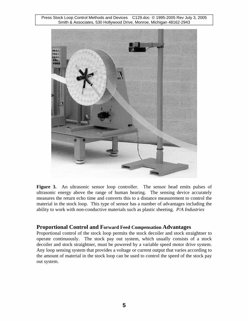
Figure 3. An ultrasonic sensor loop controller. The sensor head emits pulses of ultrasonic energy above the range of human hearing. The sensing device accurately measures the return echo time and converts this to a distance measurement to control the material in the stock loop. This type of sensor has a number of advantages including the ability to work with non-conductive materials such as plastic sheeting. P/A Industries Proportional Control and Forward Feed Compensation Advantages Proportional control of the stock loop permits the stock decoiler and stock straightner to operate continuously. The stock pay out system, which usually consists of a stock decoiler and stock straightner, must be powered by a variable speed motor drive system. Any loop sensing system that provides a voltage or current output that varies according to the amount of material in the stock loop can be used to control the speed of the stock pay out system.
5

Press Stock Loop Control Methods and Devices C129.doc © 1995-2005 Rev July 3, 2005 Smith & Associates, 530 Hollywood Drive, Monroe, Michigan 48162-2943
Figure 4. A progressive die operation using an ultrasonic loop control sensor. The best systems vary the decoiler and stock straightner speed to achieve proportional control. For long feed pitches, forward feed compensation may also be used to advance extra material into the loop before feed advancement. Smith & Associates The most common sensing system that provides this feature is the ultrasonic system described in reference one. The paper by Andy Cary, an engineer at Coil Technology, Inc. Of Wadsworth, Ohio describes the way an electrical feedback control system works to provide continuous operation of the pay out system. This paper is cited in reference one. One term for such a system is proportional control since the pay out system can operate continuously so long as the press is running. Material is fed into the loop in proportion to the rate that the press feeder depletes the loop. By anticipating when the press feeder is going to advance stock into the die, forward feed compensation can also be accomplished. Forward feed compensation advances material into the feed loop rapidly. This is useful for long feed progressions Other Loop Sensing Systems that can be used for Proportional Control Not all types of ultrasonic sensors provide a voltage or current output that is proportional to the distance from the stock loop. Some have set points, which provide simple on/off control. The best sensors provide an electrical output that varies according to the distance from the stock loop for proportional control. Some other types include:
1. Radio frequency sensors, one of which is illustrated in Figure 5. 2. Mechanical arms which have a rheostat or potentiometer to provide a variable
electrical output. 3. Arrays of multiple photoelectric sensors, which provide variable electrical output.
6

Press Stock Loop Control Methods and Devices C129.doc © 1995-2005 Rev July 3, 2005 Smith & Associates, 530 Hollywood Drive, Monroe, Michigan 48162-2943
Figure 5. A radio frequency (RF) loop control device. Note the “V” shaped antenna. The amount of RF energy absorbed by the stock increases when the material loop is higher. This sensing device provides an electrical output that can be used for proportional loop control. P&A Industries Stock Loop Pits A stock loop pit is sometimes required to provide enough material for long feed pitches. This should only be done if other measures such as applying forward feed advancement, which is timed to start feeding material into the loop before the feeder is actuated, will not provide enough slack in the loop. A stock-looping pit is illustrated in Figure 6. Pits should be avoided for several good reasons that include:
1. Pits are expensive to construct. 2. Future plant layout changes are apt to be difficult if a pit location is involved. 3. Pits require guardrails for safety of personnel. 4. Stock loop pits have a magical attraction for debris.
7

Press Stock Loop Control Methods and Devices C129.doc © 1995-2005 Rev July 3, 2005 Smith & Associates, 530 Hollywood Drive, Monroe, Michigan 48162-2943
Figure 6. A stock loop pit is sometimes required to provide enough material for long feed pitches. Such pits should be used only if necessary. Smith & Associates
Figure 7. An example of placing the press too far from the stock straightner. The usual reason is an erroneous belief that more stock can be accumulated if the distance between the pay out equipment and the press feeder is made longer. Smith & Associates Avoid Excessive Loop Lengths When conducting plant audits to determine more efficient ways to accomplish stamping operations, it has been the writer’s experience to observe many coil fed operations that have excessive distances between the decoiler and press feeder. The stated reason is usually an erroneous belief that more stock can be accumulated if the distance between the pay out equipment and the press feeder is made longer.
8

Press Stock Loop Control Methods and Devices C129.doc © 1995-2005 Rev July 3, 2005 Smith & Associates, 530 Hollywood Drive, Monroe, Michigan 48162-2943
This improper equipment placement is illustrated in Figure 7. In some cases, twenty or more feet (6 or more meters) of stock are on the floor. The main factors that determine the amount of material that can be stored in the stock loop are:
1. The height of the pay out equipment and press feeder above the floor. 2. The permissible bend radius of the stock forming the loop, which determines the
optimum distance between the press, and pay out device. Effect of Stock Loop Contacting the Floor Figure 6 illustrates a stock loop lying on the floor. There is an erroneous belief in some shops that moving the stock pay out devices as far as possible from the press increases the available amount of stock in the loop. This is incorrect, and has a number of undesirable consequences, which include:
1. Excessive floor space is occupied without providing any benefit. 2. The stock will become contaminated by any dirt on the floor. 3. Persons will almost certainly walk on the stock. 4. Industrial trucks may be driven over the stock. 5. Sometimes felt pads or skate roller conveyor is placed under the stock to keep it
off the floor. This adds to cost without addressing the layout problem. Joining Coils by Welding Welding equipment specifically designed for joining coil ends at the press is commercially available. This procedure is especially useful for jobs that are difficult to start. A means of cutting the coil ends to provide square edges to weld is required. The joining process must produce a weld that will not damage the die. Depending on the application, any parts containing the weld are discarded although they passed through the die without causing damage and appear to be correctly formed. Coil end welding has widespread application in the roll forming, tubing and pipe manufacturing operations. The majority of tube and pipe making operations from strip mills utilize welders to join the end of the coiled strip or skelp, an industry term for the some of the steel strip material that is formed into pipe. Tube, pipe roll formed product production is an excellent application. It is much weld coil ends together than to rethread a processing line. In the Tube and Roll Form Industries the higher speeds use more coils per shift making the coil welding process more easily justified through the reduction of coil related downtime. In the press industry, on the other hand, the reduction in scrap and tooling damage play a big factor in the justification of coil end welding.
9

Press Stock Loop Control Methods and Devices C129.doc © 1995-2005 Rev July 3, 2005 Smith & Associates, 530 Hollywood Drive, Monroe, Michigan 48162-2943
Joining coils together is becoming increasingly popular in the press industry. By eliminating rethreading, you will greatly reduce scrap, tooling damage and downtime. Many progressive die operations are difficult to start without the production of scrap and possible die damage. Welding coils together can reduce scrap and die damage. The material savings can be multiplied several times for non-ferrous materials. Formula for Determining the Loop Radius That Will Deform the Stock The following formula is based on elementary strength of materials. The greatest uncertainty in using this formula is the actual yield point of the material.
E⋅t R = −−−−− Equation 1
2⋅σy
Where: E = Young’s Modulus σy = Yield Strength
t = Material Thickness Applying the Minimum Bend Radius Formula to Stock Loops The stock in a simple material loop has four bend radii. These occur where the stock emerges from the pay out equipment such as the straightner. The second radius is where the stock bends from a vertical fall and assumes a horizontal plane toward the press. Next, the stock forms a radius as it bends upward toward the feeder and finally there is a radius where the stock enters the feeder. For the stock to remain flat, it is important not to exceed the minimum bend radius that will exceed the yield point of the stock. This may be calculated from Equation 1. Tabular data for a range of thicknesses and yield points is provided in Table 1. The normal minimum spacing of the pay out device assuming four radii is four times the minimum bend radius for the stock. To provide a safety factor, base the calculations on the thickest stock and lowest yield point that can be used. In addition, it is a good practice to assume that an error in equipment operation such as excessive stock pay out can occur. Please be aware that some of the values listed in Table 1 are not practical for many operations. This is especially true of low yield point stocks that are very thick.
10

Press Stock Loop Control Methods and Devices C129.doc © 1995-2005 Rev July 3, 2005 Smith & Associates, 530 Hollywood Drive, Monroe, Michigan 48162-2943
STEEL MINIMUM BEND RADIUS IN INCHES TO AVOID BENDING STRIP YIELD STRENGTH PSI THICKNESS 25,000 30,000 40,000 45,000 50,000 60,000 70,000 80,000
0.005 3.00 2.50 1.88 1.67 1.50 1.25 1.07 0.940.010 6.00 5.00 3.75 3.33 3.00 2.50 2.14 1.880.015 9.00 7.50 5.63 5.00 4.50 3.75 3.21 2.810.020 12.00 10.00 7.50 6.67 6.00 5.00 4.29 3.750.025 15.00 12.50 9.38 8.33 7.50 6.25 5.36 4.690.030 18.00 15.00 11.25 10.00 9.00 7.50 6.43 5.630.035 21.00 17.50 13.13 11.67 10.50 8.75 7.50 6.560.040 24.00 20.00 15.00 13.33 12.00 10.00 8.57 7.500.045 27.00 22.50 16.88 15.00 13.50 11.25 9.64 8.440.050 30.00 25.00 18.75 16.67 15.00 12.50 10.71 9.380.055 33.00 27.50 20.63 18.33 16.50 13.75 11.79 10.310.060 36.00 30.00 22.50 20.00 18.00 15.00 12.86 11.250.065 39.00 32.50 24.38 21.67 19.50 16.25 13.93 12.190.070 42.00 35.00 26.25 23.33 21.00 17.50 15.00 13.130.075 45.00 37.50 28.13 25.00 22.50 18.75 16.07 14.060.080 48.00 40.00 30.00 26.67 24.00 20.00 17.14 15.000.085 51.00 42.50 31.88 28.33 25.50 21.25 18.21 15.940.090 54.00 45.00 33.75 30.00 27.00 22.50 19.29 16.880.095 57.00 47.50 35.63 31.67 28.50 23.75 20.36 17.810.100 60.00 50.00 37.50 33.33 30.00 25.00 21.43 18.750.110 66.00 55.00 41.25 36.67 33.00 27.50 23.57 20.630.120 72.00 60.00 45.00 40.00 36.00 30.00 25.71 22.500.130 78.00 65.00 48.75 43.33 39.00 32.50 27.86 24.380.140 84.00 70.00 52.50 46.67 42.00 35.00 30.00 26.250.150 90.00 75.00 56.25 50.00 45.00 37.50 32.14 28.130.160 96.00 80.00 60.00 53.33 48.00 40.00 34.29 30.000.170 102.00 85.00 63.75 56.67 51.00 42.50 36.43 31.880.180 108.00 90.00 67.50 60.00 54.00 45.00 38.57 33.750.190 114.00 95.00 71.25 63.33 57.00 47.50 40.71 35.630.200 120.00 100.00 75.00 66.67 60.00 50.00 42.86 37.500.210 126.00 105.00 78.75 70.00 63.00 52.50 45.00 39.380.220 132.00 110.00 82.50 73.33 66.00 55.00 47.14 41.250.230 138.00 115.00 86.25 76.67 69.00 57.50 49.29 43.130.240 144.00 120.00 90.00 80.00 72.00 60.00 51.43 45.000.250 150.00 125.00 93.75 83.33 75.00 62.50 53.57 46.880.260 156.00 130.00 97.50 86.67 78.00 65.00 55.71 48.750.270 162.00 135.00 101.25 90.00 81.00 67.50 57.86 50.630.280 168.00 140.00 105.00 93.33 84.00 70.00 60.00 52.500.290 174.00 145.00 108.75 96.67 87.00 72.50 62.14 54.380.300 180.00 150.00 112.50 100.00 90.00 75.00 64.29 56.250.310 186.00 155.00 116.25 103.33 93.00 77.50 66.43 58.130.320 192.00 160.00 120.00 106.67 96.00 80.00 68.57 60.00
Table 1. Tabular data of minimum bend radii for a range of thicknesses and yield points.
11

Press Stock Loop Control Methods and Devices C129.doc © 1995-2005 Rev July 3, 2005 Smith & Associates, 530 Hollywood Drive, Monroe, Michigan 48162-2943
NOTES: _____________________________________________________ _____________________________________________________________ _____________________________________________________________ _____________________________________________________________ _____________________________________________________________ _____________________________________________________________ _____________________________________________________________ _____________________________________________________________ _____________________________________________________________ _____________________________________________________________ _____________________________________________________________ _____________________________________________________________ _____________________________________________________________ _____________________________________________________________ _____________________________________________________________ _____________________________________________________________ _____________________________________________________________ _____________________________________________________________ _____________________________________________________________
12