Presetting Valve Type RA-N with Flange Connection
8
Application The RA-N valve, code no. 013G1843, is specially designed for Russain convectors with 50 mm bot- tom connection. The valve body is designed for two-pipe pumped systems in commercial or domsetic heating sys- tems. RA-N has a built-in facility for setting max. flow through the convector. The setting options range from k v = 0.08 - 0.67 m 3 /h. Kvs = 0.88 m 3 /h The valve is deliveres assembled including moun- ted air ventilation screw and protective cap, red. All Danfoss thermostatic sensors in the RA series can be combined with the RA-N valve. In order to avoid deposition and corrosion, the composition of the hot water must be in accord- ance with the VDI 2035 guideline (Verein Deutscher Ingenieure). System Presetting Presetting area Reference mark The presetting values of the integrated valves can be adjusted easily and accurately without the use of tools (factory setting: ‘N’): ▪ Remove the protective cap or the thermo- static sensor ▪ Find the reference mark ▪ Turn the setting ring until the desired pre- setting number aligns with the reference mark. Data Sheet Presetting Valve Type RA-N with Flange Connection Danfoss Heating Solutions VDGWG102 © Danfoss 10/2012 1
Transcript of Presetting Valve Type RA-N with Flange Connection
Application
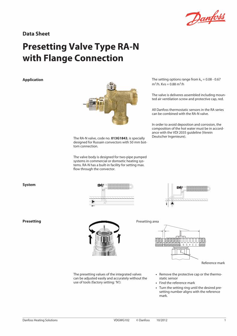
The RA-N valve, code no. 013G1843, is speciallydesigned for Russain convectors with 50 mm bot-tom connection.
The valve body is designed for two-pipe pumpedsystems in commercial or domsetic heating sys-tems. RA-N has a built-in facility for setting max.flow through the convector.
The setting options range from kv = 0.08 - 0.67m3/h. Kvs = 0.88 m3/h
The valve is deliveres assembled including moun-ted air ventilation screw and protective cap, red.
All Danfoss thermostatic sensors in the RA seriescan be combined with the RA-N valve.
In order to avoid deposition and corrosion, thecomposition of the hot water must be in accord-ance with the VDI 2035 guideline (VereinDeutscher Ingenieure).
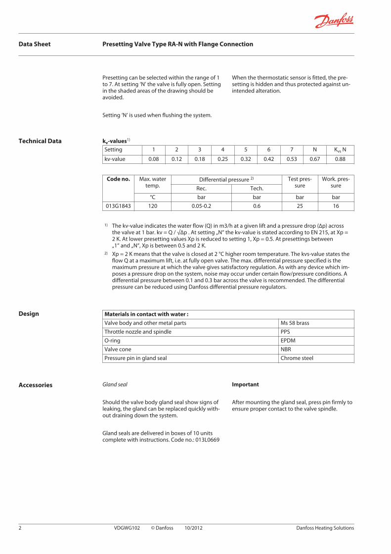
System
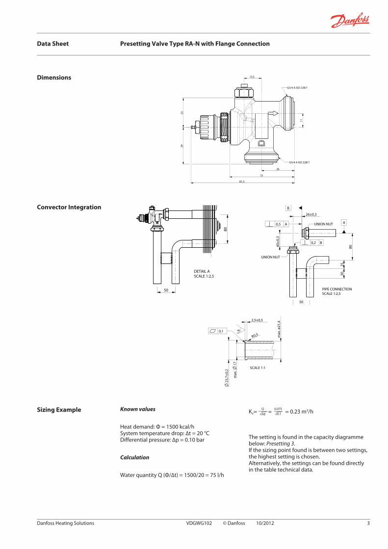
Presetting Presetting area
Reference mark
The presetting values of the integrated valvescan be adjusted easily and accurately without theuse of tools (factory setting: ‘N’):
▪ Remove the protective cap or the thermo-static sensor
▪ Find the reference mark▪ Turn the setting ring until the desired pre-
setting number aligns with the referencemark.
Data Sheet
Presetting Valve Type RA-N with Flange Connection
Danfoss Heating Solutions VDGWG102 © Danfoss 10/2012 1
Presetting can be selected within the range of 1to 7. At setting ‘N’ the valve is fully open. Settingin the shaded areas of the drawing should beavoided.
Setting ‘N’ is used when flushing the system.
When the thermostatic sensor is fitted, the pre-setting is hidden and thus protected against un-intended alteration.
Technical Data kv-values1)
Setting 1 2 3 4 5 6 7 N Kvs N
kv-value 0.08 0.12 0.18 0.25 0.32 0.42 0.53 0.67 0.88
Code no. Max. watertemp.
Differential pressure 2) Test pres-sure
Work. pres-sureRec. Tech.
°C bar bar bar bar013G1843 120 0.05-0.2 0.6 25 16
1) The kv-value indicates the water flow (Q) in m3/h at a given lift and a pressure drop (∆p) acrossthe valve at 1 bar. kv = Q / √∆p . At setting „N“ the kv-value is stated according to EN 215, at Xp =2 K. At lower presetting values Xp is reduced to setting 1, Xp = 0.5. At presettings between„1“ and „N“, Xp is between 0.5 and 2 K.
2) Xp = 2 K means that the valve is closed at 2 °C higher room temperature. The kvs-value states theflow Q at a maximum lift, i.e. at fully open valve. The max. differential pressure specified is themaximum pressure at which the valve gives satisfactory regulation. As with any device which im-poses a pressure drop on the system, noise may occur under certain flow/pressure conditions. Adifferential pressure between 0.1 and 0.3 bar across the valve is recommended. The differentialpressure can be reduced using Danfoss differential pressure regulators.
Design Materials in contact with water :
Valve body and other metal parts Ms 58 brassThrottle nozzle and spindle PPSO-ring EPDMValve cone NBRPressure pin in gland seal Chrome steel
Accessories Gland seal
Should the valve body gland seal show signs ofleaking, the gland can be replaced quickly with-out draining down the system.
Gland seals are delivered in boxes of 10 unitscomplete with instructions. Code no.: 013L0669
Important
After mounting the gland seal, press pin firmly toensure proper contact to the valve spindle.
Data Sheet Presetting Valve Type RA-N with Flange Connection
2 VDGWG102 © Danfoss 10/2012 Danfoss Heating Solutions
Dimensions
26
11
29
23
13,5
51
81,5
G3/4 A ISO 228/1
G3/4 A ISO 228/1
Convector Integration
80
50
DETAIL A
SCALE 1:2,5
A
B
50
26±0,3
0,5 A
40±0,3
25
30
80
UNION NUT
UNION NUT
0,2 B
PIPE CONNECTION
SCALE 1:2,5
ma
x. ø
21
,4
ma
x.
17
23
,7±
0,2
R0,5
2,5±0,5
1,6
SCALE 1:1
0,1
Sizing Example Known values
Heat demand: Φ = 1500 kcal/hSystem temperature drop: ∆t = 20 °CDifferential pressure: ∆p = 0.10 bar
Calculation
Water quantity Q (Φ/∆t) = 1500/20 = 75 l/h
Kv= = = 0.23 m3/hQ
√∆p
0.075
√0.1
The setting is found in the capacity diagrammebelow: Presetting 3.If the sizing point found is between two settings,the highest setting is chosen.Alternatively, the settings can be found directlyin the table technical data.
Data Sheet Presetting Valve Type RA-N with Flange Connection
Danfoss Heating Solutions VDGWG102 © Danfoss 10/2012 3

Capacity Diagramme (without radiator and tubing)
5 7 10 20 30 40 50 70 100 200 300 400 500 700 1000
1
2
3
4
5
6
8
kPa
20
30
40
5060
80
1001
0,8
0,6
0,5
0,4
0,3
0,2
0,1
0,08
0,06
0,05
0,04
0,03
0,02
0,01
10
pp
Q [l/h]
[ ][bar ]
0,1
0,2
0,3
0,4
0,5
0,6
0,8
1
2
3
4
5
6
8
10
p
1 2 3 4 5 6 7 N
107543210,70,50,40,30,20,1
200,2 0,3 0,4 0,5 0,7 1 2 3 4 5 7 10
kW
kW
t=15 Co
ot=20 C
]mwg[
2000
20 30
30 40
2t=10 C 0,40,1o
0,2 0,3 0,5 0,7 1 103 4 75 20 kW0,07
013G1843 RA-N
Instructions 1) 2)
3) 4)
Data Sheet Presetting Valve Type RA-N with Flange Connection
4 VDGWG102 © Danfoss 10/2012 Danfoss Heating Solutions

5) 6)Max. temperature
120ºCMax. temperature
120ºC60Nm
Data Sheet Presetting Valve Type RA-N with Flange Connection
Danfoss Heating Solutions VDGWG102 © Danfoss 10/2012 5

Data Sheet Presetting Valve Type RA-N with Flange Connection
6 VDGWG102 © Danfoss 10/2012 Danfoss Heating Solutions
Data Sheet Presetting Valve Type RA-N with Flange Connection
Danfoss Heating Solutions VDGWG102 © Danfoss 10/2012 7

Data Sheet Presetting Valve Type RA-N with Flange Connection
Danfoss A/SHeating SolutionsHaarupvaenget 118600 SilkeborgDenmarkPhone: +45 7488 8000Fax: +45 7488 8100Email: [email protected]
Danfoss can accept no responsibility for possible errors in catalogues, brochures and other printed material. Danfoss reserves the right to alter its products without notice. This also applies to productsalready on order provided that such alterations can be made without subsequential changes being necessary in specifications already agreed. All trademarks in this material are property of the respectivecompanies. Danfoss Heating Solutions and the Danfoss Heating Solutions logotype are trademarks of Danfoss A/S. All rights reserved.
8 VDGWG102 © Danfoss 10/2012 Danfoss Heating Solutions