Presented by Ken LaBel, HEART Short Course Albuquerque, NM, March 12, 2003 · Presented by Ken...
54
Presented by Ken LaBel, HEART Short Course Albuquerque, NM, March 12, 2003
-
Upload
phungkhanh -
Category
Documents
-
view
213 -
download
0
Transcript of Presented by Ken LaBel, HEART Short Course Albuquerque, NM, March 12, 2003 · Presented by Ken...

Presented by Ken LaBel, HEART Short Course Albuquerque, NM, March 12, 2003

Presented by Ken LaBel, HEART Short Course Albuquerque, NM, March 12, 2003 2
Abstract
• In this short course session, we will provide– An overview of the single particle-induced hazard for
space systems as they apply in the natural space environment.
• This shall focus on the implementation of a single event effects hardness assurance (SEEHA) program for systems including system engineering approach and mitigation of effects.
– The final portion of this session shall provide relevant real-life examples of in-flight performance of systems.

Presented by Ken LaBel, HEART Short Course Albuquerque, NM, March 12, 2003 3
Outline (1 of 2)
• Introduction– SEE: Impacting Space Operation– The SEE Hazard– SEE Effects
• Implementing SEEHA for a Space System– Hazard definition– SEE Requirements – a criticality-based method– Parts list review– Testing– Mitigative approaches– Monitoring performance during flight

Presented by Ken LaBel, HEART Short Course Albuquerque, NM, March 12, 2003 4
Outline (2 of 2)
• In-flight performance of systems– Systems with appropriate mitigation – success stories– Anomalies in flight
• Examples of impacts in-flight
• Summary• Acknowledgements

Presented by Ken LaBel, HEART Short Course Albuquerque, NM, March 12, 2003
Introduction

Presented by Ken LaBel, HEART Short Course Albuquerque, NM, March 12, 2003 6

Presented by Ken LaBel, HEART Short Course Albuquerque, NM, March 12, 2003 7
SEE: Definition

Presented by Ken LaBel, HEART Short Course Albuquerque, NM, March 12, 2003 8
SEE: The Effects

Presented by Ken LaBel, HEART Short Course Albuquerque, NM, March 12, 2003 9
Space Radiation Environment

Presented by Ken LaBel, HEART Short Course Albuquerque, NM, March 12, 2003 10
SEE and the Space Environment

Presented by Ken LaBel, HEART Short Course Albuquerque, NM, March 12, 2003 11
Solar Particle Events

Presented by Ken LaBel, HEART Short Course Albuquerque, NM, March 12, 2003 12
GCR Abundance: Integral LET Spectra

Presented by Ken LaBel, HEART Short Course Albuquerque, NM, March 12, 2003
Implementing SEE Hardness Assurance (SEEHA) for
a Space System

Presented by Ken LaBel, HEART Short Course Albuquerque, NM, March 12, 2003 14
Sensible SEEHA ProgrammaticsA Two-Pronged Approach
• Lead radiation PROJECT engineer– Integrate radiation like other engineering
disciplines• Parts, thermal,...
– Single point of contact for all radiation issues• Environment, parts evaluation, testing,…
• Follow a systematic approach to SEEHA– SEEHA active early in program reduces cost in
the long run• Issues discovered late in programs can be
expensive and stressful• Mission requirements and philosophies vary to
ensure mission performance– What works for a shuttle mission may not apply
to a deep-space mission

Presented by Ken LaBel, HEART Short Course Albuquerque, NM, March 12, 2003 15
Rational SEEHA for Space Systems
• Define the Environment– External to the spacecraft– Internal to the spacecraft
• Develop SEE Specification based on Criticality Factors
• Evaluate Design/Components– Existing data/Testing/Performance characteristics
• Work with spacecraft designers– Mitigative Approaches
• Iterate Process– Ex., Review parts list and usage on six month intervals based
on updated knowledgebase• Monitor Performance During Flight

Presented by Ken LaBel, HEART Short Course Albuquerque, NM, March 12, 2003 16
Define the Hazard for SEE:External Environment

Presented by Ken LaBel, HEART Short Course Albuquerque, NM, March 12, 2003 17
Define the Hazard for SEE:Internal Environment

Presented by Ken LaBel, HEART Short Course Albuquerque, NM, March 12, 2003 18
SEE Requirements based onCriticality Factors
• SEE is very application specific– Utilize a criticality analysis (SEECA) based on function
• Often allows use of non-SEE immune devices in a rational manner
• Note: SEE are probabilistic events (MTBF), not long-term degradation (MTTF)– Relatively equal probabilities for 1st day of mission or last
day of mission (maybe by definition!)– Remember to consider worst-case environments
• Requirements may alternately be defined by system-level parameters such as data coverage rather than by piecepart requirements

Presented by Ken LaBel, HEART Short Course Albuquerque, NM, March 12, 2003 19
SEE - System Requirements (1 of 2)
• Perform SEECA based on predicted environment and criticality of function performed*– Define 3 categories of criticality:
• Error-critical: SEEs are unacceptable• Error-vulnerable: A low risk of SEE is acceptable• Error-functional: SEEs are acceptable. Mitigation means may be
added to make these SEEs acceptable.– Examples:
• Motion controller with a fatal error would be error-critical• A processor with a predicted upset rate of 1 per 10 years for a 1
year mission may be deemed error-vulnerable by the project management
• A solid state recorder (SSR) that has many errors coupled with a robust error detection and correction (EDAC) scheme would be error-functional.
* For further information see: Single Event Effects Criticality Analysis (SEECA) at http://radhome.gsfc.nasa.gov/radhome/papers/seecai.htm

Presented by Ken LaBel, HEART Short Course Albuquerque, NM, March 12, 2003 20
SEE – Criticality Decision Tree
Single Event EffectSeverity Assessment
Include effects of any error mitigation
in design
Function is Error-critical
No SEEs permitted
Procure Componentsso that Predicted Error Rate for Function is ~0
Procure Componentsso that Predicted Error
Rate for Function Meets Requirement
Add additional Mitigation for SEE to Design
Function isError-functional
Large number of SEEs can be tolerated
Function isError-vulnerable
Very low number of SEEs can be tolerated
AdditionalError Mitigation
Useful/Cost-effective
AdditionalError Mitigation
Useful/Cost-effective
YES
NO
YES
NO
YESNO
YES
YES
NO
From SEECA document NASA-GSFC radhome web pagehttp://radhome.gsfc.nasa.gov

Presented by Ken LaBel, HEART Short Course Albuquerque, NM, March 12, 2003 21
SEE - System Requirements (2 of 2)
• No SEE may cause permanent damage to a system or subsystem
• Evaluation based on Linear Energy Transfer (LET) threshold (LETth) criteria. LETth is the maximum LET value at which no SEE is observed.
– LETth > 100 MeV*cm2/mg. No analysis required.
– LETth between 15+-100 MeV*cm2/mg. Analysis performed for heavy ion component.
– LETth < 15 MeV*cm2/mg. Analysis performed for heavy ion and proton components.
– Analysis (SEE rate prediction) must be performed not only for nominal conditions, but worst-case operate-through conditions.
+ These numbers are technology and mission specific. The numbers here are simply examples.
1.E-12
1.E-11
1.E-10
0 20 40 60 80 100 120Angle (Degrees)
Dev
ice
Cro
ss S
ectio
n (c
m2 )
DUT #5DUT #3
Proton-inducedangular effectsin SOI device with highaspect ratio
after Reed, 2002

Presented by Ken LaBel, HEART Short Course Albuquerque, NM, March 12, 2003 22
Sample Single Event Effects Specification (1 of 3)
1. Definitions and TermsSingle Event Effect (SEE) - any measurable effect to a circuit due to an ion strike. This includes (but is not limited to) SEUs, SHEs, SELs, SEBs, SEGRs, and Single Event Dielectric Rupture (SEDR).
Single Event Upset (SEU) - a change of state or transient induced by an energetic particle such as a cosmic ray or proton in a device. This may occur in digital, analog, and optical components or may have effects in surrounding interface circuitry (a subset known as Single Event Transients (SETs)). These are “soft” errors in that a reset or rewriting of the device causes normal device behavior thereafter.
Single Hard Error (SHE) - an SEU which causes a permanent change to the operation of a device. An example is a stuck bit in a memory device.
Single Event Latchup (SEL) - a condition which causes loss of device functionality due to a single event induced high current state. An SEL may or may not cause permanent device damage, but requires power strobing of the device to resume normal device operations.
Single Event Burnout (SEB) - a condition which can cause device destruction due to a high current state in a power transistor.
Single Event Gate Rupture (SEGR) - a single ion induced condition in power MOSFETs which may result in the formation of a conducting path in the gate oxide.
Multiple Bit Upset (MBU) - an event induced by a single energetic particle such as a cosmic ray or proton that causes multiple upsets or transients during its path through a device or system.
Linear Energy Transfer (LET) - a measure of the energy deposited per unit length as a energetic particle travels through a material. The common LET unit is MeV*cm2/mg of material (Si for MOS devices, etc.).
Onset Threshold LET (LETth0) - the minimum LET to cause an effect at a particle fluence of 1E7 ions/cm2(per JEDEC). Typically, a particle fluence of 1E5 ions/cm2 is used for SEB and SEGR testing.

Presented by Ken LaBel, HEART Short Course Albuquerque, NM, March 12, 2003 23
Single Event Effects Specification (2 of 3)
2. Component SEU Specification
2.1 No SEE may cause permanent damage to a system or subsystem.
2.2 Electronic components shall be designed to be immune to SEE induced performance anomalies, or outages which require ground intervention to correct. Electronic component reliability shall be met in the SEU environment.
2.3 If a device is not immune to SEUs, analysis for SEU rates and effects must take place based on LETth of the candidate devices as follows:
Device Threshold Environment to be Assessed
LETth < 15* MeV*cm2/mg Cosmic Ray, Trapped Protons, Solar Proton Events
LETth = 15*-100 MeV*cm2/mg Galactic Cosmic Ray Heavy Ions, Solar Heavy Ions
LETth > 100 MeV*cm2/mg No analysis required
2.4 The cosmic ray induced LET spectrum which shall be used for analysis is given in Figure TBD.
2.5 The trapped proton environment to be used for analysis is given in Figures TBD. Both nominal and peak particle flux rates must be analyzed.
2.6 The solar event environment to be used for analysis is given in Figure TBD.
2.7 For any device that is not immune to SEL or other potentially destructive conditions, protective circuitry must be added to eliminate the possibility of damage and verified by analysis or test.
*This number is somewhat arbitrary and is applicable to “standard” devices.Some newer devices may require this number to be higher.

Presented by Ken LaBel, HEART Short Course Albuquerque, NM, March 12, 2003 24
Single Event Effects Specification (3 of 3)
2. Component SEU Specification (Cont.)
2.8 For SEU, the criticality of a device in it's specific application must be defined into one of three categories: error-critical, error-functional, or error-vulnerable. Please refer to the /radhome/papers/seecai.htm Single Event Effect Criticality Analysis (SEECA) document for details. A SEECA analysis should be performed at the system level.
2.9 The improper operation caused by an SEU shall be reduced to acceptable levels. Systems engineering analysis of circuit design, operating modes, duty cycle, device criticality etc. shall be used to determine acceptable levels for that device. Means of gaining acceptable levels include part selection, error detection and correction schemes, redundancy and voting methods, error tolerant coding, or acceptance of errors in non-critical areas.
2.10 A design's resistance to SEE for the specified radiation environment must be demonstrated.
3. SEU Guidelines
Wherever practical, procure SEE immune devices. SEE immune is defined as a device having an LETth > 100 MeV*cm2/mg.
If device test data does not exist, ground testing is required. For commercial components, testing is recommended on the flight procurement lot.
Presented by Ken LaBel, HEART Short Course Albuquerque, NM, March 12, 2003 25
Evaluate Design/Component Usage
• Screen/review parts list– Use existing databases
• DTRA’s ERRIC, RADATA, REDEX, Radhome, ESA Database,IEEE TNS, IEEE Data Workshop Records, Proceedings of RADECS, etc.
• Evaluate completeness and relevance of test data– Look for processes or products with known radiation tolerance
(beware of SEE and displacement damage!)• BAE Systems, Honeywell Solid State Electronics, UTMC, Intersil, etc.
• Radiation test unknowns or non-RH guaranteed devices– Lot qualification recommended– Qualification by similarity is a risk trade
• Provide performance characteristics– Usually requires application specific information: understand the
designer’s sensitive parameters• SEE rates and impacts to system
Stacked devices and hybridscan present a unique challenge
for review and test

Presented by Ken LaBel, HEART Short Course Albuquerque, NM, March 12, 2003 26
Scrubbing of parts lists

Presented by Ken LaBel, HEART Short Course Albuquerque, NM, March 12, 2003 27
After K. LaBel, IEEE TNS vol 45-6, 1998
Data Search and Definitionof Data Usability Flow
YES NO YES YES YES

Presented by Ken LaBel, HEART Short Course Albuquerque, NM, March 12, 2003 28
Data Applicability – Example 1
Presented by Ken LaBel, HEART Short Course Albuquerque, NM, March 12, 2003 29
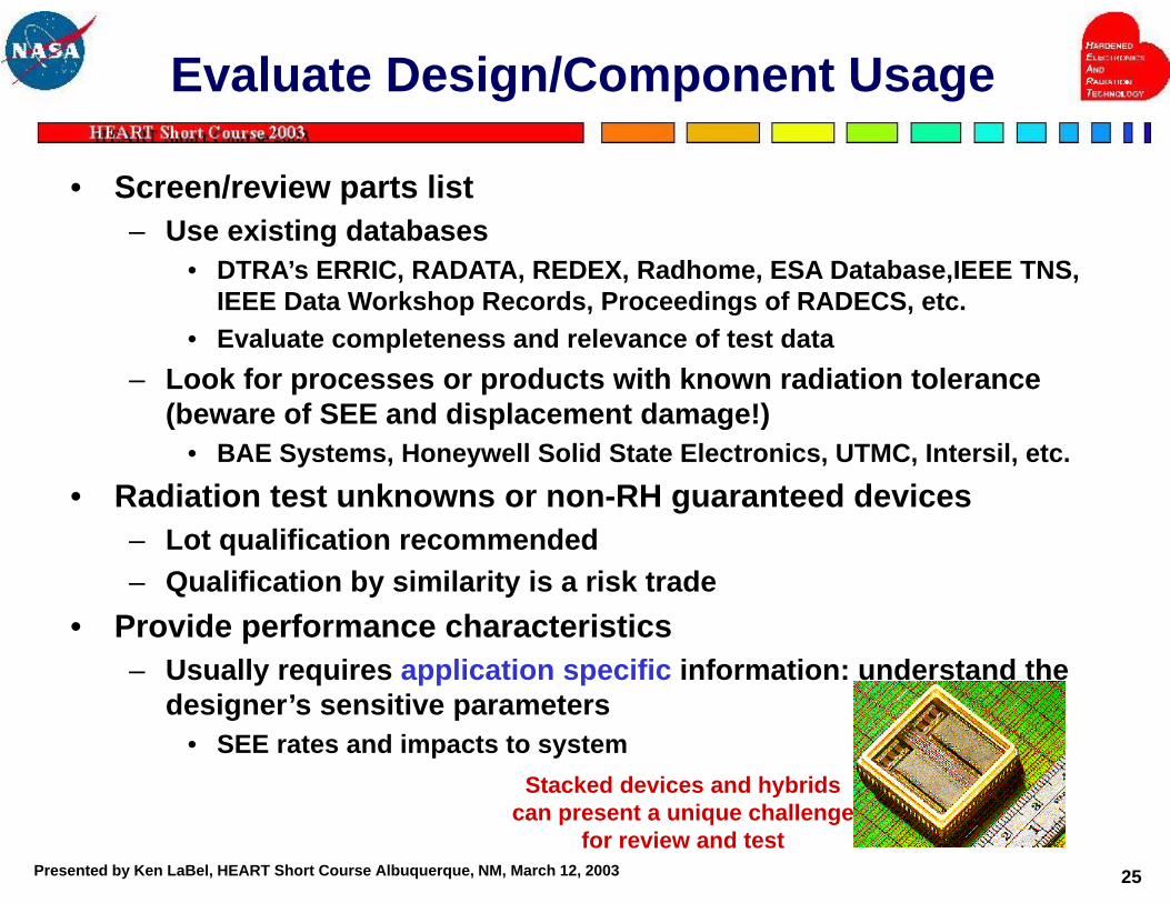
Data Applicability - Example 2

Presented by Ken LaBel, HEART Short Course Albuquerque, NM, March 12, 2003 30
SEE Radiation Test Requirements

Presented by Ken LaBel, HEART Short Course Albuquerque, NM, March 12, 2003 31
Radiation Test Issues - Fidelity
GroundTest
FlightTest
Mixed particlespecies
Combinedenvironmen
teffects
Omnidirectionalenvironment
Broad energyspectrum Actual
particle rates
Single particlesources
Individualenvironment
effects Unidirectionalenvironment
Monoenergeticspectrum
Acceleratedparticle rates
Actual conditions Simulated conditionsHow accurate is the
ground test in predicting Space Performance?Example, how does dose degradation and aging effects affect SEE performance?
After Stassinopoulos

Presented by Ken LaBel, HEART Short Course Albuquerque, NM, March 12, 2003 32
Work with Space System Designers
• Determine and validate “acceptable” performance characteristics– E.g., SEU rates using accepted methods
• By test• By simulation or circuit analysis• By determining SEU rate (CREME96, SPACERAD, etc) and
managing risk– I.e., is the probability/risk of observing an SEU sufficiently low?
» e.g., a SEU rate of 1 per 10 years for a 1 month mission
• Recommend mitigation schemes– Recommend alternate parts that meet performance
requirements– Recommend error detection and correction (EDAC) schemes,
redundancy, voting,...– The following few charts are overviews of device and circuit
hardening concepts

Presented by Ken LaBel, HEART Short Course Albuquerque, NM, March 12, 2003 33
IC Hardening (1 of 2)

Presented by Ken LaBel, HEART Short Course Albuquerque, NM, March 12, 2003 34
IC Hardening (2 of 2)
• Advantages– Simplifies system design to meet radiation
requirements• Challenges
– Performance, Cost, Schedule• Examples
– Hardened process– Compiled or hardened library design (hardness
by design (HBD) techniques)

Presented by Ken LaBel, HEART Short Course Albuquerque, NM, March 12, 2003 35
Circuit Hardening (1 of 2)
• Implies adding an external feature to an IC to reduce radiation sensitivity– Shielding– RC filter– Voting logic– Error detection and correction (EDAC) codes– Watchdog timers, etc.
• Maybe be implemented or controlled by either hardware, software, or firmware
LEDPhotodiode or
phototransistorAmplifier
Stage
Input LightExternalBandpassFilter
8 Mhz input(125 nsecpulsewidth) 55 nsec
transientfor <75 nsectransients
filteredoutput

Presented by Ken LaBel, HEART Short Course Albuquerque, NM, March 12, 2003 36
Circuit Hardening (2 of 2)
• Advantages– Allows use of higher (non-radiation) performance
ICs• Faster processors• Denser memories, etc…
• Challenges– Adds complexity (cost and schedule?) to design– Often difficult to retrofit if problem is discovered
late• Modification to flight hardware

Presented by Ken LaBel, HEART Short Course Albuquerque, NM, March 12, 2003 37
Circuit Mitigation of SEUs

Presented by Ken LaBel, HEART Short Course Albuquerque, NM, March 12, 2003 38
Data SEUs - Sample EDAC Methods
EDAC Method EDAC CapabilityParity Single bit error detect
Cyclic RedundancyCheck (CRC)
Detects if any errors have occurred in agiven structure
Hamming Code Single bit correct, double bit detect
Reed-Solomon Code Corrects multiple and consecutive bytesin error
Convolutional Code Corrects isolated burst noise in acommunication stream
Overlying Protocol Specific to each system. Example:retransmission protocol

Presented by Ken LaBel, HEART Short Course Albuquerque, NM, March 12, 2003 39
Control SEUs - Sample EDAC Schemes
• Software-based health and safety (H&S) tasks• Watchdog timers• Redundancy• Lockstep• Voting• “Good engineering practices”
– Ex., send two commands with different values to initiate a sequence
• Improved Designs (i.e., noise margins, method of sampling, etc.)

Presented by Ken LaBel, HEART Short Course Albuquerque, NM, March 12, 2003 40
Transients from SEUs (SETs)

Presented by Ken LaBel, HEART Short Course Albuquerque, NM, March 12, 2003 41
Destructive SEE - Mitigation
after O’Bryan, 2002

Presented by Ken LaBel, HEART Short Course Albuquerque, NM, March 12, 2003 42
Latent Damage

Presented by Ken LaBel, HEART Short Course Albuquerque, NM, March 12, 2003 43
Iterate Process as Necessary• Design or requirement changes often occur during
design and build of space systems– New parts (or new usage of existing parts) need review or
test– Internal hazard may require re-evaluation (I.e., new 3-D ray
trace)• Re-review of parts list and applications
– If the design/development is more than a few months, new knowledge (research) is sometimes obtained making “old parts, new issues”
• Presentations at conferences highlight new sensitivities in devices/technologies
– New SEE modes are sometimes uncovered– Ex., optocoupler SETs

Presented by Ken LaBel, HEART Short Course Albuquerque, NM, March 12, 2003 44
Monitor System Performance In-Flight

Presented by Ken LaBel, HEART Short Course Albuquerque, NM, March 12, 2003
In-Flight Performance ofActual NASA Systems

Presented by Ken LaBel, HEART Short Course Albuquerque, NM, March 12, 2003 46
Success Stories
• A brief overview will be provided of several NASA missions which performed as expected in space due to SEEHA– Each can be traced back to particular lessons they
provided• Three examples
– Solid State Recorders (SSRs)• SeaStar• Hubble Space Telescope (HST)
– COTS Processors• HST Co-processor

Presented by Ken LaBel, HEART Short Course Albuquerque, NM, March 12, 2003 47
SeaStar SSR

Presented by Ken LaBel, HEART Short Course Albuquerque, NM, March 12, 2003 48
Hubble Space Telescope (HST) SSR

Presented by Ken LaBel, HEART Short Course Albuquerque, NM, March 12, 2003 49
HST Co-Processor:Acceptable Mission Risk

Presented by Ken LaBel, HEART Short Course Albuquerque, NM, March 12, 2003 50
Anomalies In-Flight

Presented by Ken LaBel, HEART Short Course Albuquerque, NM, March 12, 2003 51
HST Optocouplers
• In February of 1997, several anomalies occurred in a HST instrument while transiting through the SAA– High-speed optocoupler identified as
the potential source• This was verified by ground testing in
March 1997 for SETs– Device was not reviewed for radiation
issues other than total dose• Common thought before this timeframe
on slower optocouplers• Science instrument operations
modified such that no operations were active during SAA transits– Loss of some (luckily non-critical)
science data• Mission still successful

Presented by Ken LaBel, HEART Short Course Albuquerque, NM, March 12, 2003 52
Microwave Anisotropy Probe (MAP):SETs in a Linear Device
• MAP was launched in June 2001 to a L2 orbit– Anomaly occurred in Nov 2001 causing the
command and data handling processor to reset
• System worked as designed for recovery of anomalies (safehold, await command to restart)
• Event occurred during a solar particle event– Heavy ion (not proton) contribution was likely
the cause• Linear comparator used with a small
differential input– Much more sensitive than with larger
differential input• Design requirements changed during mission
design and what was originally a tolerant application (large differential) became “soft” to SETs
Robust system design recovered from unexpected event
Presented by Ken LaBel, HEART Short Course Albuquerque, NM, March 12, 2003 53
Summary
• In this brief time, we have presented an system-level approach to dealing with space system design and SEE
• It is important to start ANY radiation assurance planning early in mission design and to continue throughout
• It is the challenge of every design engineer to make sure his or her design is robust with the aid of the radiation specialist

Presented by Ken LaBel, HEART Short Course Albuquerque, NM, March 12, 2003 54
Acknowledgements
• The entire Radiation Effects and Analysis Group at GSFC NASA HQ Code AE for supporting the NASA Electronic Parts and Packaging (NEPP) Program including the Program Manager, Chuck Barnes of JPL
• Lew Cohn at Defense Threat Reduction Agency (DTRA)
• The designers and systems engineers I’ve had the privilege to work with
• Martha O’Bryan and Donna Cochran for graphics support