Presentation 1
22
16 Bit SRAM Implementation and Analysis Project by Aamodh K , Arjun S Kumar and Vikas Bhardwaj (M.Tech VLSI Design)
-
Upload
aamodh-kuthethur -
Category
Documents
-
view
214 -
download
2
description
SRAM Design Project
Transcript of Presentation 1

16 Bit SRAM Implementation and Analysis
Project
by
Aamodh K , Arjun S Kumar and Vikas Bhardwaj
(M.Tech VLSI Design)
What Is Our Project All About
Figure: Image Source : Intel

Why SRAM Based Project
I Reason 1 : Innovation in SRAM is still in vogue in industryI December 2013: Taiwan Semiconductor Manufacturing
Company (TSMC) unveil SRAM cell of size 0.07 um2 in 16nmtechnology.[1]
I February 2015: Intel respond by unveiling worlds’ smallest (cell size of 0.05 um2) SRAM till date in 14nm technology,capable of storing 14.5Mb per mm2 [2]
I Intel and TSMC plan to unveil FinFET SRAM at 10nmtechnology in 2016. [3]

Why SRAM Based Project
I Reason 2 : It is interesting to learn about a part of a productwe use very often.
I Applications of SRAM:I Cache memory on processorsI RegistersI LCD TVs [4]I Printer [5]

Project Agenda
I Design of 16 Bit 6T SRAM Cell
I Design of peripheral circuitry − Decoder, Sense Amplifier,Pre-charge circuit, Write enable circuitry
I Simulation and Testing of 16 bit SRAM at circuit and layoutlevel
I Characterization of 6T SRAM Cell based onI Static Noise MarginI Read and Write DelayI Static Power Dissipation

Block diagram of 16 bit SRAM

Schematic of 1 bit 6T SRAM
I Design details to take care of:I Cell Ratio (CR)I Pull-up Ratio (PR)

Why worry about cell ratio and pullup ratio
I To prevent destructive read

Need Of Peripheral Circuitry
I Sense AmplifierI To nullify the negative effect of parasitic bit and word line
capacitances.I To increase the logic detection speed during read operation.
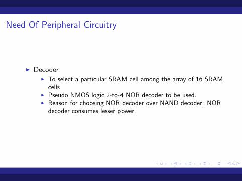
Need Of Peripheral Circuitry
I DecoderI To select a particular SRAM cell among the array of 16 SRAM
cellsI Pseudo NMOS logic 2-to-4 NOR decoder to be used.I Reason for choosing NOR decoder over NAND decoder: NOR
decoder consumes lesser power.

Need Of Peripheral Circuitry
I Pre charge circuit:I To prevent unwanted toggling of cell state by maintaining
preset voltage on bit lines.
Need Of Peripheral Circuitry
I Data enable circuitI To control the data write operation.

Perfomance Parameters
I Static Noise Margin (SNM):I SNM of SRAM is defined as minimum amount of noise voltage
on the storing nodes of SRAM required to flip the state of cell.I How do we plan to measure SNM? Using NGSpice and Perl
scripting.
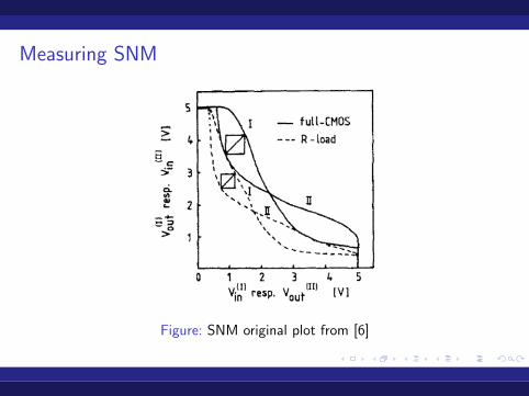
Measuring SNM
Figure: SNM original plot from [6]

Perfomance Parameters
I Write delayI Delay in writing data into the cell
I Read delayI Delay in reading data out of the cell
I Static Power DissipationI Power dissipation in Hold state of the cell

Resources To Be Used
I For circuit simulation: NgSpice,IRSim
I For layout design: Magic
I For Layout Versus Schematic: Netgen
I For calculation of Read and Write delay: Perl/Python

Timeline

Circuit diagram

SRAM cell design
I SRAM cell design :I For Vdd=3.3V and mobility and threshold voltage values in
level 49 ngspice modelI Cell Ratio>4.051 (selected value: 4.2)I Pullup Ratio<0.481 (selected value: 0.4)

Plots Obtained

Layout
References
1. Intel vs. TSMC: An Updatehttp ://electroiq.com/blog/2014/01/intel−vs−tsmc−an−update
2. Intel Carves Tiny SRAMs at 14nmhttp : //www .eetimes.com/document.asp?docid = 1325734
3. TSMC Outlines 16nm, 10nm Planshttp : //www .eetimes.com/document.asp?docid = 1326286
4. http : //www .st.com/st − web −ui/static/active/en/resource/technical/document/applicationnote/CD00201397.pdf
5. http : //www .memoryx .com/troyajn.html
6. E. Seevinck, F. List, and J. Lohstroh, Static-noise marginanalysis of mos sram cells Solid-State Circuits, IEEE Journalof,, vol. 22, no. 5, pp. 748 754, Oct. 1987.