
Prepr int - Diva1080664/FULLTEXT01.pdf · Prepr int This is the submitted version of a paper...
16
http://www.diva-portal.org Preprint This is the submitted version of a paper published in . Citation for the original published paper (version of record): Andersson, M., Sosa, M., Olofsson, U. [Year unknown!] Efficiency and temperature of spray lubricated superfinished spur gears. Access to the published version may require subscription. N.B. When citing this work, cite the original published paper. Permanent link to this version: http://urn.kb.se/resolve?urn=urn:nbn:se:kth:diva-202985
Transcript of Prepr int - Diva1080664/FULLTEXT01.pdf · Prepr int This is the submitted version of a paper...

http://www.diva-portal.org
Preprint
This is the submitted version of a paper published in .
Citation for the original published paper (version of record):
Andersson, M., Sosa, M., Olofsson, U. [Year unknown!]Efficiency and temperature of spray lubricated superfinished spur gears.
Access to the published version may require subscription.
N.B. When citing this work, cite the original published paper.
Permanent link to this version:http://urn.kb.se/resolve?urn=urn:nbn:se:kth:diva-202985

Efficiency and temperature of spray lubricatedsuperfinished spur gears
M. Anderssona,∗, M. Sosaa, U. Olofssona
aKTH Royal Institute of Technology, Dept. Machine Design. Brinellvagen 83, 100 44Stockholm Sweden
Abstract
Gearboxes are one of the most power dense systems used today, and in certaininstances their limiting factor is the ability to evacuate heat from the gearcontact. This work analyses the efficiency (i.e. heat generation) and toothtemperature in the three lubricating conditions dip, into mesh spray and out ofmesh spray for superfinished gears which are then compared to ground gears.A back-to-back gear test rig is employed to test maximum contact pressuresat the pitch of 0.59 to 0.96 GPa and pitch velocities from 0.5 to 20 m/s at acontrolled lubricant temperature of 90 ◦C. The results show superfinished gearshave higher mesh efficiency and lower gear tooth and bulk temperatures, hencelower heat flux compared to ground gears in all lubricating conditions.
Keywords: Spray lubrication, efficiency, gear temperature, superfinish
1. Introduction
To keep gearboxes simultaneously efficient and at low temperatures can bechallenging.
Gear related power losses in gearboxes can be separated into load-independentand load-dependent losses, which origins from the gear mesh, the lubricantand windage of the gearbox medium. When gears are dip lubricated, load-independent losses can be reduced by lowering the immersion depth [1]. Thiseffect is also seen when spray lubrication is used and there is no oil sump [2].Lubricants with lower viscosities also reduced load-independent losses due toeasier shear of the lubricant [3]. On the other hand, higher immersion depths ofgears help to cool the gears and higher viscosity grades of lubricants separatesgear flanks easier.
Load-dependent power losses related to the gear mesh have been studiedpreviously. Xiao et al. suggested lower gear mesh power losses as the surfacegets smoother [4]. Petry-Johnson et al. studied the difference between groundand chemically polished gears in dip lubrication and found a higher efficiencyfor superfinished gears [5]. Previous studies by the authors investigated theeffect of two different running-in procedures on ground and superfinished gears
∗Corresponding authorEmail addresses: [email protected] (M. Andersson), [email protected] (M. Sosa), [email protected]
(U. Olofsson)
and found the superfinished gears overall to be more efficient [6]. When testingspray lubrication, Britton et al. found a higher efficiency for superfinished gearscompared to ground gears [7].
In ideal conditions the lubricant can cool and separate gear flanks in allrunning conditions. Hohn and Michaelis investigated gear damages and foundlower risk of pitting and scuffing for lower lubricant temperatures [8]. Castroet al. investigated gear scuffing and suggested that there is a critical lubricantfilm thickness below which scuffing occurs [9]. Townsend and Shimski studiedthe influence of lubricant viscosity on the fatigue life of gears. They found apositive correlation of the fatigue lives of the tested gears and for calculatedthicker lubricating films [10]. Krantz et al. compared fatigue life of ground (Ra
0.38 µm) and superfinished gears (Ra 0.07 µm) and found strong evidence forlonger gear life for superfinished gears [11].
Previous work by the authors investigated spray lubricated ground gearsregarding efficiency, gear temperature and surface roughness compared to diplubricated ground gears. The results showed a higher total efficiency as well ashigher gear temperatures for spray lubricated gears [12].
Previous work have shown superfinished gears to be more efficient and theimportance of keeping lubricant temperatures low for longer gear lives [6, 7].The temperature of gears need to be further investigated for a possible reduc-tion of lubricant necessary for cooling. This work investigates the efficiency andtemperature of spray lubricated superfinished gears compared to spray lubri-cated ground gears. The following questions are investigated; Is there and towhat degree, a temperature difference between spray lubricated superfinishedgears compared to ground gears, and to what extent are spray lubricated groundand superfinished gears cooled.
2. Method
2.1. Equipment
Tests were made in an FZG gear test rig with an efficiency setup, Figure1. In each test, two unused pairs of gears with the same geometry and surfacefinish were mounted in the test gearbox (1) and the slave gearbox (3). To loadthe gears, dead weights were put on the load clutch (2). In this rig configurationpower losses which occur equal the torque which the motor provides (5). Theinput torque is measured by the torque and speed sensor (4).
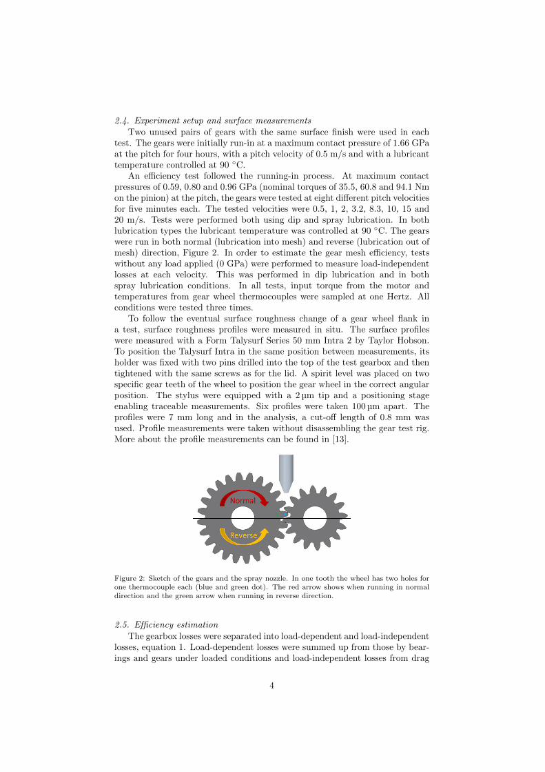
The gears used in all tests were FZG C-Pt gears (16MnCr5) with the in-clusion of tip relief, Table 1. To enable temperature measurements in the gearwheel in the test gearbox during testing, two holes were drilled axially 44 and55 mm from the gear wheel centre where two thermocouples were attached,represented by a green and blue dot respectively in Figure 2 . The shaft on thewheel side of the test gearbox had an extended shaft with a hole drilled wheretwo thermocouples were pulled through to a slip ring.
2.2. Lubrication
A spray lubrication unit from Strama MPS was used to lubricate the gearsduring spray lubrication testing. The lubricant was injected with a velocity of0.4 m/s corresponding to 0.025 l/s. A polyalphaolefin lubricant with nominalviscosities of 64.1 cSt at 40 ◦C and 11.8 cSt at 100 ◦C and a density of 837
2

kg/m3 was used in all tests. The nozzle was positioned above the gear mesh(directly above the pitch point), Figure 2. When dip lubrication was used theoil level reached the centre of the gears.
Figure 1: Top view of the FZG gear test rig, showing the test gearbox (1), load clutch (2),the slave gearbox (3), the torque and speed sensor (4) and the motor (5).
Table 1: FZG C-Pt geometrical parameters.
Parameter Standard Modified UnitCentre distance a 91.5 mmFace width b 14 mm
Pitch diameterdw1 73.2 mmdw2 109.8 mm
Tip diameterda1 82.46 mmda2 118.36 mm
Module mn 4.5 mm
Number of teethz1 16z2 24
Addendum modification factorx1 0.18x2 0.17
Pressure angle α 20 ◦
Working pressure angle αw 22.44 ◦
Helix angle β 0 ◦
Lead crowningCb1 0 µmCb2 0 µm
Tip reliefCa1 0 20 µmCa2 0 20 µm
Starting diameter for tip reliefdg1 0 80.3 mmdg2 0 115.9 mm
2.3. Manufacturing method
The gear specimens in this work were first ground, and later superfinished.Superfinishing of gears in this work refers to a chemical mechanical process inwhich the gears are subject to in order to decrease their surface roughness. Thegears superfinished came from the same batch as the ground gears. The Ra
decreased from 0.3 µm to 0.1 µm. The superfinish process did not change thegear’s macro-geometrical and micro-geometrical dimensions.
3
2.4. Experiment setup and surface measurements
Two unused pairs of gears with the same surface finish were used in eachtest. The gears were initially run-in at a maximum contact pressure of 1.66 GPaat the pitch for four hours, with a pitch velocity of 0.5 m/s and with a lubricanttemperature controlled at 90 ◦C.
An efficiency test followed the running-in process. At maximum contactpressures of 0.59, 0.80 and 0.96 GPa (nominal torques of 35.5, 60.8 and 94.1 Nmon the pinion) at the pitch, the gears were tested at eight different pitch velocitiesfor five minutes each. The tested velocities were 0.5, 1, 2, 3.2, 8.3, 10, 15 and20 m/s. Tests were performed both using dip and spray lubrication. In bothlubrication types the lubricant temperature was controlled at 90 ◦C. The gearswere run in both normal (lubrication into mesh) and reverse (lubrication out ofmesh) direction, Figure 2. In order to estimate the gear mesh efficiency, testswithout any load applied (0 GPa) were performed to measure load-independentlosses at each velocity. This was performed in dip lubrication and in bothspray lubrication conditions. In all tests, input torque from the motor andtemperatures from gear wheel thermocouples were sampled at one Hertz. Allconditions were tested three times.
To follow the eventual surface roughness change of a gear wheel flank ina test, surface roughness profiles were measured in situ. The surface profileswere measured with a Form Talysurf Series 50 mm Intra 2 by Taylor Hobson.To position the Talysurf Intra in the same position between measurements, itsholder was fixed with two pins drilled into the top of the test gearbox and thentightened with the same screws as for the lid. A spirit level was placed on twospecific gear teeth of the wheel to position the gear wheel in the correct angularposition. The stylus were equipped with a 2 µm tip and a positioning stageenabling traceable measurements. Six profiles were taken 100 µm apart. Theprofiles were 7 mm long and in the analysis, a cut-off length of 0.8 mm wasused. Profile measurements were taken without disassembling the gear test rig.More about the profile measurements can be found in [13].
Figure 2: Sketch of the gears and the spray nozzle. In one tooth the wheel has two holes forone thermocouple each (blue and green dot). The red arrow shows when running in normaldirection and the green arrow when running in reverse direction.
2.5. Efficiency estimation
The gearbox losses were separated into load-dependent and load-independentlosses, equation 1. Load-dependent losses were summed up from those by bear-ings and gears under loaded conditions and load-independent losses from drag
4
and churning of the lubricant caused by bearings, gears and seals. The mea-sured load-independent losses were subtracted from the total losses to end upwith the load-dependent losses.
Ttotal = Tload−dependent + Tload−independent (1)
To calculate the gearbox efficiency, equation 2 was used. This was madeby dividing the measured torque loss by the nominal torque transferred by thepinion (T1) and gear ratio (u). The ratio was then multiplied by 0.5 for theefficiency of one gearbox.
ηtotal = 1 − 0.5TtotaluT1
(2)
To estimate the gear mesh efficiency, a bearing model by SKF was first tested,but bearing frictional losses, for the gear contact pressures of 0.59 and 0.80 GPa,were overestimated at the higher speeds which yielded a mesh efficiency above100 %. Instead, a bearing model developed at the Department of MachineDesign KTH was used, equation 3. It was developed using a modified versionof the gear test rig shown in Figure 1. The values for constants A, B and Care presented in Appendix 1. More information about the bearing model canbe found in [14].
TSTA,1,2 = An+B
n+ C (3)
It is important to note that equation 3 is a function only of rotational speed(n); hence, for each oil, load, temperature, type of bearing and lubricationmethod a bearing test is needed and the data in this work is only valid for theconditions presented previously.
The load-dependent bearing losses were finally estimated with equation 4,where ω2 is the ingoing angular speed of the motor. In order to calculatethe frictional moment in the gear mesh, the load-dependent bearing losses weresubtracted from the load-dependent losses, equation 5. The gear mesh efficiencycould then be calculated using equation 6, where u is the gear ratio, T1 thenominal torque and 0.5 for the mesh efficiency in one gearbox.
Tbearing =4TSTA,1ω21.5 + 4TSTA,2ω2
ω2(4)
Tmesh = Tload−dependent − Tbearing (5)
ηmesh = 1 − 0.5Tmesh
uT1(6)
The difference between measured tooth temperature (ϑTooth) and measuredbulk temperature (ϑBulk) in the gear wheel (∆Wheel), is calculated with equa-tion 7.
∆Wheel = ϑTooth − ϑBulk (7)
5

3. Lubricant heat absorption estimation
To estimate the amount of heat absorbed by the lubricant in spray lubrica-tion, a second test setup different from the efficiency tests was performed. Toestimate the lubricant’s heat absorption, the injection lubricant temperaturefrom the nozzle was compared to the lubricant temperature at the outlet, mea-sured with a thermocouple. This was performed for contact pressures of 0 GPaand 0.96 GPa. Pitch velocities of 0.5, 2, 8.3 and 20 m/s were run for two minuteseach. After two minutes the gear wheel temperature had reached its mediantemperature. To reduce influence on the lubricant outlet temperature from thecasing, the inside of the test gearbox was insulated internally with PTFE. PTFEplates with a thickness of five mm covered the bottom and the walls and a onemm thick plate was put under the gearbox lid. This test setup was run in bothnormal and reverse direction for ground and superfinished gears.
Lubricant outlet temperatures (ϑ0) when run at 0 GPa were subtracted fromoutlet temperatures (ϑ0.96) when 0.96 GPa was run to achieve the temperaturedifference between nozzle and outlet (∆ϑLubricant) , equation 8.
∆ϑLubricant = ϑ0.96 − ϑ0 (8)
The amount of heat absorbed by the lubricant was calculated with equation9. The lubricant had a density (ρ) of 837 kg/m3, a specific heat capacity (C )of 2180 J/kgK and the amount of lubricant injected (V ) was 0.025 l/s. Theinjected lubricant temperature was 90 ◦C.
W = CρV∆ϑLubricant (9)
By using equation 9, one degree Celsius difference will equal a change of 43W in the oil energy balance.
6

4. Results
4.1. Gear efficiency and temperature
All three tests from the gear efficiency testing and temperature measure-ments are presented as the median, the minimum and the maximum value ofeach test. The results are presented as subplots (1 × 3), the tested maximumcontact pressures increase from left to right, 0.59, 0.80 and 0.96 GPa respec-tively.
In Figure 3, the total gearbox efficiency of dip and spray lubricated groundand superfinished gears is compared. From a pitch velocity of 8.3 m/s thedifference in efficiency between dip and spray lubrication is significant. Thebiggest difference is seen at 20 m/s at 0.59 GPa where dip lubricated gearsyield an efficiency of 94.5 % compared to 97.5 % for the least efficient groundgear. At 0.96 GPa the difference has decreased and is around 1 % at 20 m/sbetween the two lubrication methods.
Consequently, the superfinished gears are more efficient than the groundgears. A higher efficiency between 0.1 to 0.2 % can be seen for superfinishedgears.
0 5 10 15 2094
95
96
97
98
99
100
Gea
rbox
effi
cien
cy,η
tota
l [%]
0 5 10 15 20
Pitch velocity [m/s]
94
95
96
97
98
99
100
0 5 10 15 2094
95
96
97
98
99
100
ReverseNormalDip
SuperfinishedGround
Figure 3: Gearbox total efficiency comparing ground and superfinished gears for dip and spraylubrication, run in normal and reverse direction, at contact pressures of 0.59, 0.80 and 0.96GPa, presented from left to right. Ground gears are represented as solid lines and superfinishedas dashed lines.
Gear mesh efficiency is presented in Figure 4. At 20 m/s, spray lubricatedground gears at 0.59 and 0.80 GPa have a median mesh efficiencies of 99.8 %compared to 99.9 % for superfinished gears. At 0.96 GPa the ground gears havea median mesh efficiency of 99.7 % while the superfinished gears still yield amedian efficiency of 99.9 %. For all tested contact pressures, at 20 m/s thereis a trend that dip lubricated gears have a slightly lower mesh efficiency thanspray lubricated gears.
In Figure 5, the gear wheel tooth temperature is presented. The overall trendfor the tooth temperature is that ground gears are warmer than superfinishedgears. The difference between ground and superfinished is clearly seen as the
7

0 5 10 15 2098.4
98.6
98.8
99
99.2
99.4
99.6
99.8
100G
ear
mes
h ef
ficie
ncy,
ηm
esh [%
]
0 5 10 15 20
Pitch velocity [m/s]
98.4
98.6
98.8
99
99.2
99.4
99.6
99.8
100
0 5 10 15 2098.4
98.6
98.8
99
99.2
99.4
99.6
99.8
100
ReverseNormalDip
SuperfinishedGround
Figure 4: Gear mesh efficiency comparing ground and superfinished gears for dip and spraylubrication, run in normal and reverse direction, at contact pressures of 0.59, 0.80 and 0.96GPa, presented from left to right. Ground gears are represented as solid lines and superfinishedas dashed lines.
contact pressure and speeds are increased. At 0.96 GPa the biggest differencebetween the medians for ground and superfinished gears in reverse direction is14 ◦C and 4 ◦C in normal direction. In dip lubrication the deviation betweenground and superfinished is smaller, around 2 to 3 ◦C.
0 5 10 15 2070
80
90
100
110
Too
th te
mpe
ratu
re [°
C]
0 5 10 15 20
Pitch velocity [m/s]
70
80
90
100
110
0 5 10 15 2070
80
90
100
110
ReverseNormalDip
SuperfinishedGround
Figure 5: Measured gear tooth temperature comparing ground and superfinished gears for dipand spray lubrication, run in normal and reverse direction, at contact pressures of 0.59, 0.80and 0.96 GPa, presented from left to right. Ground gears are represented as solid lines andsuperfinished as dashed lines.
The differences between tooth and bulk temperature measurements are pre-sented in Figure 6. Above 3.2 m/s the medians for spray lubrication start todiverge, this is not as prominent in dip lubrication where the divergence is al-
8

most constant. In general the ground gears and gears run in the reverse directionhave a higher temperature difference compared to superfinished gears and gearsrun in normal direction. The median temperature differences for dip lubricatedgears are always lower compared to spray lubricated gears.
0 5 10 15 20-1
0
1
2
3
4
5
6
7
∆W
heel
[°C
]
0 5 10 15 20
Pitch velocity [m/s]
-1
0
1
2
3
4
5
6
7
0 5 10 15 20-1
0
1
2
3
4
5
6
7
ReverseNormalDip
SuperfinishedGround
Figure 6: Measured differences between tooth and bulk temperature for ground and superfin-ished gears for dip and spray lubrication, run in normal and reverse direction at contactpressures of 0.59, 0.80 and 0.96 GPa, presented from left to right. Ground gears are repre-sented as solid lines and superfinished as dashed lines.
Gear surface parameters from surface profile measurements for superfinishedgears are presented in Table 2. The initial mean values of Ra 0.10, Rz 0.98 andRpk 0.09 µm did not change neither after running-in nor after efficiency testing.
Table 2: Surface parameters measured in-situ from superfinished gears. Units are presentedin µm.
Initial After running-in After efficiency testDip Normal Reverse
Ra,mean 0.10 0.10 0.10 0.10 0.10Ra,std 0.01 0.01 0.01 0.01 0.01
Rz,mean 0.98 0.95 0.97 0.96 0.97Rz,std 0.31 0.28 0.32 0.33 0.28
Rpk,mean 0.09 0.10 0.10 0.10 0.10Rpk,std 0.03 0.04 0.02 0.02 0.02
9

4.2. Lubricant heat absorption
In Figure 7 and 8, equation 9 is used to show the estimated heat absorbedby the lubricant in spray lubrication for ground and superfinished gears respec-tively. To relate the absorbed heat to other losses, gear mesh losses (Tmesh)presented in Watts are plotted as well. The median values for absorbed heatare presented to the left. Median, maximum and minimum values for gear meshlosses are presented to the right.
Both for ground and superfinished gears the lubricant absorbs slightly moreheat when the gears are run in normal direction. The amount of heat absorbedis larger for ground gears than for superfinished. For the superfinished gears theamount of heat absorbed by the lubricant is larger than the gear mesh powerloss at 20 m/s.
0 5 10 15 20
Pitch velocity [m/s]
0
50
100
150
200
Heatab
sorption
,W
[W]
ReverseNormal
0 5 10 15 20
Pitch velocity [m/s]
0
50
100
150
200
Gearmeshloss,T
mesh[W
]
Figure 7: Heat absorbed by the lubricant is plotted on the left and mesh losses on the rightfor ground gears, at a contact pressure of 0.96 GPa.
10

0 5 10 15 20
Pitch velocity [m/s]
0
50
100
150
200Heatab
sorption
,W
[W]
ReverseNormal
0 5 10 15 20
Pitch velocity [m/s]
0
50
100
150
200
Gearmeshloss,T
mesh[W
]
Figure 8: Heat absorbed by the lubricant is plotted on the left and mesh losses on the rightfor superfinished gears, at a contact pressure of 0.96 GPa.
5. Discussion
For all three tested contact pressures, the gearbox’s total efficiency is higherfor spray lubricated gears compared to dip lubricated gears, Figure 3. In spraylubrication there is no oil sump as in dip lubrication, and hence drag lossesare significantly reduced. This result is in line with other authors who alsoinvestigated spray lubricated gears [2].
The higher gearbox efficiency for superfinsihed gears is due to the higher gearmesh efficiency, Figure 4. General higher mesh efficiencies for superfinished gearshave also been seen previously when comparing dip lubricated ground gears tosuperfinished gears at contact pressures between 0.96 to 1.66 GPa [6]. Withinthe same surface finish, dip and spray lubricated gears have the same or similarmesh efficiency. However, from 10 m/s the mesh efficiency for dip lubrication at0.59 and 0.80 GPa decreases, while at 0.96 GPa it does not increase as much asspray lubricated gears. Although the mesh efficiencies for the two spray runningconditions are the same or similar, a higher load carrying capacity has been seenfor gears run in normal direction [15].
For the tested parameters, the gear mesh efficiencies are almost 100 % forboth manufacturing methods, and hence the gear mesh losses are small. How-ever, when considering the reduction in gear mesh losses for superfinished gearscompared to ground gears, it is significant. For spray lubrication at 10 m/s, thereduction in mesh losses is roughly 80 %, 60 %, and 60 % at each respectivelycontact pressure. For dip lubrication this effect is around 60 % lower mesh lossesfor all three tested contact pressures.
At 0.59 GPa the spread in efficiency is relatively large. At this contactpressure the signal to noise ratio is small, but as the contact pressure is increased,the spread in mesh efficiency decreases. Low loaded bearings such as in this casemay not behave as expected. For instance, the rollers may not rotate as theyshould. In the section for bearing losses, the SKF handbook states that thebearing equations should not be used if the load is below 2 % of the critical
11

load of the bearing [16]. In the performed tests the bearing load is 0.87 %,1.50 % and 2.32 % of the critical load defined in the SKF handbook. However,the bearing model used in this work, equation 3, is developed for the NJ 406cylindrical roller bearings specifically. They were tested in the same test rig asfor the tested gears in this work, under the same loads and speeds used, withthe same lubricant at a controlled temperature of 90 ◦C [14].
There is no or a small difference in mesh efficiency for the two spray runningconditions. Nevertheless, the measured tooth temperatures are clearly affectedby the direction of the lubricant spray (with respect to the rotational direction)and what manufacturing method is used, Figure 5, and hence the heat fluxthrough the gears, Figure 6. At the highest contact pressure and speed thesuperfinished gears have a 20 % lower median temperature differece in reversedirection, and in normal direction this effect is around 15 % lower compared toground gears.
Gear scuffing damages can origin from an increased lubricant temperatureor a worse lubricant film formation, and may cause tempering of the gear [8, 9].With lower measured gear temperatures, superfinished gears show a higher po-tential of reducing the risk of scuffing. The risk of pitting damages is also signifi-cantly reduced for superfinished gears compared to ground gears [11]. Under thetested conditions, to achieve the best cooling dip lubrication is to be preferred.
The amount of heat absorbed by the lubricant is slightly larger for gearsrun in normal direction, Figure 7 and 8. This corresponds to the lower toothtemperatures when run in normal direction, Figure 5. However, the absorbedheat by the lubricant is significantly lower than the increment in measured toothtemperature at higher speeds and contact pressures. Lubricant injection speedswhich are equal to the gears, can possibly cool the gears better [17, 18]. In thiswork, the spread of the measured heat absorption by the lubricant is left outdue to the difficulties of measuring temperatures in this test setup. Even thoughthe spread is left out, heat absorbed by the lubricant is always lower than gearmesh losses, as expected.
The gear’s roughness parameters did not change under these testing condi-tions, Table 2. Previous work by the authors, solely in dip lubrication, shows nochange in surface roughness either [6]. The test procedure was the same exceptthat higher contact pressures were tested, 0.96 to 1.66 GPa.
6. Conclusions
Dip and spray lubricated superfinished gears were tested at contact pres-sures between 0.59 to 0.96 GPa for pitch velocities between of 0.5 to 20 m/s.Spray lubricated gears were lubricated before ingoing mesh (normal direction)and at outgoing mesh (reverse direction). The tested superfinished gears werecompared to previously tested ground gears run under the same test conditions.
The following conclusions can be made from this work:
• From a pitch velocity of 8.3 m/s, a higher gearbox efficiency is seen forspray lubricated gears compared to dip lubricated gears.
• Median mesh efficiencies for superfinished gears are higher at all test con-ditions compared to ground gears.
12

• Superfinished gears have lower median tooth and bulk temperatures andhence lower heat flux compared to ground gears.
• No change in surface roughness for the tested superfinished gears underthese test conditions.
• The amount of heat absorbed by the lubricant is higher for gears lubricatedbefore the ingoing mesh (normal direction) compared to after the outgoingmesh (reverse direction).
7. Conflict of interest
None declared.
Acknowledgments
The authors would like to thank Scania, Volvo trucks and SwePart Trans-mission AB for financial support.
References
[1] Bernd-Robert Hohn, Klaus Michaelis, and Hans-Philipp Otto. Influence ofimmersion depth of dip lubricated gears on power loss, bulk temperatureand scuffing load carrying capacity. International Journal of Mechanicsand Materials in Design, 4(2):145–156, 2008.
[2] Bernd-Robert Hohn, Klaus Michaelis, and Hans-Philipp Otto. Minimisedgear lubrication by a minimum oil/air flow rate. In ASME 2007 Interna-tional Design Engineering Technical Conferences and Computers and In-formation in Engineering Conference, pages 717–725. American Society ofMechanical Engineers, 2007.
[3] AS Terekhov. Hydraulic losses in gearboxes with oil immersion. RussianEngineering Journal, 55(5):7–11, 1975.
[4] Li Xiao, B-G Rosen, Naser Amini, and Per H Nilsson. A study on theeffect of surface topography on rough friction in roller contact. Wear,254(11):1162–1169, 2003.
[5] Travis T Petry-Johnson, A Kahraman, NE Anderson, and DR Chase. Anexperimental investigation of spur gear efficiency. Journal of MechanicalDesign, 130(6):062601, 2008.
[6] Martin Andersson, Mario Sosa, and Ulf Olofsson. The effect of running-inon the efficiency of superfinished gears. Tribology International, 93:71–77,2016.
[7] RD Britton, CD Elcoate, MP Alanou, HP Evans, and RW Snidle. Effect ofsurface finish on gear tooth friction. Journal of tribology, 122(1):354–360,2000.
[8] B-R Hohn and K Michaelis. Influence of oil temperature on gear failures.Tribology International, 37(2):103–109, 2004.
13

[9] J Castro and J Seabra. Scuffing and lubricant film breakdown in fzg gearspart i. analytical and experimental approach. Wear, 215(1):104–113, 1998.
[10] Dennis P Townsend and John Shimski. Evaluation of the ehl film thicknessand extreme pressure additives on gear surface fatigue life. 1994.
[11] TL Krantz, MP Alanou, HP Evans, and RW Snidle. Surface fatigue lives ofcase-carburized gears with an improved surface finish. Journal of tribology,123(4):709–716, 2001.
[12] Martin Andersson, Mario Sosa, and Ulf Olofsson. Efficiency and temper-ature of spur gears using spray lubrication compared to dip lubrication.Submitted to Journal of Engineering Tribology, 2016.
[13] Mario Sosa. Running-in of gears from a surface transformation and ef-ficiency point of view. Licientiate thesis, Royal Institute of Technology(KTH), Department of Machine Design, 2015.
[14] Mighui Tu. Validation and modeling of power losses of nj406 cylindricalroller bearings. Master’s thesis, Royal Institute of Technology (KTH), De-partment of Machine Design, 2016.
[15] VN Borsoff. On the mechanism of gear lubrication. Journal of BasicEngineering, 80:79–93, 1959.
[16] SKF. SKF Handbook. SKF, 2012.
[17] LS Akin and DP Townsend. Into mesh lubrication of spur gears with ar-bitrary offset oil jet. part 1: For jet velocity less than or equal to gearvelocity. Journal of Mechanisms, Transmissions, and Automation in De-sign, 105(4):713–718, 1983.
[18] LS Akin and DP Townsend. Into mesh lubrication of spur gears witharbitrary offset oil jet. part 2: For jet velocities equal to or greater thangear velocity. Journal of Mechanisms, Transmissions, and Automation inDesign, 105(4):719–724, 1983.
Appendix 1
The constants used in equation 3 are presented in Table 3 and Table 4.
Table 3: Constants for A, B and C in spray.
0.59 GPa 0.80 GPa 0.96 GPa
A 1.590e-05 1.957e-05 2.225e-05B 1.821 3.303 3.354C -0.005123 -0.006502 -0.004118
14

Table 4: Constants for A, B and C in dip.
0.59 GPa 0.80 GPa 0.96 GPa
A 1.438e-05 2.185e-05 2.666e-05B 0.4556 1.262 3.403C -0.001312 -0.005676 -0.009950
Nomenclature
∆ϑLubricant Change in lubricant temperature from nozzle to outlet [◦C]
∆Wheel Measured difference between tooth and bulk temperature in the gearwheel [◦C]
V Lubricant volume injection [l/s]
W Amount of heat absorbed by the lubricant [W/s]
ηmesh Gear contact efficiency with respect to transmitted power [-]
ηtotal Gearbox total efficiency with respect to transmitted power [-]
ω2 Ingoing angular velocity [rad/s]
ρ Lubricant density [kg/m3]
ϑBulk Measured bulk temperature in the gear wheel [◦C]
ϑTooth Measured tooth temperature in the gear wheel [◦C]
T1 Pinion inside power loop torque [Nm]
Tbearing Torque loss from bearings [Nm]
Tload−dependent Load-dependent torque loss [Nm]
Tload−independent Load-independent torque loss [Nm]
Tmesh Equivalent gear contact torque loss [Nm]
TSTA,1,2 Torque loss from a bearing [Nm]
Ttotal Measured torque loss [Nm]
u Gear ratio [-]
C Lubricant specific heat [J/kgK]
n Rotational speed [rev/s]
15