
Preparing Yourself to Build a Reliable Instrumented Control Loop...
19
70© SIS-TECH SOLUTIONS 2016 Symposium for the Process Industry ©©1© Preparing Yourself to Build a Reliable Instrumented Control Loop • Will Brooks—Dow Chemical • Patrick Skweres—SIS-TECH • Heber Saravia—Dow Chemical • Dennis Wood—Olin Corporation • Kris Worfe--Emerson 2 Preparing Yourself to Build a Reliable Instrumented Control Loop • Workshop/Panel Purpose: To prepare students (and those new to industry) to be more effective in asking the right questions and engage the appropriate supporting disciplines in build ing a reliable instrumented loop to deliver the lowest long term cost of ownership. • Desired Outcome: Students and those recently introduced to industry will better understand the importance of project stakeholder interactions and those experienced personnel in industry will identify or rediscover potential avenues of interaction to improve productivity and effectiveness in current and future roles. • Legal Disclaimer: No shall or must do’s, just observations. No endorsements of a particular product, service or service provider.
Transcript of Preparing Yourself to Build a Reliable Instrumented Control Loop...
70© SIS-TECH SOLUTIONS 2016 Symposium for the Process Industry ©©1©
Preparing Yourself to Build a Reliable Instrumented Control Loop
• Will Brooks—Dow Chemical
• Patrick Skweres—SIS-TECH
• Heber Saravia—Dow Chemical
• Dennis Wood—Olin Corporation
• Kris Worfe--Emerson
2
Preparing Yourself to Build a Reliable Instrumented Control Loop
• Workshop/Panel Purpose: To prepare students (and those new toindustry) to be more effective in asking the right questions andengage the appropriate supporting disciplines in build ing a reliableinstrumented loop to deliver the lowest long term cost of ownership.
• Desired Outcome: Students and those recently introduced toindustry will better understand the importance of project stakeholderinteractions and those experienced personnel in industry will identifyor rediscover potential avenues of interaction to improve productivityand effectiveness in current and future roles.
• Legal Disclaimer: No shall or must do’s, just observations. Noendorsements of a particular product, service or service provider.

70© SIS-TECH SOLUTIONS 2016 Symposium for the Process Industry ©©2©
3
Preparing Yourself to Build a Reliable Instrumented Control Loop
• General Sequential Phases of a Project:
• Project Identification
• Front End Engineering Design (FEED)
• Detailed Design
• Construction
• Commissioning/Startup
• Continuing Operations
4
Preparing Yourself to Build a Reliable Instrumented Control Loop
• Where Do You Begin:
• Various roles/disciplines involved in building areliable loop
• Is there one particular discipline which betterprepares you long term to move into other roles
• Components which make up a reliable loop
• Expectations of and between the various disciplines
• Expectations of suppliers and manufacturers.

70© SIS-TECH SOLUTIONS 2016 Symposium for the Process Industry ©©3©
5
Preparing Yourself to Build a Reliable Instrumented Control Loop
• Introduction of Panel Members:
• Patrick Skweres—Moderator
• Will Brooks—Maintenance
• Heber Saravia—Design Engineering
• Dennis Wood—Operations ManufacturingRepresentative
• Kris Worfe—Instrument Supplier/Manufacturer
6
The Anatomy of a Reliable Instrumented Control Loop
• Phase 1 - Project Identification
• Where it all begins: The business concept andthe customer or market need….Return onInvestment (or regulatory reporting)
• Disciplines/Roles Involved:• Marketing/Sales• Company Business leaders/representatives• Community Representatives

70© SIS-TECH SOLUTIONS 2016 Symposium for the Process Industry ©©4©
7
The Anatomy of a Reliable Instrumented Control Loop
8
The Anatomy of a Reliable Instrumented Control Loop
• Phase 2 - The front end engineering design (FEED)• The objective of FEED is to ensure the project’s definition is
sufficiently detailed and supported such that changes in the design,construction, and startup phases will be minimized
• Key work products of FEED include:– The engineering documents that define the project– A strategy for executing the project– A capital estimate with defined accuracy and support by all involved
functions regarding the project’s objectives and scope• Disciplines/Roles involved:• --Business/plant owners (Manufacturing Reps; Project Manager)• --Project Engineering--Process Automation --Process Engineering• --Mechanical --Loss Prevention --Piping• --Maintenance/Reliability --Instrumentation --Operations• --Electrical --Estimating/Procurement --Cyber Security
70© SIS-TECH SOLUTIONS 2016 Symposium for the Process Industry ©©5©
9
The Anatomy of a Reliable Instrumented Control Loop
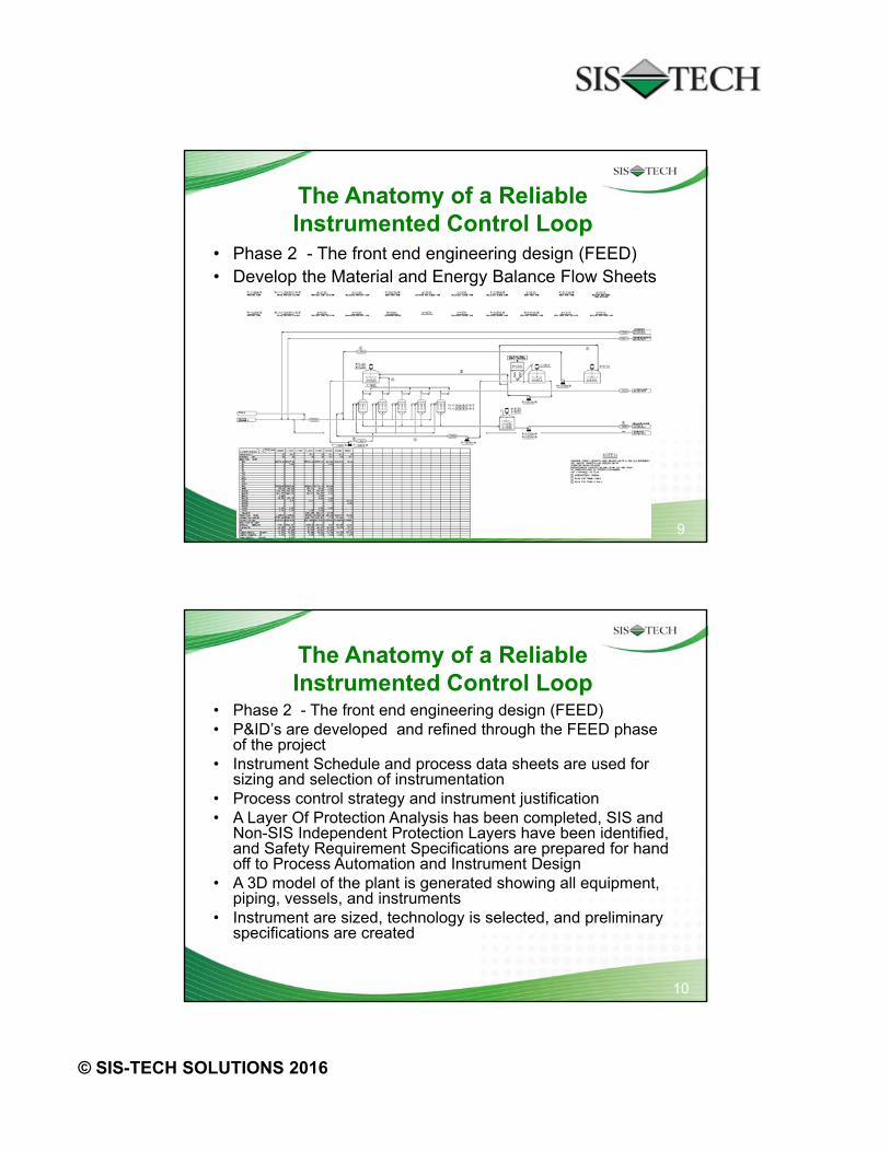
• Phase 2 - The front end engineering design (FEED)• Develop the Material and Energy Balance Flow Sheets
10
The Anatomy of a Reliable Instrumented Control Loop
• Phase 2 - The front end engineering design (FEED)• P&ID’s are developed and refined through the FEED phase
of the project• Instrument Schedule and process data sheets are used for
sizing and selection of instrumentation• Process control strategy and instrument justification• A Layer Of Protection Analysis has been completed, SIS and
Non-SIS Independent Protection Layers have been identified,and Safety Requirement Specifications are prepared for handoff to Process Automation and Instrument Design
• A 3D model of the plant is generated showing all equipment,piping, vessels, and instruments
• Instrument are sized, technology is selected, and preliminaryspecifications are created

70© SIS-TECH SOLUTIONS 2016 Symposium for the Process Industry ©©6©
11
The Anatomy of a Reliable Instrumented Control Loop
• Phase 2 - The front end engineering design (FEED)• What should go right?• Process Engineering should work closely with Plant
Owners and all Engineering Disciplines to develop andrefine the P&ID’s
• The instrument technology should be known to ensurecorrect line size and optimum location/placement
• Consideration should be given as to how an instrumentwill be isolated, cleared, and tested or replaced
• ALL changes should be communicated and evaluated forpotential impact to all disciplines
• Any changes made after FEED can have a significantimpact on overall project costs
12
The Anatomy of a Reliable Instrumented Control Loop
• Phase 2 - The front end engineering design (FEED)• What Can Go Wrong?• Suboptimal installations
– Insufficient straight pipe runs can cause flow meter inaccuracy– Flow meter placed in a high spot in the line– Control valve located with a 90 pipe fitting close coupled downstream– Thermowell subjected to excessive turbulence or not able to provide
accurate measurement• No way to replace, repair, or test the device without shutting down
– Bypasses around instruments or valves are overlooked– Instrument not accessible for maintenance
• Inaccurate process data can result in the selection of the wrongmeasurement technology or incorrectly sized instruments

70© SIS-TECH SOLUTIONS 2016 Symposium for the Process Industry ©©7©
13
The Anatomy of a Reliable Instrumented Control Loop
14
The Anatomy of a Reliable Instrumented Control Loop
• Phase 3 - Detail Design• At this phase all the hard work and deliverables generated during
the FEED phase are handed over to Design Engineering• Key work products of the Detail Design phase include:
– Complete the engineering documents and specifications needed forprocurement
– Finalize project specific job instructions for construction– Update schedule, cost, and scope/criteria
• Disciplines/Roles involved:• --Business/plant owners (Manufacturing Reps; Project Manager)• --Project Engineering--Process Automation --Process Engineering• --Mechanical --Loss Prevention --Piping• --Maintenance/Reliability --Instrumentation --Operations• --Electrical --Procurement --Supplier Liaisons

70© SIS-TECH SOLUTIONS 2016 Symposium for the Process Industry ©©8©
15
The Anatomy of a Reliable Instrumented Control Loop
• Phase 3 - Detail Design• P&IDs are finalized• Updated 3D plant model• Process control automation code and simulation• Sizing and selection of instrumentation is completed• Equipment, Piping, Insulation, and Instrument specifications are
finalized• Safety Requirement Specifications are checked for compliance and
updated as needed• Wiring schedules/drawings, installation details, and job instructions• Cost estimates and project schedules are updated• Procurement• Equipment Protection Plan
16
The Anatomy of a Reliable Instrumented Control Loop
• Phase 3 - Detail Design• What should go right?• P&IDs are up to date and any special instructions
regarding design constraints have been incorporated• 3D model is up to date and has been thoroughly
reviewed• Operations and Man Reps have provided input to
process automation code• Maintenance/Reliability have provided input on Detail
Design deliverables• Any changes that needed to be made have been clearly
communicated and reviewed. No surprises.

70© SIS-TECH SOLUTIONS 2016 Symposium for the Process Industry ©©9©
17
The Anatomy of a Reliable Instrumented Control Loop
• Phase 3 - Detail Design• What Can Go Wrong?• Instrument specified will not meet reliability,
availability, or maintainability• Loop wiring can be the cause of many reliability
problems• Installed performance of the instrument will not
meet the required• You set construction up for failure due to
inadequate details and instructions
18
The Anatomy of a Reliable Instrumented Control Loop

70© SIS-TECH SOLUTIONS 2016 Symposium for the Process Industry ©©10©
19
The Anatomy of a Reliable Instrumented Control Loop
• Phase 4 - Construction• The basic goal of this phase is to delivery a facility that is physically
and procedurally ready for startup activities.• Key work products of the Construction phase include:
– Delivered equipment– A constructed facility– Completed construction documents
• Disciplines/Roles involved:• --Business/plant owners (Manufacturing Reps; Project Manager)• --Project Engineering --Process Automation --Process Engineering• --Mechanical --Loss Prevention --Piping• --Maintenance/Reliability --Instrumentation --Electrical• --Procurement --Supplier Liaisons --Construction Mgr• --Construction Workers --Warehouse Receiving --Inspectors
20
The Anatomy of a Reliable Instrumented Control Loop
• Phase 4 – Construction• A construction contractor is selected and has the construction
package• Instrumentation and associated hardware is received and stored• Wiring and associated raceways are installed• Instrumentation is relocated to construction site just prior to
installation• Instruments are installed once piping is installed and tested and
vessels are in place• Instrument wiring is terminated• The final installation is inspected to ensure it has been installed per
installation details and job instructions• Loop verification or functional loop checks may be required at this
point• Changes made during construction phase are captured (As-built)

70© SIS-TECH SOLUTIONS 2016 Symposium for the Process Industry ©©11©
21
The Anatomy of a Reliable Instrumented Control Loop
• Phase 4 - Construction• What should go right?• You selected a qualified contractor with skilled workforce• Instrumentation is properly protected from the time it is
received until it is placed into service• Good document management practices• Instruments & wiring are installed at the proper time and per
details• Termination – drawings were correct, completed per drawing,
no damage• Inspectors are qualified, know what to look for, and found all
deficiencies• All changes were documented and drawings updated
22
The Anatomy of a Reliable Instrumented Control Loop
So what could possibly go wrong during construction?
70© SIS-TECH SOLUTIONS 2016 Symposium for the Process Industry ©©12©
23
The Anatomy of a Reliable Instrumented Control Loop
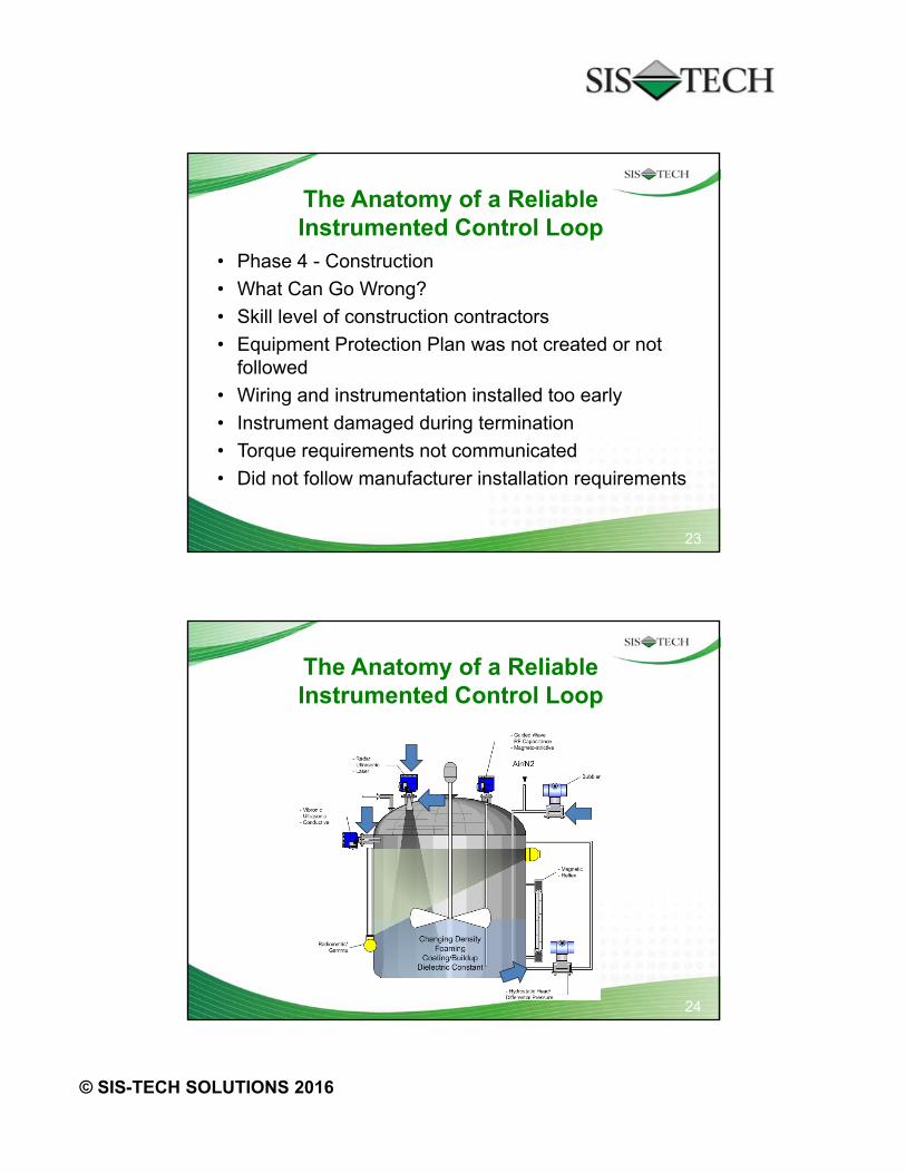
• Phase 4 - Construction
• What Can Go Wrong?
• Skill level of construction contractors
• Equipment Protection Plan was not created or notfollowed
• Wiring and instrumentation installed too early
• Instrument damaged during termination
• Torque requirements not communicated
• Did not follow manufacturer installation requirements
24
The Anatomy of a Reliable Instrumented Control Loop

70© SIS-TECH SOLUTIONS 2016 Symposium for the Process Industry ©©13©
25
The Anatomy of a Reliable Instrumented Control Loop
• Phase 5• Commissioning/Start-Up
• Disciplines/Roles involved:• --Business/plant owners (Manufacturing Reps; Project Manager)• --Project Engineering --Process Automation --Process Engineering• --Mechanical --Loss Prevention --Piping• --Maintenance/Reliability --Instrumentation --Electrical• --Plant Operations --Supplier Liaisons --Construction Mgr• --Training Coordinators --Commissioning Team
• What should go right:• What can go wrong:
26
The Anatomy of a Reliable Instrumented Control Loop
• Phase 5• Commissioning / Start-Up• The sequence of events that occur just prior to
producing product is the commissioning phase.• Defined early in the project phase to allow for proper
scheduling of all phases of the project• Requires a systematic detailed process to verify all
preparation work, checks and reviews arecompleted prior to making product
• Requires a formalized turnover process fromcontractor to commissioning team
70© SIS-TECH SOLUTIONS 2016 Symposium for the Process Industry ©©14©
27
The Anatomy of a Reliable Instrumented Control Loop
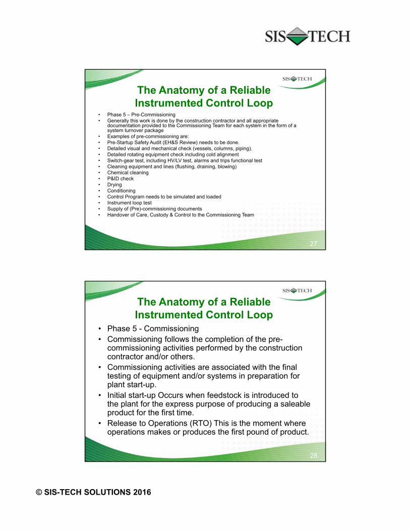
• Phase 5 – Pre-Commissioning• Generally this work is done by the construction contractor and all appropriate
documentation provided to the Commissioning Team for each system in the form of asystem turnover package
• Examples of pre-commissioning are:• Pre-Startup Safety Audit (EH&S Review) needs to be done.• Detailed visual and mechanical check (vessels, columns, piping).• Detailed rotating equipment check including cold alignment• Switch-gear test, including HV/LV test, alarms and trips functional test• Cleaning equipment and lines (flushing, draining, blowing)• Chemical cleaning• P&ID check• Drying• Conditioning• Control Program needs to be simulated and loaded• Instrument loop test• Supply of (Pre)-commissioning documents• Handover of Care, Custody & Control to the Commissioning Team
28
The Anatomy of a Reliable Instrumented Control Loop
• Phase 5 - Commissioning• Commissioning follows the completion of the pre-
commissioning activities performed by the constructioncontractor and/or others.
• Commissioning activities are associated with the finaltesting of equipment and/or systems in preparation forplant start-up.
• Initial start-up Occurs when feedstock is introduced tothe plant for the express purpose of producing a saleableproduct for the first time.
• Release to Operations (RTO) This is the moment whereoperations makes or produces the first pound of product.

70© SIS-TECH SOLUTIONS 2016 Symposium for the Process Industry ©©15©
29
The Anatomy of a Reliable Instrumented Control Loop
• Phase 5 – Commissioning/Start-up• What should go right?• All equipment should come online in proper sequence• Lines were properly cleaned and flushed and brought up to
proper temp before process introduced• Process program works as designed to start and run plant• Design/equipment problems were discovered during design
and construction• Problems encountered are taken care of as met• Documentation updated per incident• Documentation is completed and communicated to all parties
and finally documentation is submitted to libraries• Process is introduced and plant runs as desired
30
The Anatomy of a Reliable Instrumented Control Loop
• Phase 5 – Commissioning/Start-up• What Can Go Wrong?• Miscommunication between design and manufacturing
causes incompatibility of process and constructionmaterials
• Incomplete documentation results in incorrect valuesused in process programming
• Incomplete documentation or miscommunication fromprevious project causes repeat of problem inconstruction design or incorrect instrumentation orimproperly sized equipment, etc
• Major rebuilds cause significant delays in constructionand start up at considerable cost to business

70© SIS-TECH SOLUTIONS 2016 Symposium for the Process Industry ©©16©
31
The Anatomy of a Reliable Instrumented Control Loop
• Phase 6• Continuing Operations• Disciplines/Roles involved:• --Business/plant owners (Manufacturing Reps; Project Manager)• --Project Engineering --Process Automation --Process Engineering• --Plant Operations --Loss Prevention --Work Planner• --Maintenance/Reliability --Instrumentation --Electrical• --Procurement --Supplier Liaisons --I/E/A Design Leads• --Training Coordinators --Maintenance Leader
• What should go right:• What can go wrong:
32
The Anatomy of a Reliable Instrumented Control Loop
• Phase 6 - Operations and Life Cycle Maintenance• Project Man Rep works with Project Maintenance Rep and Project
IEA Design Lead to ensure specified data components are completein the tool preferred and ready for transfer
• Examples of what can go wrong:• Not having a place to track your data• Not following process and documentation “SIS Instrumentation,
Electrical, Analyzer”• Make sure visual inspections are performed after equipment is
insulated or painted. Why? Certain temperature points ofinstrumentation will read higher or lower. Vents on valves andinstruments can be plugged (will be).
• Instrumentation can be insulated causing failure of device• Valve stem can be painted preventing proper operation or tape on
stem to protect from paint is left on preventing proper operation

70© SIS-TECH SOLUTIONS 2016 Symposium for the Process Industry ©©17©
33
The Anatomy of a Reliable Instrumented Control Loop
• Phase 6 - Operations and Life Cycle Maintenance• Life Cycle Maintenance and Purpose of Reliability Data• In order to improve safe operation and cost performance, reliability
engineering and technology centers need information extracted out ofpreferred tools to make data based decisions. The decisions will impactplant reliability, availability, maintainability and safety by:
• Tracking the number of IEA incidents and their cost during commissioning• Tracking the number of IEA incidents and their cost during normal operating
plant life cycle• Determining which IEA components have a higher “infant mortality rate”• Determining failure rate per type of IEA device/equipment• Determining failure rate per type of IEA device/equipment per particular
process application• Optimizing the preventive maintenance or proof test interval that provides
the benefit of the preventive maintenance proof test activity versus the riskof unplanned failures
• Insuring robust design of SIS configuration to prevent spurious plant tripsbut insure availability when demanded
34
The Anatomy of a Reliable Instrumented Control Loop
• Feedback and Learning’s for ContinuousImprovement
• What should go right:• What can go wrong:• What did you learn?• Because commissioning activities are critical and
therefore schedule driven, the pre selection ofpriorities for all commissioning & start-up systemsare of the utmost importance to the schedule. Timeand effort must be given early to the proper planningfor the commissioning of a new plant as well as aReliable Instrumented Control Loop.

70© SIS-TECH SOLUTIONS 2016 Symposium for the Process Industry ©©18©
35
ABOUT THE PRESENTERS
36
Will Brooks
• 1972 Texas Southern University BS degree inElectronics and Industrial Education
• 42 years experience Dow Chemical– Currently Sr. Technologist Leader I/E/A– SIS Coach/SME Dow Freeport and member of Dow global
network– Instructor for SIS/BPCS Maintenance and Engineering– Past Dow focal point to S&B Engineers and Constructors– Past Instrument Engineering Lead Designer– Certified Six Sigma Black Belt– Lake Jackson, TX City Council Member– ISA member of long standing– Society of Packaging and Handling Engineers– Associate member of National Society of Professional Engineers

70© SIS-TECH SOLUTIONS 2016 Symposium for the Process Industry ©©19©
37
Patrick Skweres, P.E.
• 1978 BSME Texas A&M University• 5 years SIS-TECH Solutions—Present Senior consultant
SIS and Instrument Reliability• 31 years Dow Chemical
– Global Instrument Reliability Leader– Member Global SIS Implementation Team– Texas Operations Instrument Process Leader– Texas Operation Instrument Engineering Section Leader– Certified Six Sigma Black Belt– ISA member in long standing– Certified Safety Engineer– Member CCPS Process Equipment Reliability Database– Member Materials Technology Institute—Instrument Reliability
38
Dennis Wood
• AAS Instrument Technology• 25 Years Dow Chemical
– Sr. Instrument Technology Leader– Instrument SME for Dow Chlor-Vinyl Tech Center– Instrument Manufacturing Rep. on world-scale membrane
chlorine plant involved or leading particular phases of theproject including liaison to multinational EPC: front end loading,detailed design, commissioning, start-up
– Certified Six Sigma Black Belt– Member Dow Global Pressure Technology Resource Network– Member Dow SIS Technology Resource Network– Instrument Discipline Activity Specialist for Freeport and Texas
City– ISA member in long standing