Prepared by Dr. M.Vinoth - kanchiuniv.ac.in
63
LECTURE NOTES ON ROBOTICS AND AUTOMATION Prepared by Dr. M.Vinoth DEPARTMENT OF ELECTRONICS AND COMMUNICATION ENGINEERING
Transcript of Prepared by Dr. M.Vinoth - kanchiuniv.ac.in

LECTURE NOTES
ON
ROBOTICS AND AUTOMATION
Prepared by
Dr. M.Vinoth
DEPARTMENT OF ELECTRONICS AND COMMUNICATION
ENGINEERING

UNIT-I
Pre-requisite:
To study the various parts of robots and fields of robotics.
OUTCOMES:
Analyze the basic concepts of working of robot.
INTRODUCTION
The field of robotics has its origins in science fiction. The term robot was derived from the English translation
of a fantasy play written in Czechoslovakia around 1920. It took another 40 years before the modern technology
of industrial robotics began. Today Robots are highly automated mechanical manipulators controlled by
computers. We survey some of the science fiction stories about robots, and we trace the historical development
of robotics technology. Let us begin our chapter by defining the term robotics and establishing its place in
relation to other types of industrial automation.
Robotics: -
Robotics is an applied engineering science that has been referred to as a combination of machine tool
technology and computer science. It includes machine design, production theory, micro electronics, computer
programming & artificial intelligence.
Industrial robot: -
The official definition of an industrial robot is provided by the robotics industries association (RIA). Industrial
robot is defined as an automatic, freely programmed, servo-controlled, multi-purpose manipulator to handle
various operations of an industry with variable programmed motions.
Automation and robotics:-
Automation and robotics are two closely related technologies. In an industrial context, we can dean automation
as a technology that is concerned with the use of mechanical, electronic, and computer-based systems in the
operation and control of production Examples of this technology include transfer lines. Mechanized assembly
machines, feedback control systems (applied to industrial processes), numerically controlled machine tools, and
robots. Accordingly, robotics is a form of industrial automation.
Ex:- Robotics, CAD/CAM, FMS, CIMS
Types of Automation:-
Automation is categorized into three types. They are,
1)Fixed Automation
2) Programmable Automation
3) Flexible Automation
(1) Fixed Automation
It is the automation in which the sequence of processing or assembly operations to be carried out is fixed by the
equipment configuration. In fixed automation, the sequence of operations (which are simple) are integrated in a
piece of equipment. Therefore, it is difficult to automate changes in the design of the product. It is used where
high volume of production is required Production rate of fixed automation is high. In this automation, no new
products are processed for a given sequence of assembly operations.
Features:-
i) High volume of production rates,
ii) Relatively inflexible in product variety (no new products are produced). Ex:- Automobile industries … etc.
(2) Programmable Automation
It is the automation in which the equipment is designed to accommodate various product configurations in order
to change the sequence of operations or assembly operations by means of control program. Different types of
programs can be loaded into the equipment to produce products with new configurations (i.e., new products). It
is employed for batch production of low and medium volumes. For each new batch of different configured
product, a new control program corresponding to the new product is loaded into the equipment. This automation
is relatively economic for small batches of the product.
Features:-
i) High investment in general purpose,
ii) Lower production rates than fixed automation,
iii) Flexibility & Changes in products configuration,
iv) More suitable for batch production.
Ex:- Industrial robot, NC machines tools… etc.
(3) Flexible Automation
A computer integrated manufacturing system which is an extension of programmable automation is referred as
flexible automation. It is developed to minimize the time loss between the changeover of the batch production
from one product to another while reloading. The program to produce new products and changing the physical
setup i.e., it
produces different products with no loss of time. This automation is more flexible in interconnecting work
stations with material handling and storage system.
Features:-
i) High investment for a custom engineering system.
ii) Medium Production rates
iii) Flexibility to deal with product design variation,
iv) Continuous production of variable mixtures of products. Ex:- Flexible manufacturing systems (FMS)

Advantages:-
1.High Production rates
2. Lead time decreases
3. Storing capacity decreases
4. Human errors are eliminated.
5. Labour cost is decreases.
Disadvantages:-
1.Initial cost of raw material is very high,
2. Maintenance cost is high,
3. Required high skilled Labour.
4. Indirect cost for research development & programming increases.
Reasons for implementation of automated systems in manufacture industries:-
The reasons for the implementation of automated systems in manufacturing industries are as follows,
(i) To Increase the Productivity Rate of Labour
(ii) To Decrease the Cost of Labour
(iii) To Minimize the Effect of Shortage of Labour
(iv) To Obtain High Quality of Products
(v) A Non-automation nigh Cost is Avoided
(vi) To Decrease the Manufacturing Lead Time
(vii) To upgrade the Safety of Workers.
Need for using robotics in industries:-
Industrial robot plays a significant role in automated manufacturing to perform different kinds of applications.
1. Robots can be built a performance capability superior to those of human beings. In terms of strength, size,
speed, accuracy…etc.
2. Robots are better than humans to perform simple and repetitive tasks with better quality and consistence’s.
3. Robots do not have the limitations and negative attributes of human works .such as fatigue, need for rest, and
diversion of attention…..etc.
4. Robots are used in industries to save the time compared to human beings.
5. Robots are in value poor working conditions
CAD/CAM & Robotics:-
CAD/CAM is a term which means computer aided design and computer aided manufacturing. It is the
technology concerned with the use of digital computers to perform certain functions in design & production.
CAD:- CAD can be defined as the use of computer systems to assist in the creation modification, analysis OR
optimization of design.
Cam:- CAM can be defined as the use of computer system to plan, manage & control the operation of a
manufacturing plant, through either direct or in direct computer interface with the plant’s production resources.
Specifications of robotics:-
1.Axil of motion
2. Work stations
3. Speed
4. Acceleration
5. Pay load capacity
6. Accuracy
7. Repeatability etc…
Overview of Robotics:-
"Robotics" is defined as the science of designing and building Robots which are suitable for real life application
in automated manufacturing and other non-manufacturing environments. It has the following objectives,
1.To increase productivity
2. Reduce production life
3. Minimize labour requirement
4. Enhanced quality of the products
5. Minimize loss of man hours, on account of accidents.
6. Make reliable and high speed production.
Types of drive systems:-
1. Hydraulic drive
2. Electric drive
3. Pneumatic drive

1. Hydraulic drive:-
Hydraulic drive and electric drive arc the two main types of drives used on more sophisticated robots.
Hydraulic drive is generally associated with larger robots, such as the Unimate 2000 series. The usual
advantages of the hydraulic drive system are that it provides the robot with greater speed and strength. The
disadvantages of the hydraulic drive system are that it typically adds to the floor space required by the robot,
and that a hydraulic system is inclined to leak on which is a nuisance.
This type of system can also be called as non-air powered cylinders. In this system, oil is used as a working
fluid instead of compressed air. Hydraulic system need pump to generate the required pressure and flow rate.
These systems are quite complex, costly and require maintenance.
2. Electric drive:-
Electric drive systems do not generally provide as much speed or power as hydraulic systems. However, the
accuracy and repeatability of electric drive robots are usually better. Consequently, electric robots tend to be
smaller. Require less floor space, and their applications tend toward more precise work such as assembly.
In this System, power is developed by an electric current. It required little maintenance and the operation is
noise less.
3. Pneumatic drive:-
Pneumatic drive is generally reserved for smaller robots that possess fewer degrees of freedom (two- to four-
joint motions).
In this system, air is used as a working fluid, hence it is also called air-powered cylinders. Air is compressed in
the cylinder with the aid of pump the compressed air is used to generate the power with required amount of
pressure and flow rates.
Applications of robots:-
Present Applications of Robots:-
(i) Material transfer applications
(ii) Machine loading and unloading
(iii) Processing operations like,
(a) Spot welding
(b) Continuous arc welding
(c) Spray coating
(d) Drilling, routing, machining operations
(e) Grinding, polishing debarring wire brushing
(g) Laser drilling and cutting etc.
(iv) Assembly tasks, assembly cell designs, parts mating.
(v) Inspection, automation.

Future Applications of Robots:-
The profile of the future robot based on the research activities will include the following,
(i) Intelligence
(ii) Sensor capabilities
(iii) Telepresence
(iv) Mechanical design
(v) Mobility and navigation (walking machines)
(vi) Universal gripper
(vii) Systems and integration and networking
(viii) FMS (Flexible Manufacturing Systems)
(Ix) Hazardous and inaccessible non-manufacturing environments
(x) Underground coal mining
(xi) Fire fighting operations
(xii) Robots in space
(xiii) Security guards
(xiv) Garbage collection and waste disposal operations
(xv) Household robots
(xvi) Medical care and hospital duties etc.
Asimov's laws of robotics
The Three Laws of Robotics or Asimov's Laws are a set of rules devised by the science fiction author Isaac
Asimov
First Law - A robot may not injure a human being or, through inaction, allow a human being to come to harm.
Second Law - A robot must obey the orders given it by human beings except where such orders would conflict
with the First Law.
Third Law - A robot must protect its own existence as long as such protection does not conflict with the First or
Second Laws.
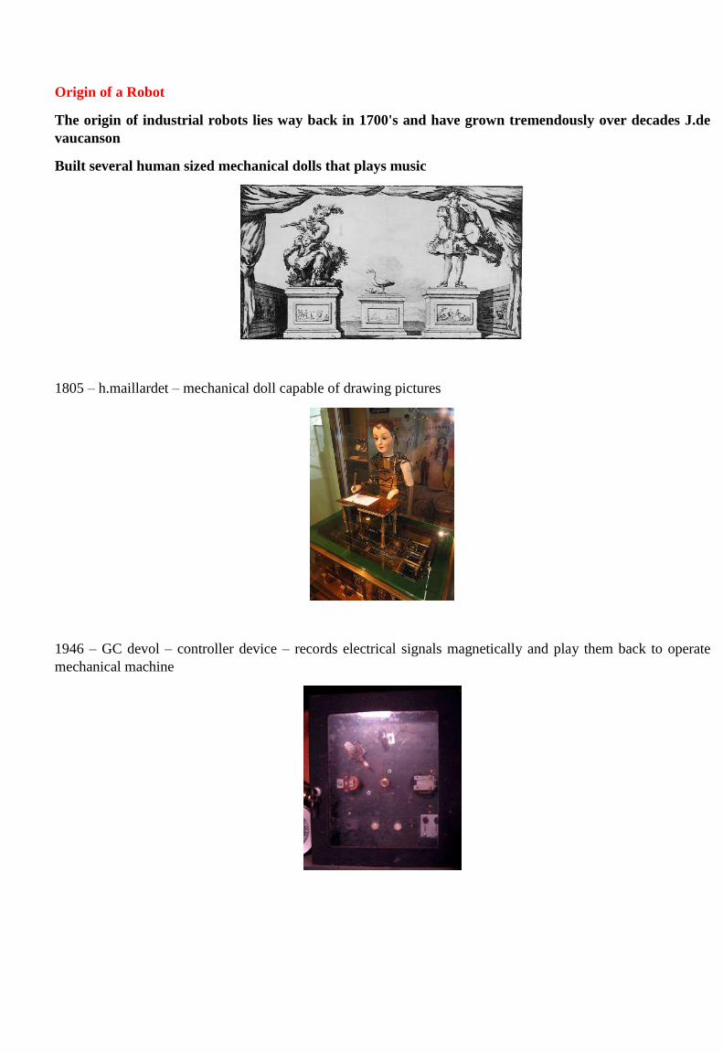
Origin of a Robot
The origin of industrial robots lies way back in 1700's and have grown tremendously over decades J.de
vaucanson
Built several human sized mechanical dolls that plays music
1805 – h.maillardet – mechanical doll capable of drawing pictures
1946 – GC devol – controller device – records electrical signals magnetically and play them back to operate
mechanical machine
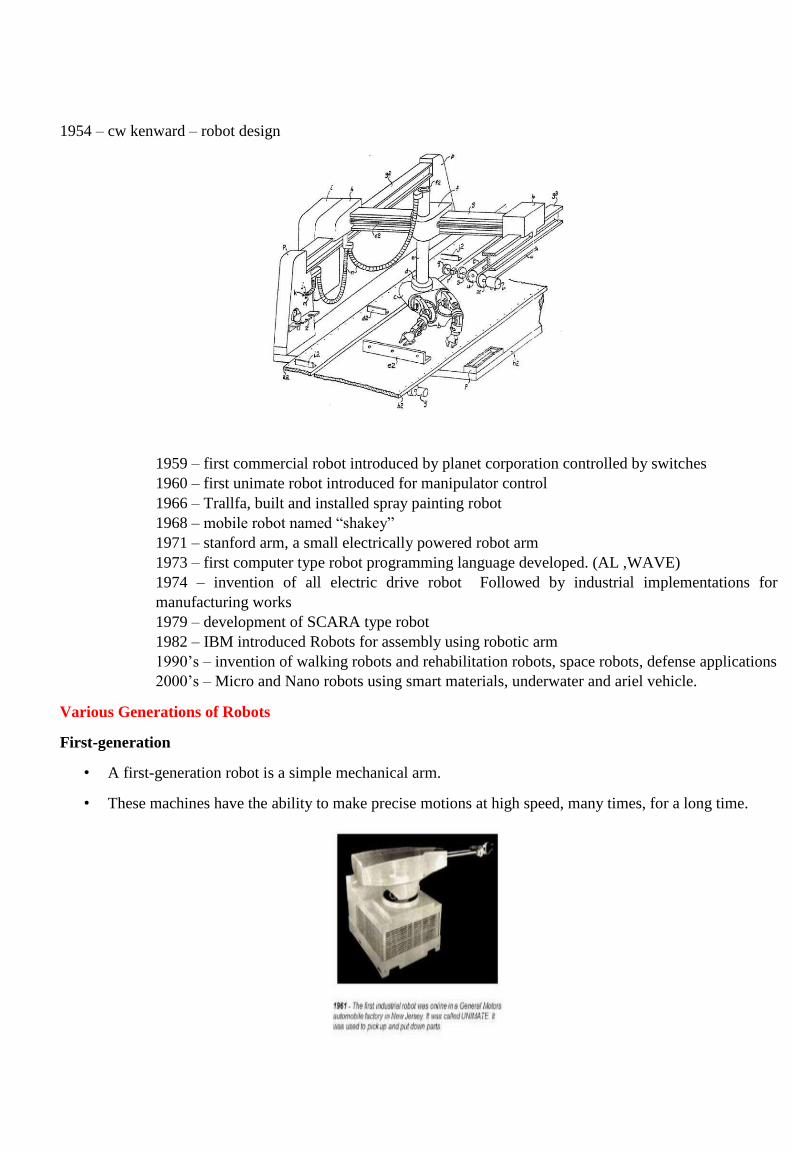
1954 – cw kenward – robot design
1959 – first commercial robot introduced by planet corporation controlled by switches
1960 – first unimate robot introduced for manipulator control
1966 – Trallfa, built and installed spray painting robot
1968 – mobile robot named “shakey”
1971 – stanford arm, a small electrically powered robot arm
1973 – first computer type robot programming language developed. (AL ,WAVE)
1974 – invention of all electric drive robot Followed by industrial implementations for
manufacturing works
1979 – development of SCARA type robot
1982 – IBM introduced Robots for assembly using robotic arm
1990’s – invention of walking robots and rehabilitation robots, space robots, defense applications
2000’s – Micro and Nano robots using smart materials, underwater and ariel vehicle.
Various Generations of Robots
First-generation
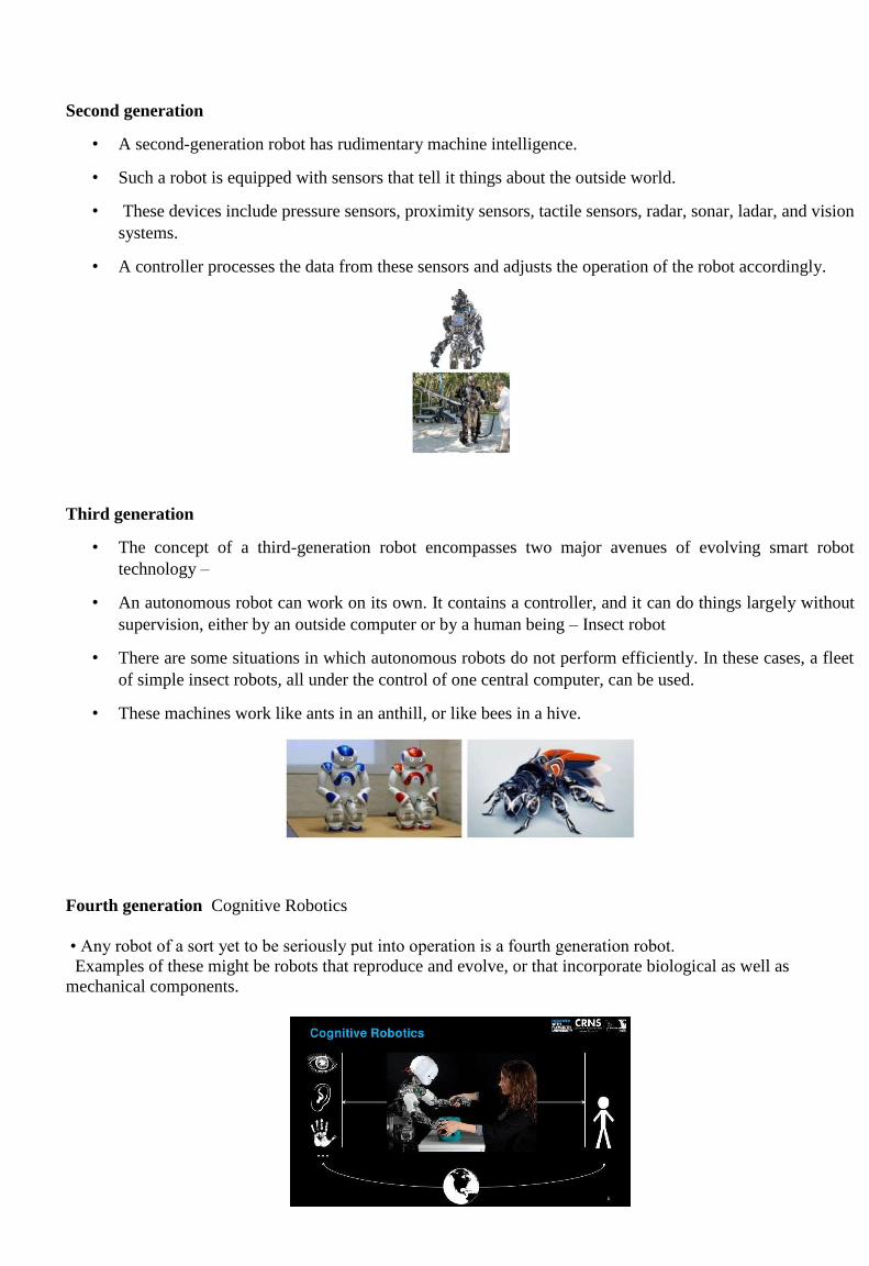
• A first-generation robot is a simple mechanical arm.
• These machines have the ability to make precise motions at high speed, many times, for a long time.
Second generation
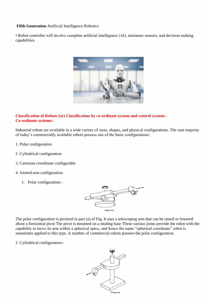
• A second-generation robot has rudimentary machine intelligence.
• Such a robot is equipped with sensors that tell it things about the outside world.
• These devices include pressure sensors, proximity sensors, tactile sensors, radar, sonar, ladar, and vision
systems.
• A controller processes the data from these sensors and adjusts the operation of the robot accordingly.
Third generation
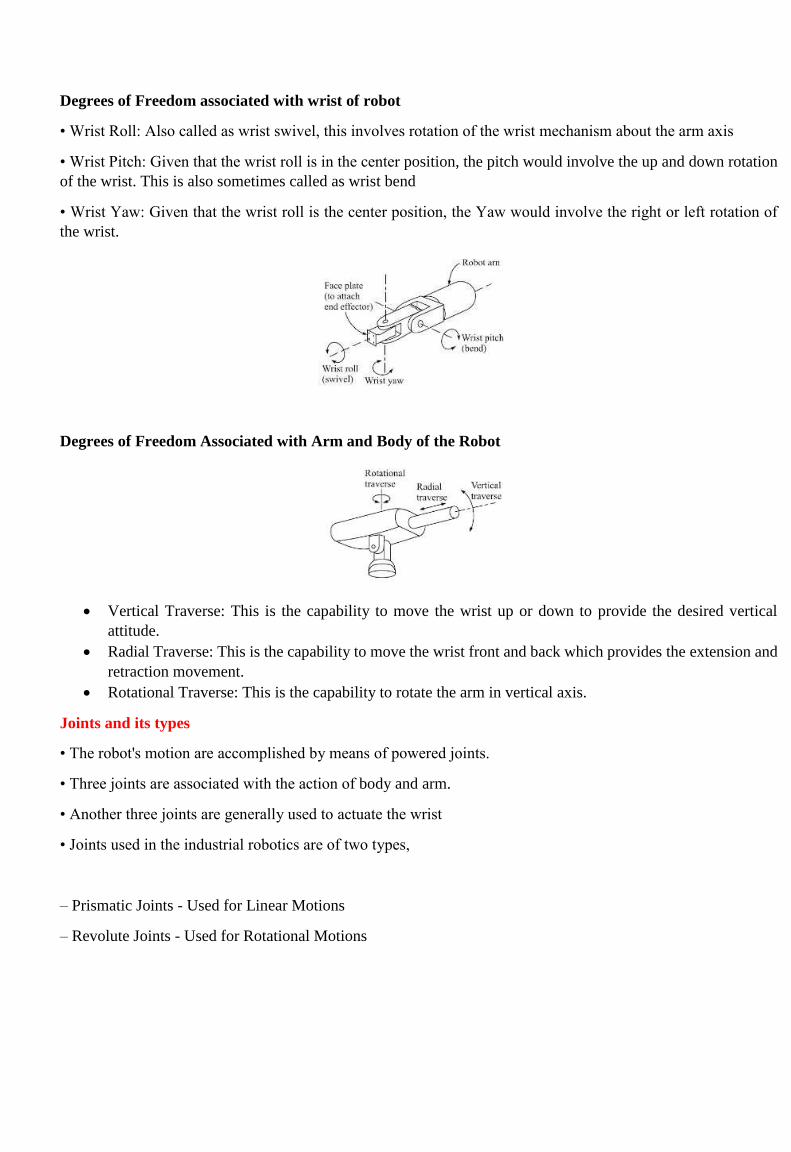
• The concept of a third-generation robot encompasses two major avenues of evolving smart robot
technology –
• An autonomous robot can work on its own. It contains a controller, and it can do things largely without
supervision, either by an outside computer or by a human being – Insect robot
• There are some situations in which autonomous robots do not perform efficiently. In these cases, a fleet
of simple insect robots, all under the control of one central computer, can be used.
• These machines work like ants in an anthill, or like bees in a hive.
Fourth generation Cognitive Robotics
• Any robot of a sort yet to be seriously put into operation is a fourth generation robot.
Examples of these might be robots that reproduce and evolve, or that incorporate biological as well as
mechanical components.
Fifth Generation Artificial Intelligence Robotics
• Robot controller will involve complete artificial intelligence (AI), miniature sensors, and decision making
capabilities.
Classification of Robots (or) Classification by co-ordinate system and control system:-
Co-ordinate systems:-
Industrial robots are available in a wide variety of sizes, shapes, and physical configurations. The vast majority
of today’s commercially available robots possess one of the basic configurations:
1. Polar configuration
2. Cylindrical configuration
3. Cartesian coordinate configurable
4. Jointed-arm configuration
1. Polar configuration:-
The polar configuration is pictured in part (a) of Fig. It uses a telescoping arm that can be raised or lowered
about a horizontal pivot The pivot is mounted on a mta6ng base These various joints provide the robot with the
capability to move its arm within a spherical space, and hence the name “spherical coordinate” robot is
sometimes applied to this type. A number of commercial robots possess the polar configuration.
2. Cylindrical configuration:-

The cylindrical configurable, as shown in fig, uses a vertical column and a slide that can be moved up or down
along the column. The robot arm is attached to the slide so that it cm he moved radially with respect to the column.
By routing the column, the robot is capable of achieving a work space that approximation a cylinder.
3. Cartesian coordinate configurable:-
The cartesian coordinate robot, illustrated in part Cc) of Fig, uses three perpendicular slides to construct the x, y,
and z axes. Other names are sometimes applied W this configuration, including xyz robot and rectilinear robot,
By moving the three slides relative to one another, the robot is capable of operating within a rectangular work
envelope.
4. Jointed-arm configuration:-
The jointed-arm robot is pictured in Fig. Its configuration is similar to that of the human arm. It consists of two
straight components. Corresponding to the human forearm and upper arm, mounted on a vertical pedestal. These
components are connected by two rotary joints corresponding to the shoulder and elbow.
Degrees of freedom
Industrial robots are designed to perform productive work such as pick and place, welding, assembly, etc., the
work is accomplished by enabling the robot to move its body, arm and wrist through a series of motion and
positions. The individual joint motions associated with the performance of a task are referred to by the term
Degrees of Freedom (DOF) "Degrees of freedom, in a mechanics context, are specific, defined modes in which a
mechanical device or system can move. The number of degrees of freedom is equal to the total number of
independent displacements or aspects of motion."
Working envelope– an envelope is the region of space a robot can reach during its normal range of motion.
Degrees of Freedom associated with wrist of robot
• Wrist Roll: Also called as wrist swivel, this involves rotation of the wrist mechanism about the arm axis
• Wrist Pitch: Given that the wrist roll is in the center position, the pitch would involve the up and down rotation
of the wrist. This is also sometimes called as wrist bend
• Wrist Yaw: Given that the wrist roll is the center position, the Yaw would involve the right or left rotation of
the wrist.
Degrees of Freedom Associated with Arm and Body of the Robot
Vertical Traverse: This is the capability to move the wrist up or down to provide the desired vertical
attitude.
Radial Traverse: This is the capability to move the wrist front and back which provides the extension and
retraction movement.
Rotational Traverse: This is the capability to rotate the arm in vertical axis.
Joints and its types
• The robot's motion are accomplished by means of powered joints.
• Three joints are associated with the action of body and arm.
• Another three joints are generally used to actuate the wrist
• Joints used in the industrial robotics are of two types,
– Prismatic Joints - Used for Linear Motions
– Revolute Joints - Used for Rotational Motions
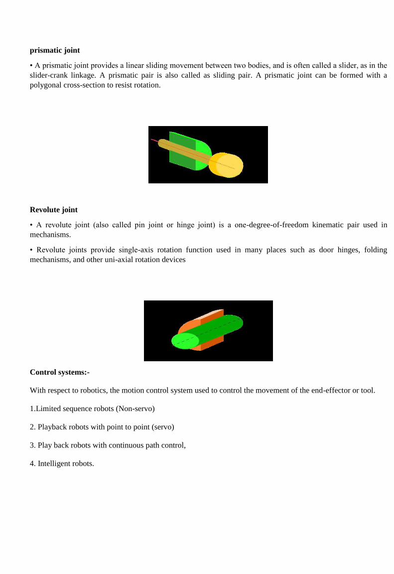
prismatic joint
• A prismatic joint provides a linear sliding movement between two bodies, and is often called a slider, as in the
slider-crank linkage. A prismatic pair is also called as sliding pair. A prismatic joint can be formed with a
polygonal cross-section to resist rotation.
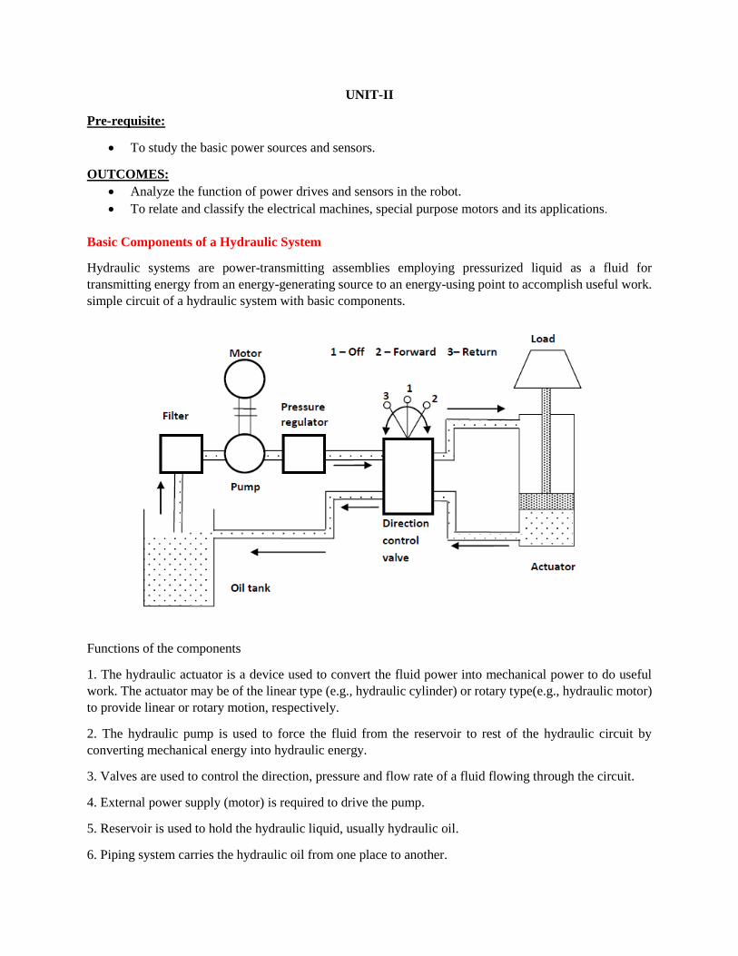
Revolute joint
• A revolute joint (also called pin joint or hinge joint) is a one-degree-of-freedom kinematic pair used in
mechanisms.
• Revolute joints provide single-axis rotation function used in many places such as door hinges, folding
mechanisms, and other uni-axial rotation devices
Control systems:-
With respect to robotics, the motion control system used to control the movement of the end-effector or tool.
1.Limited sequence robots (Non-servo)
2. Playback robots with point to point (servo)
3. Play back robots with continuous path control,
4. Intelligent robots.

Limited sequence robots (Non-servo):-
Limited sequence robots do not give servo controlled to inclined relative positions of the joints; instead they are
controlled by setting limit switches & are mechanical stops. There is generally no feedback associated with a
limited sequence robot to indicate that the desired position, has been achieved generally thin type of robots
involves simple motion as pick & place operations.
Point to point motion:-
These type robots are capable of controlling velocity acceleration & path of motion, from the beginning to the
end of the path. It uses complex control programs, PLC’s (programmable logic controller’s) computers to
control the motion.
The point to point control motion robots are capable of performing motion cycle that consists of a series of
desired point location. The robot is tough & recorded, unit.
Continuous path motion:-
In this robots are capable of performing motion cycle in which the path followed by the robot in controlled. The
robot move through a series of closely space point which describe the desired path.
Ex:- Spray painting, arc welding & complicate assembly operations.
Intelligent robots:-
This type of robots not only programmable motion cycle but also interact with its environment in a way that
years intelligent. It taken make logical decisions based on sensor data receive from the operation.
There robots are usually programmed using an English like symbolic language not like a computer
programming language.
Precision of movement (or) parameters of robot:-
The preceding discussion of response speed and stability is concerned with the dynamic performance of the
robot. Another measure of performance is precision of the robot's movement. We will define precision as a
function of three features:
1.Spatial resolution
2. Accuracy
3. Repeatability
These terms will be defined with the following assumptions.
1) The definitions will apply at the robot’s wrist end with no hand attached to the wrist.
2) The terms apply to the worst case conditions, the conditions under which the robot's precision will be at its
wont. This generally means that the robot’s arm is fully extended in the case of a jointed arm or polar
configurable.
3) Third, our definitions will he developed in the context of a point-to-point robot.

1. Spatial resolution:-
The spatial resolution of a robot is the smallest increment of movement into which the robot can divide its work
volume. Spatial resolution depends on two factors: the system's control resolution and the robot's mechanical
inaccuracies. It is easiest to conceptualize these factors in terms of a robot with 1 degree of freedom.
2. Accuracy:-
Accuracy refers to a robot's ability to position its wrist end at a desired target point within the work volume. The
accuracy of a robot can be denned in terms of spatial resolution because the ability to achieve a given target
point depends on how closely the robot can define the control increments for each of its joint motions.
3. Repeatability:-
Repeatability is concerned with the robot's ability to position its wrist or an end effector attached to its wrist at a
point in space is known as repeatability. Repeatability and accuracy refer to two different aspects of the robot’s
precision. Accuracy relates to the robot's capacity to be programmed to achieve a given target point. The actual
programmed point will probably be different from the target point due to limitations of control resolution
Repeatability refers to the robot’s ability to return to the programmed point when commanded to do so.
UNIT-II
Pre-requisite:
To study the basic power sources and sensors.
OUTCOMES:
Analyze the function of power drives and sensors in the robot.
To relate and classify the electrical machines, special purpose motors and its applications.
Basic Components of a Hydraulic System
Hydraulic systems are power-transmitting assemblies employing pressurized liquid as a fluid for
transmitting energy from an energy-generating source to an energy-using point to accomplish useful work.
simple circuit of a hydraulic system with basic components.
Functions of the components
1. The hydraulic actuator is a device used to convert the fluid power into mechanical power to do useful
work. The actuator may be of the linear type (e.g., hydraulic cylinder) or rotary type(e.g., hydraulic motor)
to provide linear or rotary motion, respectively.
2. The hydraulic pump is used to force the fluid from the reservoir to rest of the hydraulic circuit by
converting mechanical energy into hydraulic energy.
3. Valves are used to control the direction, pressure and flow rate of a fluid flowing through the circuit.
4. External power supply (motor) is required to drive the pump.
5. Reservoir is used to hold the hydraulic liquid, usually hydraulic oil.
6. Piping system carries the hydraulic oil from one place to another.
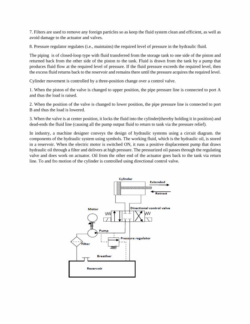
7. Filters are used to remove any foreign particles so as keep the fluid system clean and efficient, as well as
avoid damage to the actuator and valves.
8. Pressure regulator regulates (i.e., maintains) the required level of pressure in the hydraulic fluid.
The piping is of closed-loop type with fluid transferred from the storage tank to one side of the piston and
returned back from the other side of the piston to the tank. Fluid is drawn from the tank by a pump that
produces fluid flow at the required level of pressure. If the fluid pressure exceeds the required level, then
the excess fluid returns back to the reservoir and remains there until the pressure acquires the required level.
Cylinder movement is controlled by a three-position change over a control valve.
1. When the piston of the valve is changed to upper position, the pipe pressure line is connected to port A
and thus the load is raised.
2. When the position of the valve is changed to lower position, the pipe pressure line is connected to port
B and thus the load is lowered.
3. When the valve is at center position, it locks the fluid into the cylinder(thereby holding it in position) and
dead-ends the fluid line (causing all the pump output fluid to return to tank via the pressure relief).
In industry, a machine designer conveys the design of hydraulic systems using a circuit diagram. the
components of the hydraulic system using symbols. The working fluid, which is the hydraulic oil, is stored
in a reservoir. When the electric motor is switched ON, it runs a positive displacement pump that draws
hydraulic oil through a filter and delivers at high pressure. The pressurized oil passes through the regulating
valve and does work on actuator. Oil from the other end of the actuator goes back to the tank via return
line. To and fro motion of the cylinder is controlled using directional control valve.
The hydraulic system discussed above can be broken down into four main divisions that are analogous to
the four main divisions in an electrical system.
1. The power device parallels the electrical generating station.
2. The control valves parallel the switches, resistors, timers, pressure switches, relays, etc.
3. The lines in which the fluid power flows parallel the electrical lines.
4. The fluid power motor (whether it is a rotating or a non rotating cylinder or a fluid power motor) parallels
the solenoids and electrical motors.
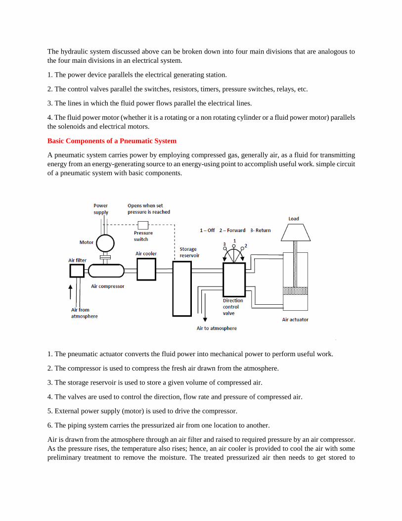
Basic Components of a Pneumatic System
A pneumatic system carries power by employing compressed gas, generally air, as a fluid for transmitting
energy from an energy-generating source to an energy-using point to accomplish useful work. simple circuit
of a pneumatic system with basic components.
1. The pneumatic actuator converts the fluid power into mechanical power to perform useful work.
2. The compressor is used to compress the fresh air drawn from the atmosphere.
3. The storage reservoir is used to store a given volume of compressed air.
4. The valves are used to control the direction, flow rate and pressure of compressed air.
5. External power supply (motor) is used to drive the compressor.
6. The piping system carries the pressurized air from one location to another.
Air is drawn from the atmosphere through an air filter and raised to required pressure by an air compressor.
As the pressure rises, the temperature also rises; hence, an air cooler is provided to cool the air with some
preliminary treatment to remove the moisture. The treated pressurized air then needs to get stored to

maintain the pressure. With the storage reservoir, a pressure switch is fitted to start and stop the electric
motor when pressure falls and reaches the required level, respectively.
The three-position change over the valve delivering air to the cylinder operates in a way similar to its
hydraulic circuit.
Electrical drives
These are direct current (DC) or alternating current (AC) servo motors. They are small in size and are easy
to control.
Electric drives are mostly used in position and speed control systems. The motors can be classified into two
groups namely DC motors and AC motors (Fig. 4.1.3). In this session we shall study the operation,
construction, advantages and limitations of DC and AC motors.
Stepper motor
A stepper motor is a pulse-driven motor that changes the angular position of the rotor in steps. Due to this
nature of a stepper motor, it is widely used in low cost, open loop position control systems.
Types of stepper motors:
• Permanent Magnet- Employ permanent magnet , Low speed, relatively high torque
• Variable Reluctance- Does not have permanent magnet, Low torque
Variable Reluctance Motor the construction of Variable Reluctance motor. The cylindrical rotor is made of soft steel and has four poles
as shown in Fig.4.2.1. It has four rotor teeth, 90⁰ apart and six stator poles, 60⁰ apart. Electromagnetic field
is produced by activating the stator coils in sequence. It attracts the metal rotor. When the windings are
energized in a reoccurring sequence of 2, 3, 1, and so on, the motor will rotate in a 30⁰ step angle. In the
non-energized condition, there is no magnetic flux in the air gap, as the stator is an electromagnet and the
rotor is a piece of soft iron; hence, there is no detent torque. This type of stepper motor is called a variable
reluctance stepper.
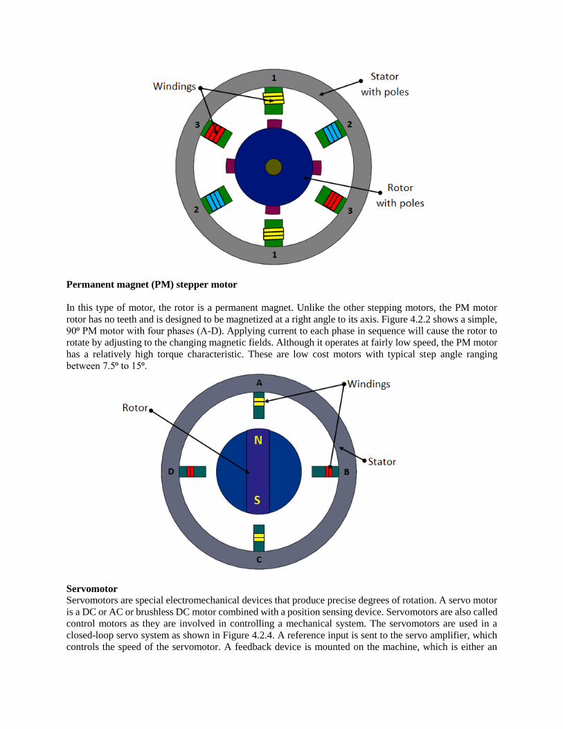
Permanent magnet (PM) stepper motor
In this type of motor, the rotor is a permanent magnet. Unlike the other stepping motors, the PM motor
rotor has no teeth and is designed to be magnetized at a right angle to its axis. Figure 4.2.2 shows a simple,
90⁰ PM motor with four phases (A-D). Applying current to each phase in sequence will cause the rotor to
rotate by adjusting to the changing magnetic fields. Although it operates at fairly low speed, the PM motor
has a relatively high torque characteristic. These are low cost motors with typical step angle ranging
between 7.5⁰ to 15⁰.
Servomotor Servomotors are special electromechanical devices that produce precise degrees of rotation. A servo motor
is a DC or AC or brushless DC motor combined with a position sensing device. Servomotors are also called
control motors as they are involved in controlling a mechanical system. The servomotors are used in a
closed-loop servo system as shown in Figure 4.2.4. A reference input is sent to the servo amplifier, which
controls the speed of the servomotor. A feedback device is mounted on the machine, which is either an
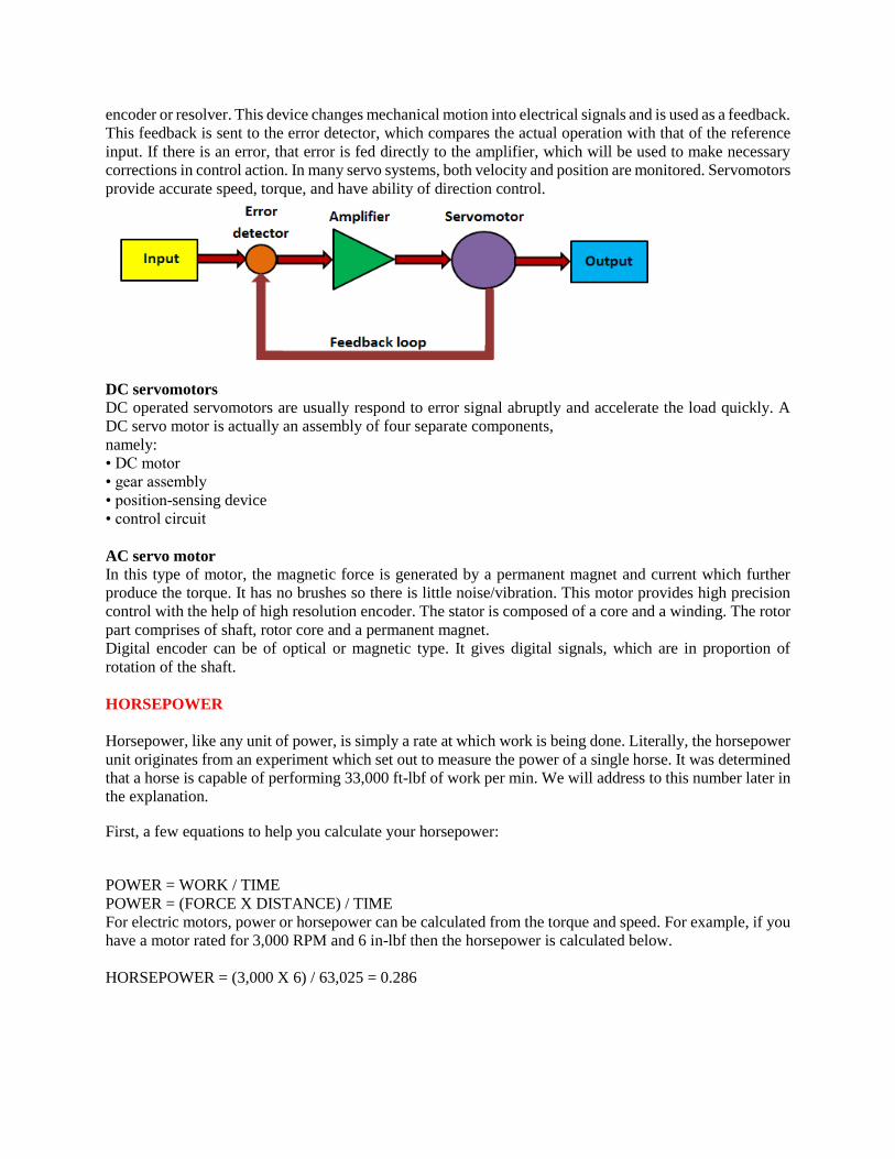
encoder or resolver. This device changes mechanical motion into electrical signals and is used as a feedback.
This feedback is sent to the error detector, which compares the actual operation with that of the reference
input. If there is an error, that error is fed directly to the amplifier, which will be used to make necessary
corrections in control action. In many servo systems, both velocity and position are monitored. Servomotors
provide accurate speed, torque, and have ability of direction control.
DC servomotors DC operated servomotors are usually respond to error signal abruptly and accelerate the load quickly. A
DC servo motor is actually an assembly of four separate components,
namely:
• DC motor
• gear assembly
• position-sensing device
• control circuit
AC servo motor In this type of motor, the magnetic force is generated by a permanent magnet and current which further
produce the torque. It has no brushes so there is little noise/vibration. This motor provides high precision
control with the help of high resolution encoder. The stator is composed of a core and a winding. The rotor
part comprises of shaft, rotor core and a permanent magnet.
Digital encoder can be of optical or magnetic type. It gives digital signals, which are in proportion of
rotation of the shaft.
HORSEPOWER
Horsepower, like any unit of power, is simply a rate at which work is being done. Literally, the horsepower
unit originates from an experiment which set out to measure the power of a single horse. It was determined
that a horse is capable of performing 33,000 ft-lbf of work per min. We will address to this number later in
the explanation.
First, a few equations to help you calculate your horsepower:
POWER = WORK / TIME
POWER = (FORCE X DISTANCE) / TIME
For electric motors, power or horsepower can be calculated from the torque and speed. For example, if you
have a motor rated for 3,000 RPM and 6 in-lbf then the horsepower is calculated below.
HORSEPOWER = (3,000 X 6) / 63,025 = 0.286
63,025 is a constant when using RPM for speed and in-lbf for torque units. 5,252 is another common
constant if the speed is in RPM and torque is in ft-lbf. If the units are different then simply make the unit
conversion.
The derivation of these constants is done using the 33,000 ft-lbf /min = 1 horsepower. Though horsepower
units are a derivative of the 33,000 ft-lbf/min, it is not critical to understanding how to calculate motor
horsepower for speed and torque.
Another common unit of power that motors are rated in is watts. The conversion from watts to horsepower
is 745.7 watts = 1 hp.
Calculate Speed, Torque and Power
Calculate Estimated Electrical Current and Losses for Optimum Motor Selection
Easily and Accurately Convert Units of Measurement
Customizable, Printed Report Function
Calculate Operating Costs
Path-Planning
Path-planning is an important primitive for autonomous mobile robots that lets robots find the shortest – or
otherwise optimal – path between two points. Otherwise optimal paths could be paths that minimize the
amount of turning, the amount of braking or whatever a specific application requires. Algorithms to find a
shortest path are important not only in robotics, but also in network routing, video games and gene
sequencing.
Path-planning requires a map of the environment and the robot to be aware of its location with respect to
the map. We will assume for now that the robot is able to localize itself, is equipped with a map, and capable
of avoiding temporary obstacles on its way.
In order to plan a path, we somehow need to represent the environment in the computer. We differentiate
between two complementary approaches: discrete and continuous approximations. In a discrete
approximation, a map is sub-divided into chunks of equal e.g., a grid or hexagonal map or differing sizes
e.g., rooms in a building. The latter maps are also known as topological maps. Discrete maps lend
themselves well to a graph representation. Here, every chunk of the map corresponds to a vertex also known
as “node” which are connected by edges, if a robot can navigate from one vertex to the other. For example
a road-map is a topological map, with intersections as vertices and roads as edges. Computationally, a graph
might be stored as an adjacency or incidence list/matrix. A continuous approximation requires the definition
of inner (obstacles) and outer boundaries, typically in the form of a polygon, whereas paths can be encoded
as sequences of real numbers. Discrete maps are the dominant representation in robotics.
Currently the most common map is the occupancy grid map. In a grid map, the environment is discretized
into squares of arbitrary resolution, e.g. 1cm x 1cm, on which obstacles are marked. In a probabilistic
occupancy grid, grid cells can also be marked with the probability that they contain an obstacle. This is
particularly important when the position of the robot that senses an obstacle is uncertain. Disadvantages of
grid maps are their large memory requirements as well as computational time to traverse data structures
with large numbers of vertices. A solution to the latter problem are topological maps that encode entire
rooms as vertices and use edges to indicate navigable connections between them. There is no silver bullet,
and each application might require a different solution that could be a combination of different map types.
COMMON IMAGING DEVICE USED FOR ROBOT VISION SYSTEMS
Black and white videocon camera, charge coupled devices, solid-state camera, charge injection devices.
SEGMENTATION
Segmentation is the method to group areas of an image having similar characteristics or features into distinct
entities representing part of the image.
THRESHOLDING
Thresholding is a binary conversion technique in which each pixel is converted into a binary value either
black or white.
FUNCTIONS OF MACHINE VISION SYSTEM
Sensing and digitizing image data Image Processing and analysis Application
SENSORS AND TRANSDUCER
Sensor is a transducer that is used to make a measurement of a physical variable of interest.
Transducer is a device that converts the one form of information into another form without changing the
information content.
BASIC CLASSIFICATIONS OF SENSORS
Tactile Sensors, Proximity Sensors, Range sensors, Voice sensors etc.,
TACTILE SENSOR
Tactile sensor is device that indicates the contact between themselves and some other solid objects.
REGION GROWING
Region growing is a collection of segmentation techniques in which pixels are grouped in regions called
grid elements based on attribute similarities.
FEATURE EXTRACTION
In vision applications distinguishing one object from another is accomplished by means of features that
uniquely characterize the object. A feature (area, diameter, perimeter) is a single parameter that permits
ease of comparison and identification.
VARIOUS TECHNIQUES IN IMAGE PROCESSING AND ANALYSIS
Image data reduction Segmentation Feature extraction Object recognition
APPLICATION EXAMPLE OF A PROXIMITY SENSOR
Ground proximity warning system for aviation safety Vibration measurements of rotating shafts in
machinery Sheet break sensing in paper machine.
Roller coasters
Conveyor systems
WORKING OF INDUCTIVE TYPE PROXIMITY SENSOR
Inductive proximity sensors operate under the electrical principle of inductance.
Inductance is the phenomenon where fluctuating current, which by definition has a magnetic component
induces an electromotive force (emf) is a target object.
To amplify a devices inductance effect, a sensor manufacturer twists wire into a tight coil and runs a current
through it.
FEEDBACK DEVICES USED IN ROBOTICS.
Position Sensors Velocity Sensors
TYPES OF ENCODERS
Incremental encoders Absolute encoders
FRAME GRABBER
It is a hardware device used to capture and store the digital image.
TYPES OF POSITION SENSORS
Incremental encoders Absolute encoders Resistive position sensors
Linear variable differential transformer. Encoders
Potentiometer Resolver.
TACTILE ARRAY SENSOR
Tactile array sensor is a special type of force senor composed of a matrix of force sensing elements.
Characteristics of Sensors.
Resolution:
It is the minimum step size within the range of measurement of a sensor.in a wire-wound potentiometer, it
will be equal to resistance of one turn of wire. In digital devices with ‗n‘ bits, resolution is ‗Full range/2n‘.
Sensitivity:
It is defined as the change in output response divided by the change in input response. Highly sensitive
sensors show larger fluctuations in output as a result of fluctuations in input.
Linearity:
It represents the relationship between input variations and output variations.
In a sensor with linear ouput, any change in input at any level within the range will produce the same change
in output.
Range:
It is the difference between the smallest and the largest outputs that a sensor can provide, or the difference
between the smallest and largest inputs with which it can operate properly.

Response time:
It is the time that a sensor‘s ouput requires to reach a certain percentage of total change.
It is also defined as the time required to observe the changein output as a result of change in input for
example, ordinary mercury thermometer responsetime and digital thermometer
response time.
Frequency response:
The frequency response is the range in which the system‘s ability to resonate to the input remains relatively
high.
The larger the range of frequency response, the better the ability of the system to respond to varying input.
Reliability:
It is the ratio between the number of times a system operates properly and the number of times it is tried.
For continuous satisfactory operation, it is necessary to choose reliable sensors that last long while
considering the cost as well as other requirements.
Accuracy:
It shows how close the output of the sensor is to the expected value.
For a given input, certain expected output value is related to how close the sensor‘s output value is to this
value.
Repeatability:
For the same input if the output response is different each time, then repeatability is poor. Also, a specific
range is desirable for operational performance as the performanve of robots depends on sensors.
Repeatability is a random phenomenon and hence there is no compensation.
Interfacing:
Direct interfacing of the sensor to the microcontroller/microprocessor is desirable while some add-on circuit
may be necessary in certain special sensors.
The type of the sensor output is equally important. An ADC is required for analogue output sensors for
example, potentiometer ouput to microcontroller.
Size, weight and volume:
Size is a critical consideration for joint displacement sensors.
When robots are used as dynamic machines, weight of the sensor is important. Volume or spaces also
critical to micro robots and mobile robots used for surveillance. Cost is important expecially when quantity
involved is large in the end application.
Encoders Synchros Resolvers Potentiometers
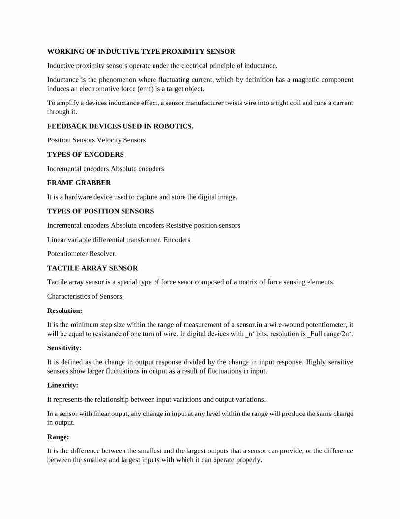
Types of Position Sensor:
Position sensors use different sensing principles to sense the displacement of a body. Depending upon the
different sensing principles used for position sensors, they can be classified as follows:
1. Resistance-based or Potentiometric Position sensors
2. Capacitive position sensors
3. Linear Voltage Differential Transformers
4. Magnetostrictive Linear Position Sensor
5. Eddy Current based position Sensor
6. Hall Effect based Magnetic Position Sensors
7. Fiber-Optic Position Sensor
8. Optical Position Sensors
Potentiometric Position Sensors:
Potentiometric position sensor use resistive effect as the sensing principle. The sensing element is simply a
resistive (or conductive) track. A wiper is attached to the body or part of the body whose displacement is
to be measured. The wiper is in contact with the track. As the wiper (with the body or its part) moves, the
resistance between one end of the track and the wiper changes. Thus, the resistance becomes a function of
the wiper position. The change in resistance per unit change in wiper position is linear.
Resistance, proportional to wiper position, is measured using voltage divider arrangement. A constant
voltage is applied across the ends of the track and the voltage across the resistance between the wiper and
one end of the track is measured. Thus, voltage output across the wiper and one end of the track is
proportional to the wiper position.
The conductive track can be made linear or angular depending upon the requirements. The tracks are made
from carbon , resistance wire or piezo resistive material.
Working principle of Range sensors with neat sketch.
The distance between the object and the robot hand is measured using the range sensors Within it is range
of operation. The calculation of the distance is by visual processing. Range sensors find use in robot
navigation and avoidance of the obstacles in the path. The - location and the general shape characteristics
of the part in the work envelope of the robot S done by special applications for the range sensors. There are
several approaches like, triangulation method, structured lighting approach and time-of flight range finders
etc. In these cases the source of illumination can be light- source, laser beam or based on ultrasonic.
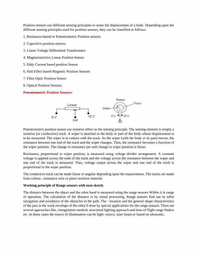
Triangulation Method:
This is the simplest of the techniques, which is easily demonstrated in the Figure. The object is swept over
by a narrow beam of sharp light. The sensor focussed on a small spot of the object surface detects the
reflected beam of light. If ‗a‘ is the angle made by the illuminating source and ‗b‘is the distance between
source and the sensor, the distance ‗c of the sensor on the robot is given as
WORKING PRINCIPLE OF PROXIMITY SENSORS
Proximity Sensors:
The output of the proximity sensors gives an indication of the presence of an object with in the vicinity job
operation. In robotics these sensors are used to generate information of object grasping and obstacle
avoidance. This section deals with some of the important proximity sensors used in robotics.
The ferromagnetic material brought close to this type of sensor results in change in position of the flux lines
of the permanent magnet leading to change in inductance of the coil. The induced current pulse in the coil
with change in amplitude and shape is proportional to rate of change of flux line in magnet.

Inductive Proximity Sensors:
Construction:
The proximity inductive sensor basically consists of a wound coil located in front of a permanent magnet
encased inside a rugged housing. The lead from the coil, embedded in resin is connected to the display
through a connector.
The effect of bringing the sensor in close proximity to a ferromagnetic material causes a change in the
position of the flux lines of the permanent magnet.
Machine vision systems of Robot
Machine vision system consists of: Lighting, camera, A/D convertor, frame grabber, computer processor,
robot controller and robot manipulator.

The hardware and software for performing the function of sensing and processing the image and utilising
the results obtained to command the robot.
The sensing and digitizing functions involve the input of vision data by means of a camera focused on the
scene of interest. Special lighting techniques are frequently used to obtain an image of sufficient contrast
for later processing.
The image viewed by the camera is typically digitized and stored in computer memory. The digital image
is called a frame of vision data, and is frequently captured by a hardware device called a frame grabber.
These devices are capable of digitizing images at the rate of 30 frames per second. The frames consist of a
matrix of data representing projections of the scene sensed by the camera.
The elements of the matrix are called picture elements, or pixels. The number of pixels are determined by
a sampling process per formed on each image frame.
A single pixel is the projection of a small portion of the scene which reduces that portion to a single value.
The value is a measure of the light intensity for that element of the scene.
Each pixel intensity is converted into a digital value. (We are ignoring the additional complexities involved
in the operation of a color video camera.)
The digitized image matrix for each frame is stored and then subjected to image processing and analysis
functions for data reduction and interpretation of the image.
These steps are required in order to permit the real-time application of vision analysis required in robotic
applications.
Typically an image frame will be thresholded to produce a binary image, and then various feature
measurements will further reduce the data representation of the image.
This data reduction can change the representation of a frame from several.
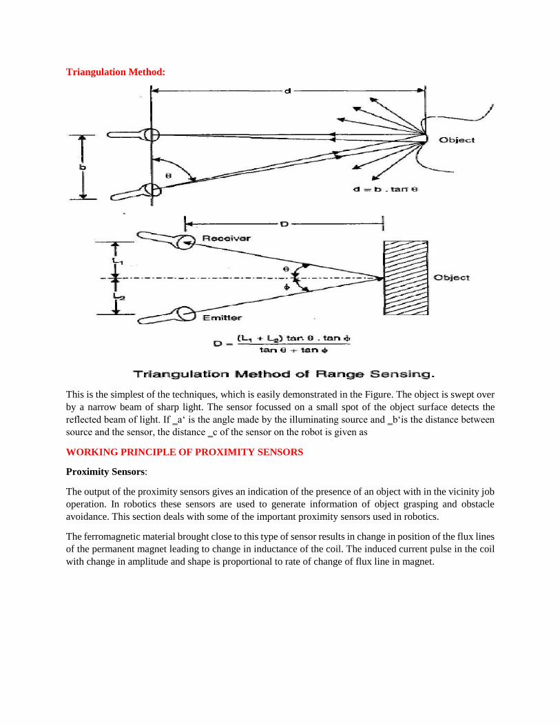
Optical encoders:
The absolute optical encoder employs the same basic construction as incremental optical encoders except
that there are more tracks of stripes and a corresponding number of receivers and transmitters. Usually, the
stripes are arranged to provide a binary number proportional to the shaft angle. The first track might have
two stripes, the second four, the third eight, and so on. In this way the angle can be read directly from the
encoder without any necessary counting. Figure illustrates an absolute optical encoder.
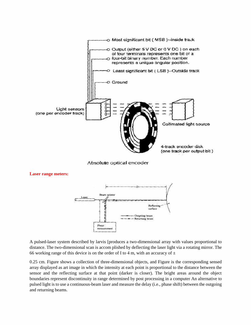
Laser range meters:
A pulsed-laser system described by larvis [produces a two-dimensional array with values proportional to
distance. The two-dimensional scan is accom plished by deflecting the laser light via a rotating mirror. The
66 working range of this device is on the order of I to 4 m, with an accuracy of ±
0.25 cm. Figure shows a collection of three-dimensional objects, and Figure is the corresponding sensed
array displayed as art image in which the intensity at each point is proportional to the distance between the
sensor and the reflecting surface at that point (darker is closer). The bright areas around the object
boundaries represent discontinuity in range determined by post processing in a computer An alternative to
pulsed light is to use a continuous-beam laser and measure the delay (i.e., phase shift) between the outgoing
and returning beams.

Capacitive type touch sensors:
Unlike inductive and Hall-effect sensors which detect only ferromagnetic materials, capacitive sensors are
potentially capable (with various degrees of sensitivity) of detecting all solid and liquid materials. As their
name implies, these sensors are based on detecting a change in capacitance induced by a surface that is
brought near the sensing element.
The basic components of a capacitive sensor are shown in Figure. The sensing element is a capacitor
composed of a sensitive electrode and a reference electrode. These can be, for example, a metallic disk and
ring separated by a dielectric material. A cavity of dry air is usually placed behind the capacitive element
to provide isolation. The rest of the sensor consists of electronic circuitry which can be included as an
integral part of the unit, in which case it is normally embedded in a resin to provide sealing and mechanical
support.
There are a number of electronic approaches for detecting proximity based on a change in capacitance. One
of the simplest includes the capacitor as part of an Oscillator circuit designed so that the oscillation starts
only when the capacitance of the sensor exceeds a predefined threshold value. The start of oscillation is
then translated into an output voltage which indicates the presence of an object. This method provides a
binary output whose triggering sensitivity depends on the threshold value.
A more complicated approach utilizes the capacitive element as part of a circuit which is continuously
driven by a reference sinusoidal waveform. A change in capacitance produces a phase shift between the
reference signal and a signal derived from the capacitive element. The phase shift is proportional to the
change in capacitance and can thus be used as a basic mechanism for proximity detection.
UNIT-III
Pre-requisite:
To study the basic mechanical movement and grippers.
OUTCOMES:
Analyze the function manipulator dynamics and force control.
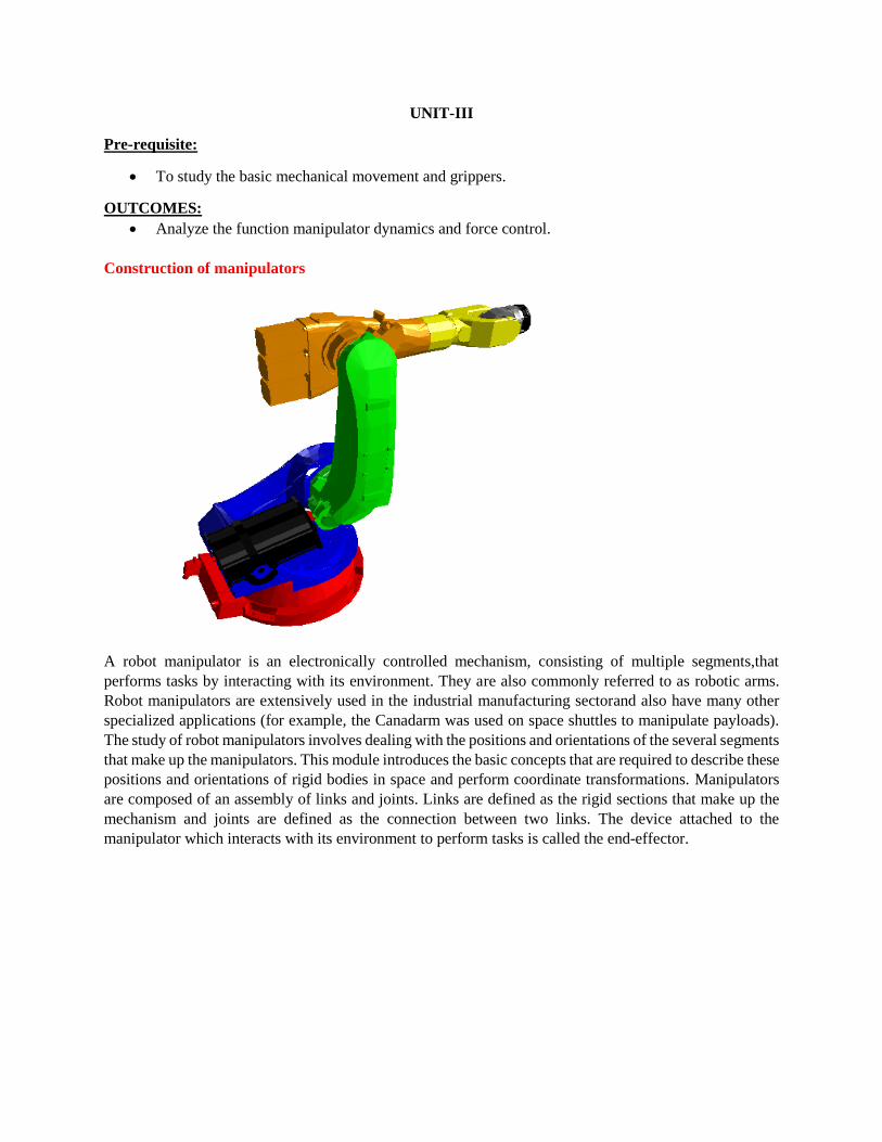
Construction of manipulators
A robot manipulator is an electronically controlled mechanism, consisting of multiple segments,that
performs tasks by interacting with its environment. They are also commonly referred to as robotic arms.
Robot manipulators are extensively used in the industrial manufacturing sectorand also have many other
specialized applications (for example, the Canadarm was used on space shuttles to manipulate payloads).
The study of robot manipulators involves dealing with the positions and orientations of the several segments
that make up the manipulators. This module introduces the basic concepts that are required to describe these
positions and orientations of rigid bodies in space and perform coordinate transformations. Manipulators
are composed of an assembly of links and joints. Links are defined as the rigid sections that make up the
mechanism and joints are defined as the connection between two links. The device attached to the
manipulator which interacts with its environment to perform tasks is called the end-effector.
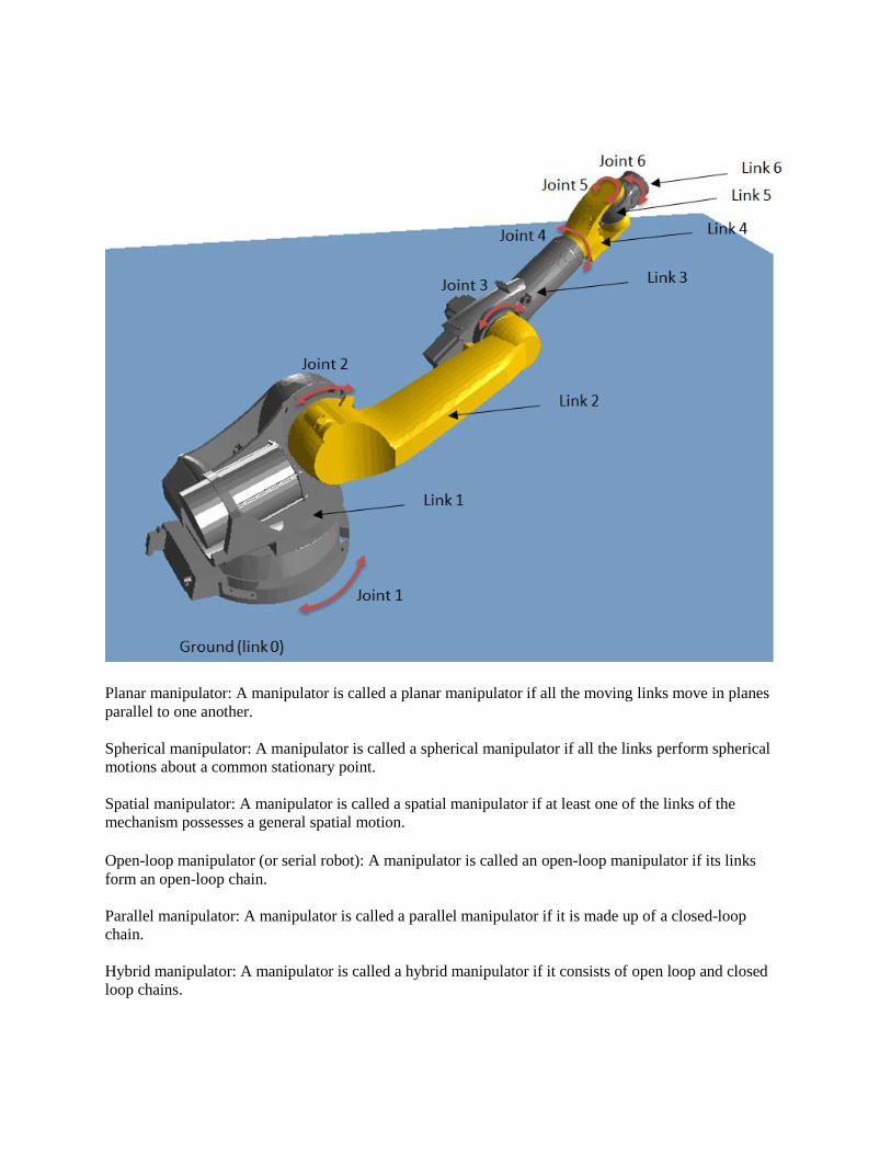
Planar manipulator: A manipulator is called a planar manipulator if all the moving links move in planes
parallel to one another.
Spherical manipulator: A manipulator is called a spherical manipulator if all the links perform spherical
motions about a common stationary point.
Spatial manipulator: A manipulator is called a spatial manipulator if at least one of the links of the
mechanism possesses a general spatial motion.
Open-loop manipulator (or serial robot): A manipulator is called an open-loop manipulator if its links
form an open-loop chain.
Parallel manipulator: A manipulator is called a parallel manipulator if it is made up of a closed-loop
chain.
Hybrid manipulator: A manipulator is called a hybrid manipulator if it consists of open loop and closed
loop chains.

Pneumatic actuators system with neat sketch.
Pneumatic systems use pressurized air to make things move. Basic pneumatic system consists of an air
generating unit and an air-consuming unit. Air compressed in compressor is not ready for use as such, air
has to be filtered, moisture present in air has to be dried, and for different applications in plant pressure of
air has to be varied. Several other treatments are given to the air before it reaches finally to the Actuators.
The figure gives an overview of a pneumatic system. Practically some accessories are added for economical
and efficient operation of system.
Compressor:
A device, which converts mechanical force and motion into pneumatic fluid power, is called
compressor. Every compressed-air system begins with a compressor, as it is the source of airflow for all
the downstream equipment and processes Electric Motor Electric motor is used to drive the compressor.
Air Receiver:
It is a container in which air is stored under pressure. Pressure Switch. Pressure Switch is used to maintain
the required pressure in the receiver; it adjusts the High Pressure Limit and Low Pressure Limit in the
receiver. The compressor is automatically turned off when the pressure is about to exceed the high limit
and it is also automatically turned on when the pressure is about to fall below the low limit.
Safety Valve:
The function of the safety valve is to release extra pressure if the pressure inside the receiver tends to exceed
the safe pressure limit of the receiver.
Check Valve:
The valve enables flow in one direction and blocks flow in a counter direction is called Check Valve. Once
compressed air enters the receiver via check valve, it is not allowed to go back even when the compressor
is stopped.
Direction Control Valve:
Directional-control valve are devices used to change the flow direction of fluid within a
Pneumatic/Hydraulic circuit. They control compressed-air flow to cylinders, rotary actuators, grippers, and
other mechanisms in packaging, handling, assembly, and countless other applications. These valves can be
actuated either manually or electrically.
Pneumatic Actuator:
A device in which power is transferred from one pressurized medium to another without intensification.
Pneumatic actuators are normally used to control processes requiring quick and accurate response, as they
do not require a large amount of motive force. They may be reciprocating cylinders, rotating motors or may
be a robot end effectors.

Electronic And Pneumatic Manipulator Control Circuits
Actuators are output devices which convert energy from pressurized hydraulic oil or compressed air into
the required type of action or motion. In general, hydraulic or pneumatic systems are used for gripping
and/or moving operations in industry. These operations are carried out by using actuators.
Actuators can be classified into three types.
1. Linear actuators: These devices convert hydraulic/pneumatic energy into linear motion.
2. Rotary actuators: These devices convert hydraulic/pneumatic energy into rotary motion.
3. Actuators to operate flow control valves: these are used to control the flow and pressure of fluids such
as gases, steam or liquid.
The construction of hydraulic and pneumatic linear actuators is similar. However they differ at their
operating pressure ranges. Typical pressure of hydraulic cylinders is about 100 bar and of pneumatic
system is around 10 bar.
1. Single acting cylinder
These cylinders produce work in one direction of motion hence they are named as single acting cylinders.
The compressed air pushes the piston located in the cylindrical barrel causing the desired motion. The
return stroke takes place by the action of a spring. Generally the spring is provided on the rod side of the
cylinder.
2. Double acting cylinder

The main parts of a hydraulic double acting cylinder are: piston, piston rod, cylinder tube, and end caps.
The piston rod is connected to piston head and the other end extends out of the cylinder. The piston divides
the cylinder into two chambers namely the rod end side and piston end side. The seals prevent the leakage
of oil between these two chambers. The cylindrical tube is fitted with end caps. The pressurized oil, air
enters the cylinder chamber through the ports provided. In the rod end cover plate, a wiper seal is provided
to prevent the leakage of oil and entry of the contaminants into the cylinder. The combination of wiper seal,
bearing and sealing ring is called as cartridge assembly. The end caps may be attached to the tube by
threaded connection, welded connection or tie rod connection. The piston seal prevents metal to metal
contact and wear of piston head and the tube. These seals are replaceable. End cushioning is also provided
to prevent the impact with end caps.
3. Cylinder end cushions
Double acting cylinders generally contain cylinder cushions at the end of the cylinder to slow down the
movement of the piston near the end of the stroke. Cushioning arrangement avoids the damage due to the
impact occurred when a fast moving piston is stopped by the end caps. Deceleration of the piston starts
when the tapered plunger enters the opening in the cap and closes the main fluid exit. This restricts the
exhaust flow from the barrel to the port. This throttling causes the initial speed reduction. During the last
portion of the stroke the oil has to exhaust through an adjustable opening since main fluid exit closes.
Thus the remaining fluid exists through the cushioning valve. Amount of cushioning can be adjusted by
means of cushion screw. A check valve is provided to achieve fast break away from the end position
during retraction motion. A bleed screw is built into the check valve to remove the air bubbles present in a
hydraulic type system.
4. Gear motor: a rotary actuator Rotary actuators convert energy of pressurized fluid into rotary motion. Rotary actuators are similar to
electric motors but are run on hydraulic or pneumatic power.
It consists of two inter meshing gears inside a housing with one gear attached to the drive shaft. The air
enters from the inlet, causes the rotation of the meshing gear due to difference in the pressure and
produces the torque. The air exists from the exhaust port. Gear motors tend to leak at low speed, hence are
generally used for medium speed applications.
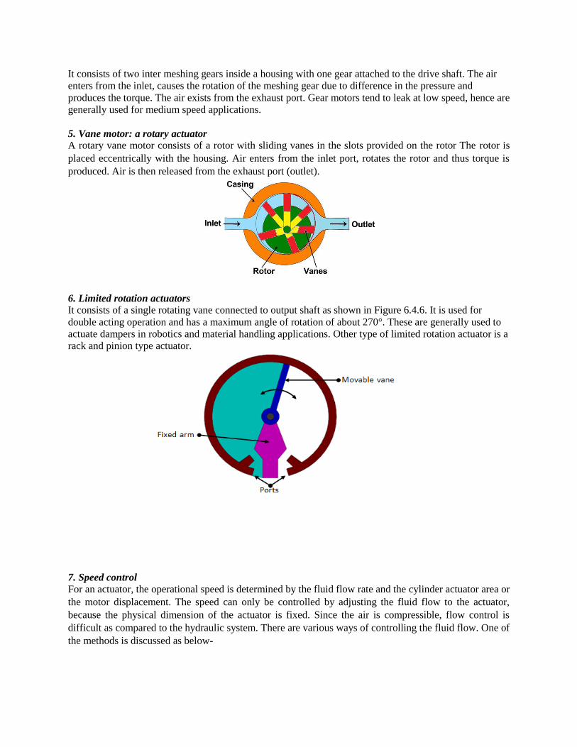
5. Vane motor: a rotary actuator A rotary vane motor consists of a rotor with sliding vanes in the slots provided on the rotor The rotor is
placed eccentrically with the housing. Air enters from the inlet port, rotates the rotor and thus torque is
produced. Air is then released from the exhaust port (outlet).
6. Limited rotation actuators It consists of a single rotating vane connected to output shaft as shown in Figure 6.4.6. It is used for
double acting operation and has a maximum angle of rotation of about 270°. These are generally used to
actuate dampers in robotics and material handling applications. Other type of limited rotation actuator is a
rack and pinion type actuator.
7. Speed control For an actuator, the operational speed is determined by the fluid flow rate and the cylinder actuator area or
the motor displacement. The speed can only be controlled by adjusting the fluid flow to the actuator,
because the physical dimension of the actuator is fixed. Since the air is compressible, flow control is
difficult as compared to the hydraulic system. There are various ways of controlling the fluid flow. One of
the methods is discussed as below-
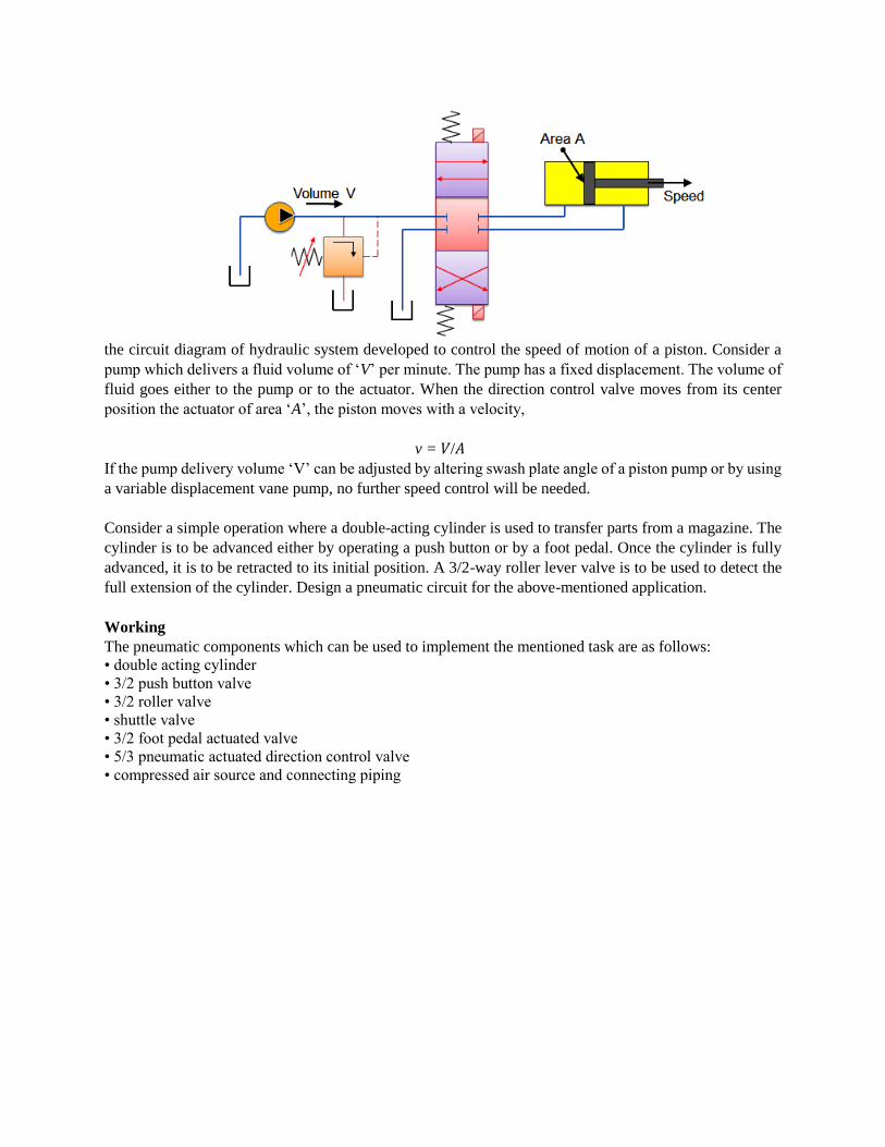
the circuit diagram of hydraulic system developed to control the speed of motion of a piston. Consider a
pump which delivers a fluid volume of ‘V’ per minute. The pump has a fixed displacement. The volume of
fluid goes either to the pump or to the actuator. When the direction control valve moves from its center
position the actuator of area ‘A’, the piston moves with a velocity,
v = 𝑉/𝐴
If the pump delivery volume ‘V’ can be adjusted by altering swash plate angle of a piston pump or by using
a variable displacement vane pump, no further speed control will be needed.
Consider a simple operation where a double-acting cylinder is used to transfer parts from a magazine. The
cylinder is to be advanced either by operating a push button or by a foot pedal. Once the cylinder is fully
advanced, it is to be retracted to its initial position. A 3/2-way roller lever valve is to be used to detect the
full extension of the cylinder. Design a pneumatic circuit for the above-mentioned application.
Working
The pneumatic components which can be used to implement the mentioned task are as follows:
• double acting cylinder
• 3/2 push button valve
• 3/2 roller valve
• shuttle valve
• 3/2 foot pedal actuated valve
• 5/3 pneumatic actuated direction control valve
• compressed air source and connecting piping
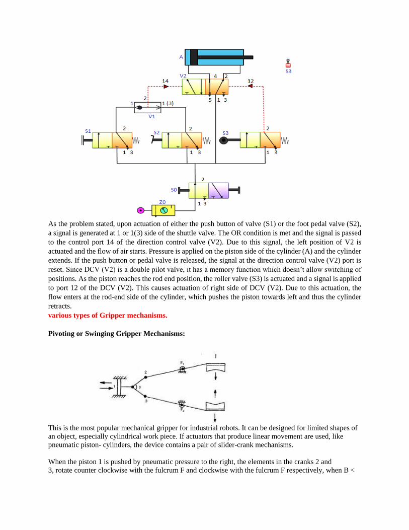
As the problem stated, upon actuation of either the push button of valve (S1) or the foot pedal valve (S2),
a signal is generated at 1 or 1(3) side of the shuttle valve. The OR condition is met and the signal is passed
to the control port 14 of the direction control valve (V2). Due to this signal, the left position of V2 is
actuated and the flow of air starts. Pressure is applied on the piston side of the cylinder (A) and the cylinder
extends. If the push button or pedal valve is released, the signal at the direction control valve (V2) port is
reset. Since DCV (V2) is a double pilot valve, it has a memory function which doesn’t allow switching of
positions. As the piston reaches the rod end position, the roller valve (S3) is actuated and a signal is applied
to port 12 of the DCV (V2). This causes actuation of right side of DCV (V2). Due to this actuation, the
flow enters at the rod-end side of the cylinder, which pushes the piston towards left and thus the cylinder
retracts.
various types of Gripper mechanisms.
Pivoting or Swinging Gripper Mechanisms:
This is the most popular mechanical gripper for industrial robots. It can be designed for limited shapes of
an object, especially cylindrical work piece. If actuators that produce linear movement are used, like
pneumatic piston- cylinders, the device contains a pair of slider-crank mechanisms.
When the piston 1 is pushed by pneumatic pressure to the right, the elements in the cranks 2 and
3, rotate counter clockwise with the fulcrum F and clockwise with the fulcrum F respectively, when B <
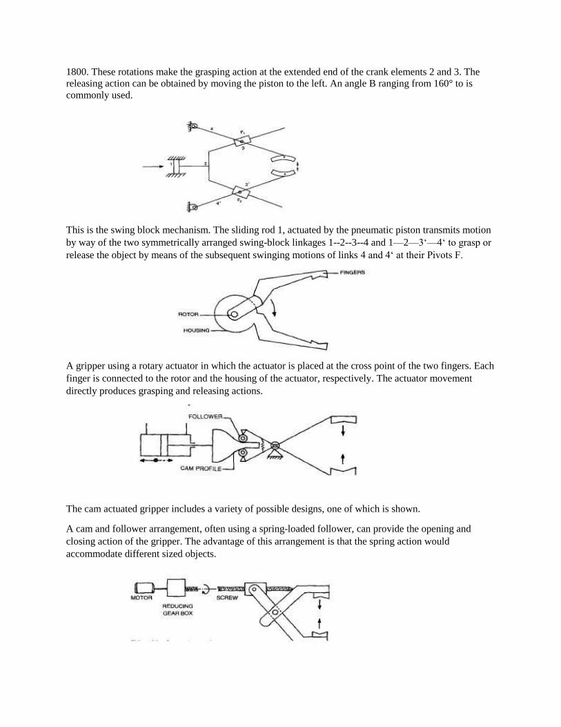
1800. These rotations make the grasping action at the extended end of the crank elements 2 and 3. The
releasing action can be obtained by moving the piston to the left. An angle B ranging from 160° to is
commonly used.
This is the swing block mechanism. The sliding rod 1, actuated by the pneumatic piston transmits motion
by way of the two symmetrically arranged swing-block linkages 1--2--3--4 and 1—2—3‘—4‘ to grasp or
release the object by means of the subsequent swinging motions of links 4 and 4‘ at their Pivots F.
A gripper using a rotary actuator in which the actuator is placed at the cross point of the two fingers. Each
finger is connected to the rotor and the housing of the actuator, respectively. The actuator movement
directly produces grasping and releasing actions.
The cam actuated gripper includes a variety of possible designs, one of which is shown.
A cam and follower arrangement, often using a spring-loaded follower, can provide the opening and
closing action of the gripper. The advantage of this arrangement is that the spring action would
accommodate different sized objects.

The screw is turned by a motor, usually accompanied by a speed reduction mechanism. Due to the
rotation of the screw, the threaded block moves, causing the opening and dosing of the fingers depending
on the direction of rotation of the screw.
Magnetic Grippers.
Magnetic grippers are used extensively on ferrous materials.
In general, magnetic grippers offer the following advantages in robotic handling operations
Variations in part size can be tolerated
Pickup times are very fast
They have ability to handle metal parts with holes
Only one surface is required for gripping
The residual magnetism remaining in the work piece may cause problems. Mother potential disadvantage
is the problem of picking up one sheet at a time from a stack. The magnetic attraction
tends to penetrate beyond the top sheet in the stack, resulting in the possibility that more than a
single sheet will be lifted by the magnet.
Magnetic grippers can use either electromagnets or permanent magnets. Electromagnetic grippers are
easier to control, but require a source of dc power and an appropriate controller. When the part is to be
released, the control unit reverses the polarity at a reduced power level before switching off the
electromagnet.
Permanent magnets do not require an external power and hence they can be used in hazardous and
explosive environments, because there is no danger of sparks which might cause ignition in such
environments. When the part is to be released at the end of the handling cycle, in case of permanent
magnet grippers, some means of separating the part from the magnet must be provided
UNIT-IV
Pre-requisite:
To study the basic knowledge of kinematics of mechanisms.
To study the Euler, Lagrangian formulation of Robot dynamics.
To study the basic components and layout of linkages in the assembly of mechanisms.
OUTCOMES:
To learn the concept of direct kinematics and inverse kinematics.
To develop attitude to analyze various mechanisms.
FORWARD KINEMATICS
A manipulator is composed of serial links which are affixed to each other revolute or prismatic
joints from the base frame through the end-effector. Calculating the position and orientation of the
end-effector in terms of the joint variables is called as forward kinematics. In order to have forward
kinematics for a robot mechanism in a systematic manner, one should use a suitable kinematics
model. Denavit-Hartenberg method that uses four parameters is the most common method for
describing the robot kinematics. These parameters ai-1, α −1i , di and θi are the link length, link
twist, link offset and joint angle, respectively. A coordinate frame is attached to each joint to
determine DH parameters. Zi axis of the coordinate frame is pointing along the rotary or sliding
direction general manipulator.
REVERSE KINEMATICS
The inverse kinematics problem of the serial manipulators has been studied for many decades. It
is needed in the control of manipulators. Solving the inverse kinematics is computationally
expansive and generally takes a very long time in the real time control of manipulators. Tasks to
be performed by a manipulator are in the Cartesian space, whereas actuators work in joint space.
Cartesian space includes orientation matrix and position vector. However, joint space is
represented by joint angles. The conversion of the position and orientation of a manipulator end-
effector from Cartesian space to joint space is called as inverse kinematics problem. There are
two solutions approaches namely, geometric and algebraic used for deriving the inverse
kinematics solution, analytically.
Kinematics is Geometry of Motion. It is one of the most fundamental disciplines in robotics,
providing tools for describing the structure and behavior of robot mechanisms. In this chapter, we
will discuss how the motion of a robot mechanism is described, how it responds to actuator
movements, and how the individual actuators should be coordinated to obtain desired motion at
the robot end-effecter. These are questions central to the design and control of robot mechanisms.
To begin with, we will restrict ourselves to a class of robot mechanisms that work within a plane,
i.e. Planar Kinematics. Planar kinematics is much more tractable mathematically, compared to
general three-dimensional kinematics.
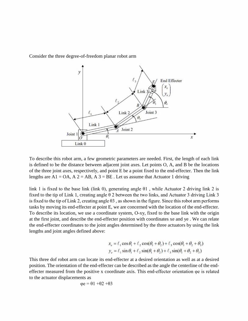
Consider the three degree-of-freedom planar robot arm
To describe this robot arm, a few geometric parameters are needed. First, the length of each link
is defined to be the distance between adjacent joint axes. Let points O, A, and B be the locations
of the three joint axes, respectively, and point E be a point fixed to the end-effecter. Then the link
lengths are A1 = OA, A 2 = AB, A 3 = BE . Let us assume that Actuator 1 driving
link 1 is fixed to the base link (link 0), generating angle θ1 , while Actuator 2 driving link 2 is
fixed to the tip of Link 1, creating angle θ 2 between the two links, and Actuator 3 driving Link 3
is fixed to the tip of Link 2, creating angle θ3 , as shown in the figure. Since this robot arm performs
tasks by moving its end-effecter at point E, we are concerned with the location of the end-effecter.
To describe its location, we use a coordinate system, O-xy, fixed to the base link with the origin
at the first joint, and describe the end-effecter position with coordinates xe and ye . We can relate
the end-effecter coordinates to the joint angles determined by the three actuators by using the link
lengths and joint angles defined above:
This three dof robot arm can locate its end-effecter at a desired orientation as well as at a desired
position. The orientation of the end-effecter can be described as the angle the centerline of the end-
effecter measured from the positive x coordinate axis. This end-effecter orientation φe is related
to the actuator displacements as
φe = θ1 +θ2 +θ3

The above three equations describe the position and orientation of the robot end-effecter viewed
from the fixed coordinate system in relation to the actuator displacements. In general, a set of
algebraic equations relating the position and orientation of a robot end-effecter, or any significant
part of the robot, to actuator or active joint displacements, is called Kinematic Equations, or more
specifically, Forward Kinematic Equations in the robotics literature.
Inverse Kinematics of Planar Mechanisms
The vector kinematic equation derived in the previous section provides the functional relationship between
the joint displacements and the resultant end-effecter position and orientation. By substituting values of
joint displacements into the right-hand side of the kinematic equation, one can immediately find the
corresponding end-effecter position and orientation. The problem of finding the end-effecter position and
orientation for a given set of joint displacements is referred to as the direct kinematics problem. This is
simply to evaluate the right-hand side of the kinematic equation for known joint displacements. In this
section, we discuss the problem of moving the end-effecter of a manipulator arm to a specified position and
orientation. We need to find the joint displacements that lead the end-effecter to the specified position and
orientation. This is the inverse of the previous problem, and is thus referred to as the inverse kinematics
problem. The kinematic equation must be solved for joint displacements, given the end-effecter
position and orientation. Once the kinematic equation is solved, the desired end-effecter motion
can be achieved by moving each joint to the determined value. In the direct kinematics problem,
the end-effecter location is determined uniquely for any given set of joint displacements. On the
other hand, the inverse kinematics is more complex in the sense that multiple solutions may exist
for the same end-effecter location. Also, solutions may not always exist for a particular range of
end-effecter locations and arm structures. Furthermore, since the kinematic equation is comprised
of nonlinear simultaneous equations with many trigonometric functions, it is not always possible
to derive a closed-form solution, which is the explicit inverse function of the kinematic equation.
When the kinematic equation cannot be solved analytically, numerical methods are used in order
to derive the desired joint displacement
Consider the three dof planar arm The problem is to find three joint angles θ1 ,θ2 ,θ3 that lead the
end effecter to a desired position and orientation, xe , ye ,φe . We take a two-step approach. First,
we find the position of the wrist, point B, from xe , ye ,φe . Then we find θ1 ,θ2 from the wrist
position. Angle θ3 can be determined immediately from the wrist position.
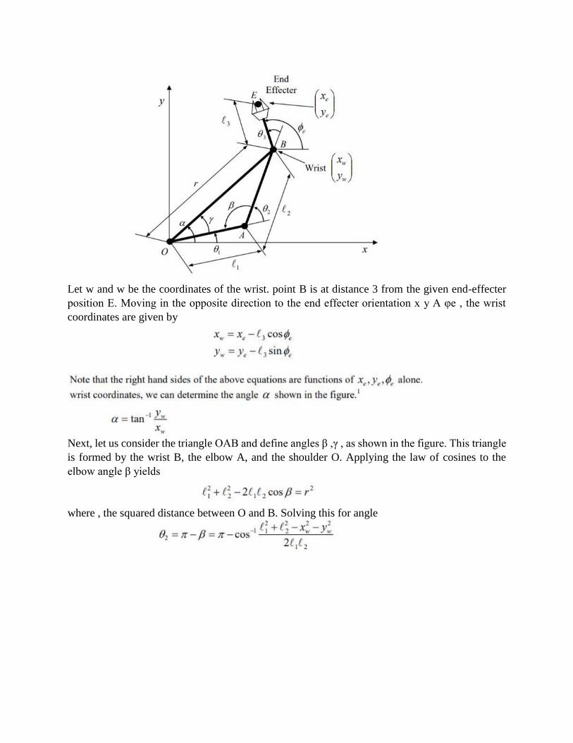
Let w and w be the coordinates of the wrist. point B is at distance 3 from the given end-effecter
position E. Moving in the opposite direction to the end effecter orientation x y A φe , the wrist
coordinates are given by
Next, let us consider the triangle OAB and define angles β ,γ , as shown in the figure. This triangle
is formed by the wrist B, the elbow A, and the shoulder O. Applying the law of cosines to the
elbow angle β yields
where , the squared distance between O and B. Solving this for angle
Inverse kinematics problems often possess multiple solutions, like the above example, since they
are nonlinear. Specifying end-effecter position and orientation does not uniquely determine the
whole configuration of the system. This implies that vector p, the collective position and
orientation of the end-effecter, cannot be used as generalized coordinates.
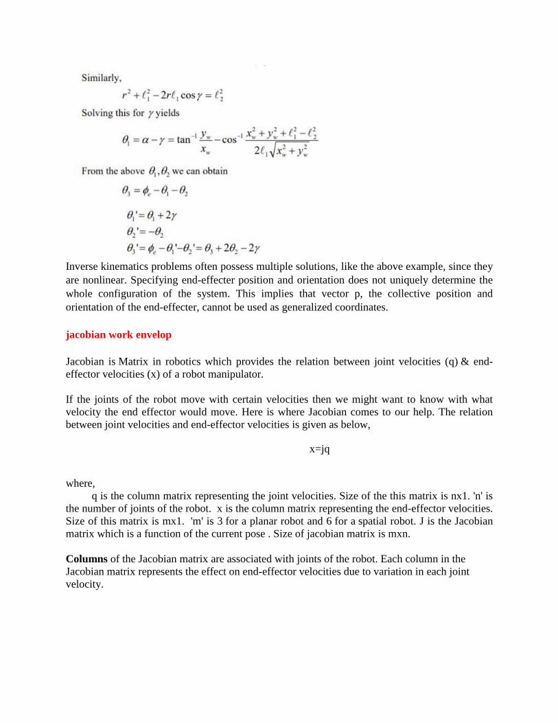
jacobian work envelop
Jacobian is Matrix in robotics which provides the relation between joint velocities (q) & end-
effector velocities (x) of a robot manipulator.
If the joints of the robot move with certain velocities then we might want to know with what
velocity the end effector would move. Here is where Jacobian comes to our help. The relation
between joint velocities and end-effector velocities is given as below,
x=jq
where,
q is the column matrix representing the joint velocities. Size of the this matrix is nx1. 'n' is
the number of joints of the robot. x is the column matrix representing the end-effector velocities.
Size of this matrix is mx1. 'm' is 3 for a planar robot and 6 for a spatial robot. J is the Jacobian
matrix which is a function of the current pose . Size of jacobian matrix is mxn.
Columns of the Jacobian matrix are associated with joints of the robot. Each column in the
Jacobian matrix represents the effect on end-effector velocities due to variation in each joint
velocity.
Which means, the first column represents the effect of joint1 velocity (q1) on end-effector
velocities (x), second column is associated with joint2 velocity (q2) and similarly nth column is
effect of nth joint velocity (qn ) on end-effector velocities .
Hence the number of columns in the Jacobian matrix is equal to the number of joints in the
manipulator.
If we closely observe the x matrix, it has two parts.The first three elements of the end-effector
velocity matrix X are linear velocities [rate of change of position] and the last three elements are
the angular velocites [rate of change of orientation] in (x,y,z) direction respectively.
Similarly, rows of the Jacobian matrix can also be split into two part. The first three rows are
associated with linear velocities of end-effector and the last three rows are associated with
the angular velocities of end-effector due to change in velocities of all the joints combined.
Hence we can call the upper part of the Jacobian matrix as Linear velocity Jacobian ( jv ) and the
lower part as Angular velocity Jacobian ( jw ).
Methods to derive Jv and Jw are different. We will find them separately and later combine to get
our final Jacobian matrix.
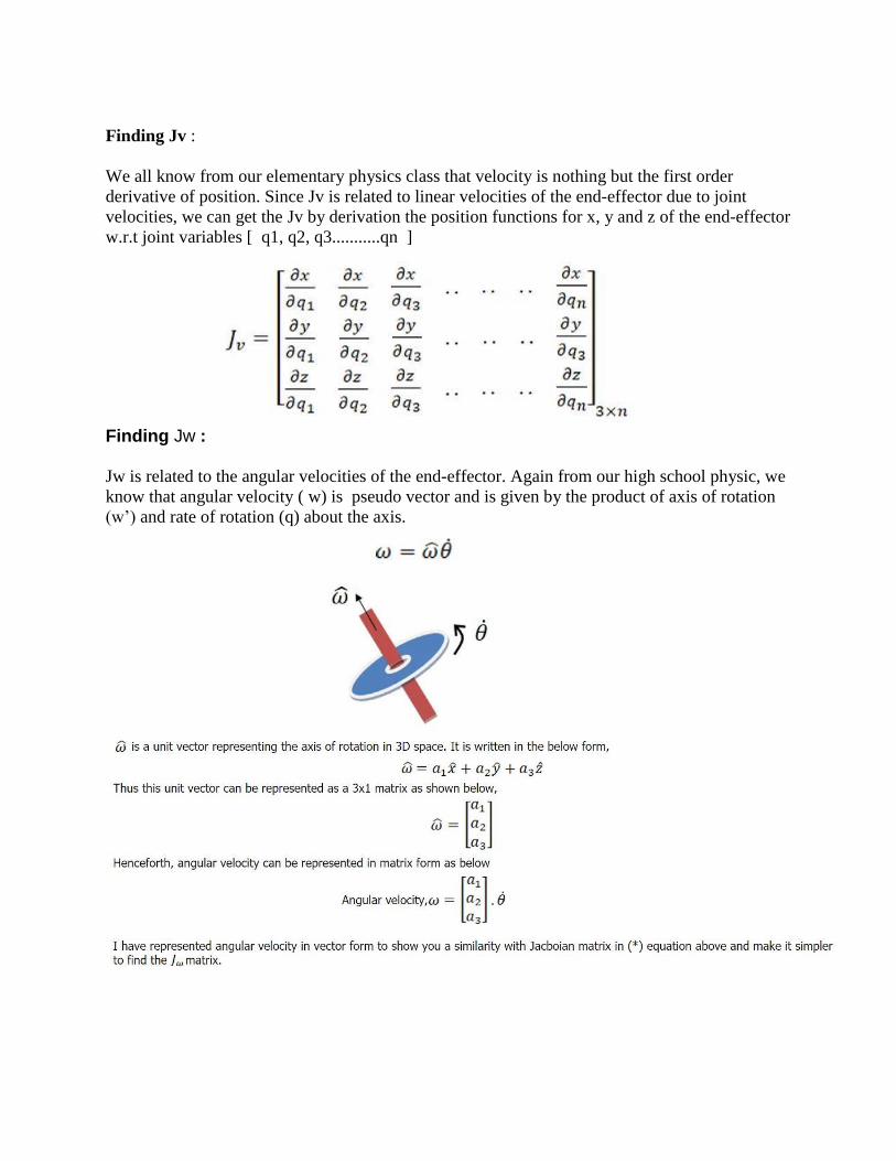
Finding Jv :
We all know from our elementary physics class that velocity is nothing but the first order
derivative of position. Since Jv is related to linear velocities of the end-effector due to joint
velocities, we can get the Jv by derivation the position functions for x, y and z of the end-effector
w.r.t joint variables [ q1, q2, q3...........qn ]
Finding Jw : Jw is related to the angular velocities of the end-effector. Again from our high school physic, we
know that angular velocity ( w) is pseudo vector and is given by the product of axis of rotation
(w’) and rate of rotation (q) about the axis.
If we observe (*) equation, rate of rotation of all joints (joint velocities q1,q2,q3,....qn ) are
already present in the [ x ] matrix. So the only missing component to find the angular velocities of
the end-effector is the axis of rotation information of each joint. This information, i.e., joint axes
of all joints, is what jw matrix is all about.
robot programming languages
There are three basic methods for programming industrial robots but currently over 90%
are programmed using the teach method.
Teach Method
The logic for the program can be generated either using a menu based system or simply using a
text editor but the main characteristic of this method is the means by which the robot is taught the
positional data. A teach pendant with controls to drive the robot in a number of different co-
ordinate systems is used to manually drive the robot to the desired locations. These locations are
then stored with names that can be used within the robot program.
The co-ordinate systems available on a standard jointed arm robot are :-
JointCo-ordinates
The robot joints are driven independently in either direction.
GlobalCo-ordinates
The tool centre point of the robot can be driven along the X, Y or Z axes of the robots
global axis system. Rotations of the tool around these axes can also be performed
ToolCo-ordinates
Similar to the global co-ordinate system but the axes of this one are attached to the tool
WorkpieceCo-ordinates
With many robots it is possible to set up a co-ordinate system at any point within the working
area. These can be especially useful where small adjustments to the program are required as it is
easier to make them along a major axis of the co-ordinate system than along a general line. The
effect of this is similar to moving the position and orientation of the global coordinate system.
This method of programming is very simple to use where simple movements are required. It does
have the disadvantage that the robot can be out of production for a long time during
reprogramming. While this is not a problem where robots do the same task for their entire life,
this is becoming less common and some robotic welding systems are performing tasks only a
few times before being reprogrammed.
Lead Through
This system of programming was initially popular but has now almost disappeared. It is
still however used by many paint spraying robots. The robot is programmed by being physically
moved through the task by an operator. This is exceedingly difficult where large robots are being
used and sometimes a smaller version of the robot is used for this purpose. Any hesitations or
inaccuracies that are introduced into the program cannot be edited out easily without

reprogramming the whole task. The robot controller simply records the joint positions at a fixed
time interval and then plays this back.
Programming Languages for Robotics
This article is all about giving an introduction about some of the programming languages
which are used to design Robots.
There are many programming languages which we use while building Robots, we have a
few programming languages which we always prefer to use in designing. Actually the
programming languages which we use mainly depend on the hardware one is using in building
robots.
Some of them are- URBI, C and BASIC. URBI is an open source language. In this article
we will try to know more about these languages. Let's start with URBI.
URBI : URBI stands for Universal Real-time Behavior Interface. It is a client/server based
interpreted language in which Robot works as a client and controller as a server. It makes us to
learn about the commands which we give to Robots and receive messages from them. The
interpreter and wrapped server are called as "URBI Engine". The URBI Engine uses commands
from Client and receives messages to it. This language allows user to work on basic
Perceptionaction principle. The users just have to write some simple loops on the basis of this
principle directly in URBI.
PYTHON : There is another language which is used in designing Robots. Python is an
objectoriented language which is used to access and control Robots. Python is an interpreted
language; this language has an application in working with mobile robots, particularly those
manufactured by different companies. With python it is possible to use a single program for
controlling many different robots. However Python is slower than C++ but it has some good sides
as well as it proved very easy to interact with robots using this language, it is highly portable and
can be run in windows and MAC OSX plus it can easily be extendable using C and C++ language.
Python is a very reliable language for string manipulation and text processing.
ROBOTC : Other Languages which we use are C, C++ and C # etc. or their implementation, like
ROBOTC, ROBOTC is an implementation of C language. If we are designing a simple Robot, we
do not need assembly code, but in complex designing we need well-defined codes. ROBOTC is
another programming language which is C-based. It is actually a text based programming
language. The commands which we want to give to our Robot, first written on the screen in the
form of simple text, now as we know that Robot is a kind of machine and a machine only
understands machine language. So these commands need to be converted in machine language so
that robot can easily understand and do whatever it is instructed to do. Although commands are
given in text form (called as codes) but this language is very specific about the commands which
is provided as instruction. If we do even a minor change in given text it will not accept it as
command. If the command which is provided to it is correct it colorizes that text, and we came to
know that the given command in text form is correct (as we have shown in our example given
below). Programming done in ROBOTC is very easy to do. Commands given are very
straightforward. Like if we want our robot to switch on any hardware part, we just have to give
code regarding to that action in text form.
Introduction to Hill Climbing
Hill Climbing is a heuristic search used for mathematical optimization problems in the field of
Artificial Intelligence.
Given a large set of inputs and a good heuristic function, it tries to find a sufficiently good solution
to the problem. This solution may not be the global optimal maximum.
In the above definition, mathematical optimization problems implies that hill-climbing
solves the problems where we need to maximize or minimize a given real function by
choosing values from the given inputs. Example-Travelling salesman problem where we
need to minimize the distance traveled by the salesman.
‘Heuristic search’ means that this search algorithm may not find the optimal solution to the
problem. However, it will give a good solution in reasonable time.
A heuristic function is a function that will rank all the possible alternatives at any
branching step in search algorithm based on the available information. It helps the
algorithm to select the best route out of possible routes.
Simple Hill climbing : It examines the neighboring nodes one by one and selects the first
neighboring node which optimizes the current cost as next node.
Step 1 : Evaluate the initial state. If it is a goal state then stop and return success. Otherwise, make
initial state as current state.
Step 2 : Loop until the solution state is found or there are no new operators present which can be
applied to the current state.
a) Select a state that has not been yet applied to the current state and apply it to produce a new
state.
b) Perform these to evaluate new state
i. If the current state is a goal state, then stop and return success.
ii. If it is better than the current state, then make it current state and proceed further.
iii. If it is not better than the current state, then continue in the loop until a solution is found.
Step 3 : Exit.
Steepest-Ascent Hill climbing: It first examines all the neighboring nodes and then selects the node
closest to the solution state as of next node. Step 1 : Evaluate the initial state. If it is goal state then exit else make the current state as initial
state
Step 2 : Repeat these steps until a solution is found or current state does not change
i. Let ‘target’ be a state such that any successor of the current state will be better than it;
ii. for each operator that applies to the current state
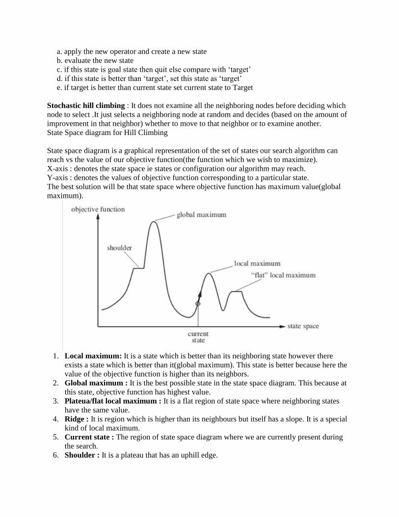
a. apply the new operator and create a new state
b. evaluate the new state
c. if this state is goal state then quit else compare with ‘target’
d. if this state is better than ‘target’, set this state as ‘target’
e. if target is better than current state set current state to Target
Stochastic hill climbing : It does not examine all the neighboring nodes before deciding which
node to select .It just selects a neighboring node at random and decides (based on the amount of
improvement in that neighbor) whether to move to that neighbor or to examine another.
State Space diagram for Hill Climbing
State space diagram is a graphical representation of the set of states our search algorithm can
reach vs the value of our objective function(the function which we wish to maximize).
X-axis : denotes the state space ie states or configuration our algorithm may reach.
Y-axis : denotes the values of objective function corresponding to a particular state.
The best solution will be that state space where objective function has maximum value(global
maximum).
1. Local maximum: It is a state which is better than its neighboring state however there
exists a state which is better than it(global maximum). This state is better because here the
value of the objective function is higher than its neighbors.
2. Global maximum : It is the best possible state in the state space diagram. This because at
this state, objective function has highest value.
3. Plateua/flat local maximum : It is a flat region of state space where neighboring states
have the same value.
4. Ridge : It is region which is higher than its neighbours but itself has a slope. It is a special
kind of local maximum.
5. Current state : The region of state space diagram where we are currently present during
the search.
6. Shoulder : It is a plateau that has an uphill edge.
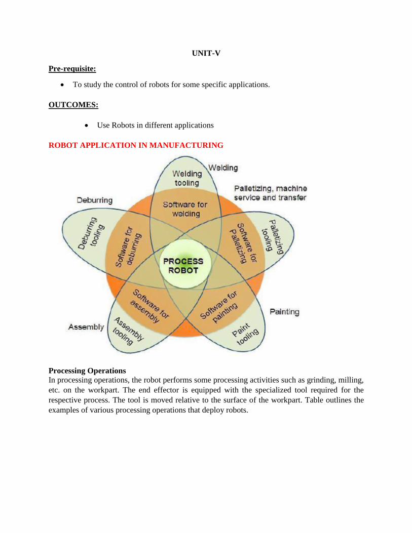
UNIT-V
Pre-requisite:
To study the control of robots for some specific applications.
OUTCOMES:
Use Robots in different applications
ROBOT APPLICATION IN MANUFACTURING
Processing Operations
In processing operations, the robot performs some processing activities such as grinding, milling,
etc. on the workpart. The end effector is equipped with the specialized tool required for the
respective process. The tool is moved relative to the surface of the workpart. Table outlines the
examples of various processing operations that deploy robots.
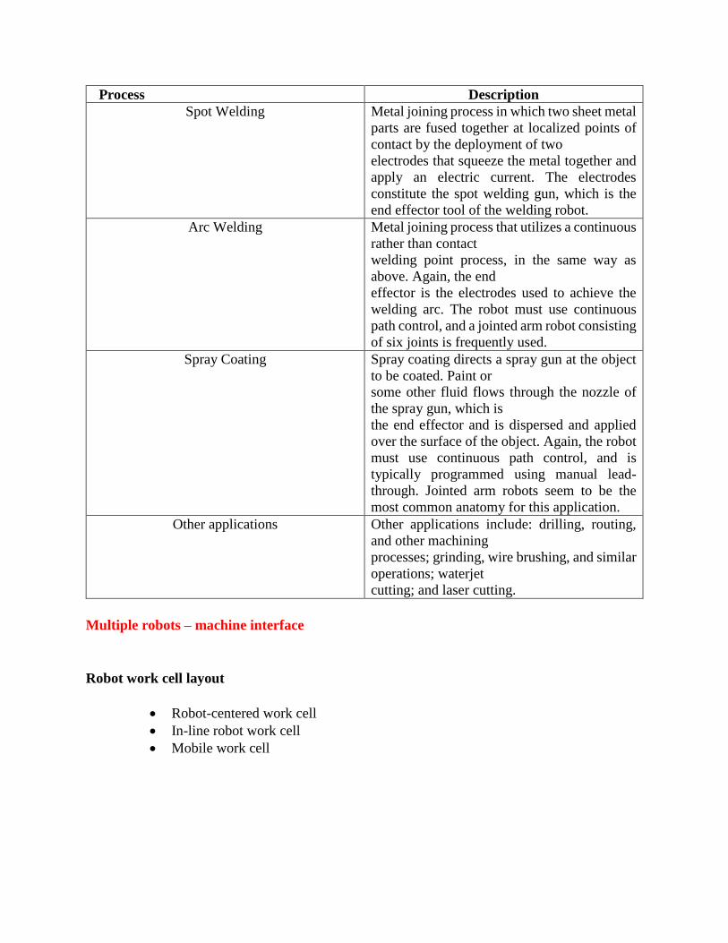
Process
Description
Spot Welding
Metal joining process in which two sheet metal
parts are fused together at localized points of
contact by the deployment of two
electrodes that squeeze the metal together and
apply an electric current. The electrodes
constitute the spot welding gun, which is the
end effector tool of the welding robot.
Arc Welding
Metal joining process that utilizes a continuous
rather than contact
welding point process, in the same way as
above. Again, the end
effector is the electrodes used to achieve the
welding arc. The robot must use continuous
path control, and a jointed arm robot consisting
of six joints is frequently used.
Spray Coating
Spray coating directs a spray gun at the object
to be coated. Paint or
some other fluid flows through the nozzle of
the spray gun, which is
the end effector and is dispersed and applied
over the surface of the object. Again, the robot
must use continuous path control, and is
typically programmed using manual lead-
through. Jointed arm robots seem to be the
most common anatomy for this application.
Other applications
Other applications include: drilling, routing,
and other machining
processes; grinding, wire brushing, and similar
operations; waterjet
cutting; and laser cutting.
Multiple robots – machine interface
Robot work cell layout
Robot-centered work cell
In-line robot work cell
Mobile work cell
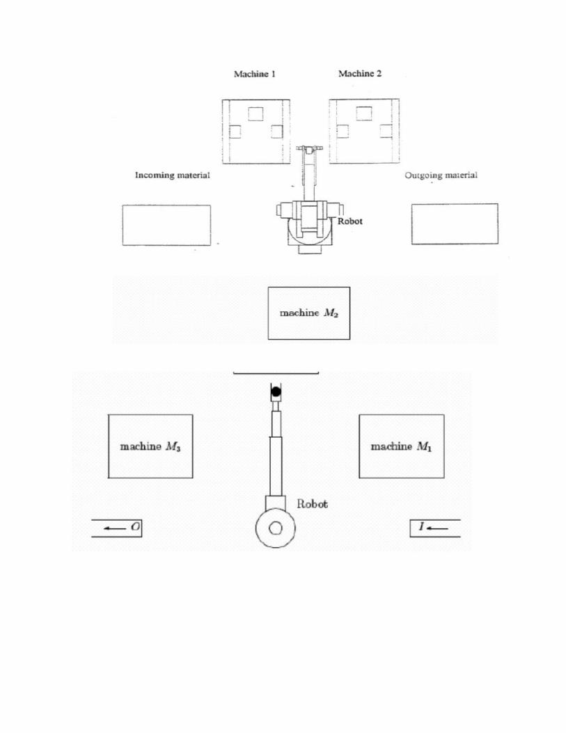
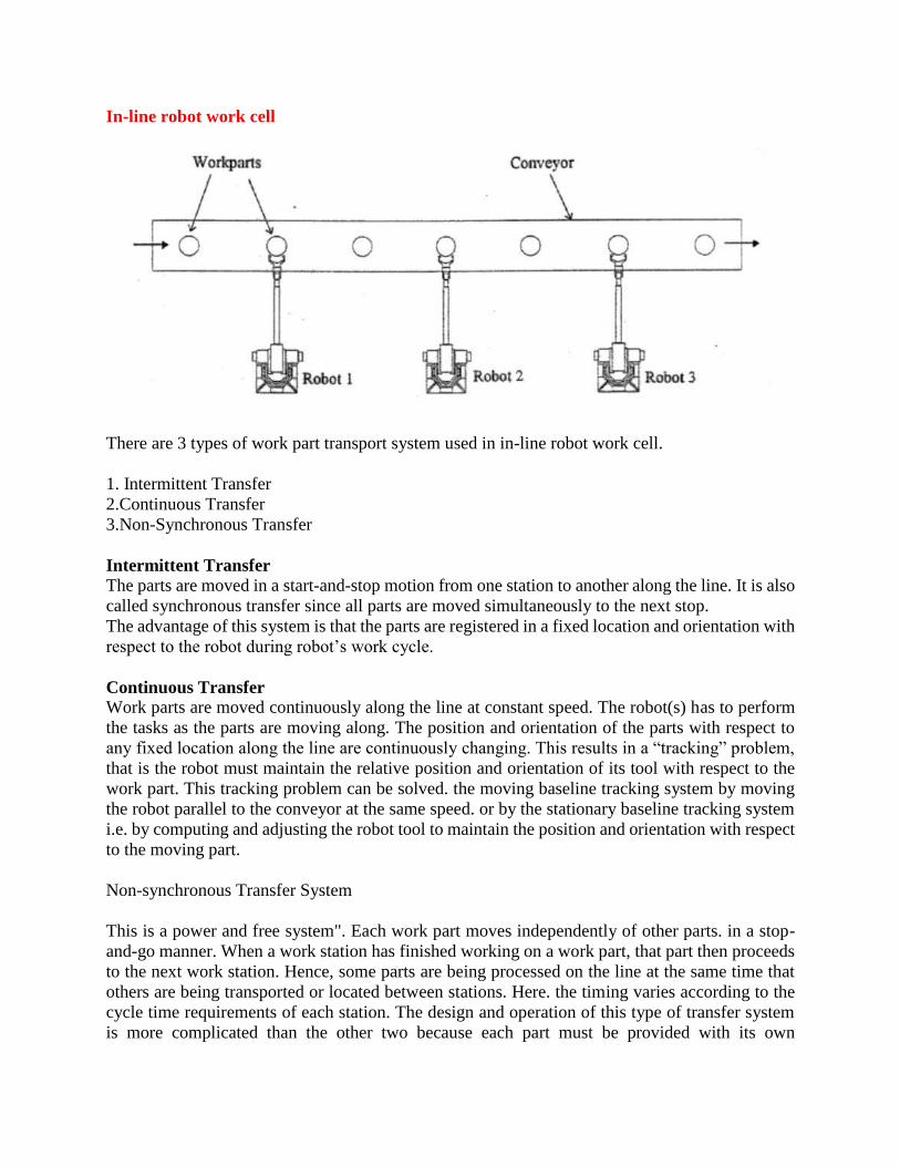
In-line robot work cell
There are 3 types of work part transport system used in in-line robot work cell.
1. Intermittent Transfer
2.Continuous Transfer
3.Non-Synchronous Transfer
Intermittent Transfer The parts are moved in a start-and-stop motion from one station to another along the line. It is also
called synchronous transfer since all parts are moved simultaneously to the next stop.
The advantage of this system is that the parts are registered in a fixed location and orientation with
respect to the robot during robot’s work cycle.
Continuous Transfer Work parts are moved continuously along the line at constant speed. The robot(s) has to perform
the tasks as the parts are moving along. The position and orientation of the parts with respect to
any fixed location along the line are continuously changing. This results in a “tracking” problem,
that is the robot must maintain the relative position and orientation of its tool with respect to the
work part. This tracking problem can be solved. the moving baseline tracking system by moving
the robot parallel to the conveyor at the same speed. or by the stationary baseline tracking system
i.e. by computing and adjusting the robot tool to maintain the position and orientation with respect
to the moving part.
Non-synchronous Transfer System
This is a power and free system". Each work part moves independently of other parts. in a stop-
and-go manner. When a work station has finished working on a work part, that part then proceeds
to the next work station. Hence, some parts are being processed on the line at the same time that
others are being transported or located between stations. Here. the timing varies according to the
cycle time requirements of each station. The design and operation of this type of transfer system
is more complicated than the other two because each part must be provided with its own
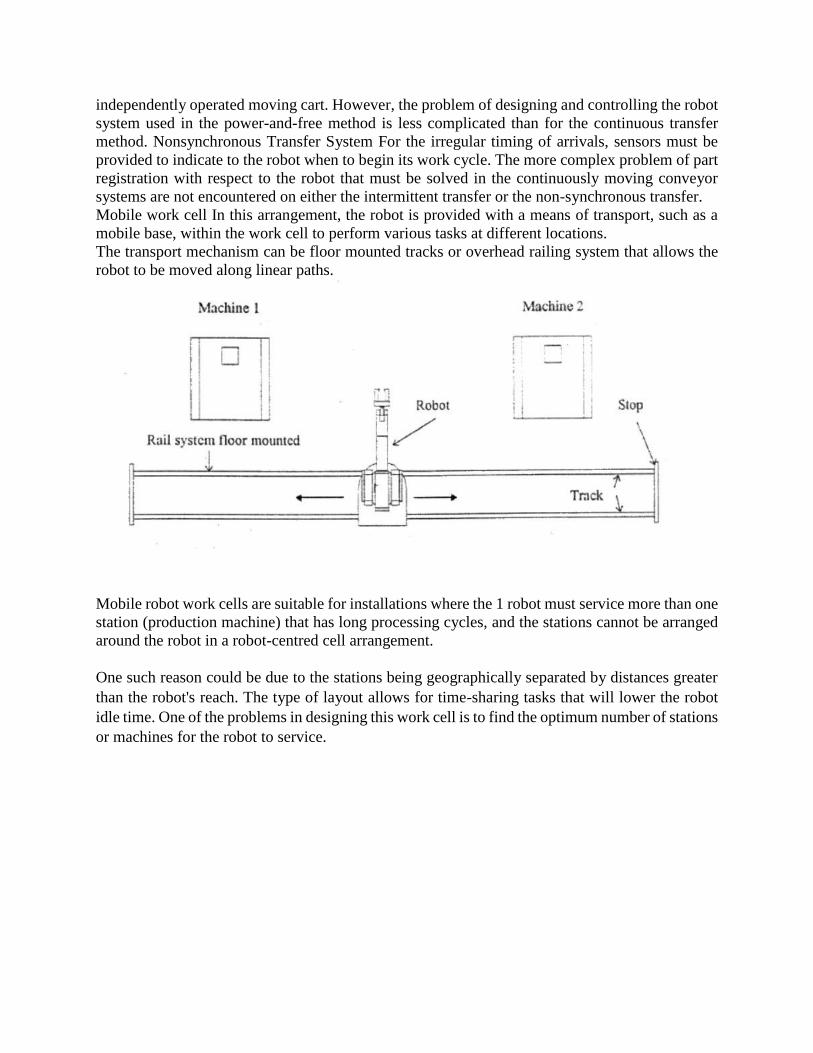
independently operated moving cart. However, the problem of designing and controlling the robot
system used in the power-and-free method is less complicated than for the continuous transfer
method. Nonsynchronous Transfer System For the irregular timing of arrivals, sensors must be
provided to indicate to the robot when to begin its work cycle. The more complex problem of part
registration with respect to the robot that must be solved in the continuously moving conveyor
systems are not encountered on either the intermittent transfer or the non-synchronous transfer.
Mobile work cell In this arrangement, the robot is provided with a means of transport, such as a
mobile base, within the work cell to perform various tasks at different locations.
The transport mechanism can be floor mounted tracks or overhead railing system that allows the
robot to be moved along linear paths.
Mobile robot work cells are suitable for installations where the 1 robot must service more than one
station (production machine) that has long processing cycles, and the stations cannot be arranged
around the robot in a robot-centred cell arrangement.
One such reason could be due to the stations being geographically separated by distances greater
than the robot's reach. The type of layout allows for time-sharing tasks that will lower the robot
idle time. One of the problems in designing this work cell is to find the optimum number of stations
or machines for the robot to service.
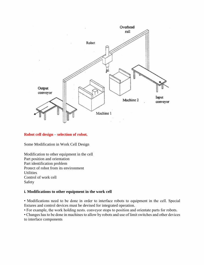
Robot cell design – selection of robot.
Some Modification in Work Cell Design
Modification to other equipment in the cell
Part position and orientation
Part identification problem
Protect of robot from its environment
Utilities
Control of work cell
Safety
i. Modifications to other equipment in the work cell
• Modifications need to be done in order to interface robots to equipment in the cell. Special
fixtures and control devices must be devised for integrated operation.
• For example, the work holding nests. conveyor stops to position and orientate parts for robots.
• Changes has to be done in machines to allow by robots and use of limit switches and other devices
to interface components
ii Part Position and Orientation
When parts are being delivered into the work cell, precise pick up locations along conveyors must
be established.
Parts must be in a known position and orientation for the robot to grasp accurately. As the parts
are being processed, the orientation must not be lost.
A way of achieving the above must be designed. For automated feeder systems, the design of the
way parts are being presented to the work cell must be provided for.
iii. Part Identification problem
It there are more than one type of parts, there will be a necessity to identify various parts by
automated means, suct as optical techniques. magnetic techniques or limit switches that sense
different sizes or geometry.
Electronic tagging may also be used with pallets so that the parts are identified by the information
carried by the information card.
iv. Protection of robot from its environment
In applications such as spray painting. hot metal working conditions. abrasive applications.
adhesive sealant applications, the robot has to be protected from possible adverse environment.
(e.g. use of sleeves. long grippers).
v. Utilities
Requirements for electricity. air and hydraulic pressures. gas for furnaces has to be considered and
provided for.
vi. Control of the work cell
The activities of the robot must be coordinated with those of the other equipment in the work cell.
Human protection measures such as fences, barriers, safety interrupt system with sensors in and
around the work cell must be provided.
This must be considered even at the early stages of the design of the work cell.
Work cell control
Sequence control
Operator interface
Safety monitoring
Sequence control
Sequence control includes:
Regulate the sequence of activities
Control of simultaneous activities
Making decision to proceed/stop/delay work based on events
In a work cell, the sequence of activities are as follows:
1. Robot picks up raw work part from conveyor at a known pick up location (machine idle)
2. Robot loads part into fixture at machining centre (machine idle).

3. Machining centre begins auto machining cycle (robot idle).
4. Machine completes auto machining. Robot unloads machine and places part on the machine on
pallet (machine idle).
5. Robot moves back to pick up point (machine idle)
Here almost all activities occur sequentially. Therefore, the controller must ensure activities occur
in correct sequence and that each step is completed before the next is started.
Notice that machine idle / robot idle is significant. If we fit a double gripper, productivity can be
further improved.
The modified sequence of activities (with double gripper fitted):
1. Robot picks up raw work part using the first gripper from conveyor at a known pick up location.
Robot moves its double gripper into ready position in front of machining centre (machine cycle in
progress).
2. At completion of machine cycle, robot unloads finished part from the machine fixture with a
second gripper and loads raw part into fixture with the first gripper (machine idle).
3. Machining centre begins auto machining cycle. Robot moves finished part to pallet and places
it in programmed location on pallet.
4. Robot moves back to pick up point (machine cycle in progress).
• In the modified sequence, several activities occur simultaneously but initiated sequentially.
Sequence Control
APPLICATION IN MANUFACTURING AND NON- MANUFACTURING
Robotic engineers are designing the next generation of robots to look, feel and act more human, to
make it easier for us to warm up to a cold machine. Realistic looking hair and skin with embedded
sensors will allow robots to react naturally in their environment.
Professional Robots in the field of Drug Delivery.

Rehabilitation
Tele Robots
Tele robotics is the area of robotics concerned with the control of semi-autonomous robots from a
distance, chiefly using Wireless network (like Wi-Fi, Bluetooth, the Deep Space Network, and
similar) or tethered connections. It is a combination of two major subfields, teleoperation and
telepresence

Laboratory Robots
Laboratory robotics is the act of using robots in biology or chemistry labs. For example,
pharmaceutical companies employ robots to move biological or chemical samples around to
synthesize novel chemical entities or to test
Hobbyist Robots
This category of robots are generally used for entertainment purpose and experimenting purpose.
These robots usually equipped with speech synthesis techniques.