Preparation and Characterization of Ti/rGO-RuO Electrode ...
12
Int. J. Electrochem. Sci., 13 (2018) 7870 – 7881, doi: 10.20964/2018.08.45 International Journal of ELECTROCHEMICAL SCIENCE www.electrochemsci.org Preparation and Characterization of Ti/rGO-RuO 2 Electrode for Hydrogen and Oxygen Evolution Reactions Xiaoyang Bao, Jiqing Bao * , Jie Xu, Cong Xu School of Biological and Chemical Engineering, Jiaxing University, Jiaxing 314001, China; * E-mail: [email protected] Received: 11 May 2018 / Accepted: 15 June 2018 / Published: 5 July 2018 This paper presents a preparation method of a graphene RuO 2 composite electrode. The electrode is obtained via electrochemical reduction of graphene oxide (GO) on a Ti substrate followed by thermal decomposition to prepare RuO 2 . According to results from SEM, CA curves, and EIS impedance, Ti/rGO-RuO 2 has many exposed active sites and good electrical conductivity. Ti/rGO-RuO 2 also shows excellent electrocatalytic performance for electrochemical water splitting (hydrogen evolution potential is -1.226 V and oxygen evolution potential is 0.842 V). After 10 h of electrolysis at 250 mA·cm -2 , the activity of Ti/rGO-RuO 2 showed no significant decrease for the hydrogen evolution reaction. In sum, Ti/rGO-RuO 2 contains an intermediate layer of graphene, has excellent application prospects in electrochemical water splitting, and has good application value in the field of hydroelectricity. Keywords: metal oxide anode; graphene; water splitting 1. INTRODUCTION Hydrogen has received increasing attention as a kind of clean and efficient energy. Electrochemical water splitting is considered to be an effective method for sustainably obtaining hydrogen. However, the energy consumption of electrolyzed water is large because of the presence of an overpotential. Catalysts are key to electrochemical water splitting technologies[1, 2] and have a direct impact on electrochemical reaction rates and overpotential. Thus, it is necessary to study electrode materials that have lower hydrogen overpotential. Pt is commonly used as a catalyst for the hydrogen evolution reaction (HER), and IrO 2 is used to accelerate the rate of the oxygen evolution reaction (OER). Pt has high catalytic activity and low HER overpotential and is a desirable material for electrochemical water splitting, but it is limited by its high cost. IrO 2 has poor reversibility, high
Transcript of Preparation and Characterization of Ti/rGO-RuO Electrode ...

Int. J. Electrochem. Sci., 13 (2018) 7870 – 7881, doi: 10.20964/2018.08.45
International Journal of
ELECTROCHEMICAL SCIENCE
www.electrochemsci.org
Preparation and Characterization of Ti/rGO-RuO2 Electrode
for Hydrogen and Oxygen Evolution Reactions
Xiaoyang Bao, Jiqing Bao
*, Jie Xu, Cong Xu
School of Biological and Chemical Engineering, Jiaxing University, Jiaxing 314001, China; *E-mail: [email protected]
Received: 11 May 2018 / Accepted: 15 June 2018 / Published: 5 July 2018
This paper presents a preparation method of a graphene RuO2 composite electrode. The electrode is
obtained via electrochemical reduction of graphene oxide (GO) on a Ti substrate followed by thermal
decomposition to prepare RuO2. According to results from SEM, CA curves, and EIS impedance,
Ti/rGO-RuO2 has many exposed active sites and good electrical conductivity. Ti/rGO-RuO2 also shows
excellent electrocatalytic performance for electrochemical water splitting (hydrogen evolution
potential is -1.226 V and oxygen evolution potential is 0.842 V). After 10 h of electrolysis at 250
mA·cm-2
, the activity of Ti/rGO-RuO2 showed no significant decrease for the hydrogen evolution
reaction. In sum, Ti/rGO-RuO2 contains an intermediate layer of graphene, has excellent application
prospects in electrochemical water splitting, and has good application value in the field of
hydroelectricity.
Keywords: metal oxide anode; graphene; water splitting
1. INTRODUCTION
Hydrogen has received increasing attention as a kind of clean and efficient energy.
Electrochemical water splitting is considered to be an effective method for sustainably obtaining
hydrogen. However, the energy consumption of electrolyzed water is large because of the presence of
an overpotential. Catalysts are key to electrochemical water splitting technologies[1, 2] and have a
direct impact on electrochemical reaction rates and overpotential. Thus, it is necessary to study
electrode materials that have lower hydrogen overpotential. Pt is commonly used as a catalyst for the
hydrogen evolution reaction (HER), and IrO2 is used to accelerate the rate of the oxygen evolution
reaction (OER). Pt has high catalytic activity and low HER overpotential and is a desirable material for
electrochemical water splitting, but it is limited by its high cost. IrO2 has poor reversibility, high

Int. J. Electrochem. Sci., Vol. 13, 2018
7871
overpotential, and large energy loss in water electrolysis[3]. Therefore, Pt and IrO2 cannot be widely
used in water splitting. RuO2 is a platinum-based metal oxide[4, 5] that has high catalytic activity.
Calculation results of RuO2 from X-ray photoelectron spectroscopy combined with density functional
theory (DFT) calculations show that the unsaturated Ru (CUS Ru) in RuO2 can reduce the energy
barrier in electrochemical reactions[6-8]. Rutile RuO2 accelerates the rate of OER and also has higher
catalytic activity for HER during water splitting[9, 10]. Furthermore, RuO2 can be coated on a Ti
substrate via thermal decomposition to prepare an electrode that has high activity and is low cost.
However, one of the major challenges of using RuO2 as an anode for water splitting is the bad stability;
RuO2 is oxidized to RuO4 and then dissolves, leading to the deactivation of RuO2. This is particularly a
problem on a dimensionally stable anode (DSA). Thus, enhancing the stability of RuO2 is the goal of
this study.
The electrocatalytic activity of an electrode generally depends on many factors, such as
accessibility to the active center, conductivity, and electrode geometry. Nanostructured materials are
the most direct way to improve electrocatalytic activity. To increase an electrochemical reaction rate,
researchers generally use conductive materials as a carrier to increase the active sites and conductivity
of a catalyst. Carbon nanomaterials that have excellent conductivity and specific surface area are
research hotspots for catalyst carriers, such as carbon nanotubes[11], carbon nanofibers[12],
nanocarbon[13], and graphene[14]. Graphene is a two-dimensional material with a large specific
surface area (2630 m2·g
-1)[15] that can provide a large number of catalytically active sites[16-18], can
be used for electrochemical reaction and excellent conductivity, can reduce contact resistance, and can
enhance electronic transmission capacity in batteries[19-21], photoelectrics[22], sensors[23], and
catalysts[24] in a wide range of applications. In addition, the excellent barrier properties[25] and
chemical inertness[26] of graphene allow it to be used in corrosion-resistant materials. Graphene can
be stacked to form a dense layer, which has a physical preservative effect on slowing or preventing
corrosion through the medium. Chen[27] deposited a graphene layer on Cu using chemical vapor
deposition (CVD), and the graphene-coated copper sheet exhibited extremely high oxidation resistance.
Therefore, graphene is also excellent in the field of corrosion protection.
In summary, the characteristics of graphene include anti-infiltration, anti-oxidation, high
specific surface area, and high conductance; thus, graphene can be used as a protective layer and a
conductive layer to improve electron transfer between the Ti substrate and RuO2 to obtain high
catalytic activity and low overpotential for the hydrogen evolution anode Ti/rGO-RuO2, which exhibits
superior activity and stability for OER and HER.
2. EXPERIMENTAL
2.1. Materials
RuCl3·xH2O (Ru 37 wt%) and natural graphite powder were obtained from Sinopharm
Chemical Reagent Co., Ltd. n-Butanol was used as a solvent to prepare all of the metal salt solutions.
Int. J. Electrochem. Sci., Vol. 13, 2018
7872
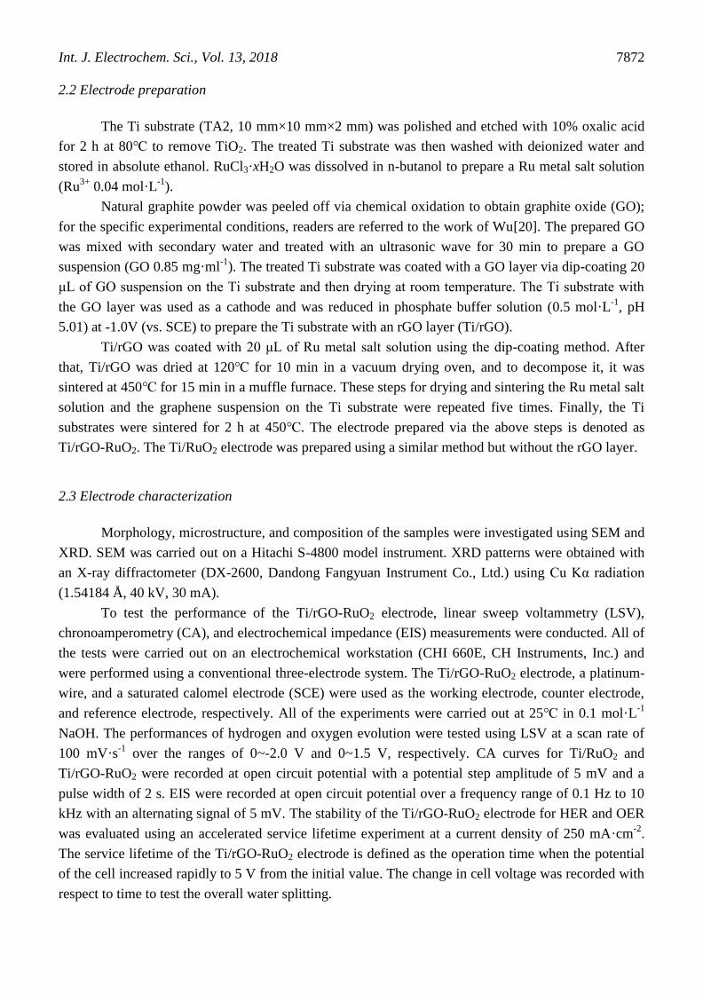
2.2 Electrode preparation
The Ti substrate (TA2, 10 mm×10 mm×2 mm) was polished and etched with 10% oxalic acid
for 2 h at 80℃ to remove TiO2. The treated Ti substrate was then washed with deionized water and
stored in absolute ethanol. RuCl3·xH2O was dissolved in n-butanol to prepare a Ru metal salt solution
(Ru3+
0.04 mol·L-1
).
Natural graphite powder was peeled off via chemical oxidation to obtain graphite oxide (GO);
for the specific experimental conditions, readers are referred to the work of Wu[20]. The prepared GO
was mixed with secondary water and treated with an ultrasonic wave for 30 min to prepare a GO
suspension (GO 0.85 mg·ml-1
). The treated Ti substrate was coated with a GO layer via dip-coating 20
μL of GO suspension on the Ti substrate and then drying at room temperature. The Ti substrate with
the GO layer was used as a cathode and was reduced in phosphate buffer solution (0.5 mol·L-1
, pH
5.01) at -1.0V (vs. SCE) to prepare the Ti substrate with an rGO layer (Ti/rGO).
Ti/rGO was coated with 20 μL of Ru metal salt solution using the dip-coating method. After
that, Ti/rGO was dried at 120℃ for 10 min in a vacuum drying oven, and to decompose it, it was
sintered at 450℃ for 15 min in a muffle furnace. These steps for drying and sintering the Ru metal salt
solution and the graphene suspension on the Ti substrate were repeated five times. Finally, the Ti
substrates were sintered for 2 h at 450℃. The electrode prepared via the above steps is denoted as
Ti/rGO-RuO2. The Ti/RuO2 electrode was prepared using a similar method but without the rGO layer.
2.3 Electrode characterization
Morphology, microstructure, and composition of the samples were investigated using SEM and
XRD. SEM was carried out on a Hitachi S-4800 model instrument. XRD patterns were obtained with
an X-ray diffractometer (DX-2600, Dandong Fangyuan Instrument Co., Ltd.) using Cu Kα radiation
(1.54184 Å, 40 kV, 30 mA).
To test the performance of the Ti/rGO-RuO2 electrode, linear sweep voltammetry (LSV),
chronoamperometry (CA), and electrochemical impedance (EIS) measurements were conducted. All of
the tests were carried out on an electrochemical workstation (CHI 660E, CH Instruments, Inc.) and
were performed using a conventional three-electrode system. The Ti/rGO-RuO2 electrode, a platinum-
wire, and a saturated calomel electrode (SCE) were used as the working electrode, counter electrode,
and reference electrode, respectively. All of the experiments were carried out at 25℃ in 0.1 mol·L-1
NaOH. The performances of hydrogen and oxygen evolution were tested using LSV at a scan rate of
100 mV·s-1
over the ranges of 0~-2.0 V and 0~1.5 V, respectively. CA curves for Ti/RuO2 and
Ti/rGO-RuO2 were recorded at open circuit potential with a potential step amplitude of 5 mV and a
pulse width of 2 s. EIS were recorded at open circuit potential over a frequency range of 0.1 Hz to 10
kHz with an alternating signal of 5 mV. The stability of the Ti/rGO-RuO2 electrode for HER and OER
was evaluated using an accelerated service lifetime experiment at a current density of 250 mA·cm-2
.
The service lifetime of the Ti/rGO-RuO2 electrode is defined as the operation time when the potential
of the cell increased rapidly to 5 V from the initial value. The change in cell voltage was recorded with
respect to time to test the overall water splitting.

Int. J. Electrochem. Sci., Vol. 13, 2018
7873
3. RESULTS AND DISCUSSION
3.1. Surface morphology and crystal structure
Figure 1. SEM micrographs: (a) Ti substrate, (b) Ti/rGO, and (c) Ti/RuO2 after coating and sintering
the Ru metal salt solution one time; (d) Ti/rGO-RuO2 after coating and sintering the Ru metal
salt solution one time; (e) Ti/RuO2 after coating and sintering the Ru metal salt solution 5
times; (f) Ti/rGO-RuO2 after coating and sintering the Ru metal salt solution 5 times.
Figures 1a and b show SEM images of the Ti substrate and Ti/rGO electrode. The surface of the
Ti substrate that is not coated with graphene is flat. After electrochemical reduction of graphene oxide,
the Ti substrate surface is covered with a layer of graphene (Figure 1b). After coating and sintering the
Ru metal solution one time, a complete and smooth RuO2 layer formed on the surface of the Ti
substrate (Figure 1c), whereas a curled RuO2 layer formed on Ti/rGO (Figure 1d). Finally, after coating
and sintering 5 times, the surfaces of both Ti/RuO2 and Ti/rGO-RuO2 were completely covered with
RuO2; numerous convex RuO2 particles appeared on the surface of Ti/RuO2 and Ti/rGO-RuO2, but the
particles of Ti/rGO-RuO2 were finer than those of Ti/RuO2, and this indicates that RuO2 crystal growth

Int. J. Electrochem. Sci., Vol. 13, 2018
7874
was controlled after the addition of graphene. The specific surface area of Ti/rGO-RuO2 is bigger than
that of Ti/RuO2, and thus, it is more conducive to water splitting.
Ti/rGO-RuO2 and Ti/RuO2 were analyzed using X-ray crystal diffraction to study the crystal
structure of the material. As shown in Figure 2, there were two diffraction peaks at 2θ = 27.9° and
35.3°, and these correspond to RuO2. The crystalline grain diameters were calculated according to the
Scherrer formula using the half height width of the main diffraction peaks at 2θ = 27.9° and 35.3°, and
the results are shown in Table 1. The crystalline grain diameters show that introducing the rGO layer
into the RuO2 coating decreased the size of the RuO2 particles. Smaller sized crystal particles means
higher catalytic activity, and thus, the catalytic activity of Ti/rGO-RuO2 is better than that of Ti/RuO2.
Furthermore, there were diffraction peaks for Ti at 2θ = 38.4°, 40.0°, 53.0°, 63.0°, 70.5°, 76.2°, and
77.4° because the X-ray penetrated the coating and reached the Ti substrate.
Table 1. Crystalline grain diameters of the Ti/RuO2 and Ti/rGO-RuO2 electrodes.
Electrode Half height width (101 plane) Crystallite size (101 plane)/nm
Ti/RuO2 0.469 18.2
Ti/rGO-RuO2 0.503 16.9
Figure 2. XRD spectra of the Ti/RuO2 and Ti/rGO-RuO2 electrodes.
3.2 Electrocatalytic hydrogen evolution
The electrocatalytic activity of Ti/rGO-RuO2 for water splitting was tested in 0.1 mol·L-1
NaOH using a three-electrode system. As seen in Figure 3a, the current density is too low before HER,
and thus, the polarization potential at 10 mA·cm-2
(Ej=10) was used as a reference to compare
performances of the Ti/RuO2 and Ti/rGO-RuO2 electrodes. The hydrogen evolution potential (HEP) of
the Ti/rGO-RuO2 electrode is -1.226 V, which is lower than that of the Ti/RuO2 electrode (-1.409 V)
and that of the Pt electrode (-1.435 V). This indicates that it is easier to carry out HER on the Ti/rGO-
RuO2 electrode. At the same time, the reaction current of the Ti/rGO-RuO2 electrode increased rapidly

Int. J. Electrochem. Sci., Vol. 13, 2018
7875
over the potential range of -1.2 ~ -2.0 V, had a growth rate of 204.9 mA·V-1
, and had higher HER. The
Ti/rGO-RuO2 electrode has a lower Tafel slope (-93 mV·dec-1
) compared to the Ti/RuO2 (-149
mV·dec-1
) and Pt (-134 mV·dec-1
) electrodes, and so this indicates that the Ti/rGO-RuO2 electrode has
excellent hydrogen evolution activity. In comparison to other reported electrodes[28-32] listed in Table
2, Ti/rGO-RuO2 has excellent HER activity. The above results are evidence that Ti/rGO-RuO2 has
better performance for HER.
Table 2. HEP of the Ti/rGO-RuO2 electrode and other reported DSAs.
Electrolyte
Ej=10/V
vs.SCE vs.RHE
Ti/rGO-RuO2 (this work) 0.1 mol·L-1
NaOH -1.226 -0.213
Ti/RuO2 (this work) 0.1 mol·L-1
NaOH -1.409 -0.396
Pt (this work) 0.1 mol·L-1
NaOH -1.435 -0.422
Prorous Co phosphide/Phoshate (ref.[28]) 1.0 mol·L-1
KOH -1.393 -0.380
Ni2S3 nanosheet array (ref.[29]) 1.0 mol·L-1
NaOH -1.236 -0.223
Co/CoO/N-doped Carbon(ref.[30]) 1.0 mol·L-1
NaOH -1.248 -0.235
CoSe/NiFe LDH(ref.[31]) 1.0 mol·L-1
KOH -1.273 -0.260
Cobalt-Embedded Nitrogen-Rich Carbon Nanotubes(ref.[32]) 1.0 mol·L-1
KOH -1.383 -0.370
There are two reasons for the excellent electrochemical activity of Ti/rGO-RuO2. First, the higher
catalytic HER activity of Ti/rGO-RuO2 is probably due to the higher specific surface area. As seen in
the SEM images shown in Figure. 1, there are more and smaller convex particles on the Ti/rGO-RuO2
coating; these enable the coating to be rougher, and this improves the number of active sites[33, 34].
Second, the rGO interlayer improves the coating conductivity. Thus, the EIS and CA curves of Ti/rGO-
RuO2 were further analyzed to prove the excellent conductivity and the number of active sites of
Ti/rGO-RuO2.
The CA curve was used to assess the electrochemically active surface area (ECSA) of the
electrode. When the electrode is immersed in electrolyte, an electrochemical double-layer capacitance
(EDLC) forms at the interface between the electrode and solution and is proportional to the number of
exposed active sites[18, 35]. The CA curve of Ti/rGO-RuO2 (Figure 3c) was measured at open circuit
potential with a signal amplitude of 5 mV and a step time of 2 s. The EDLC and real surface area were
calculated using equations (1) and (2)[36]:
(1)
where Cd represents the electric double-layer capacitance (F), t represents the step time (s), I represents
the response current (A), and represents the signal amplitude (V).
(2)
where Sr represents the real surface area (cm2), Cd represents the electric double-layer capacitance (F),
and CHg=20 μF·cm-2
represents the EDLC of pure mercury per unit area.
The EDLC results and Sr are shown in Figure 2c. The EDLC of the Ti/rGO-RuO2 electrode is
higher than that of Ti/RuO2, which indicates that there are more exposed active sites on Ti/rGO-RuO2.

Int. J. Electrochem. Sci., Vol. 13, 2018
7876
The real surface area of the Ti/rGO-RuO2 electrode is 475.8 cm2, and this value is 1.4 times greater
than that of Ti/RuO2 (342.1 cm2); the surface roughness is also larger. Therefore, the rGO interlayer
increased the active sites on the surface and improved its electrocatalytic activity of the Ti/rGO-RuO2
electrode[37].
To further investigate the electrochemical properties of the electrodes, EIS measurements were
performed at open circuit potential in 0.1 mol·L-1
NaOH over the frequency range of 100 kHz to 1 Hz
with an alternating signal of 5 mV. The EIS results are shown in Figure 2d. The fitting of the EIS
results was described using an equivalent circuit represented by Rs(RfCf)(RctCdl)W, as shown in the
inset of Figure 2d. In this circuit, Rs represents the solution resistance, Rf is the coating resistance, Cf is
the coating capacitance, Cdl is the pseudo-capacitance of the double-layer, and Rct is the charge transfer
resistance[38, 39]. The behaviors of the circuit elements are given in Table 3, where it can be seen that
the value of Rf for the Ti/rGO-RuO2 electrode was lower than that for the Ti/RuO2 electrode. This
indicates that the rGO interlayer improved the conductivity of the coating. It is important to note that
the charge transfer resistance (Rct) decreased for the Ti/rGO-RuO2 electrode, and thus, Ti/rGO-RuO2
has higher activity for HER. In the electrocatalytic process, high conductivity can promote charge
transfer and thus contribute to the high activity of Ti/rGO-RuO2[40].These behaviors indicate that
graphene increases the electron transfer between Ti and RuO2, thereby increasing the electrocatalytic
activity of Ti/rGO-RuO2.
Table 3. Impedance parameters of the Ti/RuO2 and Ti/rGO-RuO2 electrodes.
Rs/Ω·cm2 Rf/Ω·cm
2 Cf/F·cm
-2 Rct/Ω·cm
2 Cdl/F·cm
-2 W/s·sec^
5·cm
2 χ
2
Ti/RuO2 33.68 104.7 3.65×10⁻³
5.203 9.464×10⁻⁵
7.966×10⁻³
2.63×10⁻⁴
Ti/rGO-RuO2 30.53 98.92 3.366×10⁻³
4.975 7.939×10⁻⁵
1.311×10⁻²
2.31×10⁻⁴
The stability of the electrode is a great reference value for industrial applications. The hydrogen
evolution polarization curve of Ti/rGO-RuO2 was tested after 1000 cycles from -1.2 to 0 V at a scan
rate of 100 mV·s-1
in 0.1 mol·L-1
NaOH solution. As seen in Figure 3e, the electrocatalytic activity of
Ti/rGO-RuO2 changed only slightly after 1000 cycles, and the polarization curve of hydrogen
evolution was almost the same as the original polarization curve. The change in electrode potential at a
constant current density (250 mA·cm-2
) is shown in Figure 3f. After 1 h of electrolysis, the activities of
Pt, Ti/RuO2, and Ti/rGO-RuO2 reached equilibrium, and the potentials were -4.617, -4.250, and -3.928
V, respectively. The potential of Ti/rGO-RuO2 has a significant fluctuation because its excellent
hydrogen evolution activity rapidly generates hydrogen, which adheres on the surface. This is
particularly a problem in water splitting because gases are generated that can potentially block active
sites and prohibit ionic transportation, and this is one of the major sources of overpotential. After 10 h,
the surface potential of Ti/rGO-RuO2 did not change obviously. All of the results show that Ti/rGO-
RuO2 has good stability as a hydrogen evolution catalyst. Ti/rGO-RuO2 has high surface potential; thus,
there is lower power consumption, and it is an excellent hydrogen evolution catalytic material.

Int. J. Electrochem. Sci., Vol. 13, 2018
7877
Figure 3. Electrocatalytic properties of Ti/rGO-RuO2 for HER: (a) LSV plots obtained with Ti/RuO2,
Ti/rGO-RuO2, and Pt for HER at 10 mV·s-1
in 0.1 mol·L-1
NaOH. (b) Tafel plots obtained with
Ti/RuO2, Ti/rGO-RuO2, and Pt. (c) CA curves of Ti/RuO2 and Ti/rGO-RuO2 at open circuit
potential with a potential step amplitude of 5 mV and pulse width of 2 s. (d) EIS spectra of
Ti/RuO2 and Ti/rGO-RuO2 at open circuit potential over the frequency range of 0.1 Hz to 10
kHz with an alternating signal of 5 mV. (e) LSV plots of Ti/rGO-RuO2 for HER obtained
before and after 1000 cycles of cyclic voltammetry from 0 to -1.2 V (vs. SCE) with a scan rate
of 100 mV·s-1
. (f) Chronopotentiometry of Ti/RuO2, Ti/rGO-RuO2, and Pt for 10 h at 250
mA·cm-2
in 0.1 mol·L-1
NaOH.
3.3 Electrocatalytic oxygen evolution
Ti/rGO-RuO2 also has high activity for OER. Figure 4a shows the Ti/rGO-RuO2 oxygen
evolution polarization curve. The oxygen evolution potential (OEP) is 0.842 V at a current density of

Int. J. Electrochem. Sci., Vol. 13, 2018
7878
10 mA·cm-2
, whereas that of Ti/RuO2 is 0.886 V. This change can be caused by the excellent coating
conductivity of Ti/rGO-RuO2, as noted in the EIS analysis. The difference in OEP between Ti/rGO-
RuO2 and Ti/RuO2 indicate that Ti/rGO-RuO2 has obvious activity for OER. The reaction current
growth rate of Ti/rGO-RuO2 was 39.1 mA·V-1
at 0.8-1.0 V but slows to 34.5 mA·V-1
in the range of
1.3-1.5 V. This is because the rate of OER for RuO2 in alkaline solution is limited by Ru4+
-OH+OH-
→Ru5+
-O+H2O+e-[41]. The low concentration of OH
- in the electrolyte leads to a diffusion rate that
cannot meet the requirement for OER, and thus, the current growth rate of Ti/rGO-RuO2 decreases
with an increase in potential.
To investigate the stability of Ti/rGO-RuO2 for OER, Ti/rGO-RuO2 was used as an anode for
electrolysis at a constant current density of 250 mA·cm-2
until the cell voltage increased by 5V. For
comparison, Ti/RuO2 was also tested using the same conditions. The results for this experiment are
shown in Figure 4b. The continuous oxygen evolution time of Ti/rGO-RuO2 is 11.4 h, whereas the
oxygen evolution time of Ti/RuO2 without a graphene layer is 9.2 h; this indicates that the stability of
Ti/rGO-RuO2 for OER is better. According to a study by Chang[42], failure of electrodes is mainly
caused by the formation of insulating TiO2. However, the rGO layer in Ti/rGO-RuO2 is a conductive
material with anti-oxidation ability and molecular penetration; thus, the problem of the formation of an
insulating TiO2 layer is alleviated and the service life of Ti/rGO-RuO2 is prolonged.
Figure 4. Electrocatalytic properties of Ti/rGO-RuO2 for OER: (a) LSV plots obtained with Ti/RuO2
and Ti/rGO-RuO2 for OER at 10 mV·s-1
in 0.1 mol·L-1
NaOH and (b) chronopotentiometry of
Ti/RuO2, Ti/rGO-RuO2, and Pt for 10 h at 250 mA·cm-2
in 0.1 mol·L-1
NaOH.
Ti/rGO-RuO2 electrodes were used as the anode and cathode to build a two-electrode cell to
test overall water splitting. Figure 5 shows that the current density of the electrolysis cell constructed
using the Ti/rGO-RuO2 electrodes increased rapidly, and the current density has a linear relationship
with the electrolysis cell voltage. Under the same conditions, the growth rate of the Ti/RuO2 current
density decreases with an increase in cell voltage, and this indicates that the reaction rate on Ti/RuO2
reaches a limit. The electrolytic cell constructed using the Ti/rGO-RuO2 electrodes demonstrated
excellent catalytic activity and delivered a current density of 34.3 mA·cm-2
with an applied voltage of
3.0 V. This current density is higher than that of Ti/rGO-RuO2 (23.0 mA·cm-2
), and therefore, Ti/rGO-
RuO2 can lower energy consumption for the water electrode reaction.

Int. J. Electrochem. Sci., Vol. 13, 2018
7879
Figure 5. Current density of an electrolytic cell using Ti/rGO-RuO2 electrodes as the anode and
cathode at different cell voltages in 0.1 mol·L-1
NaOH.
4. CONCLUSIONS
In summary, this paper presents the Ti/rGO-RuO2 electrode for overall water splitting. The
Ti/rGO-RuO2 electrode is prepared using a method in which the Ti substrate is covered with
electrochemically reduced GO then coated with RuO2 via thermal decomposition. This method can be
easily industrialized. The prepared Ti/rGO-RuO2 electrode has many excellent properties such as high
catalytic activity; it also has high stability for electrochemical reactions (OER and HER). According to
SEM images, adding an rGO layer as an intermediate layer leads to the formation of finer RuO2
particles on the surface of the Ti/rGO-RuO2 electrode, and this provides more active sites as catalytic
centers. The CA curve shows that the real surface area of the Ti/rGO-RuO2 electrode is larger than that
of Ti/RuO2; specifically, it is 1.4 times larger than that of Ti/RuO2. At an applied current density of 10
mA·cm-2
, Ti/rGO-RuO2 has a lower HEP of -1.226 V and OEP of 0.842 V compared to Ti/rGO-RuO2.
In addition, the EIS of Ti/rGO-RuO2 indicates that the graphene layer decreases the coating resistance
(Rf) and the coating transfer resistance (Rct), and this enables the current to react more efficiently
through the metal sites. Therefore, Ti/rGO-RuO2 has obviously high catalytic activity.
ACKNOWLEDEGMENT
The authors gratefully acknowledge the financial support of the Zhejiang Province Nature Science
Foundation of China under grant number LY18E040002.
References
1. S. Siracusano, V. Baglio, A.D. Blasi, N. Briguglio, A. Stassi, R. Ornelas, E. Trifoni, V. Antonucci,
A.S. Aricò, International Journal of Hydrogen Energy, 35 (2010) 5558.
2. A.A. Gewirth, M.S. Thorum, Cheminform, 49 (2010) 3557.
3. F.D. Kong, S. Zhang, G.P. Yin, Z.B. Wang, C.Y. Du, G.Y. Chen, N. Zhang, International Journal of
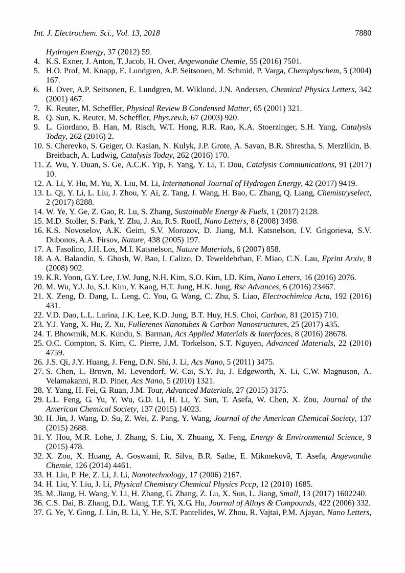
Int. J. Electrochem. Sci., Vol. 13, 2018
7880
Hydrogen Energy, 37 (2012) 59.
4. K.S. Exner, J. Anton, T. Jacob, H. Over, Angewandte Chemie, 55 (2016) 7501.
5. H.O. Prof, M. Knapp, E. Lundgren, A.P. Seitsonen, M. Schmid, P. Varga, Chemphyschem, 5 (2004)
167.
6. H. Over, A.P. Seitsonen, E. Lundgren, M. Wiklund, J.N. Andersen, Chemical Physics Letters, 342
(2001) 467.
7. K. Reuter, M. Scheffler, Physical Review B Condensed Matter, 65 (2001) 321.
8. Q. Sun, K. Reuter, M. Scheffler, Phys.rev.b, 67 (2003) 920.
9. L. Giordano, B. Han, M. Risch, W.T. Hong, R.R. Rao, K.A. Stoerzinger, S.H. Yang, Catalysis
Today, 262 (2016) 2.
10. S. Cherevko, S. Geiger, O. Kasian, N. Kulyk, J.P. Grote, A. Savan, B.R. Shrestha, S. Merzlikin, B.
Breitbach, A. Ludwig, Catalysis Today, 262 (2016) 170.
11. Z. Wu, Y. Duan, S. Ge, A.C.K. Yip, F. Yang, Y. Li, T. Dou, Catalysis Communications, 91 (2017)
10.
12. A. Li, Y. Hu, M. Yu, X. Liu, M. Li, International Journal of Hydrogen Energy, 42 (2017) 9419.
13. L. Qi, Y. Li, L. Liu, J. Zhou, Y. Ai, Z. Tang, J. Wang, H. Bao, C. Zhang, Q. Liang, Chemistryselect,
2 (2017) 8288.
14. W. Ye, Y. Ge, Z. Gao, R. Lu, S. Zhang, Sustainable Energy & Fuels, 1 (2017) 2128.
15. M.D. Stoller, S. Park, Y. Zhu, J. An, R.S. Ruoff, Nano Letters, 8 (2008) 3498.
16. K.S. Novoselov, A.K. Geim, S.V. Morozov, D. Jiang, M.I. Katsnelson, I.V. Grigorieva, S.V.
Dubonos, A.A. Firsov, Nature, 438 (2005) 197.
17. A. Fasolino, J.H. Los, M.I. Katsnelson, Nature Materials, 6 (2007) 858.
18. A.A. Balandin, S. Ghosh, W. Bao, I. Calizo, D. Teweldebrhan, F. Miao, C.N. Lau, Eprint Arxiv, 8
(2008) 902.
19. K.R. Yoon, G.Y. Lee, J.W. Jung, N.H. Kim, S.O. Kim, I.D. Kim, Nano Letters, 16 (2016) 2076.
20. M. Wu, Y.J. Ju, S.J. Kim, Y. Kang, H.T. Jung, H.K. Jung, Rsc Advances, 6 (2016) 23467.
21. X. Zeng, D. Dang, L. Leng, C. You, G. Wang, C. Zhu, S. Liao, Electrochimica Acta, 192 (2016)
431.
22. V.D. Dao, L.L. Larina, J.K. Lee, K.D. Jung, B.T. Huy, H.S. Choi, Carbon, 81 (2015) 710.
23. Y.J. Yang, X. Hu, Z. Xu, Fullerenes Nanotubes & Carbon Nanostructures, 25 (2017) 435.
24. T. Bhowmik, M.K. Kundu, S. Barman, Acs Applied Materials & Interfaces, 8 (2016) 28678.
25. O.C. Compton, S. Kim, C. Pierre, J.M. Torkelson, S.T. Nguyen, Advanced Materials, 22 (2010)
4759.
26. J.S. Qi, J.Y. Huang, J. Feng, D.N. Shi, J. Li, Acs Nano, 5 (2011) 3475.
27. S. Chen, L. Brown, M. Levendorf, W. Cai, S.Y. Ju, J. Edgeworth, X. Li, C.W. Magnuson, A.
Velamakanni, R.D. Piner, Acs Nano, 5 (2010) 1321.
28. Y. Yang, H. Fei, G. Ruan, J.M. Tour, Advanced Materials, 27 (2015) 3175.
29. L.L. Feng, G. Yu, Y. Wu, G.D. Li, H. Li, Y. Sun, T. Asefa, W. Chen, X. Zou, Journal of the
American Chemical Society, 137 (2015) 14023.
30. H. Jin, J. Wang, D. Su, Z. Wei, Z. Pang, Y. Wang, Journal of the American Chemical Society, 137
(2015) 2688.
31. Y. Hou, M.R. Lohe, J. Zhang, S. Liu, X. Zhuang, X. Feng, Energy & Environmental Science, 9
(2015) 478.
32. X. Zou, X. Huang, A. Goswami, R. Silva, B.R. Sathe, E. Mikmekovã, T. Asefa, Angewandte
Chemie, 126 (2014) 4461.
33. H. Liu, P. He, Z. Li, J. Li, Nanotechnology, 17 (2006) 2167.
34. H. Liu, Y. Liu, J. Li, Physical Chemistry Chemical Physics Pccp, 12 (2010) 1685.
35. M. Jiang, H. Wang, Y. Li, H. Zhang, G. Zhang, Z. Lu, X. Sun, L. Jiang, Small, 13 (2017) 1602240.
36. C.S. Dai, B. Zhang, D.L. Wang, T.F. Yi, X.G. Hu, Journal of Alloys & Compounds, 422 (2006) 332.
37. G. Ye, Y. Gong, J. Lin, B. Li, Y. He, S.T. Pantelides, W. Zhou, R. Vajtai, P.M. Ajayan, Nano Letters,

Int. J. Electrochem. Sci., Vol. 13, 2018
7881
16 (2016) 1097.
38. S.M. Hoseinieh, F. Ashrafizadeh, Ionics, 19 (2013) 113.
39. S.M. Hoseinieh, F. Ashrafizadeh, M.H. Maddahi, Journal of the Electrochemical Society, 157
(2010) E50.
40. J. Duan, S. Chen, C. Zhao, Nature Communications, 8 (2017) 15341.
41. R.R. Rao, M.J. Kolb, N.B. Halck, A.F. Pedersen, A. Mehta, H. You, K.A. Stoerzinger, Z. Feng, H.A.
Hansen, H. Zhou, Energy & Environmental Science, 10 (2017) 2626.
42. L. Chang, Y. Zhou, X. Duan, W. Liu, D. Xu, Journal of the Taiwan Institute of Chemical Engineers,
45 (2014) 1338.
© 2018 The Authors. Published by ESG (www.electrochemsci.org). This article is an open access
article distributed under the terms and conditions of the Creative Commons Attribution license
(http://creativecommons.org/licenses/by/4.0/).