
PREMIER TRANSMISSION LTD - Mutual Energy · 2 PREMIER TRANSMISSION LIMITED STATEMENT OF CONNECTION...
21
1 PREMIER TRANSMISSION LTD Connection Policy Rev 4 - 2nd July 2001
Transcript of PREMIER TRANSMISSION LTD - Mutual Energy · 2 PREMIER TRANSMISSION LIMITED STATEMENT OF CONNECTION...

1
PREMIER TRANSMISSION LTD
Connection Policy
Rev 4 - 2nd July 2001
2
PREMIER TRANSMISSION LIMITED
STATEMENT OF CONNECTION POLICY
INDEX
Page
1. INTRODUCTION 1 - Who can request a connection? 2 2. ENTRY CONNECTIONS 3 3. EXIT CONNECTIONS 3 - Connections from the Network 3 - Minimum requirements 4 - Connection of Measurement Equipment 4 - Other requirements 4 4. OUTLINE TECHNICAL SPECIFICATION FOR A CONNECTION 6 5. FILTER FUNCTIONAL SPECIFICATION 7 6. GAS QUALITY & FLOW MEASUREMENT SPECIFICATION 7 - Gas Quality 7 - Energy Calculation 7 - CV Measurement 8 - Flow Measurement 8 - Communications Interface 8 - Other issues to be agreed by PTL 9 7. CONNECTION COSTS 9 8. COMMERCIAL ARRANGEMENTS 11 - Construction Stage 11 - Transportation Stage 12 9. OTHER ARRANGEMENTS 12 APPENDIX 1 – Draft Offtake Provisions Agreement APPENDIX 2 - Draft Connection Agreement APPENDIX 3 - Indicative Costs of Connections APPENDIX 4 – Connections Process Flow Diagram

3
1. INTRODUCTION
The licence granted by OFREG to Premier Transco Limited (Later Premier Transmission Limited) for the conveyance and supply of gas includes condition (2.2) that requires PTL to issue a statement of policy regarding connection charges, terms for connection and meter connections and disconnections. A copy of the PTL Licence can be obtained at a cost of £10 from Ofreg at Brookmount Buildings, 42 Fountain Street, Belfast. This document is designed to fulfil this licence requirement. Under condition 2.2.4 of the licence, PTL is required to publish this statement and forward a copy to anyone who asks for it.
This document sets out the charging and policy requirements for future connections to introduce gas to (entry) and take gas from (exit) the 24" high pressure transmission pipeline owned and operated by Premier Transmission Ltd. (PTL) running for approximately 3km from (and including) the low water mark at Castle Robin Bay to (and including) the pressure reduction station site within the inner security fence at Ballylumford Power Station ("the Network"). This statement is prepared under Condition 2.4 of PTL's license for the conveyance of gas. As the Network Operator, Premier Transmission Limited has a Transportation Code (to be implemented from 1st October 2000) which contains the terms for the conveyance of gas through the Network. This statement sets out the requirements for connections both to individual premises and to connected pipeline systems. The statement also covers connections to meters not owned by PTL, within individual premises.
The statement sets out what at this stage are the minimum requirements for all new connections to the Network. PTL is committed to working with OFREG and other interested parties to develop this new regime for connections to the Network.
PTL's policy is that the full capital costs of any entry connection, including project management costs, would be borne by the party wishing to connect to the Network. Given the individual nature and complexity of such connections, PTL propose that these would be approached on a case by case basis. All connections will need to meet the minimum technical requirements detailed within this document.
1.2 Who can request a Connection?
PTL will enter into discussions with all bonafide shippers and their customers for the provision of a connection to its system. For the purposes of this Policy a Bona-Fide shipper shall be defined as:

4
a person other than Premier Transmission who, for the time being, has acceded to and is bound by the PTL Transportation Code by an Accession Agreement; (a "Shipper" as defined by the Transportation Code)
or any person wishing to become a Shipper (a “Prospective Shipper” as defined by the PTL Transportation Code).
or any prospective shipper who is planning his network and can provide satisfactory evidence of either: (a) an Exit Point Registration (b) a Downstream Load Statement (c) an Indicative Application for Capacity Reservation. (d) discussions regarding the supply of gas to a customer via the PTL pipeline such as: • Providing details of agreed contracts to supply gas to a premises • Providing details of a legally binding MOU or similar device demonstrating a strong
intent to enter into such a contract.
In all cases these parties shall meet the full costs of making the connection. No differentiation will be made between classes of interested parties and no element of such connection capital costs will be passed on to other users of the PTL Network. There are a number of different types of Customer who can request a connection from PTL, these include:
Any owner or occupier of premises to be connected.
Any developer that is planning to construct a new premise and wishes to have a gas supply. Any developer that is planning to construct a new gas pipeline network. A shipper or potential shipper on the PTL network. Any other party with a reasonable interest in making a connection request.

5
2. ENTRY CONNECTIONS
The location of the connection point would be agreed between the Connecting Party and PTL. The costs would include the equipment and construction costs of the physical connection, metering, quality monitoring and odorisation, if not already undertaken. All gas entering the Network will comply with the PTL normal gas quality specification. Quality is discussed further in Section 6.
The equipment will depend on the particular circumstances but the basic technical
requirement is the minimum level of control and monitoring equipment at the point of connection necessary to safeguard the Network and to ensure that gas entering the system is safe for use. Additionally the equipment has to provide the necessary information to allow PTL to run an economical system. PTL needs to ensure that equipment associated with connections to the system is capable of operating under all anticipated conditions, and that the equipment complies with British Standards for Pipelines BS8010, parts 1-3 and the Institution of Gas Engineers Recommendations on Gas Engineering and Practice IGE/TD/1 – Steel Pipelines for High Pressure Gas Transmission, IGE/TD/9, Offtakes and Pressure Regulating Installations for operation at pressures between 7 and 100 bar, and IGE/TD/12 Pipework Stress Analysis.
PTL will consider individually the possible provision of other equipment (such as for gas
odorisation, pressure or volume regulation) which may, depending on the circumstances, be installed either by PTL or the Connecting Party. Where PTL installs this plant all costs related to this equipment will be recovered from the Connecting Party.
3. EXIT CONNECTIONS 3. 1 Connections from the Network
All design and construction work undertaken by PTL associated with the connection and offtake facilities is fully rechargeable to the party entering into the contracts with PTL, usually the facility or pipeline developer.
PTL requires offtake facilities to be installed to enable monitoring and control of offtake rates to take place. PTL will give full consideration to any request by a Connecting Party for additional equipment to be installed in order to provide greater offtake flexibility.
For the purposes of this policy, a Network connection is defined as:
"the physical tie-in (normally a hot tap) at the Network, including the Remotely Operable Valve (ROV) and associated telemetry system and modifications to existing control systems, which PTL will design, construct, operate, maintain and own, plus the right to agree to the meter installation, which can be designed, constructed, operated, maintained and owned by others. Any such meter will comply with the Metering Regulations for Northern Ireland when they are enacted".

6
For any connection from the Network, whether it is to an individual premise, or a pipeline system operated by another gas transporter, there are a number of principal areas which PTL require to be addressed for any connection. These are:
a) the physical tie-in to the Network (i.e. the hot tap or other connection and ROV)
b) the filtration and calorific value / flow measurement equipment
c) the control and telemetry equipment
d) ramp rates e) commercial aspects including service agreements
PTL will own and have sole control of the physical connection to the Network (for security of supply), and will also need to know the volume and the calorific value of the gas which passes through that connection (for charging and pipeline integrity monitoring purposes).
Where necessary, it will be the responsibility of the Connecting Party to obtain all relevant planning consents and land or wayleave acquisitions, to enable the connection, compound and any associated pipework to be constructed.
3.2 PTL's Minimum Requirements
When a new connection is required from the Network, PTL will install the physical connection (usually an 'under pressure' hot tap) complete with a Remotely Operable Valve (ROV) facility and an associated telemetry system. PTL will also modify the pipeline control systems to include the new offtake. If so desired by the connecting Party, the Connecting Party may wish to build the physical tie-in itself. In these circumstances PTL will agree the various design phases of the project, the detailed program of work and ownership of the physical connection will transfer to PTL following completion.
3.3 Connection of Measurement Equipment Provision and installation of gas measurement equipment may be undertaken by the Connecting Party or PTL. In all cases the measurement equipment is to be designed and built to a standard specified by PTL such as ISO 5167 and the Metering Regulations for Northern Ireland (when enacted). In all cases, the relevant metering signals will be transmitted to the PTL connection site in a form specified by PTL, for relaying to PTL's Control Centre.

7
In all cases, for new connections, PTL require that suitable measurement equipment should be sited at or immediately adjacent to the Exit Point from the PTL system. It can be designed and constructed by others, with the PTL connection (the hot tap, ROV and telemetry system) either separately fenced off, or in the same compound, providing the developer's/operator's security measures are adequate.
In the event that PTL receives a legitimate request to disconnect any measurement equipment, the party making the request shall bear the full cost of such disconnection. Such a cost shall cover the cost of the disconnection contractor plus an overhead to cover PTL time.
3.4 Other Requirements
The gas that passes through the connection from the Network needs to be measured for both flow and calorific value. This information is required by PTL and the Supplier and may be required by the gas user.
Connected System Operators are normally responsible for controlling the offtake rate from the Network. If the customer requires a regulated supply, it can install a pressure reduction station on its own pipeline. PTL would consider taking ownership of any such PRS along with the pipeline, subject to satisfactory fulfilment of the relevant criteria in the transfer of ownership procedures. Depending on the size of load and the potential ramp rate, PTL may require volumetric control to allow PTL to control the quantities of gas passing through the Exit Point. Typically connections to other transmission and distribution networks will require volumetric flow control to be installed.
In order for others to design, construct, own, operate and maintain the connected equipment. PTL must :
a) ensure that a satisfactory measurement system (including filtration)is installed at the
exit point from the PTL network. b) agree that the proposed measurement system has the ability to calculate the flow
and energy conveyed to a specified level of accuracy and over a range of turndown flow rates. Typically an accuracy of +/-1 % over the normal operating range of the measurement equipment should be achieved.
c) be satisfied that the communications interface is compatible with PTL telemetry
equipment
d) have the right to witness periodic validations of the meter as well as the right to agree the design

8
e) agree the system of calibration, verification and maintenance for the meter, together with service level agreements for the level of data, disputes procedures, etc.
Before PTL agrees to pressurise the customer's facilities (filter/measurement equipment, pipeline. etc.) with commissioning gas, the PTL Project Manager needs confirmation that the downstream facilities have been suitably tested and certified as fit for purpose, and also that all relevant commercial issues have been finalised. Principally for new connections this would include the agreement of and compliance with the terms of a Connection Agreement. Where the Connecting Party is intending to install a gas compressor or compressors downstream of the offtake, it must also install suitable protective devises to prevent back pressurisation into the PTL network.

9
4. OUTLINE TECHNICAL SPECIFICATION FOR A CONNECTION
This Section deals with the technical specification for the construction of the offtake from the Network.
Premier Transmission is responsible for the integrity of the hot tap, bypass and associated materials. It will be the responsibility of the Connected System Operator or end user to ensure that its equipment is 'fit for purpose' and designed in accordance with relevant codes and specifications. In the event that the customer wishes for PTL to take ownership of the new pipeline, PTL will on request supply the customer with a list of the relevant standards.
The PTL connection will be designed generally in accordance with the requirements of the Institution of Gas Engineers Recommendation IGE/TD/9 1986.
The materials will be rated to a pressure rating of ANSI Class 600.
Pipe, fittings and associated equipment will comply with recognised National and International Standards, which take account of material properties, fracture toughness and welding procedures. It is acceptable to use recognised commercial standards where these meet the technical requirements. Generally the standards required would include BS8010, IGE TD1 and IGE TD9.
All equipment must be capable of meeting a minimum temperature of -20 deg C (i.e. to allow for the flow conditions at extreme winter ambient) and a maximum temperature of +50 deg C.
The security fencing should take account of all perceived risks such as the strategic importance to PTL and the potential for vandalism. The fencing should be 2.4 m high galvanised welded mesh to BS 1722 part 10 or palisade fencing to BS 1722 part 12, both with a concrete ground sill. Although economics will largely determine the type of fencing used, the Planning Authority or Royal Ulster Constabulary (RUC) may insist on a particular type. Planting strips may also be required outside the security fence as part of the Planning Authority requirements.
Gas Venting matters should be generally in accordance with BGC/PS/SGV2.
Stress Analysis (where required) shall be carried out in accordance with IGE/TD/12. Pressure cycling shall be considered and it must be shown that the fatigue life is not less than 40 years unless otherwise stated.
Hazardous areas produced by the connection equipment must be assessed using BGC/PS/SHA1, and must be contained within the PTL compound.

10
5. FILTER FUNCTIONAL SPECIFICATION
Filtering is required upstream of the installed measurement equipment in order to ensure that the measurement facility is not contaminated or damaged by dust. If the supply is not to be interrupted, two or more filters of appropriate rating should be installed with valves and equipment so as to facilitate continuous operation during maintenance periods i.e. 1 working and 1 standby filter. The level of filtration must be not greater than 50 microns. Filters should be sized such that the pressure drop across the clean filter unit is not greater than 100 mbar at maximum design flow and minimum inlet pressure.
The filters must comply with recognised national / international pressure vessel standards, generally such standards would include [ ]. It should be noted that the operation and maintenance of such equipment may generate dust or debris which the customer should ensure is disposed of by appropriate means.
Filtration is considered to be a part of the measurement specification and as such must be agreed to by PTL even where the design, maintenance, operation and ownership remains with the customer.
6. GAS QUALITY AND FLOW MEASUREMENT SPECIFICATION
PTL will not normally be responsible for the design and installation of the measurement system. However, there are certain criteria that both the gas quality and flow measurement facilities have to comply with before PTL will agree to the equipment being used.
6.1 Gas Quality
The specification of the gas made available for offtake by PTL will be in accordance with the Transportation Code. The following spec is intended to be indicative only;
A. Gas Combustion Characteristics
WOBBE - Index 47.2 – 54.7 Gross Calorific Value 36.9 to 42.3 – MJ per cubic metre
Relative Density 0.55 to 0.70 B. Upper Limits of Gas Impurities of gas
Hydrocarbon Dewpoint <-2º C up to and including 150 bar Water Dewpoint <- 10º C up to and including 150 bar Fog, Dust, Liquids Technically Pure
11
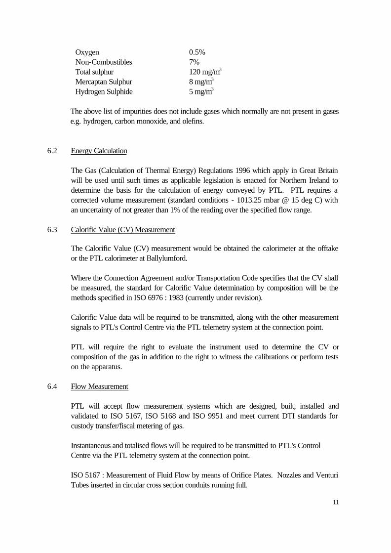
Oxygen 0.5% Non-Combustibles 7% Total sulphur 120 mg/m3 Mercaptan Sulphur 8 mg/m3
Hydrogen Sulphide 5 mg/m3 The above list of impurities does not include gases which normally are not present in gases
e.g. hydrogen, carbon monoxide, and olefins. 6.2 Energy Calculation
The Gas (Calculation of Thermal Energy) Regulations 1996 which apply in Great Britain will be used until such times as applicable legislation is enacted for Northern Ireland to determine the basis for the calculation of energy conveyed by PTL. PTL requires a corrected volume measurement (standard conditions - 1013.25 mbar @ 15 deg C) with an uncertainty of not greater than 1% of the reading over the specified flow range.
6.3 Calorific Value (CV) Measurement
The Calorific Value (CV) measurement would be obtained the calorimeter at the offtake or the PTL calorimeter at Ballylumford. Where the Connection Agreement and/or Transportation Code specifies that the CV shall be measured, the standard for Calorific Value determination by composition will be the methods specified in ISO 6976 : 1983 (currently under revision).
Calorific Value data will be required to be transmitted, along with the other measurement signals to PTL's Control Centre via the PTL telemetry system at the connection point.
PTL will require the right to evaluate the instrument used to determine the CV or composition of the gas in addition to the right to witness the calibrations or perform tests on the apparatus.
6.4 Flow Measurement
PTL will accept flow measurement systems which are designed, built, installed and validated to ISO 5167, ISO 5168 and ISO 9951 and meet current DTI standards for custody transfer/fiscal metering of gas.
Instantaneous and totalised flows will be required to be transmitted to PTL's Control Centre via the PTL telemetry system at the connection point.
ISO 5167 : Measurement of Fluid Flow by means of Orifice Plates. Nozzles and Venturi Tubes inserted in circular cross section conduits running full.

12
ISO 5168 : Measurement of Fluid Flow - Evaluation of Uncertainties
ISO 9951 : Measurement of Gas Flow in closed conduits - Turbine Meters
6.5 Communications Interface The signal type, quality and quantity will need to be discussed to establish the agreed
interface between PTL and the customer. Exchange of information may also be discussed regarding the status of the ROV, alarms, etc. Typical signals required by PTL from the customer's measurement facility are :
-- CV Analogue - Meter outlet pressure (Analogue) - Meter outlet temperature (Analogue) - Relative Density (Analogue) - Instantaneous corrected volume flow (Analogue) - Instantaneous corrected energy flow (Analogue) - Integrated corrected volume flow (Digital) - Integrated corrected energy flow (Digital)
The telemetry system, as well as the range of the signals, will be determined at the detail design stage, and must be compatible with PTL's Control Centre equipment. In addition to the list shown, other signals required by PTL are pressure and temperature signals either side of the hot-tap valve, ROV status and control operation. The telemetry system must be located at the PTL connection, within the secure compound.
6.6 Other Issues to be Agreed by PTL.
Where a customer owns the measurement system, and is therefore responsible for the design, operation and maintenance of this equipment, PTL will require :
a) the right to witness the calibration of the measurement system b) the right to audit and test the measurement system c) that the measurement system installation complies with any OFREG code of
practice. d) evidence regarding the continued certainty of measurement and the maintenance
and calibration and re-calibration procedures. e) predetermined disputes procedures in cases where the uncertainty of measurement
is disputed, etc.

13
The above will be set out in the Connection Agreement (see 'Commercial Arrangements' - Section 8).

14
7. CONNECTION COSTS
When PTL receives an enquiry regarding a new connection from the Network a budget estimate of the connection costs will be provided to the connecting party within 28 days, based on the following:
(i) hot tap, ROV, bypass, insulation joint and associated pipework, C&I equipment (ii) security fence around the connection compound (iii) a prefabricated telemetry kiosk, not a building (iv) minimum lighting (v) no vehicular access inside the compound (vi) all civils and ground works inside the compound (vii) modifications required to the Network control system. (viii) customer provides the land (at nil cost to PTL) for permanent and temporary works
The budget cost information will be based on various assumptions including:
- planning consent (including environmental impact and environmental statement) being undertaken and obtained by the Connecting Party for the PTL installation, customer installation and customer pipeline if applicable.
- no IGE TD1 restrictions - no major underground problems - all utilities available at the connection site during construction and operation - PTL connection work will terminate outside the 'PTL compound' in a dome end
(**)
- there is vehicular access to the connection location
- all based on limited information of the area
(**) the PTL connection will be gassed up to line pressure on the Network side of the ROV valve. This valve will then be validated onto the system upon commissioning of the customers pipeline / measurement facility.

15
A range of indicative costs for each of the items necessary for an offtake is provided in Appendix 3 .
If the customer wishes to pursue the enquiry further, then PTL will prepare a fixed price study, which the customer will pay for. If, in the future, the project goes ahead, then this will form part of the overall final connection charge.
The fixed price package will normally include: - a fixed price (with validity period) and timescales for payment of instalments
- standard drawings of the connection including layouts, line diagrams and materials schedules
- draft Offtake Provision Agreement (OPA) for the connection to the Network
- a draft Connection Agreement between PTL and the Gas User / Connected System Operator
- confirmation of the construction dates and the first Gas date
The standard drawings would not be site specific as these would be prepared at the detail design stage. However, the drawings will indicate the normal installation requirements and layout together with a list of materials required, typical fencing details and C & I equipment layouts. The package will also include an itemised breakdown of the costs that will be discussed with the customer during the presentation of the report.
If the customer wishes to progress the project to the detail design and construction stage, then the customer would sign the Offtake Provision Agreement. The Offtake Provision Agreement and the Connection Agreement can be found in Appendices 1 and 2 respectively.

16
8. COMMERCIAL ARRANGEMENTS
This Section deals mainly with the provision of the physical hardware to enable gas to be offtaken from the Network. Whilst this is a very important process in itself, it cannot stand alone in the overall process of providing transportation arrangements for suppliers.
The overall process, namely to provide Exit Capability, is initiated as an enquiry, developed as a physical connection and concluded by commercial transportation arrangements specific to the Network. Each stage of the process feeds into the next and has to be carefully managed to ensure customer satisfaction and to safeguard PTL's legitimate business interests.
8.1 Construction Stage
Once the conceptual design study has been completed and the fixed price has been accepted, the next stage is to obtain planning consent for the project. This will be done by the Connecting Party although PTL will assist by providing any relevant information as reasonably required by the Consenting Authority. Detailed design and construction of the offtake by PTL will commence only after the signing of the Offtake Provision Agreement (OPA) between PTL and the Connecting Party.
The OPA (See Appendix 2 for table of contents) contains obligations on PTL to design and build the facilities to agreed criteria by a certain date, and obligations on the Connecting Party to reimburse PTL and to provide PTL with timely and accurate information.
It must be made clear that this agreement does not give the customer a right to be tied-in to the Network connection, nor does it give the customer the right to offtake gas, nor does it put PTL under any obligation to reinforce the system. These rights are all obtained by entering into a Connection Agreement and by the Gas Supplier agreeing to gas transportation arrangements through the Transportation Code.
8.2 Transportation Stage
For a new connection to the PTL network, PTL and the operator of the connected facilities must sign a Connection Agreement before the any tie-in between the two parties’ systems can be completed. The Connection Agreement will contain various pieces of site specific information including, maintenance and emergency procedures and also Sections related to technical matters such as pressure, ramp rates, notice periods etc. These technical matters will be dictated by the technical parameters agreed in the OPA, hence the requirement for consistency throughout the project. At existing connections the items normally contained within the Connection Agreement are contained within the Transportation Code. Modifications to existing facilities may require
17
the Transportation Code to be modified, but will not normally require a Connection Agreement. Appendix 2 contains a typical Connection Agreement Any gas transportation may only take place following a nomination by a relevant shipper under the terms of PTL’s Transportation Code. No offtake of gas for any purpose will be permitted before this time.
9. OTHER ARRANGEMENTS
The Connected System Operator will have to agree procedures for interfacing with PTL to support the commercial arrangements. Some of these will form part of the Connection Agreement, whilst others will support other operational and safety areas, e.g. the Connected System Operator will need to develop procedures to be followed in an emergency.

18
APPENDIX 1: DRAFT OFFTAKE PROVISION AGREEMENT

19
APPENDIX 2: CONNECTION AGREEMENT
20
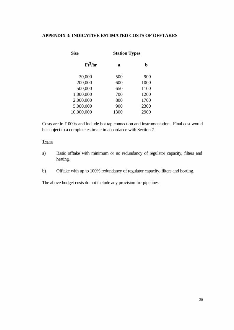
APPENDIX 3: INDICATIVE ESTIMATED COSTS OF OFFTAKES
Size Station Types Ft3/hr a b 30,000 500 900 200,000 600 1000 500,000 650 1100 1,000,000 700 1200 2,000,000 800 1700 5,000,000 900 2300 10,000,000 1300 2900 Costs are in £ 000's and include hot tap connection and instrumentation. Final cost would be subject to a complete estimate in accordance with Section 7. Types a) Basic offtake with minimum or no redundancy of regulator capacity, filters and
heating. b) Offtake with up to 100% redundancy of regulator capacity, filters and heating. The above budget costs do not include any provision for pipelines.

21
Appendix 4
CONNECTIONS PROCESS FLOW DIAGRAM
Offtake parameters to be agreed in Connection Agreement
Is it a new connection or a modification to an existing connection? Offtake parameters
found in Transportation Code
Do you want PTL to carry out all connection work?
Offtake Provisions Agreement required PTL charge cost price. PTL retain ownership of any plant that it builds.
Do you want PTL to carry out any of the work e.g.
Hot tap?
Y
N
N Y
Mod. New
Permission to Work Agreement required. PTL may supervise the Operations
Do you want PTL to take ownership of more than the minimum connection?
Transfer of ownership for minimum connection only
Transfer of ownership for pipeline/meters etc.
N
Y