Premier Instrumentation CR or PS Surgical Technique Vanguard Premier ST.pdf · 3 Vanguard...
36
Premier Instrumentation CR or PS Surgical Technique
Transcript of Premier Instrumentation CR or PS Surgical Technique Vanguard Premier ST.pdf · 3 Vanguard...

Premier Instrumentation CR or PS Surgical Technique

3
Vanguard Premier™ Instrumentation
Introduction
The Vanguard™ Knee System offers the flexibility to change from a cruciate retaining to a posterior stabilized, or posterior stabilized constrained knee within a single system. The transition between each constraint level can be made with ease, allowing the physician to evaluate soft tissue and bone deficiencies intraoperatively without making a preoperative commitment to the level of constraint.
This brochure describes the surgical technique used by Keith R. Berend, M.D.
Biomet does not practice medicine and does not recommend this or any other surgical technique for use on a specific patient. The surgeon who performs
any implant procedure is responsible for determining and using the appropriate
techniques for implanting the prosthesis in each individual patient. Biomet is not responsible for selection of the appropriate products and or surgical
technique(s) to be used on any individual patient.
For product information, including indications, contraindications, warnings, precautions and potential adverse effects, see the package insert herein and
Biomet’s website.
This material is intended for the sole use and benefit of the Biomet sales force and physicians. It is not to be redistributed, duplicated or disclosed without
the express written consent of Biomet.
Microplasty,® Slidex,® Interlok,® Premier,™ Vanguard™ and AGC® are trademarks of Biomet Manufacturing Corp.

4
C.R. & P.S. Surgical Technique
Step 1Premier Technique for Vanguard Knee
Preoperative Planning
In order to assess bone stock, potential ligament instability, and the anatomical axis, a 36" long standing A/P X-ray is recommended. The angle between the anatomic and mechanical axis is determined, assuring the distal femoral cut is perpendicular to the mechanical axis. Femoral component size is estimated preoperatively by using lateral view X-rays and radiographic templates. Lateral view templates are used to approximate the appropriate A/P size femoral component. The appropriate size component is confirmed intraoperatively and is critical for normal kinematics.
5
Vanguard Premier™ Instrumentation
Step 2A
Premier Technique for Vanguard Knee
Intramedullary Adjustable Distal Cut Guide without Handles
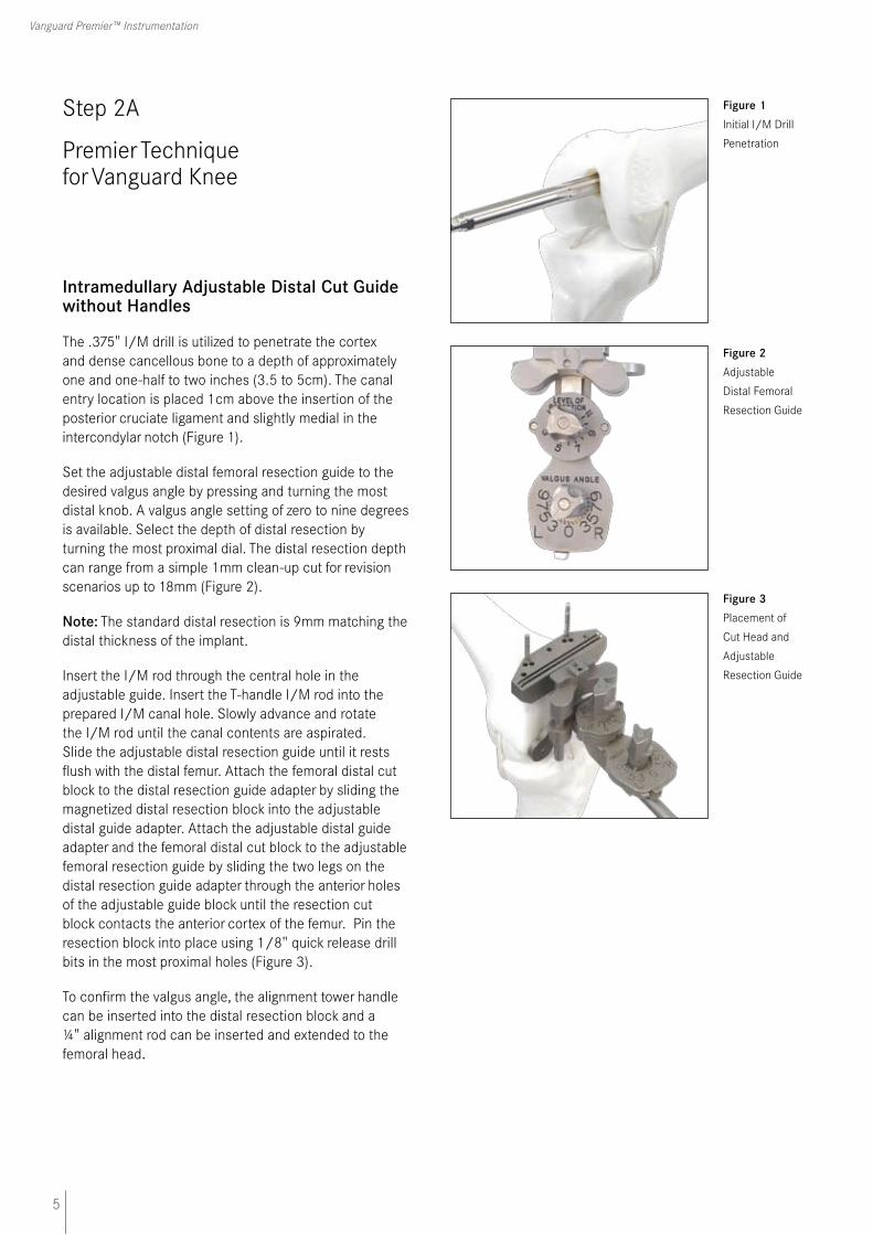
The .375" I/M drill is utilized to penetrate the cortex and dense cancellous bone to a depth of approximately one and one-half to two inches (3.5 to 5cm). The canal entry location is placed 1cm above the insertion of the posterior cruciate ligament and slightly medial in the intercondylar notch (Figure 1).
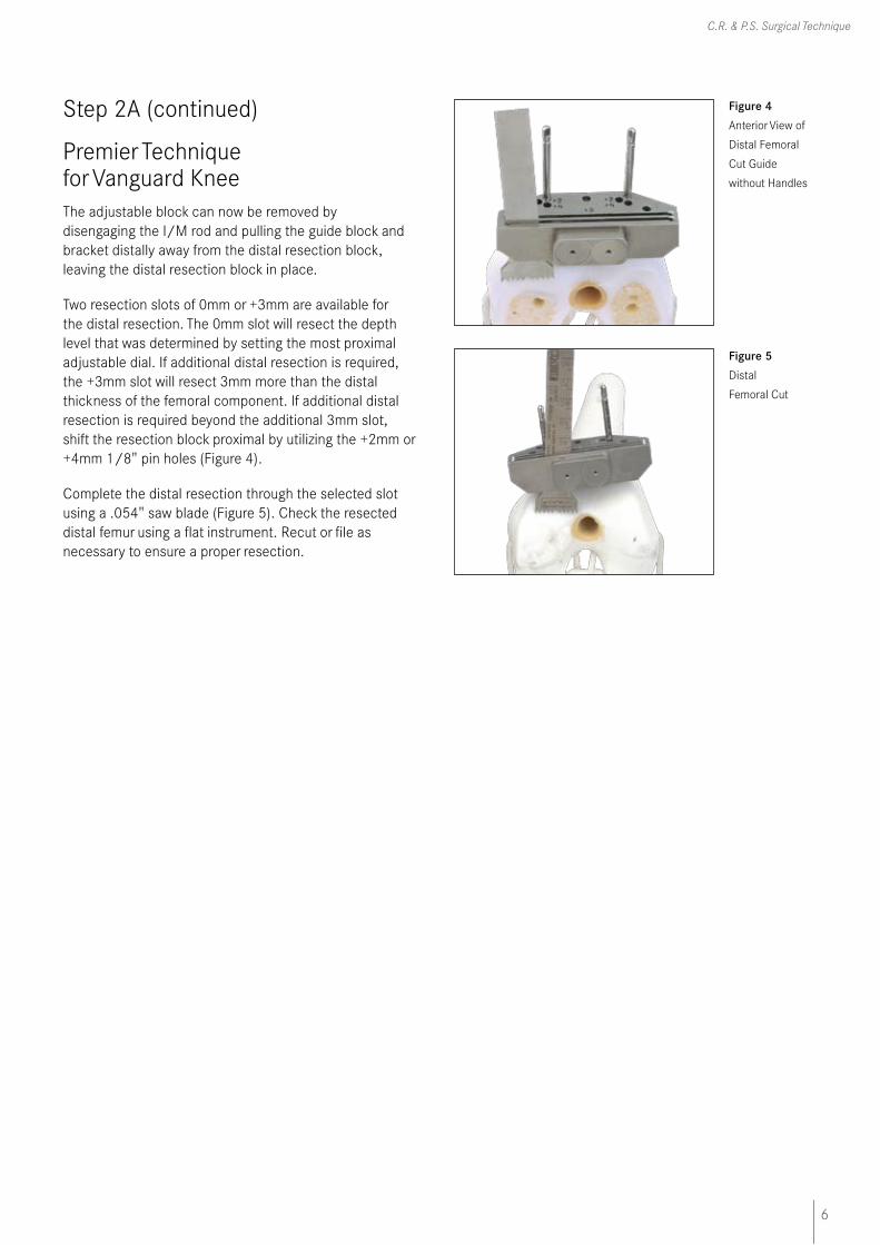
Set the adjustable distal femoral resection guide to the desired valgus angle by pressing and turning the most distal knob. A valgus angle setting of zero to nine degrees is available. Select the depth of distal resection by turning the most proximal dial. The distal resection depth can range from a simple 1mm clean-up cut for revision scenarios up to 18mm (Figure 2).
Note: The standard distal resection is 9mm matching the distal thickness of the implant.
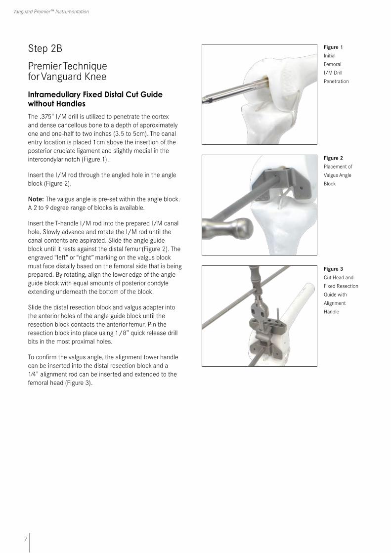
Insert the I/M rod through the central hole in the adjustable guide. Insert the T-handle I/M rod into the prepared I/M canal hole. Slowly advance and rotate the I/M rod until the canal contents are aspirated. Slide the adjustable distal resection guide until it rests flush with the distal femur. Attach the femoral distal cut block to the distal resection guide adapter by sliding the magnetized distal resection block into the adjustable distal guide adapter. Attach the adjustable distal guide adapter and the femoral distal cut block to the adjustable femoral resection guide by sliding the two legs on the distal resection guide adapter through the anterior holes of the adjustable guide block until the resection cut block contacts the anterior cortex of the femur. Pin the resection block into place using 1/8" quick release drill bits in the most proximal holes (Figure 3).
To confirm the valgus angle, the alignment tower handle can be inserted into the distal resection block and a ¼" alignment rod can be inserted and extended to the femoral head.
Figure 1 Initial I/M Drill
Penetration
Figure 2 Adjustable
Distal Femoral
Resection Guide
Figure 3
Placement of
Cut Head and
Adjustable
Resection Guide
6
C.R. & P.S. Surgical Technique
Step 2A (continued)
Premier Technique for Vanguard KneeThe adjustable block can now be removed by disengaging the I/M rod and pulling the guide block and bracket distally away from the distal resection block, leaving the distal resection block in place.
Two resection slots of 0mm or +3mm are available for the distal resection. The 0mm slot will resect the depth level that was determined by setting the most proximal adjustable dial. If additional distal resection is required, the +3mm slot will resect 3mm more than the distal thickness of the femoral component. If additional distal resection is required beyond the additional 3mm slot, shift the resection block proximal by utilizing the +2mm or +4mm 1/8" pin holes (Figure 4).
Complete the distal resection through the selected slot using a .054" saw blade (Figure 5). Check the resected distal femur using a flat instrument. Recut or file as necessary to ensure a proper resection.
Figure 4 Anterior View of
Distal Femoral
Cut Guide
without Handles
Figure 5 Distal
Femoral Cut
7
Vanguard Premier™ Instrumentation
Step 2B
Premier Technique for Vanguard Knee
Intramedullary Fixed Distal Cut Guide without Handles
The .375" I/M drill is utilized to penetrate the cortex and dense cancellous bone to a depth of approximately one and one-half to two inches (3.5 to 5cm). The canal entry location is placed 1cm above the insertion of the posterior cruciate ligament and slightly medial in the intercondylar notch (Figure 1).
Insert the I/M rod through the angled hole in the angle block (Figure 2).
Note: The valgus angle is pre-set within the angle block. A 2 to 9 degree range of blocks is available.
Insert the T-handle I/M rod into the prepared I/M canal hole. Slowly advance and rotate the I/M rod until the canal contents are aspirated. Slide the angle guide block until it rests against the distal femur (Figure 2). The engraved “left” or “right” marking on the valgus block must face distally based on the femoral side that is being prepared. By rotating, align the lower edge of the angle guide block with equal amounts of posterior condyle extending underneath the bottom of the block.
Slide the distal resection block and valgus adapter into the anterior holes of the angle guide block until the resection block contacts the anterior femur. Pin the resection block into place using 1/8" quick release drill bits in the most proximal holes.
To confirm the valgus angle, the alignment tower handle can be inserted into the distal resection block and a 1⁄4" alignment rod can be inserted and extended to the femoral head (Figure 3).
Figure 1 Initial
Femoral
I/M Drill
Penetration
Figure 2 Placement of
Valgus Angle
Block
Figure 3 Cut Head and
Fixed Resection
Guide with
Alignment
Handle

8
C.R. & P.S. Surgical Technique
Step 2B (continued)
Premier Technique for Vanguard Knee
The angle block can now be removed by removing the I/M rod and pulling the angle guide block and bracket distally away from the distal resection block, leaving the distal resection block in place.
Two resection slots of 0mm or +3mm are available for the distal resection. The 0mm slot will resect 9mm from the most prominent condyle. If additional distal resection is required, the +3mm slot will resect 12mm, 3mm more than the distal thickness of the femoral component. If additional distal resection is required beyond the additional 3mm slot, shift the resection block proximal by utilizing the +2mm or +4mm 1/8" pin holes (Figure 4).
Complete the distal resection through the selected slot using a .054" saw blade (Figure 5). Check the resected distal femur using a flat instrument. Recut or file as necessary to ensure a proper resection.
Figure 5 Distal Femoral
Cut
Figure 4 Anterior View of
Distal Femoral
Cut Guide
without Handles
9
Vanguard Premier™ Instrumentation
Step 3A
Premier Technique for Vanguard Knee
Distal Femoral Sizing Slidex® A/P Sizer with Standard Feet
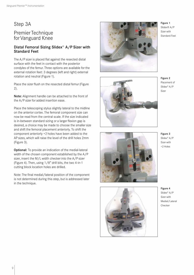
The A/P sizer is placed flat against the resected distal surface with the feet in contact with the posterior condyles of the femur. Three options are available for the external rotation feet: 3 degrees (left and right) external rotation and neutral (Figure 1).
Place the sizer flush on the resected distal femur (Figure 2).
Note: Alignment handle can be attached to the front of the A/P sizer for added insertion ease.
Place the telescoping stylus slightly lateral to the midline on the anterior cortex. The femoral component size can now be read from the central scale. If the size indicated is in-between standard sizing or a larger flexion gap is desired, a choice may be made to choose the smaller size and shift the femoral placement anteriorly. To shift the component anteriorly +2 holes have been added to the AP sizes, which will raise the level of the drill holes 2mm (Figure 3).
Optional: To provide an indication of the medial-lateral width of the chosen component established by the A/P sizer, insert the M/L width checker into the A/P sizer (Figure 4). Then, using 1/8” drill bits, the two 4-in-1 cutting block location holes are drilled.
Note: The final medial/lateral position of the component is not determined during this step, but is addressed later in the technique.
Figure 1
Slidex® A/P
Sizer with
Standard Feet
Figure 2
Placement of
Slidex® A/P
Sizer
Figure 4 Slidex® A/P
Sizer with
Medial/Lateral
Checker
Figure 3 Slidex® A/P
Sizer with
+2 Holes
10
C.R. & P.S. Surgical Technique
Step 3B
Premier Technique for Vanguard Knee
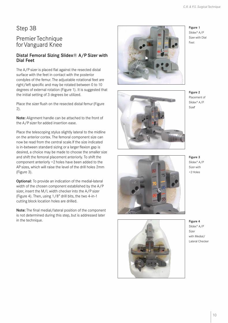
Distal Femoral Sizing Slidex® A/P Sizer with Dial Feet
The A/P sizer is placed flat against the resected distal surface with the feet in contact with the posterior condyles of the femur. The adjustable rotational feet are right/left specific and may be rotated between 0 to 10 degrees of external rotation (Figure 1). It is suggested that the initial setting of 3 degrees be utilized.
Place the sizer flush on the resected distal femur (Figure 2).
Note: Alignment handle can be attached to the front of the A/P sizer for added insertion ease.
Place the telescoping stylus slightly lateral to the midline on the anterior cortex. The femoral component size can now be read from the central scale.If the size indicated is in-between standard sizing or a larger flexion gap is desired, a choice may be made to choose the smaller size and shift the femoral placement anteriorly. To shift the component anteriorly +2 holes have been added to the AP sizes, which will raise the level of the drill holes 2mm (Figure 3).
Optional: To provide an indication of the medial-lateral width of the chosen component established by the A/P sizer, insert the M/L width checker into the A/P sizer (Figure 4). Then, using 1/8” drill bits, the two 4-in-1 cutting block location holes are drilled.
Note: The final medial/lateral position of the component is not determined during this step, but is addressed later in the technique.
Figure 1 Slidex® A/P
Sizer with Dial
Feet
Figure 2 Placement of
Slidex® A/P
Sizer
Figure 4 Slidex® A/P
Sizer
with Medial/
Lateral Checker
Figure 3 Slidex® A/P
Sizer with
+2 Holes

11
Vanguard Premier™ Instrumentation
Step 3C
Premier Technique for Vanguard Knee
Adjustable Distal Femoral A/P Sizer with Standard Feet
The adjustable A/P sizer is placed flat against the resected distal surface with the feet in contact with the posterior condyles of the femur. Three options are available for the external rotation feet: 3° (left and right) external rotation and neutral (Figure 1).
Place the sizer flush on the resected distal femur. Place the telescoping stylus slightly lateral to the midline on the anterior cortex. The femoral component size can now be read from the central scale. If the size indicated is in-between standard sizing or a larger flexion gap is desired, a choice may be made to choose the smaller size and shift the femoral placement anteriorly. To shift the component anteriorly, turn the screw mechanism in the central portion of the sizer, which will in turn raise the level of drill holes in 1mm increments (Figure 2). A scale is located on the sizer to indicate how far the component will be anteriorly shifted.
Optional: To provide an indication of the medial-lateral width of the chosen component established by the A/P sizer, insert the M/L width checker into the A/P sizer (Figure 3). Then, using 1/8” drill bits, the two 4-in-1 cutting block location holes are drilled (Figure 3).
Then, using 1/8" drill bits, the two 4-in-1 cutting block location holes are drilled (Figure 4).
Note: The final medial/lateral position of the component is not determined during this step, but is addressed later in the technique.
Figure 1 Adjustable A/P
Sizer with
Standard Feet
Figure 2 Placement of
Adjustable
A/P Sizer
with Screw
Mechanism
Engaged
Figure 3 Adjustable A/P
Sizer
with Medial/
Lateral Checker
Figure 4 Final Position of
Adjustable A/P
Sizer
12
C.R. & P.S. Surgical Technique
Step 3D
Premier Technique for Vanguard Knee
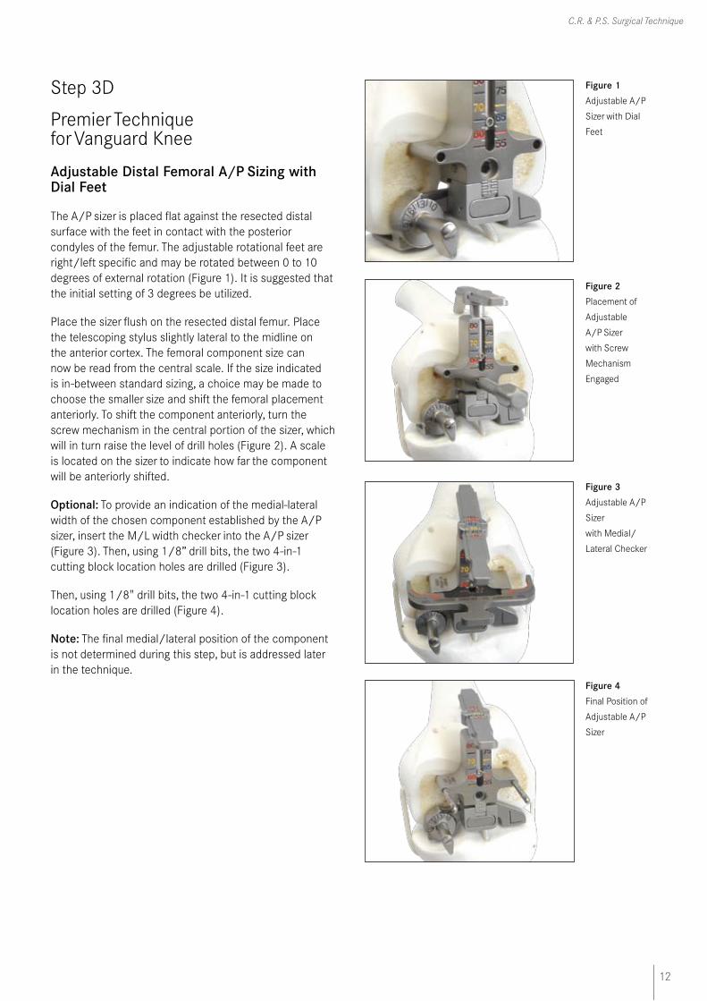
Adjustable Distal Femoral A/P Sizing with Dial Feet
The A/P sizer is placed flat against the resected distal surface with the feet in contact with the posterior condyles of the femur. The adjustable rotational feet are right/left specific and may be rotated between 0 to 10 degrees of external rotation (Figure 1). It is suggested that the initial setting of 3 degrees be utilized.
Place the sizer flush on the resected distal femur. Place the telescoping stylus slightly lateral to the midline on the anterior cortex. The femoral component size can now be read from the central scale. If the size indicated is in-between standard sizing, a choice may be made to choose the smaller size and shift the femoral placement anteriorly. To shift the component anteriorly, turn the screw mechanism in the central portion of the sizer, which will in turn raise the level of drill holes (Figure 2). A scale is located on the sizer to indicate how far the component will be anteriorly shifted.
Optional: To provide an indication of the medial-lateral width of the chosen component established by the A/P sizer, insert the M/L width checker into the A/P sizer (Figure 3). Then, using 1/8” drill bits, the two 4-in-1 cutting block location holes are drilled (Figure 3).
Then, using 1/8" drill bits, the two 4-in-1 cutting block location holes are drilled (Figure 4).
Note: The final medial/lateral position of the component is not determined during this step, but is addressed later in the technique.
Figure 1 Adjustable A/P
Sizer with Dial
Feet
Figure 2 Placement of
Adjustable
A/P Sizer
with Screw
Mechanism
Engaged
Figure 3 Adjustable A/P
Sizer
with Medial/
Lateral Checker
Figure 4 Final Position of
Adjustable A/P
Sizer
13
Vanguard Premier™ Instrumentation
Step 4
Premier Technique for Vanguard Knee
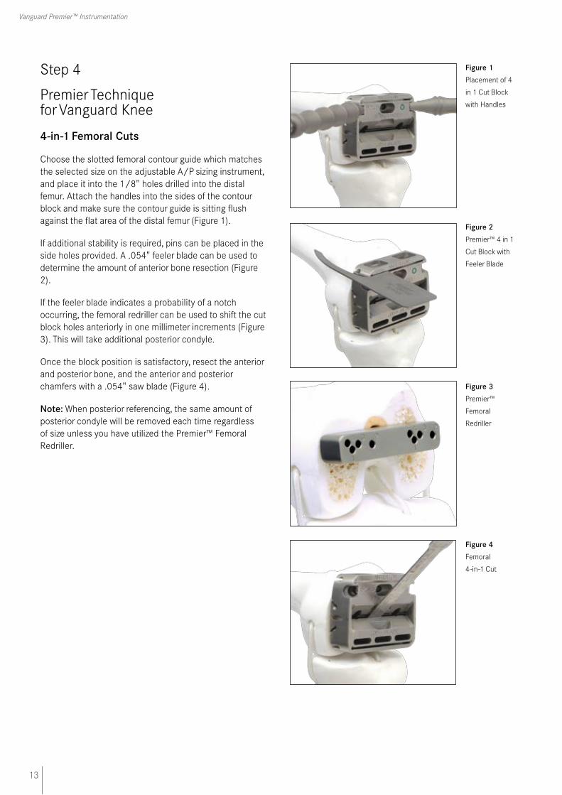
4-in-1 Femoral Cuts
Choose the slotted femoral contour guide which matches the selected size on the adjustable A/P sizing instrument, and place it into the 1/8" holes drilled into the distal femur. Attach the handles into the sides of the contour block and make sure the contour guide is sitting flush against the flat area of the distal femur (Figure 1).
If additional stability is required, pins can be placed in the side holes provided. A .054" feeler blade can be used to determine the amount of anterior bone resection (Figure 2).
If the feeler blade indicates a probability of a notch occurring, the femoral redriller can be used to shift the cut block holes anteriorly in one millimeter increments (Figure 3). This will take additional posterior condyle.
Once the block position is satisfactory, resect the anterior and posterior bone, and the anterior and posterior chamfers with a .054" saw blade (Figure 4).
Note: When posterior referencing, the same amount of posterior condyle will be removed each time regardless of size unless you have utilized the Premier™ Femoral Redriller.
Figure 1 Placement of 4
in 1 Cut Block
with Handles
Figure 2 Premier™ 4 in 1
Cut Block with
Feeler Blade
Figure 3 Premier™
Femoral
Redriller
Figure 4 Femoral
4-in-1 Cut
14
C.R. & P.S. Surgical Technique
Step 5A
Premier Technique for Vanguard Knee
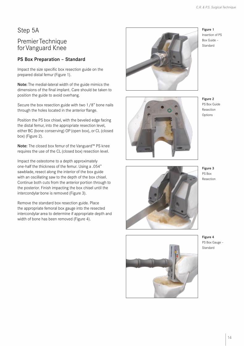
PS Box Preparation – Standard
Impact the size specific box resection guide on the prepared distal femur (Figure 1).
Note: The medial-lateral width of the guide mimics the dimensions of the final implant. Care should be taken to position the guide to avoid overhang.
Secure the box resection guide with two 1/8" bone nails through the holes located in the anterior flange.
Position the PS box chisel, with the beveled edge facing the distal femur, into the appropriate resection level, either BC (bone conserving) OP (open box), or CL (closed box) (Figure 2).
Note: The closed box femur of the Vanguard™ PS knee requires the use of the CL (closed box) resection level.
Impact the osteotome to a depth approximately one-half the thickness of the femur. Using a .054" sawblade, resect along the interior of the box guide with an oscillating saw to the depth of the box chisel. Continue both cuts from the anterior portion through to the posterior. Finish impacting the box chisel until the intercondylar bone is removed (Figure 3).
Remove the standard box resection guide. Place the appropriate femoral box gauge into the resected intercondylar area to determine if appropriate depth and width of bone has been removed (Figure 4).
Figure 1 Insertion of PS
Box Guide –
Standard
Figure 2 PS Box Guide
Resection
Options
Figure 3 PS Box
Resection
Figure 4 PS Box Gauge –
Standard
15
Vanguard Premier™ Instrumentation
Step 6A
Premier Technique for Vanguard Knee
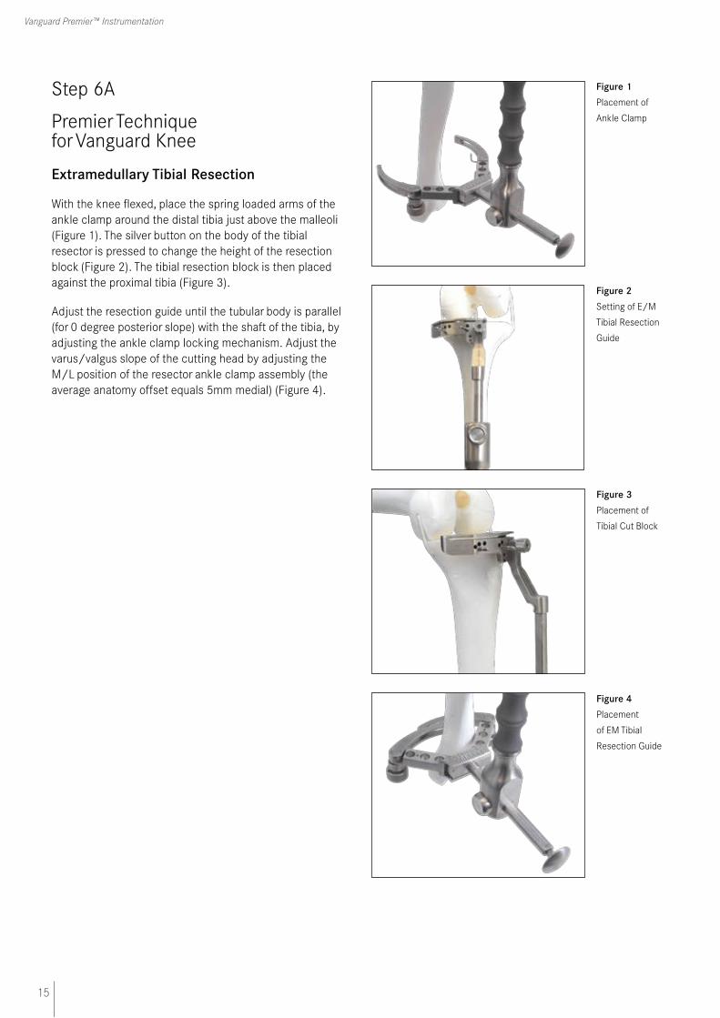
Extramedullary Tibial Resection
With the knee flexed, place the spring loaded arms of the ankle clamp around the distal tibia just above the malleoli (Figure 1). The silver button on the body of the tibial resector is pressed to change the height of the resection block (Figure 2). The tibial resection block is then placed against the proximal tibia (Figure 3).
Adjust the resection guide until the tubular body is parallel (for 0 degree posterior slope) with the shaft of the tibia, by adjusting the ankle clamp locking mechanism. Adjust the varus/valgus slope of the cutting head by adjusting the M/L position of the resector ankle clamp assembly (the average anatomy offset equals 5mm medial) (Figure 4).
Figure 1 Placement of
Ankle Clamp
Figure 2 Setting of E/M
Tibial Resection
Guide
Figure 3 Placement of
Tibial Cut Block
Figure 4 Placement
of EM Tibial
Resection Guide
16
C.R. & P.S. Surgical Technique
Step 6A (continued)
Premier Technique for Vanguard Knee
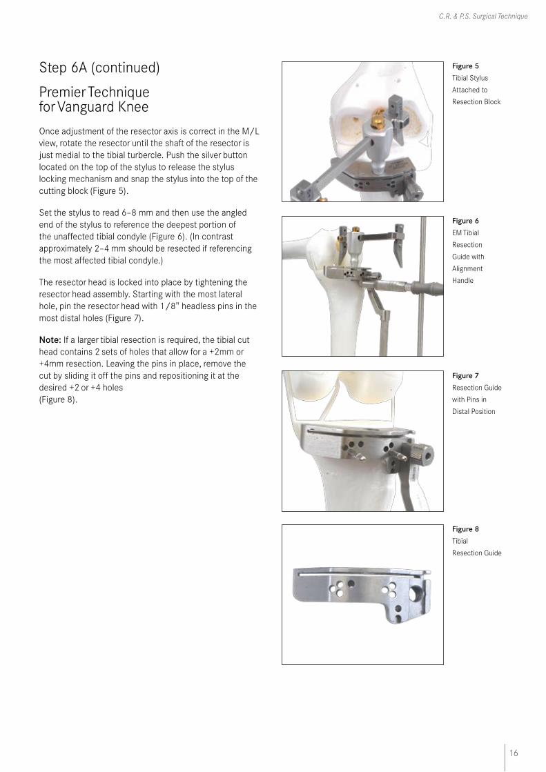
Once adjustment of the resector axis is correct in the M/L view, rotate the resector until the shaft of the resector is just medial to the tibial turbercle. Push the silver button located on the top of the stylus to release the stylus locking mechanism and snap the stylus into the top of the cutting block (Figure 5).
Set the stylus to read 6–8 mm and then use the angled end of the stylus to reference the deepest portion of the unaffected tibial condyle (Figure 6). (In contrast approximately 2–4 mm should be resected if referencing the most affected tibial condyle.)
The resector head is locked into place by tightening the resector head assembly. Starting with the most lateral hole, pin the resector head with 1/8" headless pins in the most distal holes (Figure 7).
Note: If a larger tibial resection is required, the tibial cut head contains 2 sets of holes that allow for a +2mm or +4mm resection. Leaving the pins in place, remove the cut by sliding it off the pins and repositioning it at the desired +2 or +4 holes (Figure 8).
Figure 6 EM Tibial
Resection
Guide with
Alignment
Handle
Figure 5 Tibial Stylus
Attached to
Resection Block
Figure 7 Resection Guide
with Pins in
Distal Position
Figure 8 Tibial
Resection Guide
17
Vanguard Premier™ Instrumentation
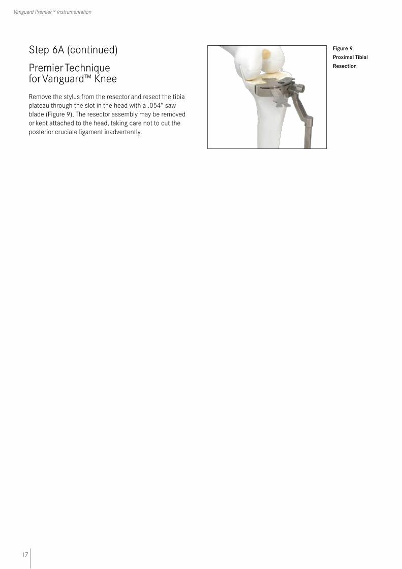
Figure 9 Proximal Tibial
Resection
Step 6A (continued)
Premier Technique for Vanguard™ Knee
Remove the stylus from the resector and resect the tibia plateau through the slot in the head with a .054" saw blade (Figure 9). The resector assembly may be removed or kept attached to the head, taking care not to cut the posterior cruciate ligament inadvertently.
18
C.R. & P.S. Surgical Technique
Step 6B
Premier Technique for Vanguard Knee
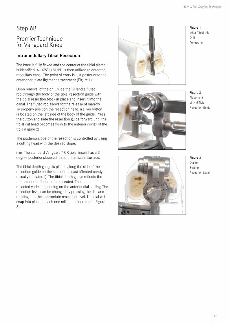
Intramedullary Tibial Resection
The knee is fully flexed and the center of the tibial plateau is identified. A .375" I/M drill is then utilized to enter the medullary canal. The point of entry is just posterior to the anterior cruciate ligament attachment (Figure 1).
Upon removal of the drill, slide the T-Handle fluted rod through the body of the tibial resection guide with the tibial resection block in place and insert it into the canal. The fluted rod allows for the release of marrow. To properly position the resection head, a silver button is located on the left side of the body of the guide. Press the button and slide the resection guide forward until the tibial cut head becomes flush to the anterior cortex of the tibia (Figure 2).
The posterior slope of the resection is controlled by using a cutting head with the desired slope.
Note: The standard Vanguard™ CR tibial insert has a 3 degree posterior slope built into the articular surface.
The tibial depth gauge is placed along the side of the resection guide on the side of the least affected condyle (usually the lateral). The tibial depth gauge reflects the total amount of bone to be resected. The amount of bone resected varies depending on the anterior dial setting. The resection level can be changed by pressing the dial and rotating it to the appropriate resection level. The dial will snap into place at each one millimeter increment (Figure 3).
Figure 1 Initial Tibial I/M
Drill
Penetration
Figure 2 Placement
of I/M Tibial
Resection Guide
Figure 3 Dial for
Setting
Resection Level
19
Vanguard Premier™ Instrumentation
Step 6B (continued)
Premier Technique for Vanguard Knee
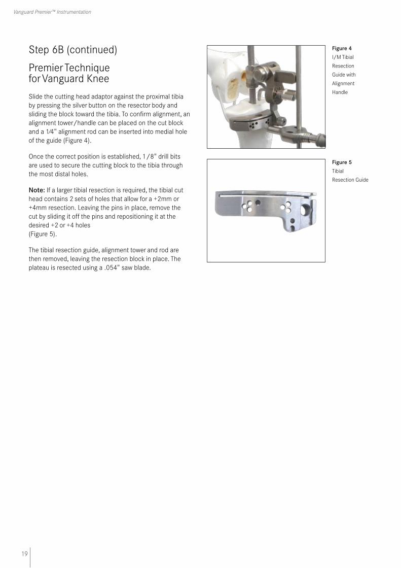
Slide the cutting head adaptor against the proximal tibia by pressing the silver button on the resector body and sliding the block toward the tibia. To confirm alignment, an alignment tower/handle can be placed on the cut block and a 1⁄4" alignment rod can be inserted into medial hole of the guide (Figure 4).
Once the correct position is established, 1/8" drill bits are used to secure the cutting block to the tibia through the most distal holes.
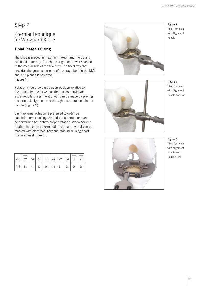
Note: If a larger tibial resection is required, the tibial cut head contains 2 sets of holes that allow for a +2mm or +4mm resection. Leaving the pins in place, remove the cut by sliding it off the pins and repositioning it at the desired +2 or +4 holes (Figure 5).
The tibial resection guide, alignment tower and rod are then removed, leaving the resection block in place. The plateau is resected using a .054" saw blade.
Figure 4 I/M Tibial
Resection
Guide with
Alignment
Handle
Figure 5 Tibial
Resection Guide
20
C.R. & P.S. Surgical Technique
Step 7
Premier Technique for Vanguard Knee
Tibial Plateau Sizing
The knee is placed in maximum flexion and the tibia is subluxed anteriorly. Attach the alignment tower/handle to the medial side of the trial tray. The tibial tray that provides the greatest amount of coverage both in the M/L and A/P planes is selected (Figure 1).
Rotation should be based upon position relative to the tibial tubercle as well as the malleolar axis. An extramedullary alignment check can be made by placing the external alignment rod through the lateral hole in the handle (Figure 2).
Slight external rotation is preferred to optimize patellofemoral tracking. An initial trial reduction can be performed to confirm proper rotation. When correct rotation has been determined, the tibial tray trial can be marked with electrocautery and stabilized using short fixation pins (Figure 3).
Micro Macro Macro
M/L 59 63 67 71 75 79 83 87 91
A/P 38 41 43 46 48 51 53 56 58
Figure 1 Tibial Template
with Alignment
Handle
Figure 2 Tibial Template
with Alignment
Handle and Rod
Figure 3 Tibial Template
with Alignment
Handle and
Fixation Pins

21
Vanguard Premier™ Instrumentation
Step 8A
Premier Technique for Vanguard Knee
Tibial Stem-Punch Guide/Trial I-Beam Cement
The punch guide is assembled to the tibial template utilizing the quick release lock (Figure 1). The starter reamer is introduced to provide an initial hole into the tibia before the selected stem punch is used (Figure 2). The starter reamer should be fully engaged in the punch guide before power in started.
Note: To assemble the tibial punch, choose the appropriate tibial stem punch head. Attach the punch head by pressing the button on the top of the handle (Figure 3).
Carefully drive the I-Beam cement punch into the punch guide until it mechanically stops (a mechanical stop is designed to provide the correct punching depth) (Figure 4).
Figure 1 Tibial Punch
Guide
Figure 2 Starter Reamer
with Tibial
Punch Guide
Figure 3 Punch
Handle with
I-Beam Head
Attached
Figure 4 I-Beam
Cement Punch
with Tibial
Punch Guide
Inset Shows
Top View
of Punch
Handle

22
C.R. & P.S. Surgical Technique
Step 8A (continued)
Premier Technique for Vanguard Knee
Figure 5 Tibial Tray Trial
with Stem
After the punch is fully seated press the button on top of the punch handle to release the punch head. The punch head sits in the tibial trial plate and acts as the trial stem (Figure 5).
23
Vanguard Premier™ Instrumentation
Step 8B
Premier Technique for Vanguard Knee
Tibial Stem-Punch Guide/Trial I-Beam without Cement
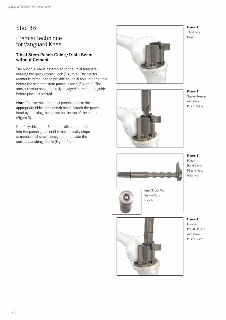
The punch guide is assembled to the tibial template utilizing the quick release lock (Figure 1). The starter reamer is introduced to provide an initial hole into the tibia before the selected stem punch is used (Figure 2). The starter reamer should be fully engaged in the punch guide before power is started.
Note: To assemble the tibial punch, choose the appropriate tibial stem punch head. Attach the punch head by pressing the button on the top of the handle (Figure 3).
Carefully drive the I-Beam pressfit stem punch into the punch guide until it mechanically stops (a mechanical stop is designed to provide the correct punching depth) (Figure 4).
Figure 1 Tibial Punch
Guide
Figure 2 Starter Reamer
with Tibial
Punch Guide
Figure 4 I-Beam
Pressfit Punch
with Tibial
Punch Guide
Figure 3 Punch
Handle with
I-Beam Head
Attached
Inset Shows Top
View of Punch
Handle

24
C.R. & P.S. Surgical Technique
Step 8B (continued)
Premier Technique for Vanguard Knee
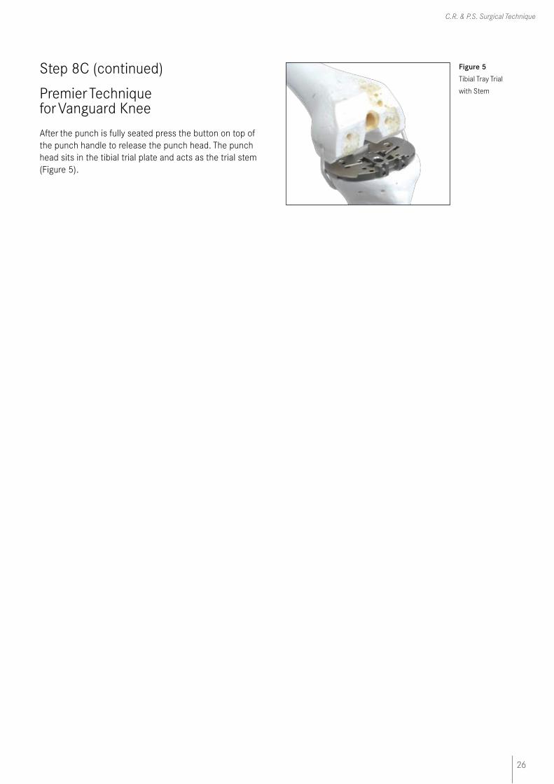
Figure 5 Tibial Tray Trial
with Stem
After the punch is fully seated press the button on top of the punch handle to release the punch head. The punch head sits in the tibial trial plate and acts as the trial stem (Figure 5).

25
Vanguard Premier™ Instrumentation
Step 8C
Premier Technique for Vanguard Knee
Tibial Stem-Punch Guide/Trial Finned Stem
The punch guide is assembled to the tibial template utilizing the quick release lock (Figure 1).
The starter reamer should not be used when preparing for insertion of the Biomet® CoCr finned tray. In this case, only the finned stem punch should be used (Figure 2).
Note: To assemble the tibial punch, choose the appropriate tibial stem punch head. Attach the punch head by pressing the button on the top of the handle (Figure 3).
Carefully drive the Cruciate Finned stem punch into the punch guide until it mechanically stops (a mechanical stop is designed to provide the correct punching depth) (Figure 4).
Figure 1 Tibial Punch
Guide
Figure 4 Cruciate Fin
Punch
with Tibial
Punch Guide
Figure 3 Punch
Handle with
Cruciate Fin
Head
Attached
Figure 2 Starter Reamer
with Tibial
Punch Guide
Inset Shows
Top View
of Punch
Handle
26
C.R. & P.S. Surgical Technique
Step 8C (continued)
Premier Technique for Vanguard Knee
Figure 5 Tibial Tray Trial
with Stem
After the punch is fully seated press the button on top of the punch handle to release the punch head. The punch head sits in the tibial trial plate and acts as the trial stem (Figure 5).
27
Vanguard Premier™ Instrumentation
Step 9A
Premier Technique for Vanguard Knee
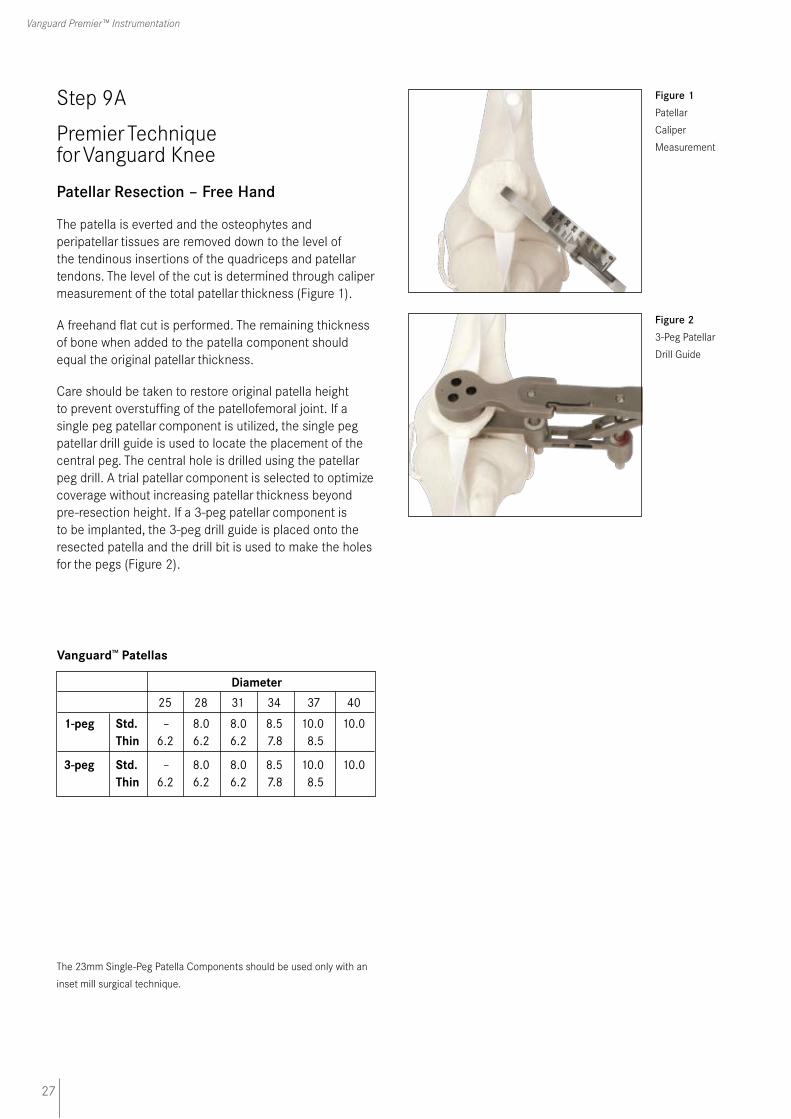
Patellar Resection – Free Hand
The patella is everted and the osteophytes and peripatellar tissues are removed down to the level of the tendinous insertions of the quadriceps and patellar tendons. The level of the cut is determined through caliper measurement of the total patellar thickness (Figure 1).
A freehand flat cut is performed. The remaining thickness of bone when added to the patella component should equal the original patellar thickness.
Care should be taken to restore original patella height to prevent overstuffing of the patellofemoral joint. If a single peg patellar component is utilized, the single peg patellar drill guide is used to locate the placement of the central peg. The central hole is drilled using the patellar peg drill. A trial patellar component is selected to optimize coverage without increasing patellar thickness beyond pre-resection height. If a 3-peg patellar component is to be implanted, the 3-peg drill guide is placed onto the resected patella and the drill bit is used to make the holes for the pegs (Figure 2).
Vanguard™ Patellas
Diameter 25 28 31 34 37 40
1-peg Std. – 8.0 8.0 8.5 10.0 10.0 Thin 6.2 6.2 6.2 7.8 8.5
3-peg Std. – 8.0 8.0 8.5 10.0 10.0 Thin 6.2 6.2 6.2 7.8 8.5
Figure 1 Patellar
Caliper
Measurement
Figure 2 3-Peg Patellar
Drill Guide
The 23mm Single-Peg Patella Components should be used only with an
inset mill surgical technique.
28
C.R. & P.S. Surgical Technique
Step 9B
Premier Technique for Vanguard Knee
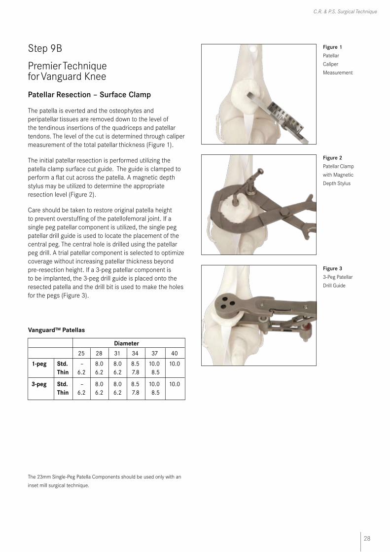
Patellar Resection – Surface Clamp
The patella is everted and the osteophytes and peripatellar tissues are removed down to the level of the tendinous insertions of the quadriceps and patellar tendons. The level of the cut is determined through caliper measurement of the total patellar thickness (Figure 1).
The initial patellar resection is performed utilizing the patella clamp surface cut guide. The guide is clamped to perform a flat cut across the patella. A magnetic depth stylus may be utilized to determine the appropriate resection level (Figure 2).
Care should be taken to restore original patella height to prevent overstuffing of the patellofemoral joint. If a single peg patellar component is utilized, the single peg patellar drill guide is used to locate the placement of the central peg. The central hole is drilled using the patellar peg drill. A trial patellar component is selected to optimize coverage without increasing patellar thickness beyond pre-resection height. If a 3-peg patellar component is to be implanted, the 3-peg drill guide is placed onto the resected patella and the drill bit is used to make the holes for the pegs (Figure 3).
Vanguard™ Patellas
Diameter 25 28 31 34 37 40
1-peg Std. – 8.0 8.0 8.5 10.0 10.0 Thin 6.2 6.2 6.2 7.8 8.5
3-peg Std. – 8.0 8.0 8.5 10.0 10.0 Thin 6.2 6.2 6.2 7.8 8.5
Figure 1 Patellar
Caliper
Measurement
Figure 2 Patellar Clamp
with Magnetic
Depth Stylus
Figure 3 3-Peg Patellar
Drill Guide
The 23mm Single-Peg Patella Components should be used only with an
inset mill surgical technique.

29
Vanguard Premier™ Instrumentation
Step 10A
Premier Technique for Vanguard Knee
CR Trial Reduction
With all bony surfaces prepared and soft tissue debrided, a trial reduction may be completed with the trial components. The trial femoral component is placed on the distal femur with the femoral inserter and initially impacted. Fully seat the femoral trial with the final femoral impactor (Figure 1).
Place the trial tibial plate with corresponding stem onto the tibial plateau. Trial bearing inserts are then sequential-ly selected to determine the appropriate thickness of tibial component. Select the appropriate trial patellar compo-nent and place onto the patella. With the trial components in place, check the range-of-motion and stability of the knee (Figure 2). If tightness is found medial/laterally, in flexion, or in extension, appropriate soft tissue releases may be performed.
Placement of the Femoral Component
With the trial femoral, trial tibial bearing, and baseplate in place, determine the final M/L placement of the cruciate retaining femoral component. Place the patella back into its normal anatomic position (with the trial patella button if used). Manipulate the knee through a normal range-of-motion, observing and noting the tracking and tension of the patellofemoral joint. If necessary, evert the patella and move the femoral component either laterally or medially to improve patella tracking. Replace the patella and repeat the range-of-motion exercise. Repeat as necessary until the patella tracks satisfactorily.
Evert the patella and drill 1⁄4" diameter holes through the holes in the distal condyles of the CR femoral trial (Figure 3).
Figure 1 Initial
Placement of
CR
Femoral Trial
Figure 2 Complete CR
Trials in Place
Figure 3 Final Medial/
Lateral Femoral
Preparation with
1/4" Drill Bit
30
C.R. & P.S. Surgical Technique
Step 10B
Premier Technique for Vanguard Knee
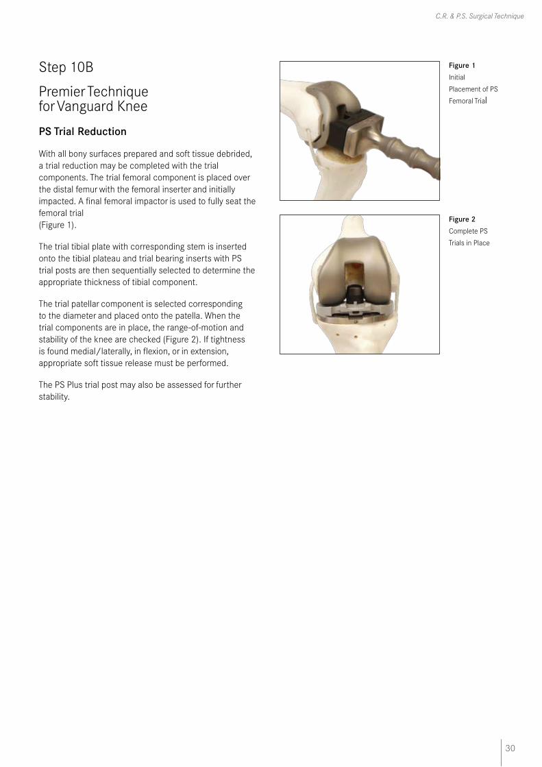
PS Trial Reduction
With all bony surfaces prepared and soft tissue debrided, a trial reduction may be completed with the trial components. The trial femoral component is placed over the distal femur with the femoral inserter and initially impacted. A final femoral impactor is used to fully seat the femoral trial (Figure 1).
The trial tibial plate with corresponding stem is inserted onto the tibial plateau and trial bearing inserts with PS trial posts are then sequentially selected to determine the appropriate thickness of tibial component.
The trial patellar component is selected corresponding to the diameter and placed onto the patella. When the trial components are in place, the range-of-motion and stability of the knee are checked (Figure 2). If tightness is found medial/laterally, in flexion, or in extension, appropriate soft tissue release must be performed.
The PS Plus trial post may also be assessed for further stability.
Figure 1 Initial
Placement of PS
Femoral Trial
Figure 2 Complete PS
Trials in Place
31
Vanguard Premier™ Instrumentation
Step 11
Premier Technique for Vanguard Knee
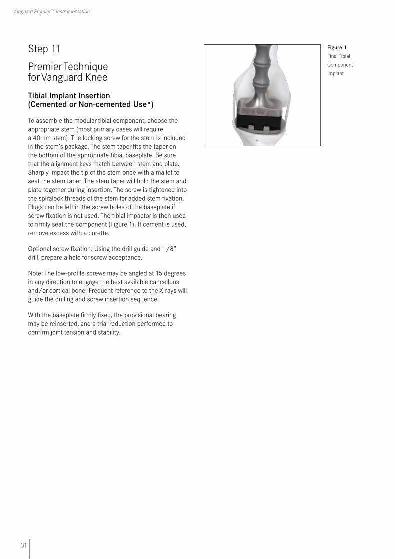
Tibial Implant Insertion (Cemented or Non-cemented Use*)
To assemble the modular tibial component, choose the appropriate stem (most primary cases will require a 40mm stem). The locking screw for the stem is included in the stem’s package. The stem taper fits the taper on the bottom of the appropriate tibial baseplate. Be sure that the alignment keys match between stem and plate. Sharply impact the tip of the stem once with a mallet to seat the stem taper. The stem taper will hold the stem and plate together during insertion. The screw is tightened into the spiralock threads of the stem for added stem fixation. Plugs can be left in the screw holes of the baseplate if screw fixation is not used. The tibial impactor is then used to firmly seat the component (Figure 1). If cement is used, remove excess with a curette.
Optional screw fixation: Using the drill guide and 1/8" drill, prepare a hole for screw acceptance.
Note: The low-profile screws may be angled at 15 degrees in any direction to engage the best available cancellous and/or cortical bone. Frequent reference to the X-rays will guide the drilling and screw insertion sequence.
With the baseplate firmly fixed, the provisional bearing may be reinserted, and a trial reduction performed to confirm joint tension and stability.
Figure 1 Final Tibial
Component
Implant
32
C.R. & P.S. Surgical Technique
Step 12A
Premier Technique for Vanguard Knee
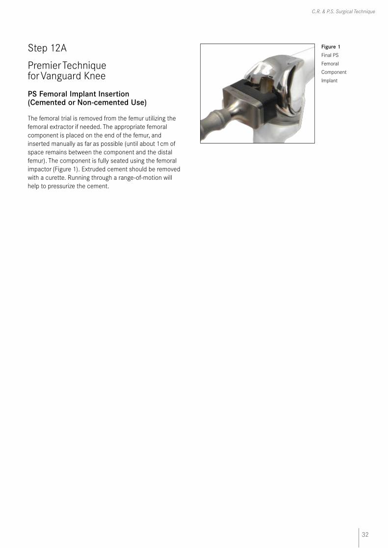
PS Femoral Implant Insertion (Cemented or Non-cemented Use)
The femoral trial is removed from the femur utilizing the femoral extractor if needed. The appropriate femoral component is placed on the end of the femur, and inserted manually as far as possible (until about 1cm of space remains between the component and the distal femur). The component is fully seated using the femoral impactor (Figure 1). Extruded cement should be removed with a curette. Running through a range-of-motion will help to pressurize the cement.
Figure 1 Final PS
Femoral
Component
Implant

33
Vanguard Premier™ Instrumentation
Step 12B
Premier Technique for Vanguard Knee
CR Femoral Implant Insertion (Cemented or Non-cemented Use*)
The femoral trial is removed from the femur utilizing the femoral extractor if needed. The appropriate femoral component is placed on the end of the femur, and inserted manually as far as possible (until about 1cm of space remains between the component and the distal femur). The component is fully seated using the femoral impactor (Figure 1). If cement is used, remove excess with a curette. Running through a range-of-motion will help to pressurize the cement.
*Femoral components and tibial tray components with porous coating are
indicated for cemented and non-cemented biological fixation application.
Figure 1 Final CR
Femoral
Component
Implant
34
C.R. & P.S. Surgical Technique
Step 13
Premier Technique for Vanguard Knee
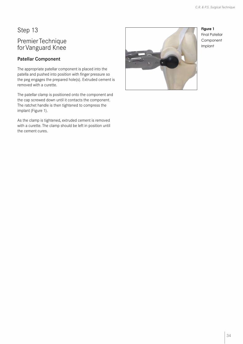
Patellar Component
The appropriate patellar component is placed into the patella and pushed into position with finger pressure so the peg engages the prepared hole(s). Extruded cement is removed with a curette.
The patellar clamp is positioned onto the component and the cap screwed down until it contacts the component. The ratchet handle is then tightened to compress the implant (Figure 1).
As the clamp is tightened, extruded cement is removed with a curette. The clamp should be left in position until the cement cures.
Figure 1
Final Patellar
Component
Implant

35
Vanguard Premier™ Instrumentation
Step 14A
Premier Technique for Vanguard Knee
PS Locking Bar Insertion/Removal
Place the appropriate polyethylene bearing insert on the tibial baseplate and push posteriorly as far as possible using finger pressure. The polyethylene bearing must be flat on the baseplate in all directions. The locking bar, packaged with the tibial baseplate, is inserted into the medial side of the anterior tibial baseplate/polyethylene interface as far as possible using finger pressure (Figure 1). The locking bar must be tight upon insertion. The bar should be too tight to insert with finger pressure only.
The large curved end of the locking bar insertion forceps is placed in the notch on the locking bar. The smaller square end is placed in the notch of the anterior post of the tibial baseplate. Make sure the smaller square end catches on the post of the tibial tray and does not block the path of the locking bar. The forceps will gradually push the locking bar until it clicks into place (Figure 2). A visual and audible confirmation should be made to ensure complete locking bar insertion.
Figure 1 PS
Components
with Locking Bar
Figure 2 Final Locking
Bar Insertion
36
C.R. & P.S. Surgical Technique
Step 14B
Premier Technique for Vanguard Knee
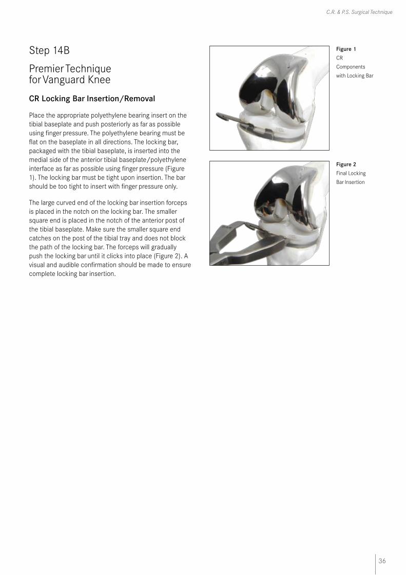
CR Locking Bar Insertion/Removal
Place the appropriate polyethylene bearing insert on the tibial baseplate and push posteriorly as far as possible using finger pressure. The polyethylene bearing must be flat on the baseplate in all directions. The locking bar, packaged with the tibial baseplate, is inserted into the medial side of the anterior tibial baseplate/polyethylene interface as far as possible using finger pressure (Figure 1). The locking bar must be tight upon insertion. The bar should be too tight to insert with finger pressure only.
The large curved end of the locking bar insertion forceps is placed in the notch on the locking bar. The smaller square end is placed in the notch of the anterior post of the tibial baseplate. Make sure the smaller square end catches on the post of the tibial tray and does not block the path of the locking bar. The forceps will gradually push the locking bar until it clicks into place (Figure 2). A visual and audible confirmation should be made to ensure complete locking bar insertion.
Figure 1 CR
Components
with Locking Bar
Figure 2 Final Locking
Bar Insertion
Biomet UK Ltd
Waterton Industrial Estate
Bridgend, South Wales
CF31 3XA, United Kingdom
Tel. 01656 655221Fax: 01656 645454
FLK1
67
02/
08