PRELIMINARY UPDATE TO THE GUIDELINE PLAN FOR THE …
23
Recipient City of Helsinki, Urban Environment Division Strategic Urban Planning Technical and Economic Planning Document type Plan description Date February, 2021 PRELIMINARY UPDATE TO THE GUIDELINE PLAN FOR THE TECHNICAL SPACE ALLOCA- TION AND IMPLEMENTATION METHOD AT THE SOUTH HARBOUR BAY MAKASIINIRANTA AND OLYMPIARANTA PLAN DESCRIPTION
Transcript of PRELIMINARY UPDATE TO THE GUIDELINE PLAN FOR THE …

Recipient
City of Helsinki,
Urban Environment Division
Strategic Urban Planning
Technical and Economic Planning
Document type
Plan description
Date
February, 2021
PRELIMINARY UPDATE TO THE GUIDELINE
PLAN FOR THE TECHNICAL SPACE ALLOCA-
TION AND IMPLEMENTATION METHOD AT THE
SOUTH HARBOUR BAY
MAKASIINIRANTA AND OLYMPIARANTA
PLAN DESCRIPTION
DRAFT
DRAFT

Date 12 February 2021
Authors Mauri Myyrä, Anni Orkoneva, Toni Talvinen, Topi Vuorio, Ada Laitinen
Scrutiniser Helmer Berndtson
Approved by Mikko Juvonen KYMP / MAKA / MYLE / Technical and Economic plan-
ning
Reference

FOREWORD
The Helsinki City Strategy has set the goal of developing the coastal zone that extends from Olympia Terminal to the Market Square with the aim of trans-forming the area into a functionally cohesive entity that supports the vitality of the city centre. Furthermore, the Helsinki Maritime Strategy aims to make the city’s waterfront areas more accessible. A reservation has been approved for the Ma-
kasiiniranta and Olympiaranta areas of South Harbour for a concept and plan-ning competition to be held in 2021 and 2022. A key goal of the concept and planning competition is to produce an overall land use plan of exceptionally high quality and functionality that implements the City’s objec-tives in terms of land use, urban landscape and other aspects and serves as a basis for the future development, detailed planning and implementation of the
area.
After the completion of the consultation works that reviewed the space alloca-tions in the area and prepared guideline and draft plans for the area in early 2020, the scope of the Port of Helsinki’s operations in the harbours of the city centre has been re-evaluated, and this work is prepared around a solution in accordance with the so-called centralisation scenario, in which passenger ship traffic leaves South Harbour. From the perspective of land use potential, this
new starting point opens up opportunities for both producing a higher-quality guideline plan in terms of cityscape and landscape and re-evalu-ating the location of operational conditions, such as the maintenance traffic route and the seaside trail. The preliminary update to the guideline plan for the technical space allocation
and implementation method was created alongside LOCI Maisema-arkkitehdit
Oy and JKMM Architects’ space allocation and guideline plan for Makasiiniranta and Olympiaranta, and these documents complement one another. This guide-line plan provides background information, points out certain preconditions and offers potential concepts for steering and reviewing the area’s further plans. Steering individual projects in the area will require more comprehensive guide-lines and an understanding of the temporal dimension. The proposed planning
principles and cost estimates are only indicative and will be updated according to future planning decisions for the area, the extent of the implementation and the implementation schedule.

Contents 1. INTRODUCTION 1 2. GUIDELINE PLAN 3 2.1 Traffic arrangements 3 2.2 General levelling 4 2.2.1 Streets and public areas 4 2.3 Water management 5 2.3.1 Plan option VE1 5 2.3.2 Plan option VE2 5 2.4 Preparing for floods 6 2.4.1 Plan options VE1 and VE1b 6 2.4.2 Plan option VE2 7 2.5 Geotechnology and shoreline structures 7 2.5.1 Current situation 7 2.5.2 Quay renovation 7 2.5.3 Foundation engineering 8 2.6 Structural solutions 9 2.6.1 Makasiiniranta 9 3. COSTS 10 3.1 General 10 3.2 Flood protection and shoreline structures 15 3.3 Satamatalo’s deck structures 15 3.4 Underground maintenance route and yard 16 3.5 Streets and other public spaces, water management 16 4. CONSIDERATIONS FOR FURTHER PLANNING 16

APPENDICES/DRAWINGS
List of drawings:
No: Name:
1 Traffic arrangements, maintenance connection VE1 a, 1:1000
2 Traffic arrangements, maintenance connection VE1 b, 1:1000
3 Traffic arrangements, maintenance connection VE2 a, 1:1000
4 Traffic arrangements, maintenance connection VE2 b, 1:1000
5 Traffic arrangements, car queuing VE1, 1:1000
6 Traffic arrangements, car queuing VE2, 1:1000
7 Maintenance connection VE1 longitudinal section, 1:100
8 Maintenance connection VE2 longitudinal section, 1:100
9 General levelling map VE1 and VE1b, 1:1000
10 General levelling map VE2, 1:1000
11 Areal sections A-A, B-B and C-C, VE1 and VE1b, 1:200
12 Areal sections A-A, B-B and C-C, VE2, 1:200
13 Water supply plan VE1, 1:1000
14 Water supply plan VE2, 1:1000
15 Flood protection plan VE1 and VE1b, 1:1000
16 Flood protection plan VE2, 1:1000
23 Map of the shoreline structures’ current condition, Makasiiniranta and Olympi-
aranta, 1:1250
26 Map of the shoreline structure measures, Makasiiniranta and Olympiaranta,
1:1250
31 Quay renovation, structural concept sections, Makasiiniranta and Olympiaranta,
1:100
40 Ground survey map of Makasiiniranta, 1:1250
41 Map of foundation engineering measures, Makasiiniranta, VE1 and VE1b,
1:1250
42 Map of foundation engineering measures, Makasiiniranta, VE2, 1:1250
43 Geotechnical section A-A, VE1, VE1b and VE2, 1:200
44 Geotechnical section B-B, VE1, VE1b and VE2, 1:200
45 Geotechnical section C-C, VE1, VE1b and VE2, 1:200
50 Structural concept section of Makasiiniranta’s maintenance tunnel, 1:100
Appendix 1 Cost estimates
1
1. INTRODUCTION
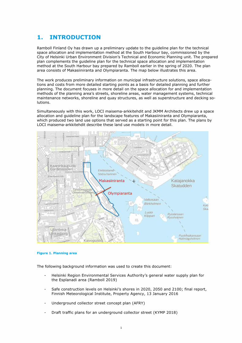
Ramboll Finland Oy has drawn up a preliminary update to the guideline plan for the technical space allocation and implementation method at the South Harbour bay, commissioned by the City of Helsinki Urban Environment Division’s Technical and Economic Planning unit. The prepared
plan complements the guideline plan for the technical space allocation and implementation method at the South Harbour bay prepared by Ramboll earlier in the spring of 2020. The plan area consists of Makasiiniranta and Olympiaranta. The map below illustrates this area.
The work produces preliminary information on municipal infrastructure solutions, space alloca-tions and costs from more detailed starting points as a basis for detailed planning and further
planning. The document focuses in more detail on the space allocation for and implementation methods of the planning area’s streets, shoreline areas, water management systems, technical
maintenance networks, shoreline and quay structures, as well as superstructure and decking so-lutions. Simultaneously with this work, LOCI maisema-arkkitehdit and JKMM Architects drew up a space allocation and guideline plan for the landscape features of Makasiiniranta and Olympiaranta,
which produced two land use options that served as a starting point for this plan. The plans by LOCI maisema-arkkitehdit describe these land use models in more detail.
Figure 1. Planning area
The following background information was used to create this document:
- Helsinki Region Environmental Services Authority’s general water supply plan for
the Esplanadi area (Ramboll 2019)
- Safe construction levels on Helsinki’s shores in 2020, 2050 and 2100; final report,
Finnish Meteorological Institute, Property Agency, 13 January 2016
- Underground collector street concept plan (AFRY)
- Draft traffic plans for an underground collector street (KYMP 2018)

2
- Flood preparation in construction. A guide for determining the lowest construction
levels in shoreline areas, Environmental guide 2014
- Original plans of the South Harbour’s quay structures from the Port of Helsinki’s
archive.
- Plans for quay structures’ renovation carried out in the South Harbour, Port of
Helsinki
- A summary of seabed soundings carried out at various times, Port of Helsinki
- The South Harbour area’s ground survey results from the Soili ground survey reg-
ister, City of Helsinki
- A sediment survey report from the South Harbour, 13 January 2011, Fish and wa-
ter survey/Port of Helsinki
- Katajanokka Harbour: A review of the vehicle exit arrangements’ functionality
(Ramboll 2020).
- Preliminary guideline plan for the technical space allocation and implementation
method at the South Harbour bay, Ramboll Finland Oy 30 April 2020
- Motor traffic connections at South Harbour. A draft plan for a tunnel connection
under Tähtitorninmäki (Draft version AFRY 16 October 2020)
- Space allocation and guideline plan for the landscape features of Makasiiniranta
and Olympiaranta (Draft report 15 January 2021 LOCI maisema-arkkitehdit Oy
and JKMM Architects)
In addition to the above, the area’s current cable maps were used. The plans utilise the ETRS-GK25 coordinate reference system and the N2000 height system. The project team included:
Mikko Juvonen KYMP/MAKA/MYLE Marjaana Yläjääski KYMP/MAKA/ASKA Pekka Nikulainen KYMP/MAKA/LIKE Mirva Koskinen KYMP/MAKA/MAKE Helmer Berndtson Ramboll Finland Mauri Myyrä Ramboll Finland
Toni Talvinen Ramboll Finland Topi Vuorio Ramboll Finland Anni Orkoneva Ramboll Finland
Ada Laitinen Ramboll Finland Kimmo Kykkänen Ramboll Finland

3
2. GUIDELINE PLAN
2.1 Traffic arrangements The starting point for the traffic arrangements has been that the current type of cruise traffic
would no longer operate in Makasiiniranta in the future. Ship traffic would continue to operate from the berth in front of Satamatalo, but there would be no or considerably less car traffic to these ships than currently. Lorry traffic to the ships would cease completely. The task has been to plan the maintenance connections needed for the new land use and ships, and study how large queuing areas would be available for the ships’ car traffic, taking into ac-count the facilities needed for the new land use.
Regarding possible maintenance connections, two alternative solutions were finally reached. In
option 1, maintenance for the new land use and ships is presented from Ehrenströmintie using the existing harbour junction. Maintenance for the new land use would run from the west side of Olympia Terminal and descend into a concrete maintenance tunnel at the northern end of Sa-tamatalo. The maintenance tunnel floor will mainly be at -5.0 m. An indicative location for a maintenance yard and dimensioning for lorry and drawbar trailer combinations have been pre-
sented in the maintenance tunnel. The maintenance tunnel will probably include multiple mainte-nance yards, but their size and location will be determined during further planning. The ships’ maintenance will be handled east of Olympia Terminal. The maintenance connection option 2 will take advantage of the entrance to the current Tähti-torninvuori parking facility from Laivasillankatu. The entrance will have to be enlarged to allow
for a two-way maintenance connection for lorry and drawbar trailer combinations. The parking facility will continue to operate. The maintenance connection will run south from the entrance and then turn east under Laivasillankatu to the new land use. The maintenance tunnel floor will mainly be at -5.0 m. This option, too, presents the indicative location and dimensioning for the
maintenance yard, which will be specified during further planning. Like in option 1, the mainte-nance traffic for ships will be handled from the Ehrenströmintie junction.
With both of these maintenance connections and the new land use, car traffic can be provided with a queuing area and the possibility of operation on the east side of Olympia Terminal passing through the Ehrenströmintie junction. However, current functions must be reorganised in this area. Additionally, the car traffic queuing area will take space from new land use. The queuing area capacity has been estimated at 1,200 metres.

4
Figure 2. Structural concept section of Makasiiniranta’s maintenance tunnel.
2.2 General levelling
2.2.1 Streets and public areas The key factors for the area’s general levelling plans included the predicted sea level rise, local-ised drying arrangements, and the technical and quality requirements of the streets and other transport routes, such as longitudinal gradients and emergency accesses.
The lowest recommended building levels in the Makasiiniranta area are approximately at +3.37. The elevation of Makasiiniranta will be raised to +3.4 next to the new buildings. The pedestrian and recreational areas in the seaward edge zone of Makasiiniranta can be set below the recom-
mended building level. However, not below +2.35. In the current situation, Makasiini Quay is ap-proximately at +2.5 and the harbour yard approximately at +2.0.
The elevation of the current square at the northern end of the new buildings of Makasiiniranta will be raised to approximately +3.0. The street junction to Eteläranta will remain at the current level of approximately +2.5. Due to the built environment, the current elevation in front of Olympia Terminal and Satamatalo cannot be substantially changed. The area on the shore side of the buildings is at +2.3 to +2.4.
The yard deck on the street side of Olympia Terminal is at +8.5 to +8.7. The levels of the streets Ehrenströmintie and Laivasillankatu on the western side of Makasiini-ranta and Olympiaranta will remain the same. Plan option VE1
The public areas between the new buildings of Makasiiniranta will be aligned at +3.4 on the Ma-kasiini Quay side and the current level of Laivasillankatu on the western side. The maintenance route on the west side of Satamatalo will pass under the current yard deck of the harbour at ground level and connect to the entrance of the new maintenance tunnel

5
approximately at +2.0. At its lowest, the floor of the maintenance tunnel under the new building mass will be at -5.0. The maintenance connection height in the tunnel will be 6.0 m. Plan option VE1b
In the parallel option 1b based on option 1, part of the quay area of Makasiiniranta will remain in the use of the harbour as a closed security area (ISPS area). The ISPS area will remain at the current elevation of approximately +2.5 and be separated from the public pedestrian area by a retaining wall. The public area will be raised to the level of +3.4 m. Plan option VE2
The new deck structure proposed for the west side of Satamatalo and the roof of the new build-ings on the southern edge of Makasiiniranta will form a new public outdoor space at one level. The level of the western edge of the new public space will align with Laivasillankatu and the har-
bour’s yard deck. The elevation of the upper surface of the area formed on the roof of the build-ing will be approximately +8.5.
Option 2 presents an alternative maintenance connection using a new rock ramp. At Laivasillan-katu, the floor elevation of the maintenance tunnel will be approximately at -2.1 and the floor of the section under the building will be at -5.0 at its lowest. Otherwise, the levelling principles in the area are the same as in option 1.
The area’s general levelling is illustrated in drawings No 9 and 10. The areal sections are illustrated in drawings No 11 and 12. The longitudinal sections of the maintenance tunnels are illustrated in drawings No 7 and 8. 2.3 Water management
The current state of water management in the planning area is presented in the preliminary guideline plan for the technical space allocation and implementation method at the South Har-bour bay, Ramboll Finland Oy 30 April 2020. The proposed water management solutions are illus-trated in drawings No 13 and 14. 2.3.1 Plan option VE1
A new wastewater and run-off drain will be constructed on Laivasillankatu, and the new proper-ties planned for the Makasiini Terminal area will be connected to it. The preliminary proposal for the required size of the wastewater pipe is 250 mm, while the size of the rainwater run-off pipe is 300–400 mm. The street’s existing water pipe will be used for connections to the water supply network.
The dimensioning of water management must be verified during further planning. For the run-off
drain in particular, its catchment area will have to be clarified in more detail in the future, taking into account the effects of the separate sewerage systems that will expand in the future. If the plan is to expand the use of the Laivasillankatu run-off drain to conduct more of the run-off from the Kaivopuisto area in the future, provisions must be made for this in the pipe size of the run-off drain.
Several existing water management pipes that serve the harbour will be left under the planned buildings, and therefore they must be relocated. Moreover, the 900-mm overflow pipe of the combined sewage network must be moved. Its proposed new location is in the southern corner of Vironallas. Furthermore, the current combined sewage pumping station that serves the harbour must be
transferred from the new construction site and relocated. The pumping station’s proposed new location is in the nortwestern corner of the current harbour area. Combined sewage from the har-bour will be pumped to the existing combined sewer and led to a built combined sewage tunnel
under Tähtitorninmäki.
2.3.2 Plan option VE2

6
The water management solutions required in plan option 2 are otherwise identical to option 1, but the crossing of the existing 600/800 mm combined sewage line with the new maintenance tunnel connection planned may require the pumping of combined sewage or a reorganisation of the tunnel. The maintenance tunnel connection will intersect with the combined sewage line both
on Laivasillankatu and below Tähtitorninmäki, where the combined sewage line runs as a tunnel. The plan prepares for the need to pump combined sewage by reserving space on Laivasillankatu for a new combined sewage pumping station, from where the water will be pumped into the com-bined sewage tunnel under Tähtitorninmäki. The need for pumping must be examined in more detail during further planning as the elevations of the maintenance tunnel are specified. The ex-act elevation of the sewer tunnel must also be determined in more detail. The tunnel solution
must be planned in cooperation with HSY. 2.4 Preparing for floods
The current state of flood preparation in the planning area is presented in the preliminary guide-line plan for the technical space allocation and implementation method at the South Harbour bay,
Ramboll Finland Oy 30 April 2020. In the land use scenarios examined, port operations will not cause similar boundary conditions for the elevations of the quay and edge structures as presented in the original work. In this work, the primary flood protection measure presented is the raising of the new land use area to a level in accordance with the flood protection elevation.
The flood protection solutions described below are also illustrated in drawings 15 and 16, and they are based on LOCI’s draft land use plans. 2.4.1 Plan options VE1 and VE1b
Flood protection in front of the harbour quay and Olympia Terminal can be implemented either structurally, e.g. with a flood wall, or by raising the ground level on the shore side. In the Makasiini Terminal area, the new buildings planned will be protected against floods by rais-ing the surroundings of the new construction to +3.4 m. The shore area will remain at +2.4 to +2.5 m. The realisation of the shore area will need to be addressed in more detail during further planning, and options for the realisation of the shore area have been presented in LOCI’s report
(2021). We propose that flood protection against the sea at Pakkahuone Quay be completed in stages: initially from the current level to +2.8 m, and later to +3.4 m. In the area of Vironallas and the Market Square, flood protection will, at least for the time being, be carried out by means of tem-porary flood protection, such as flood dams.
A flood pumping station has been planned on the south shore for the discharge of run-off from
the Kasarmitori catchment area into the sea. Run-off must be removed by pumping if flooding is simultaneously caused by the sea and a storm and the discharge of surface run-off water into the sea is impeded due to the flood protection structures. The required pumping capacity is several cubic metres per second, and therefore the pumping stations, too, will need plenty of space. A preliminary space allocation of 15 m x 15 m has been presented for the pumping station, which is
based on previous investigations. The pumping station will be equipped with valve chambers, which will prevent seawater from entering the system. In order to ensure that the valve cham-bers are working properly, they must be checked/maintained regularly. In addition to flooding caused by the sea, preparations must be made against flooding due to storms by designing flood conveyance routes for the area. The capacities of both the existing combined sewage system and the future rainwater run-off
network have been determined for specific flow rates resulting from heavy storms. Rainfall that exceeds this capacity, as well as any disruptions in the sewage system, can cause run-off water to flood via inspection wells onto the streets. The flood conveyance routes will primarily be cre-
ated by designing the streets’ gradients and cross-sections in a way that allows stormwater to run along the street network in a controlled fashion if the sewage system’s capacity is exceeded.
Drying the area under the deck requires property-specific rainwater run-off and flood manage-ment solutions, including individual pumping stations for each property.
7
Option 1b In the parallel option 1b based on option 1, part of the quay area of Makasiiniranta will remain in
the use of the harbour as a closed security area (ISPS area). The flood protection for the new buildings will be realised with the same principle as in option 1. The public area will be raised to the level of +3.4 m. The elevation difference between the ISPS area and the public pedestrian area will be addressed by implementing a new retaining wall at the border between these areas. 2.4.2 Plan option VE2
The flood protection solutions proposed for the area are the same as in plan option 1. The flood protection of the building planned in this solution for the corner of Makasiini Quay and Pakkahuone Quay must be solved property-specifically, e.g. with temporary flood dams/walls.
The building is located at a point where the raised ground level of +3.4 m merges with the cur-rent ground level of approx. +3.0 m.
2.5 Geotechnology and shoreline structures 2.5.1 Current situation Makasiiniranta and Olympiaranta
The current situation in the planning area is presented in the preliminary guideline plan for the technical space allocation and implementation method at the South Harbour bay, Ramboll Finland Oy 30 April 2020. Percussion drilling has been carried out by the Port of Helsinki at Makasiiniranta after the comple-
tion of the guideline plan report. The latest ground survey points are presented on the updated
Makasiiniranta ground survey map in drawing No 40. The ground survey diagrams regarding the new drilling work are shown in the updated geotechnical sections in drawings No 43–45. Based on the drilling, a more specific estimate on the level of the bedrock surface in the area has been obtained. The bedrock’s surface level in the area is approximately -10 m – -25 m. 2.5.2 Quay renovation
General The guideline solutions for the renovation of the quay structures in the planning area are pre-sented in the preliminary guideline plan for the technical space allocation and implementation method at the South Harbour bay, Ramboll Finland Oy 30 April 2020, which includes an assess-
ment of the quays’ long-term renovation needs and principles from a geotechnical and structural point of view in order to determine the space requirements and costs of future urban planning
solutions. The proposed solutions are conceptual and preliminary in nature. This document does not include an assessment of the renewal of systems connected to the Port of Helsinki’s operative functions, or any effects or costs resulting from the renewal of the quay structures that pertain to these functions. The quays extend to the harbour yard at various widths. Their renovation re-quires that the work be carried out in phases and coordinated with the harbour’s operative func-
tions, and future plans must contain more details on this. The berths and other structures in the harbour areas belong to the Port of Helsinki. Matters re-lated to the administrative aspects, agreements and implementation of the quays’ renovation ap-ply to the Port of Helsinki. Decisions about any investments in the harbour are made by the Port of Helsinki.
Different land use options will have little effect on the quays’ renovation methods. Only the flood barrier locations proposed in different plan versions will have an impact on the quays. The walls’ conceptual attachment methods to the new quay structures are illustrated in drawing No 31.
Makasiiniranta and Olympiaranta

8
In the updated land use plans VE1, VE1b and VE2 in accordance with this report, the renovation of Makasiini and Olympia Quays is presented to be carried out the same way as in the original guideline plan of 30 April 2020 (drawings No 26 and 31).
In land use options VE1 and VE2, the quay edge will remain as it is and port operations will com-pletely move form Makasiini Quay to Olympia Quay, which will make Makasiiniranta a public area. This technical guideline plan proposes that the quay edge be moved approximately 2.0 m sea-ward due to the quays’ renovation method, which will provide some additional space for land use on the shore in the future. This additional space has not been taken into account in the architec-tural plan.
In the parallel option 1b based on land use option 1, part of Makasiini Quay will remain in the use of the harbour. Within the security area, the shore’s elevations will be left at the current level as the rest of the public shore area rises to the flood protection level of approximately +3.4. The quay renovation method can be considered the same as in the other land use options. On the
border of the ISPS area, a retaining wall structure enabling the elevation difference can be at-tached to the pile slab required for the renovation of the quay.
As the elevations of the shore become more precise, the quay renovation plan must be updated if necessary. The general principle of raising the elevation of the shore to approximately +3.4 pre-sented in the land use options will not require any changes to the principles for the renovation of quay structures presented in the original work. From the perspective of the quay renovation, it would be advantageous not to lower the elevation of the shore much below the currently lowest
level (approximately +2.3), so that the cast-in-situ and steel composite structures of the renova-tion structures can be made in dry conditions above the current mean water level (+0.2). 2.5.3 Foundation engineering
Makasiiniranta
The land use options require the maintenance traffic in the area to be led below the current ground level into a maintenance tunnel. Plan options VE1 and VE1b: In this land use option, the general level of Makasiiniranta will be raised to the flood protection
level of +3.4. The effect of the additional load on the shore’s stability caused by raising the level can be controlled using the quay’s renovation structures, where a solid retaining wall structure extending to the hard ground in front of the current quay edge will effectively break up the slip surfaces. On the Olympia Quay side, the general level will remain at roughly the current level in order to maintain the continuity of port operations.
The new building masses for Makasiiniranta have been presented in the land use plan to be spread over the entire length of the shore. The new three-storey buildings will be built on a pile
foundation. The piles used will be drilled or driven, depending on the results of further detailed ground surveys carried out in connection with further planning. The penetration rate of the piles is determined by the quality of the filling, for which there is currently little survey data. Among the fill, there are old structures that hinder piling, such as old timber caisson quay structures. The extent of the buildings’ foundation structures towards the shore must be planned in accord-
ance with the space required for the renovation of the quay structure. The seaward areal stability of the building masses presented in the land use plans must be taken into account when planning the time of the quay renovation and the construction of buildings. Due to the layers of clay under the old quay structure, the area must be brought to a level of safety sufficient for stability before any buildings are constructed. One option to ensure stability are the quay renovation measures presented in this guideline plan.
In this land use option, maintenance traffic to Makasiiniranta has been led from the southern end of the area on the western side of the current Olympia Terminal building, utilising the existing
deck structure. On the north side of the current deck, the maintenance route will dive below the ground level of the current harbour yard and the route is designed as a concrete tunnel. The western edge of the concrete tunnel will follow the walls of the new buildings in such a way that
the wall structure of the tunnel can simultaneously serve as the foundation for the western edge of the buildings. The tunnel route will run under the new building mass. The preliminary plan is to
9
implement the tunnel between two drilled pile walls. The drilled pile wall will be implemented as a solid and watertight wall structure, where the piles will be generally extended to approximately -10 and at regular intervals inside the bedrock, in order to ensure the vertical bearing capacity of the buildings and the tunnel. If necessary, the background of the pile wall will be sealed, e.g.
with jet grouting extending below the floor slab, to ensure watertightness. The floor and ceiling slabs of the maintenance traffic tunnel will be made as a reinforced concrete slab/beam bridge structure. The ceiling slab/beam bridge will be built on the drilled pile walls as a supported structure and the floor slab between the pile walls at the level required by the tunnel traffic. The floor slab of the maintenance tunnel must be anchored vertically to the bedrock against lifting forces, taking into account future flood levels, which also represent the future
groundwater level in the filling area. The concreted and reinforced piles will be bonded with the concrete casts of the floor and ceiling slabs in order to attach them rigidly to each other. The drilled pile walls will also serve as retaining walls for the concrete structures during casting and enable the casting to be carried out under dry conditions.
The foundation engineering measures of this land use option are tentatively presented in a layout plan in drawing 41 and in cross-sections in drawings 43–45.
Plan option VE2: In this land use option, the general levelling of Makasiiniranta will be as in option 1. In this op-tion, the new building masses of Makasiiniranta are generally presented as lower than in option 1 in order to preserve the views. Construction to the north of the current Satamatalo is presented
partly in one storey, where the roof of this single-storey structure spreads as a deck-like struc-ture and recreational area at the same level as the current deck to the west of Satamatalo (ap-prox. +8 to +8.5). The new building masses will be built on a pile foundation as in option 1. In this land use option, maintenance traffic has been led to the new block area via a rock tunnel, the access to which is from Laivasillankatu. The harbour’s maintenance traffic is presented
aboveground from the north, as in option 1. The rock structural engineering of the rock tunnel
section has been presented in a separate report (Afry Finland Oy 16 October 2020, South Har-bour traffic connection via the Tähtitorninmäki rock resource). The tunnel connection will change from a rock tunnel to an underground concrete tunnel below Laivasillankatu, from where the sec-tion of the tunnel on the Makasiiniranta side is planned to be implemented between two drilled pile walls, as in option 1. The tunnel section below Laivasillankatu will be pushed down enough to be able to make the ceiling structure of the tunnel thick enough (approx. 2.0 m) and to restore the street structure atop the tunnel. The traffic on Laivasillankatu will have to be interrupted for
the duration of the work until the drilled pile walls and access bridges have been installed. The foundation engineering measures of this land use option are tentatively presented in a layout plan in drawing 42 and in cross-sections in drawings 43–45.
2.6 Structural solutions
2.6.1 Makasiiniranta The preliminary design of the maintenance tunnel structures is based on the dimensions of the route as well as the buildings atop the deck.
In the preliminary calculations, the same principles and loads have been used in the dimension-ing of the maintenance tunnel as in the original guideline plan (RFi Oy 30 April 2020). This work presents rough fire and rescue solutions for the concrete tunnel section of the mainte-nance connection using the principles of the original work. The fire and rescue solutions must be specified during further planning.
10
3. COSTS
3.1 General
The costs were calculated using Fore’s objective budget calculation. The unit costs miss-
ing from the objective budget calculation were calculated using Fore’s plan cost assess-ment and expert estimates. The area multiplier used was 1.10, and the implementation
environment multiplier was 1.02. The prices were from July 2020.
The costs of flood protection, quay renovation and other special structures, as well as preconstruction, were estimated by using unit prices provided by an expert, which were
based on similar projects carried out in the past.
The cost estimates do not include the cost of moving or replacing structures connected to
the Port of Helsinki’s operations.
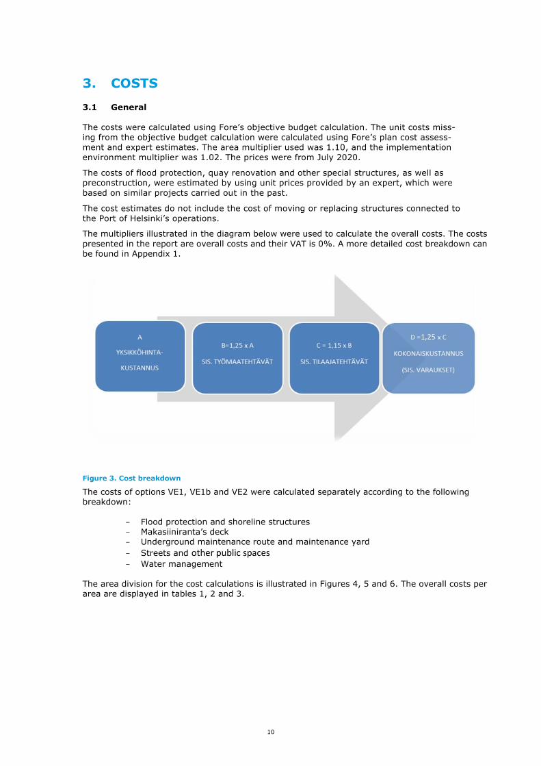
The multipliers illustrated in the diagram below were used to calculate the overall costs. The costs
presented in the report are overall costs and their VAT is 0%. A more detailed cost breakdown can be found in Appendix 1.
Figure 3. Cost breakdown
The costs of options VE1, VE1b and VE2 were calculated separately according to the following breakdown:
- Flood protection and shoreline structures - Makasiiniranta’s deck - Underground maintenance route and maintenance yard
- Streets and other public spaces - Water management
The area division for the cost calculations is illustrated in Figures 4, 5 and 6. The overall costs per area are displayed in tables 1, 2 and 3.

11
Figure 4. Area division for cost calculations VE1
Table 1. Costs per area VE1
VE1
Flood protec-tion and shoreline structures
Deck structure
Underground maintenance
route and yard
Street and other pub-lic spaces
Water manage-
ment Total
1 Maintenance tun-nel €39.1 million
€39.1 mil-lion
2 Makasiini Quay €45.9 million €2.9 mil-
lion €48.8 mil-
lion
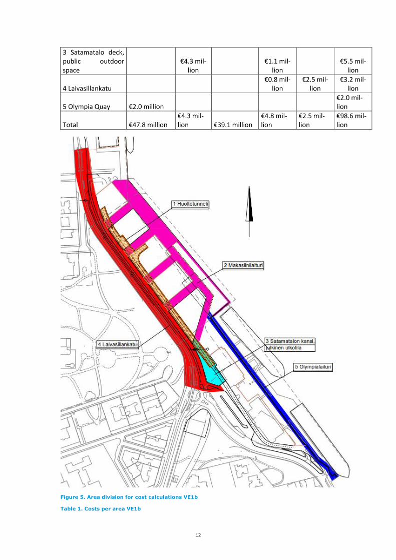
12
3 Satamatalo deck, public outdoor space
€4.3 mil-lion
€1.1 mil-lion
€5.5 mil-lion
4 Laivasillankatu €0.8 mil-
lion €2.5 mil-
lion €3.2 mil-
lion
5 Olympia Quay €2.0 million €2.0 mil-lion
Total €47.8 million €4.3 mil-lion €39.1 million
€4.8 mil-lion
€2.5 mil-lion
€98.6 mil-lion
Figure 5. Area division for cost calculations VE1b
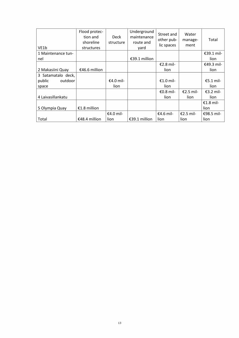
Table 1. Costs per area VE1b
13
VE1b
Flood protec-tion and shoreline structures
Deck structure
Underground maintenance
route and yard
Street and other pub-lic spaces
Water manage-
ment Total
1 Maintenance tun-nel €39.1 million
€39.1 mil-lion
2 Makasiini Quay €46.6 million €2.8 mil-
lion €49.3 mil-
lion
3 Satamatalo deck, public outdoor space
€4.0 mil-lion
€1.0 mil-lion
€5.1 mil-lion
4 Laivasillankatu €0.8 mil-
lion €2.5 mil-
lion €3.2 mil-
lion
5 Olympia Quay €1.8 million €1.8 mil-lion
Total €48.4 million €4.0 mil-lion €39.1 million
€4.6 mil-lion
€2.5 mil-lion
€98.5 mil-lion

14
Figure 6. Area division for cost calculations VE2
Table 2. Costs per area VE2
VE2
Flood protec-tion and shoreline structures
Deck structure
Underground maintenance
route and yard
Street and other pub-lic spaces
Water manage-
ment Total
1 Maintenance tunnel €37.2 million €37.2 mil-lion
2 Makasiini Quay €46.2 million €2.2 mil-lion
€48.4 mil-lion
3 Deck, public out-door space
€3.2 mil-lion
€3.2 mil-lion
4 Satamatalo deck, public outdoor space
€4.3 mil-lion
€1.2 mil-lion
€5.6 mil-lion
5 Laivasillankatu €0.8 mil-lion
€2.5 mil-lion
€3.3 mil-lion

15
6 Olympia Quay €2.0 million €2.0 mil-lion
Total €48.2 million €4.3 mil-lion €37.2 million
€7.4 mil-lion
€2.5 mil-lion
€99.7 mil-lion
3.2 Flood protection and shoreline structures The cost of the quays’ renovation was calculated per one metre of quay by using an expert’s unit
prices and amounts corresponding with the quay structures’ structural concept sections (drawing No 31) presented in the original guideline plan. The quay structures’ cost per running metre was multiplied by the length of the quay sections to be renovated in running metres in order to deter-mine the total costs. Approximately 20% of the filling material that must be excavated in order to carry out the quay renovations was considered to be contaminated when calculating the costs. The quays’ costs per running metre are described in Appendix 1.
The cost of flood protection was determined either as part of the quays’ cost calculations or as a separate plan cost assessment. It is included in a quay’s costs if the flood protection structure is part of the elevation of the quay’s seaward edge, and excluded if the flood protection is imple-mented at a separate location, for example as part of a protective fence (ISPS area). The basis for determining the running metre costs of the flood protection structures and other special struc-tures is presented in Appendix 1.
The pile slab required for the renovation of Makasiini Quay will extend approximately 20.5 m landward from the current quay edge. The intersection of the rear edge of the pile slab with the buildings of the land use has been taken into account in the cost as a provision for the additional demolition of the current quay structure. The costs of flood protection at Olympia Quay consist of the construction of the flood barrier pro-
posed for the ISPS fence line at +3.4. The costs include excavation, a reinforced concrete footing
and wall structure and a granite slab wall. The ISPS fence line for Makasiini Quay presented in land use option VE1b also requires the construction of a flood barrier / retaining wall at the fence line. On the Makasiini Quay section, this retaining wall has been proposed to be attached to the quay’s pile slab.
3.3 Satamatalo’s deck structures Both of the Satamatalo deck options were calculated using a column interval of 12 m x 12 m. The costs include the concrete frame, columns, beams, slab and deck structure, as well as the surface structures according to the structural concept section of the original guideline plan (Figure 6). The costs of surface structures above the filter cloth are presented in Section 3.5. The foundation
costs include 6 m x 6 m x 2 m column footing, piling and earthworks.
Figure 7. Structure of the deck structure

16
The public outdoor space 3 on the Makasiiniranta deck and/or on the roof of the buildings pre-sented in land use option 2 has been calculated according to the area of the public outdoor space only for its surface structures. The costs for the other deck structures have been assumed to be the responsibility of the plot and have therefore been excluded from this work.
3.4 Underground maintenance route and yard The underground maintenance route has been calculated as a concrete tunnel structure in both
land use options. The costs include drilled pile walls for the tunnel’s walls, excavation work, rein-forced concrete ceiling and floor slabs, rock anchors and asphalt paving. The height of the drilled pile walls has been estimated according to the average height of the tunnel route. Of the earth mass to be excavated, 20% is estimated to be contaminated.
The costs of the rock section of the maintenance tunnel are presented in the report ‘Eteläsa-taman ajoyhteydet – Luonnossuunnitelma tunneliyhteydestä Tähtitorninmäen alitse’ prepared by
Afry on 16 October 2020. 3.5 Streets and other public spaces, water management The unit prices for the construction of the street and other public areas include the earthworks,
kerbs, surface materials, structural layers, embankment materials and drying. All the public areas are of high quality. The costs include lighting. In all options, the street-related costs of Laivasillankatu only include the widening of the cycling and pedestrian lanes. The costs do not include a possible future change to the cross-section of the street. The costs of the widening include the demolition of the existing retaining wall and
fence and the relocation of the shared-use pylons.
The costs of the deck structures include the surface structures above the filter cloth as shown in Figure 6. The deck’s other costs are described in Section 3.3. The costs of the underground maintenance tunnel and the driving lane of the maintenance yard are presented in full in Section 3.4. The water management unit prices include the earthworks, materials, installation and
trench filling. When further plans are made, certain piping foundation solutions and excavation work may cause additional costs as the gravity collectors’ height is determined in more detail. The pumping station costs were estimated based on the costs of other similar site designs. The cost estimates do not include the cost of property pipelines. In all options, the water management costs include the new combined sewage pumping station.
VE1 and VE1b
The costs of Makasiiniranta’s VE1 and VE1b include the expansion and water management of Lai-vasillankatu, the costs of the new public outdoor space at Makasiini Quay and the surface struc-tures of the Satamatalo deck structure, as illustrated in Figures 4 and 5. The costs of VE1b do not include the costs of the ISPS area or the quay area and transport connection of the high-speed vessel terminal.
VE2 The costs of Makasiiniranta’s VE2 include the expansion and water management of Laivasillan-katu and the costs of the new public outdoor space at Makasiini Quay, as illustrated in Figure 6. The costs of the Satamatalo deck structure and the deck structure of the public outdoor space in-clude the surface structures only.
4. CONSIDERATIONS FOR FURTHER PLANNING
This guideline plan was created to provide support to the city’s detailed planning and the area’s further development with the intention of highlighting certain principles for further plans. Below is

17
a list of things highlighted during the creation of this document, which should be reviewed more carefully in the future. Traffic-related issues
• More detailed planning of the maintenance yards: number, locations and dimen-
sions
• Arrangements of the Tähtitorninvuori parking facility during the work
Water management
• The planned water management pipe sizes must be verified once the proposed con-
struction area dimensions have been specified. In particular, the dimensioning of
the run-off drains must be checked and preparations made for separate drainage.
• In option 2, the underground maintenance tunnel solution must be planned in co-
operation with HSY and its effects on the current combined sewer must be investi-
gated in more detail. Possible need for pumping combined sewage and the location and dimensioning of the pumping station must be specified. The elevations of the
current combined sewer / tunnel need to be specified.
Preparing for floods
• The flood protection solutions proposed for the shoreline will be determined once
the draft land use plans and technical criteria become more detailed.
• The surface run-off route concepts and the required storm run-off drains’ flood ca-
pacities must be specified.
• The necessary property-specific flood protection measures, e.g. at the Makasiini
Quay area, must be determined.
• The location, capacity and elevation levels of the floodwater pumping station must
be assessed in more detail in the future.
Geotechnology and foundation engineering In addition to the geotechnical follow-up measures proposed in the original technical guideline
plan for land use at South Harbour (RFi Oy, 30 April 2020), the following further examinations are suggested.
• Investigation of the filling area between Makasiini Quay and Laivasillankatu with
supplementary ground surveys.
- Determination of the quality of the fill with static-dynamic penetration and soil sample tests to assess pile penetration, particularly at the estimated
foundation line of the planned building masses.
- Determination of the position of the bedrock surface and rock quality with percussion drilling, particularly at the location of the planned concrete tun-
nel to evaluate the lengths of the drilling piles and the rock anchoring.
Structural engineering
• Specification of the fire and rescue plan for the concrete tunnel section of the
maintenance tunnel connection.

18