PRELIMINARY STUDIES ON LARGE-SCALE...
6
PRELIMINARY STUDIES ON LARGE-SCALE HIGHER-ORDER AMBISONIC SOUND REINFORCEMENT SYSTEMS Jörn Nettingsmeier 1 , David Dohrmann 2 1 Freelance Audio Engineer ([email protected]) 2 Applications Engineer, Adamson Europe GmbH ([email protected]) Abstract: Can Higher-order Ambisonic systems be scaled to cater to many hundreds or even thousands of listeners? If yes, what are the esthetic consequences of doing so? The authors have implemented a third-order horizontal system using eight short line-arrays and four bass stacks covering an indoor area of 20 by 15 metres, to explore the suitability of Ambisonics for large-scale sound reinforcement. Possible applications include live and dance events with musicians or DJs who might want to exploit space as an additional degree of freedom in their performances, or rock opera shows where full surround is desired. The test system has performed very well in subjective evaluation across a large area, despite the fact that the vast majority of listeners will be outside the boundary of correct reconstruction. Line arrays can be designed to deliver almost constant level over a given area, so that the limiting constraint for the performance of such “overstretched” Ambisonic systems is runtime. We will try to analyze the behavior of several localization cues under these conditions: at which distance from the center are they expected to break down, and what are their failure characteristics? Key words: Higher-order Ambisonics, commercial sound reinforcement, line arrays 1 INTRODUCTION Most Ambisonic systems implemented so far have been targeted at comparably small audiences, mostly in the context of electro-acoustic music. Earlier attempts at larger systems for theatrical or dance events as described by Malham in 1992 [1] and 1996 [2] were limited to first order Ambisonics. More recently, the Glastonbury Festival in the UK has featured second order Ambisonic rigs since 2006 in one of its performance venues, consisting of six stacks of horn speakers [3, 4]. While first-order systems can provide very pleasant envelopment and listener immersion, their unstable localization and lack of focus makes them unsuitable for applications where accurate projection of virtual sources over a large listening area is required. We examine an octagonal setup capable of up to third- order horizontal reproduction. We are using line array systems rather than traditional stacks, since they can be designed to deliver sound over long distances with very little loss of pressure by applying the correct amounts of splay and curvature (as described by Heil et al. 2003 [5]), and so ensure uniform coverage of the listening area. If the system under test performs as well as small-scale third-order rigs, it should be suitable for demanding surround applications that require precise localization in addition to good envelopment. When scaling an Ambisonic system to a large listening area, it is important to realize that the size of the sweet spot (that is, the area of perfect sound field reconstruction) is a function of the frequency only, and does not increase along with the array diameter. For larger systems, we must assume that practically the entire audience is outside the sweet spot except at very low frequencies. Therefore, quality assessments performed on smaller systems may not apply. Moreover, we will easily be able to reach diameters where the runtime differences of the speaker signals at the listener position might invalidate assumptions about localisation fusion that are taken for granted in small systems [6]. As we scale up, even the notion of „simultaneity“ begins to vanish, since the resulting rhythmic pattern between a frontal and a rear source will begin to „swing“ in various ways depending on the listener position, which constitutes an artistic challenge for live performers and imposes some esthetic constraints on the choice of material that can be played back. 2 CONFIGURATION OF THE TEST SYSTEM The system under test comprised eight stacks of three Adamson Metrix line-array elements each. The Metrix system features an 8.5“ low-mid driver and a 3“ dia- phragm to 1.4“ exit compression tweeter mounted on a proprietary Adamson soundchamber. It is tuned for a ver- tical opening angle of 5° and a horizontal coverage area of 120° [7]. The line arrays were stacked on empty flight- cases, roughly at ear height, to ease the setup process. This is obviously detrimental to uniform coverage of large audiences – for production use, the arrays should be flown or at least be brought well above head height to AMBISONICS SYMPOSIUM 2011 June 2-3, Lexington, KY
-
Upload
truongkien -
Category
Documents
-
view
216 -
download
0
Transcript of PRELIMINARY STUDIES ON LARGE-SCALE...

PRELIMINARY STUDIES ON LARGE-SCALE HIGHER-ORDER AMBISONIC SOUND REINFORCEMENT SYSTEMS
Jörn Nettingsmeier1, David Dohrmann2
1 Freelance Audio Engineer ([email protected])2 Applications Engineer, Adamson Europe GmbH ([email protected])
Abstract: Can Higher-order Ambisonic systems be scaled to cater to many hundreds or even thousands of listeners? If yes, what are the esthetic consequences of doing so?
The authors have implemented a third-order horizontal system using eight short line-arrays and four bass stacks covering an indoor area of 20 by 15 metres, to explore the suitability of Ambisonics for large-scale sound reinforcement. Possible applications include live and dance events with musicians or DJs who might want to exploit space as an additional degree of freedom in their performances, or rock opera shows where full surround is desired.
The test system has performed very well in subjective evaluation across a large area, despite the fact that the vast majority of listeners will be outside the boundary of correct reconstruction. Line arrays can be designed to deliver almost constant level over a given area, so that the limiting constraint for the performance of such “overstretched” Ambisonic systems is runtime. We will try to analyze the behavior of several localization cues under these conditions: at which distance from the center are they expected to break down, and what are their failure characteristics?
Key words: Higher-order Ambisonics, commercial sound reinforcement, line arrays
1 INTRODUCTION
Most Ambisonic systems implemented so far have been targeted at comparably small audiences, mostly in the context of electro-acoustic music.
Earlier attempts at larger systems for theatrical or dance events as described by Malham in 1992 [1] and 1996 [2] were limited to first order Ambisonics. More recently, the Glastonbury Festival in the UK has featured second order Ambisonic rigs since 2006 in one of its performance venues, consisting of six stacks of horn speakers [3, 4].
While first-order systems can provide very pleasant envelopment and listener immersion, their unstable localization and lack of focus makes them unsuitable for applications where accurate projection of virtual sources over a large listening area is required.
We examine an octagonal setup capable of up to third-order horizontal reproduction. We are using line array systems rather than traditional stacks, since they can be designed to deliver sound over long distances with very little loss of pressure by applying the correct amounts of splay and curvature (as described by Heil et al. 2003 [5]), and so ensure uniform coverage of the listening area.
If the system under test performs as well as small-scale third-order rigs, it should be suitable for demanding surround applications that require precise localization in addition to good envelopment.
When scaling an Ambisonic system to a large listening area, it is important to realize that the size of the sweet spot (that is, the area of perfect sound field
reconstruction) is a function of the frequency only, and does not increase along with the array diameter. For larger systems, we must assume that practically the entire audience is outside the sweet spot except at very low frequencies. Therefore, quality assessments performed on smaller systems may not apply.
Moreover, we will easily be able to reach diameters where the runtime differences of the speaker signals at the listener position might invalidate assumptions about localisation fusion that are taken for granted in small systems [6]. As we scale up, even the notion of „simultaneity“ begins to vanish, since the resulting rhythmic pattern between a frontal and a rear source will begin to „swing“ in various ways depending on the listener position, which constitutes an artistic challenge for live performers and imposes some esthetic constraints on the choice of material that can be played back.
2 CONFIGURATION OF THE TEST SYSTEM
The system under test comprised eight stacks of three Adamson Metrix line-array elements each. The Metrix system features an 8.5“ low-mid driver and a 3“ dia-phragm to 1.4“ exit compression tweeter mounted on a proprietary Adamson soundchamber. It is tuned for a ver-tical opening angle of 5° and a horizontal coverage area of 120° [7]. The line arrays were stacked on empty flight-cases, roughly at ear height, to ease the setup process. This is obviously detrimental to uniform coverage of large audiences – for production use, the arrays should be flown or at least be brought well above head height to
AMBISONICS SYMPOSIUM 2011June 2-3, Lexington, KY

avoid extreme sound levels close to the stacks and loss of level on the opposite site of the listening area due to sha-dowing and absorption by the crowd.
The line arrays were complemented by four floor stacks of two Metrix Sub units, each of which houses two 15“ bass drivers [8]. For the test, they were used in standard omnidirectional mode.
The system was driven by XTA DP428 controllers and Lab.Gruppen FP series amps. The crossover frequency was set to 100 Hz, and the filters had a slope of 24 dB/oct with Linkwitz-Riley characteristics.
The four frontal speaker stacks were aligned to precise angles with the help of a laser angle gauge. Bearings for the rear half were then obtained by sighting along the center marker to the respective opposite stack. Due to space restrictions, the physical distances to the nominal center varied from 6.92 m to 10.25 m, with an average of 8.70 m. After delay compensation, the effective array dia-meter was 20.5 m (see Figure 1).
The levels of the speaker stacks were matched to within +/- 0.1dB using a pink-noise test signal and a measure-ment microphone at the center of the ring.
We decided to use a mixed-order approach for the bass and mid/hi systems. As mentioned before, the size of the sweet spot is a function of the frequency:
rN2⋅
cf
(1)
where r is the sweetspot radius at frequency f for order N, and c is the speed of sound [9].
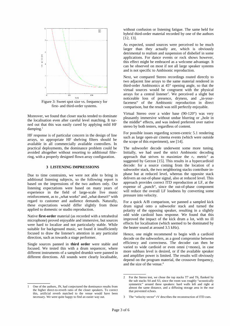
Since the size of the sweet spot increases at low frequen-cies (Figure 3), we decided to save a few amp channels, cable runs and possibly rigging points and drive the subs in first order only.
We placed the subs in between the line-arrays in order to have perfect symmetry for Stereo vs. Ambisonics A/B comparison. In normal operations, the subs can be flown over every other line-array to simplify rigging.
For the tops, we used the open-source AmbDec dual-band decoder and a matrix based on the third-order octagon example setup, with only the distances modified to match our rig. The AmbDec decoder was designed by Fons Adriaensen and is available under the GNU General Public License [10]. The software runs on Linux or Mac OS X. It is considered state of the art and fulfils all crite-ria for correct Ambisonic reproduction [11].
The subs were driven by a second AmbDec instance using a first-order square configuration. A delay in the XTA controllers was used to align the phases of subs and tops.
When resorting to delays to compensate for deviations from a circular arrangement, the horizontal coverage of the speaker systems must be considered: it is important that all arrays cover the entire listening area without too much HF rolloff. In our case (see Figure 2), the triangular area subtended by T1, T2 and T8 in the front left was out-side the nominal coverage area of T2. The same held for the front right and the corresponding rear regions. In these „dead zones“, sources emanating from the direction of the respective „problem speaker“ would sound duller and less focused.
Page 2 of 6
Figure 1: Overview of the test system. The white dashed arrow points to the front. Tops (connected by green lines) were arranged in a regular octagon starting at 22.5°, subs
(red) in a square starting at 45° (counter-clockwise).
Figure 2: Nominal coverage areas of the tops (120°) are indicated as brown sectors. The white circles are at 5 and 10 m radius, respectively. Distance errors were corrected with delay relative to T8. Note the coverage gaps in the
corners of the setup.
Moreover, we found that closer stacks tended to dominate the localisation even after careful level matching. It tur-ned out that this was easily cured by applying mild HF damping.1
HF response is of particular concern in the design of line arrays, so appropriate HF shelving filters should be available in all commercially available controllers. In practical deployments, the dominance problem could be avoided altogether without resorting to additional filte-ring, with a properly designed flown array configuration.
3 LISTENING IMPRESSIONS
Due to time constraints, we were not able to bring in additional listening subjects, so the following report is based on the impressions of the two authors only. Our listening expectations were based on many years of experience in the field of large-scale live music reinforcement, as to „what works“ and „what doesn't“ with regard to customer and audience demands. Naturally, these expectations would differ slightly from those applied to domestic or studio reproduction.
Native first-order material (as recorded with a tetrahedral microphone) proved enjoyable and immersive, but sources were hard to localize and not particularly stable. While suitable for background music, we found it insufficiently focused to draw the listener's attention in any particular direction, such as towards a stage performer.
Single sources panned in third order were stable and focused. We tested this with a drum sequencer, where different instruments of a sampled drumkit were panned in different directions. All sounds were clearly localisable,
1 One of the authors, JN, had conjectured the dominance results from the higher direct-to-reverb ratio of the closer speakers. To correct this, artificial reverb matched to the venue would have been necessary. We were quite happy to find an easier way out.
without confusion or listening fatigue. The same held for hybrid third-order material recorded by one of the authors [12, 13].
As expected, sound sources were perceived to be much larger than they actually are, which is obviously detrimental to realism and suspension of disbelief in some applications. For dance events or rock shows however, this effect might be embraced as a welcome advantage. It can be observed on most if not all large speaker systems and is not specific to Ambisonic reproduction.
Next, we compared Stereo recordings routed directly to two adjacent line arrays to the same material rendered in third-order Ambisonics at 45° opening angle, so that the virtual sources would be congruent with the physical arrays for a central listener2. We perceived a slight but noticeable loss of presence, dryness, and „in-your-faceness“ of the Ambisonic reproduction in direct comparison, but the result was still perfectly enjoyable.
Virtual Stereo over a wider base (90-120°) was very pleasantly immersive without undue blurring or „hole in the middle“ effects, and was indeed preferred over native stereo by both testers, regardless of content.
For possible issues regarding screen-centric 5.1 rendering such as large open-air cinema events (which were outside the scope of this experiment), see [14].
The subwoofer decode underwent some more tuning. Initially, we had used the strict Ambisonic decoding approach that strives to maximize the rV metric3 as suggested by Gerzon [15]. This results in a hypercardioid decode: for a source coming from the location of a subwoofer stack, the two neighboring stacks contribute in-phase but at reduced level, whereas the opposite stack delivers an out-of-phase signal, also at reduced level. This approach provides correct ITD reproduction at LF, at the expense of „punch“, since the out-of-phase component will reduce the overall LF loudness by converting some pressure into velocity.
For a quick A/B comparison, we panned a sampled kick drum signal onto a subwoofer stack and turned the polarity of the opposing speaker, resulting in a slightly odd wide cardioid bass response. We found that this improved the impact of the kick drum a lot, with no ill effects for localisation (which seemed to be dominated by the beater sound at around 3.5 kHz).
Hence, one might recommend to begin with a cardioid decode on the subwoofers, as a good compromise between efficiency and correctness. The decoder can then be varied to wide cardioid or even omni (=mono), in case more subbass level is desired, or if the available speaker and amplifier power is limited. The results will obviously depend on the program material, the crossover frequency, and the size of the venue.4
2 For the Stereo test, we chose the top stacks T7 and T6, flanked by the sub stacks S4 and S3, since the room was roughly “acoustically symmetric” around these speakers: hard walls left and right at almost the same distance, and a diffusing storage area in the rear that prevented echoes.
3 The “velocity vector” rV describes the reconstruction of ITD cues.
Page 3 of 6
Figure 3: Sweet spot size vs. frequency for first- and third-order systems.

During the entire listening session, both testers moved around the listening area to check for image deterioration. We considered the performance throughout the listening area to be perfectly adequate for paying customers. When moving away from a virtual source, we were astonished to find that the source would not collapse into the opposite speaker stack until we were within a meter of that stack. The auditory image would become gradually more vague as the listener moved away from the center, but never so much as to fail entirely or become irritating.
Subtle phasing artefacts were noticeable with some sustained broadband sounds when moving about, but they were so low as to be acceptable. The reverberation in the venue might have been helpful here. Under free-field conditions, staggered delay times or allpass filters could be employed to reduce HF phasing, if required.
We did not notice any timbral defects, at least none that stood out in the context of any large sound reinforcement system under real-world conditions.
4 THEORETICAL CONSIDERATIONS
For listeners outside the sweet spot (i.e. the vast majority in any practical Ambisonic deployment), the ITD cues for low-frequency localization as described by the rV metric will be incorrect.
Away from the center, the reconstructed ITDs will gradually shift out of phase as the frequency increases, resulting in increasingly skewed directional cues. The effect resembles the inconsistency of ITD information at higher frequencies, as λ/2 approaches the distance between the ears.
Apparently, the brain is able to identify high-frequency ITD as misleading, and discards it in favor of interaural level difference (ILD) cues.
Our subjective listening impression on the test system suggests that inconsistent low-frequency ITDs will be discarded as well, without ill effects for localization, provided that robust HF ILD cues are available at the same time.5
4 For small indoor venues, a correct hypercardioid decode could be beneficial as it increases the „virtual volume“ of the space and might counteract the excitation of room nodes, providing a cleaner, less boomy bass.
5 It should be noted that other types of ITD information, such as transient or envelope TD, which have been demonstrated to produce localization cues even for high-frequency carrier signals [16], will
Hence, we assume that the quality of localization is adequately described by the rE metric alone for the majority of listeners6.
We are now facing a superimposed soundfield comprising eight sound sources (or more, if we take reflections into account) at different levels. As the listener moves away from the center, these sources become increasingly incoherent, and their arrival times change dramatically. Just as strict rV reconstruction is largely irrelevant for the most part of the listening area, so is the classical notion of summing localization, because is limited to a time window of 1-2 ms [17].
Let us consider a worst-case scenario for the system under test: a virtual source is produced at an azimuth angle of 0°, and the listener is 7 m away from the center, on the opposite side (Figure 4). Since Ambisonic theory is not applicable so far away from the sweet spot, we will try to break the problem down into well-understood two-source scenarios to predict the localization performance.
The relative levels given in table 1 are the approximate output levels of AmbDec for a pink noise source at 0°. We assume perfectly designed line arrays with negligible SPL drop across the listening area, so the same levels are assumed to be valid at the listening position.
The first signals to arrive at the listener's ears are those from speakers 4 and 5. According to summing localization theory, they will fuse to a (misleading) phantom source at 180°, which should be quite blurry due to the large opening angle of the speaker triangle.
Speakers 6 and 3 reach the listener 16 ms later at a level roughly 3 dB higher. Again, they should fuse to an even blurrier (but correct) phantom source at 0°.
also be lost at off-center listening positions.
6 The energy gradient rE describes the reconstruction of ILD cues.
Page 4 of 6
Figure 4: Worst-case listening position (red) for a source at 0° (x axis points to the right).
-15 -10 -5 0 5 10 15
-15
-10
-5
0
5
10
15
1
23
4
5
6 7
8
Table 1: Relative levels and delays of speakers T1-T8 at the listening position depicted in Fig. 4,
for a virtual source at 0°.
relative level relative delaySpeaker i
1 0.000 36.1622 -10.000 28.8853 -15.000 15.6534 -18.000 0.0005 -18.000 0.0006 -15.000 15.6537 -10.000 28.8858 0.000 36.162
Δp(i) [dB] Δt(i) [ms]

The two initial phantom sources are unlikely to fuse, given that they are contradictory and too far apart in time. Instead, localization should be governed by the precedence effect, so that the virtual source is located at 180° and the secondary source is disregarded as a reflection, regardless of the higher level.
Speakers 7 and 2 arrive after 29 ms, another 5 dB louder, forming a phantom source at 0°, this time with slightly better focus, as the opening angle is approximately 90°. At this delay with respect to the first phantom source, this new signal should be perceived as a distinct echo by most people [18]. The level increase is not quite sufficient to mask the initial sound(s) [19].
Finally, the “correct” signal arrives after 36 ms, another 10 dB louder than the previous one and more focused due to the even smaller opening angle subtended by the loudspeakers. This signal should again be perceived as a distinct echo, and precedence effect implies that it will not be taken into account for the detection of the source position.
Contrary to these estimates, both testers felt that the localization in this worst-case scenario still worked pretty well, definitely a lot better than suggested by the above interpretation or by rigorous Ambisonic theory as applied by Landone et al. [6]. We perceived a single auditory event without echoes. Its slight diffuseness seemed to match our listening expectation for large PA systems at a distance and was not particularly irritating or even obvious.
Consequently, neither strict Ambisonic theory nor the incremental application of stereophonic two-source models seem to predict the subjective performance of the system correctly.
5 ARTISTIC CONSIDERATIONS
If a performer chooses to spread out parts of a rhythmic pattern over the entire speaker ring, the resulting timing errors for off-center listeners are significant. At a typical dubstep tempo of 140 beats per minute, the difference between a straight eighth-note offbeat and a swinging ternary one is about 80 ms. If the basic groove is at 0° and offbeats are thrown in from 180°, a listener in the worst-case position mentioned earlier would perceive a relaxed swing offbeat 36 ms early. This is almost halfway to a “straight” feeling, as in some uptempo bebop tunes. Small
timing offsets like these will have a fundamental influence on the „feel“ of a groove.
However, „odd“ grooves (in the sense that some recurring elements do not fit into any straight or triplet pattern) are a fairly common stylistic device of many dance composers and live electronic performers. It seems likely that some of them might want to embrace the concept of „relativistic rhythm“ which is perceived differently depending on the listener's position on the dancefloor. If this effect is not desired, percussive elements can be kept close together and only ambient, sustained parts spread out over the entire ring.
Source direction provides an additional degree of freedom to sound artists and allows them to create more complex structures without losing transparency. Listeners can employ their directional perception to navigate and appreciate these structures, and to focus their attention in those directions they find most interesting.
6 CONCLUSION
More research into selective directional perception under superimposed multi-source conditions is required to explain the surprisingly good performance of the rig under test, and to predict the performance of even larger systems. As a tentative conclusion, we remark that if a series of signals representing the same acoustic event is sent to a listener from different directions at increasing levels (Figure 5), the boundary conditions of masking, echo threshold and precedence effect seem to change in ways that are beneficial to correct localization and source fusion. Backward-masking effects such as described by Elliott [20] might become more prominent as the temporal structure of the sound event grows more complex.
The test system has performed very well throughout the entire listening area. Without the side speaker displacement dictated by the room, it would have amounted to about 300 m². For a club dance floor, this is a fair size, but it will not be sufficient for very large outdoor dance events or rock shows. The authors are confident that a third-order system could scale to listening areas of at least 500 m², provided that the speaker ring can be made sufficiently wide to ensure proper coverage.
Further study is necessary to determine the upper size boundary at which the set of speaker signals breaks down into separate auditory events even for average cases of source and listener position. Preferably, future tests would be conducted in the free field, to factor out the effect of reverberation: if temporal confusion is indeed beneficial, non-reverberant conditions should show problems and size constraints more clearly.
Page 5 of 6
Figure 5: Series of phantom source signals as they arrive at the listener's position. X axis is time in ms, y
axis is level in dB.
0 5 10 15 20 25 30 35 40-20
-15
-10
-5
0

7 ACKNOWLEDGEMENTS
The authors wish to thank:
• Cobra Sound Hamburg [21], for letting us use their premises after hours and tossing in all the little missing adaptors and extensions we needed.
Jörn Nettingsmeier would like to thank:
• Adamson Europe [22] for their generous hardware support for this project.
• Paul Davis and the Ardour [23] and JACK [24] teams for a flexible audio infrastructure that can solve pretty much any routing problem.
• Fons Adriaensen for an impressive pile of excellent free Ambisonic software [25].
REFERENCES
[1] Malham, Dave: “Experience with Large Area 3-D Ambisonic Sound Systems”, in: Proceedings of the Institute of Acoustics Autumn Conference on Reproduced Sound 8. Windermere 1992 pp.209-216 http://www.dmalham.freeserve.co.uk/ioapaper1.pdf
[2] A dance event at the University of York, 1996:http://www.york.ac.uk/inst/mustech/3d_audio/ambix/ambisoni.htm
[3] Wiggins, Bruce: “WigWare @ Glastonbury“, Blog entry, July 5 2010http://www.brucewiggins.co.uk/?p=33#content
[4] The use of second-order Ambisonics is not mentioned in any of the publicly available sources, but was confirmed by Bruce Wiggins in private communication.
[5] Urban, Marcel; Heil, Christian, Bauman, Paul: “Wavefront Sculpture Technology”, in: J. Audio Eng. Soc., Vol. 51, No. 10, 2003, pp. 912-932
[6] Landone, Christian; Sandler, Mark: “Surround Sound Impact over Large Areas”, in: Prooceedings of the 110th AES Convention, Amsterdam 2001
[7] Adamson Metrix technical specifications:http://www.adamsonsystems.com/pdf/specs/Adamson%20Metrix.pdf
[8] Adamson Metrix Sub technical specifications:http://www.adamsonsystems.com/pdf/specs/Adamson%20Metrix%20Sub.pdf
[9] Zotter, Franz; Pomberger, Hannes; Frank, Matthias: “An Alternative Ambisonics Formulation: Modal Source Strength Matching and the Effect of Spatial Aliasing ”, in: Proceedings of the 126th AES Convention, Munich 2009http://iem.at/projekte/publications/paper/alternative/alternative.pdf
[10]Adriaensen, Fons: Ambdec, http://kokkinizita.linuxaudio.org/linuxaudio/downloads/index.htmlaccessed May 2011
[11]Benjamin, Eric; Lee, Richard; Heller, Aaron: “Is my decoder Ambisonic?”, in: Proceedings of the 125th
AES Convention, San Francisco 2008http://www.ai.sri.com/ajh/ambisonics/BLaH.html
[12]Nettingsmeier, Jörn: 3D recording and postproduction of „chroma XII“ by Rebecca Saunders, 2010 http://dafx10.iem.at/concert/rebecca-saunders-and-joern-nettingsmeier.html
[13]Nettingsmeier, Jörn: 3D postproduction of the „Livre du Saint Sacrement“ by Olivier Messiaen, 2009http://ambisonics.iem.at/Members/nettings
[14]Nettingsmeier, Jörn: “General-purpose Ambisonic playback systems for electroacoustic concerts - a practical approach”, in: Proceedings of the 2nd
Symposium on Ambisonics and Spherical Acoustics, Paris 2010 http://stackingdwarves.net/public_stuff/linux_audio/ambisonic_symposium_2010/nettingsmeier_ambisonic_systems_for%20electro-acoustic_concerts-rev3.pdf
[15]Gerzon, Michael A.: “General Metatheory of Auditory Localisation”, in: Preprints from the 92nd
AES Convention, Vienna 1992
[16]Henning, G. B.: “Detectability of interaural delay in high-frequency complex waveforms”, in: J. Acoust. Soc. Am. 55, pp 84–90
[17]Blauert, Jens: “Spatial Hearing – The Psychophysics of Human Sound Localization”, MIT Press, Cambridge, MA, 1997, pp 204-222
[18]Blauert, l.c., p 224
[19]Blauert, l.c. p 225
[20]Elliott, Lois L: “Backward Masking: Monotic and Dichotic Conditions”, in: J. Acoust. Soc. Am. 34, 1962
[21]http://cobrasound.de
[22]http://adamsonsystems.com
[23]Davis, Paul et al.: “Ardour Digital Audio Workstation”, http://ardour.org
[24]Davis, Paul et al.: JACK Audio Connection Kit,http://jackaudio.org
[25]Adriaensen, Fons: http://kokkinizita.linuxaudio.org
Page 6 of 6