preliminary product guide - Gatwood Crane Service, Inc.GMK 51 65-2 specifications Superstructure...
14
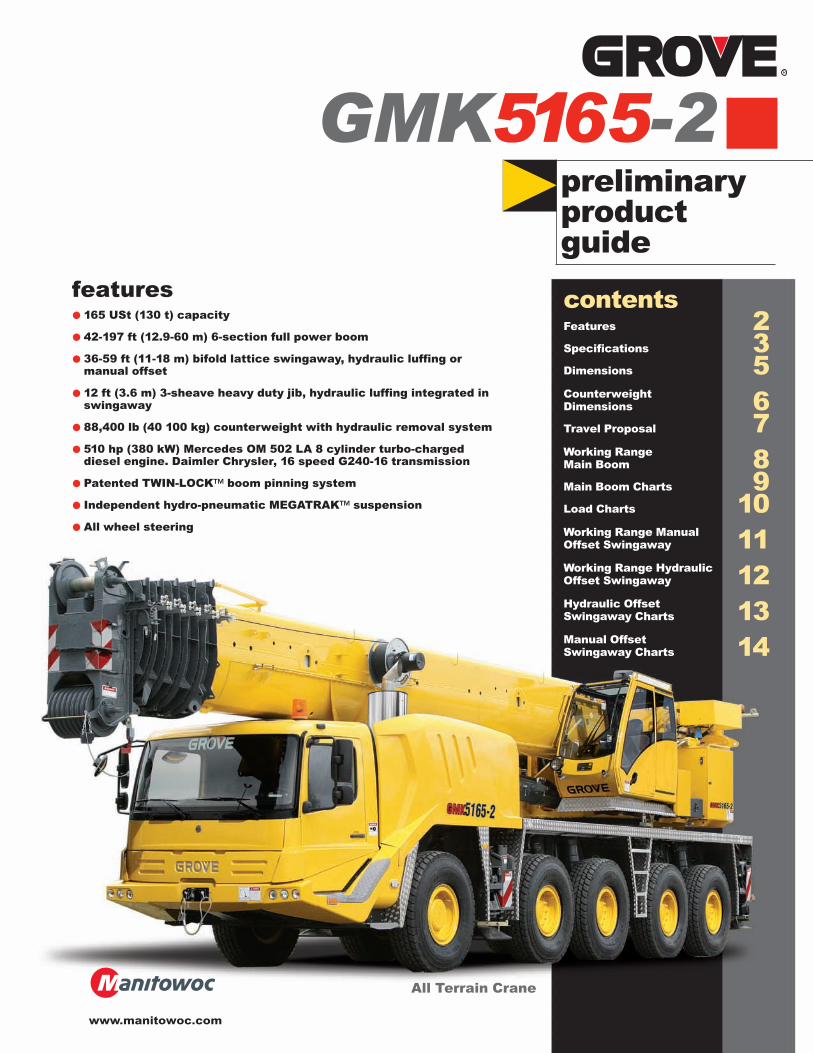
preliminary product guide features • 165 USt (130 t) capacity • 42-197 ft (12.9-60 m) 6-section full power boom • 36-59 ft (11-18 m) bifold lattice swingaway, hydraulic luffing or manual offset • 12 ft (3.6 m) 3-sheave heavy duty jib, hydraulic luffing integrated in swingaway • 88,400 lb (40 100 kg) counterweight with hydraulic removal system • 510 hp (380 kW) Mercedes OM 502 LA 8 cylinder turbo-charged diesel engine. Daimler Chrysler, 16 speed G240-16 transmission • Patented TWIN-LOCK™ boom pinning system • Independent hydro-pneumatic MEGATRAK™ suspension • All wheel steering GMK 5165 -2 All Terrain Crane contents Features 2 Specifications 3 Dimensions 5 Counterweight Dimensions 6 Travel Proposal 7 Working Range Main Boom 8 Main Boom Charts 9 Load Charts 10 Working Range Manual Offset Swingaway 11 Working Range Hydraulic Offset Swingaway 12 Hydraulic Offset Swingaway Charts 13 Manual Offset Swingaway Charts 14 www.manitowoc.com
Transcript of preliminary product guide - Gatwood Crane Service, Inc.GMK 51 65-2 specifications Superstructure...
preliminaryproductguide
features• 165 USt (130 t) capacity
• 42-197 ft (12.9-60 m) 6-section full power boom
• 36-59 ft (11-18 m) bifold lattice swingaway, hydraulic luffing ormanual offset
• 12 ft (3.6 m) 3-sheave heavy duty jib, hydraulic luffing integrated inswingaway
• 88,400 lb (40 100 kg) counterweight with hydraulic removal system
• 510 hp (380 kW) Mercedes OM 502 LA 8 cylinder turbo-chargeddiesel engine. Daimler Chrysler, 16 speed G240-16 transmission
• Patented TWIN-LOCK™ boom pinning system
• Independent hydro-pneumatic MEGATRAK™ suspension
• All wheel steering
GMK5165-2
All Terrain Crane
contentsFeatures 2Specifications 3Dimensions 5Counterweight Dimensions 6Travel Proposal 7Working RangeMain Boom 8Main Boom Charts 9Load Charts 10Working Range Manual Offset Swingaway 11Working Range Hydraulic Offset Swingaway 12Hydraulic OffsetSwingaway Charts 13Manual Offset Swingaway Charts 14
www.manitowoc.com
features
2
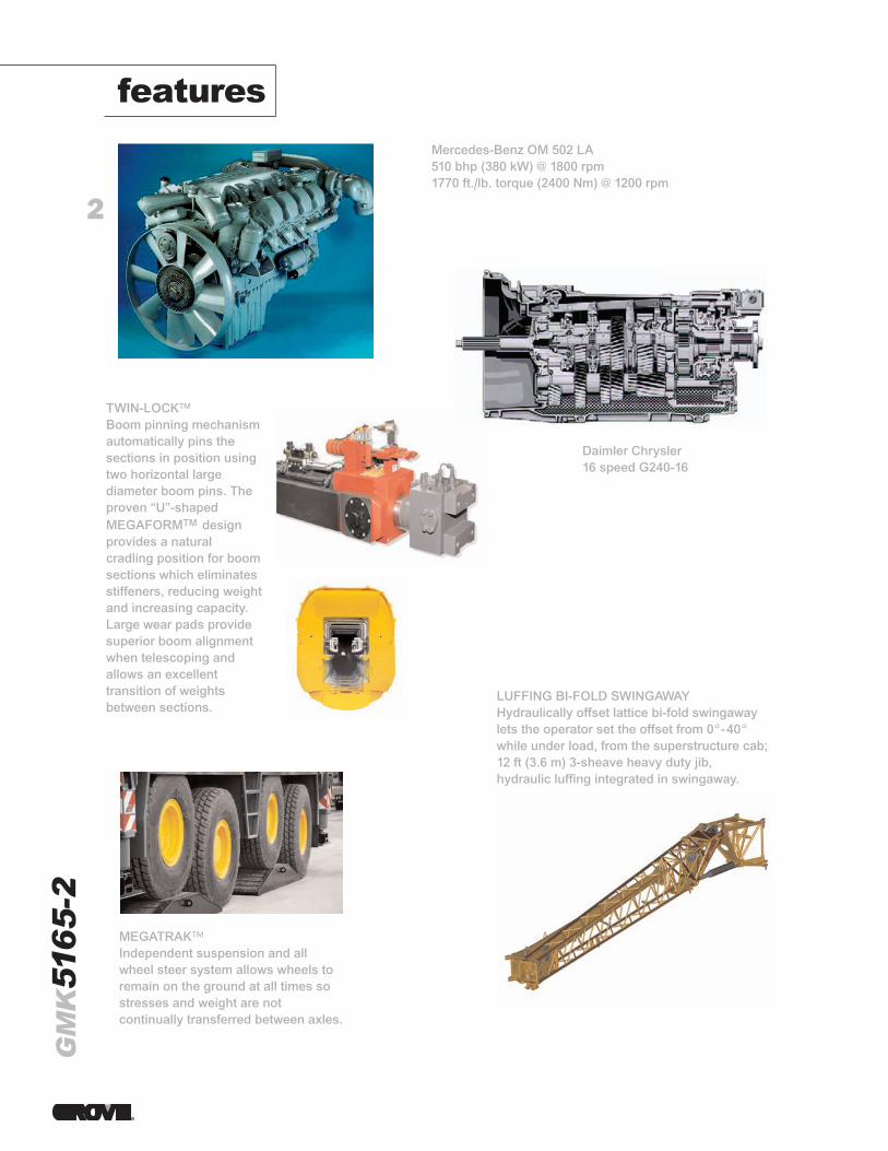
Mercedes-Benz OM 502 LA510 bhp (380 kW) @ 1800 rpm1770 ft./lb. torque (2400 Nm) @ 1200 rpm
Daimler Chrysler16 speed G240-16
TWIN-LOCK™ Boom pinning mechanismautomatically pins thesections in position usingtwo horizontal largediameter boom pins. Theproven “U”-shapedMEGAFORMTM designprovides a naturalcradling position for boomsections which eliminatesstiffeners, reducing weightand increasing capacity.Large wear pads providesuperior boom alignmentwhen telescoping andallows an excellenttransition of weightsbetween sections.
LUFFING BI-FOLD SWINGAWAYHydraulically offset lattice bi-fold swingawaylets the operator set the offset from 0°-40°while under load, from the superstructure cab;12 ft (3.6 m) 3-sheave heavy duty jib,hydraulic luffing integrated in swingaway.
MEGATRAK™Independent suspension and allwheel steer system allows wheels toremain on the ground at all times sostresses and weight are notcontinually transferred between axles.
GM
K51
65
-2
3
GM
K51
65
-2
specifications
Superstructure
Boom42 ft. - 197 ft. (12.9 m - 60 m) six section, full power boom withpatented TWIN-LOCK™ boom pinning system. Maximum tipheight: 207 ft. (63 m).
Boom NoseEight nylatron sheaves, mounted on heavy duty tapered rollerbearings with removable pin-type rope guards. Quick reeveboom nose. Removable auxiliary boom nose with removable pintype rope guard.
Boom ElevationSingle lift cylinder with safety valve provides boomangle from -3° to +83°.
Hydraulically Offsettable LatticeExtension
36 ft. – 59 ft. (11 m - 18 m) bifold lattice swingaway extensionhydraulically offsettable and luffing under load: 0° - 40°.Controlled from the crane cab. Maximum tip height: 266 ft. (81 m)
*Offsettable Lattice Extension36 ft. - 59 ft. (11 m - 18 m) bifold lattice swingaway extensionmanually offset: 0°, 20° or 40°. Maximum tip height: 266 ft. (81 m)
Lattice Extension InsertsOne 26 ft. (8 m) and one 20 ft. (6 m) insert for use with latticeswingaway extension. Increases extension length to 85 ft. (26 m)or 105 ft. (32 m).
Load Moment & Anti-Two BlockSystem
Load moment and anti-two block system with audio/visualwarning and control lever lockout provides electronic display ofboom angle, length, radius, tip height, relative load moment,maximum permissible load, load indication and warning ofimpending two-block condition.
CabAll aluminum construction cab with acoustical lining, tintedsafety glass, adjustable operator’s seat with suspension,opening windows in side and cab rear, hinged front window withwiper, sunvisor and window shade. Other features include hotwater heater, armrest integrated crane controls, andergonomically arranged instrumentation.
Crane Control SystemFull electronic control of all crane movements using electricalcontrol levers with automatic reset to zero. Controls areintegrated with the LMI and engine management system byCAN-BUS. ECOS system with graphic display.
SwingTwo planetary gears with axial piston motors. Infinitely variable to1.7 rpm. Holding and service brake.
Counterweight88,400 lbs. (40 100 kg) consisting of various sections withhydraulic installation/removal system. Controlled from thesuperstructure cab.
EngineMercedes-Benz OM 904 LA diesel, 4 cylinders, water cooled,turbocharged with 174 bhp (130 kW) @ 2200 rpm. Max torque: 498 ft/lb. (675 Nm) at 100 rpm. Engine emission: EUROMOT/EPA/CARB (non road).
Hydraulic System2 separate circuits, 1 axial piston variable displacement pump(load sensing) with electronic power limiting control and 1 gearpump for swing. Dual thermostatically controlled oil coolers keep oil at optimumoperating temperature.Tank capacity: 221 gal. (840 l)
HoistMain and auxiliary hoists are powered by axial piston motor withplanetary gear and brake. “Thumb-thumper” hoist drum rotationindicator alerts operator of hoist movement.
Main Auxiliary
Line length: 837 ft. 591 ft.(255 m) (180 m)
Rope diameter: 19 mm 19 mm
Line speed: 394 ft./min. 394 ft./min.(120 m/min) (120 m/min)
Line pull: 15,700 lbs. 15,700 lbs.(70 kN) (70 kN)
Electrical System24V system with three phase alternator, 28V/80A. 2 batteries,12V/170 Ah.
*Optional Equipment*11.8 ft (3.6 m) side-stowed 3-sheave heavy-duty jib integrated inswingaway.
*Work light, mounted on top of base section.*Cab controlled work lights mounted to top of base section.*Stainless steel exhaust system with spark arrestor in lieu ofstandard.
*Engine independent diesel cab heater, also serves as enginepreheater including 24-hour timer.
*Engine independent propane gas cab heater. *Stereo/radio CD player.*Outrigger pad load indicator with readout both in superstructurecab and carrier.
*Air conditioning.*Working range limiter.*Boom mounted aircraft warning light.*Drive and steer control for superstructure.*EKS5 with full graphic display.
*Denotes optional equipment
Boom
Boom Nose
Boom Elevation
Extension
Extension
Insert
Load Moment �& Anti-Two �Block System
�
Cab
Crane�Functions
Defined Arc
Counterweight
Engine
Hydraulic System
Hoist
Electrical System
4
GM
K51
65
-2specifications
Carrier
ChassisBox type, torsion resistant frame is fabricated from high strengthsteel.
Outrigger SystemFour hydraulic single stage outrigger beams with verticalcylinders and outrigger pads, 23.6” (600 mm) square.Outriggers can be set in 3 positions:
Full - 24.6' (7.5 m)Partial - 22.0' (6.7 m)
- 19.4’ (5.9 m)- 16.7’ (5.1m)
Retracted - 8.2' (2.5 m)
Independent horizontal and vertical movement controlled fromeach side of carrier. Electronic crane level indicators.
EngineMercedes-Benz OM 502 LA eight cylinder, water cooled, turbo-charged, with 510 bhp (380 kW) @ 1800 rpm. Max. torque 1,770ft./lb. (2 400 Nm) @ 1200 rpm. Engine emissions: EUROMOT/EPA/CARB (off road)Compression and exhaust brakes.
Fuel Tank Capacity106 gallons (400 L).
TransmissionDaimler Chrysler, 16 speed G240-16.
Drive/Steer10X6X10
Axles1st axle line – steer
2nd axle line – steer (additional drive)
3rd axle line – drive/steer (disconnects for highway travel10x8x10 drive only)
4th axle line – drive/steer (connects for all wheel steer)
5th axle line – drive/steer
Drive axles with planetary hub reduction and center mounteddifferential-gearing. Inter-axle and cross axle differential locks.
SuspensionExclusive MEGATRAK suspension. Independent hydro-pneumatic system acting on all wheels with hydraulic lockout.Suspension can be raised 6.5” (170 mm) or lowered 5” (130 mm)both longitudinally and transversely. Features an automaticleveling system for highway travel.
Tires10 tires, 16.00R25
SteeringDual circuit, hydraulic power assisted steering system. Transfercase mounted, ground driven emergency steering pump. Axles1, 2, 3 and 5 steer on highway. Separate steering of the 4th and5th axles for all wheel and crab steering, controlled by anelectronic rocker switch.
BrakesService brakes: pneumatic dual circuit acting on all wheels, antilock prevention. Parking brake: pneumatically operated spring loaded brakeacting on axle lines 2 and 5.Air dryer.
CabTwo-man construction with the following features: safety glass,driver and passenger seats with suspension, heated rear viewmirrors, engine independent diesel cab heater, AC, completeinstrumentation and driving controls.
Electrical System24V system with three phase alternator, 28V/100A2 batteries, 12V/170 Ah
Maximum Speed53 mph (85 kph)
Gradeability (Theoretical)72% - 14.00 tires64% - 16.00/20.5 tires
Miscellaneous Standard EquipmentWork light; tool kit; fire extinguisher; auxiliary boom nose;radio/CD player in carrier cab, heated rear view mirrors, andcruise control.
Optional Equipment*Stainless steel exhaust system with spark arrestor*20.5R25 tires (vehicle width 10.2 ft., 3.1 m)*10X8X10 drive/steer*Electric driveline retarder*Worklights for outriggers*Steel outrigger floats*Spare tire with carry bracket*Outrigger pad load indicator*Hinged bunk bed
*Denotes optional equipment
Frame
Outriggers
Engine
Fuel �Tank �Capacity
Transmission
Steering
Axles
Suspension
Tires
Steering
Brakes
Cab
Electrical System
Speed
Grade
5
GM
K51
65
-2
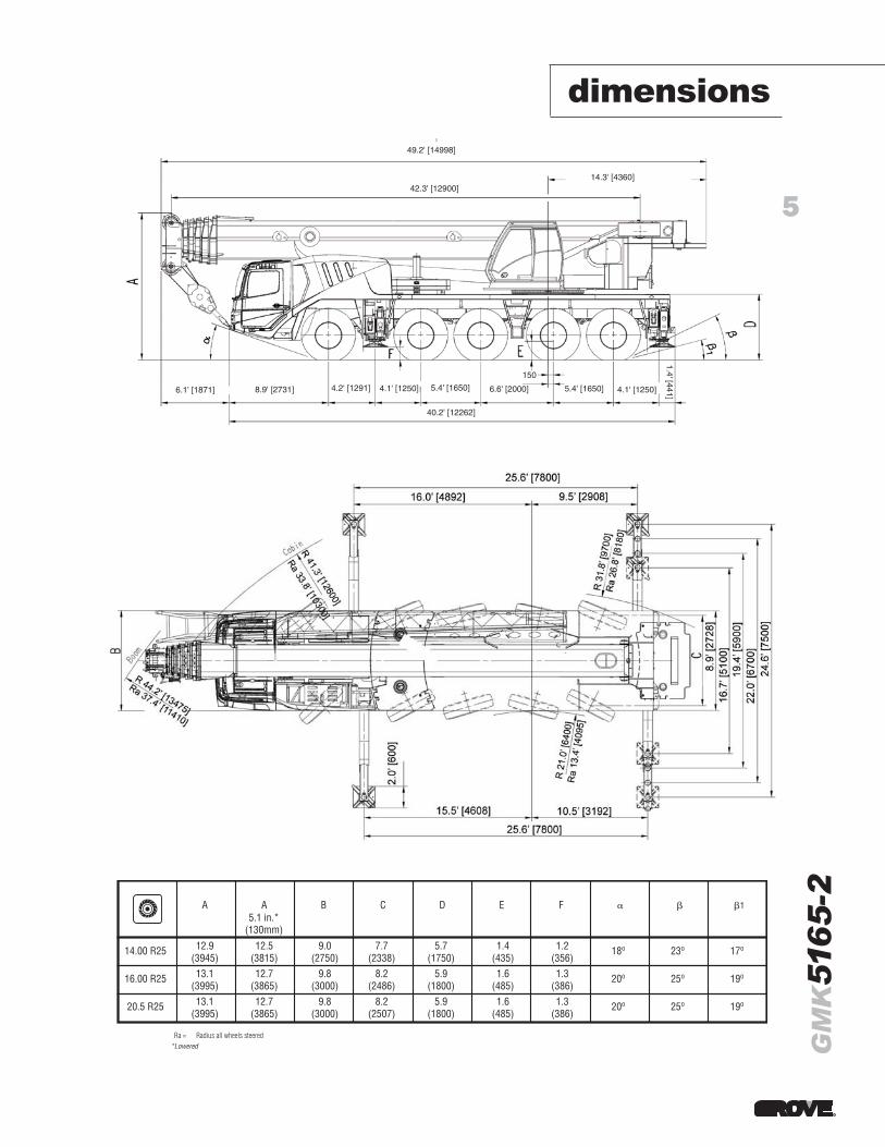
dimensions49.2' [14998]
40.2' [12262]
5.4' [1650] 4.1' [1250]6.6' [2000]
150
42.3' [12900]14.3' [4360]
1.4' [441]
5.4' [1650]4.1' [1250]4.2' [1291]8.9' [2731]6.1' [1871]
Ra = Radius all wheels steered
14.00 R25
A
12.9(3945)
A5.1 in.*
(130mm)12.5
(3815)
B
9.0(2750)
C
7.7(2338)
D
5.7(1750)
E
1.4(435)
F
1.2(356)
18o 23o
1
17o
16.00 R25 13.1(3995)
12.7(3865)
9.8(3000)
8.2(2486)
5.9(1800)
1.6(485)
1.3(386)
20o 25o 19o
20.5 R25 13.1(3995)
12.7(3865)
9.8(3000)
8.2(2507)
5.9(1800)
1.6(485)
1.3(386)
20o 25o 19o
*Lowered
6
GM
K51
65
-2
1
2
3 4
56
7
89
10 11
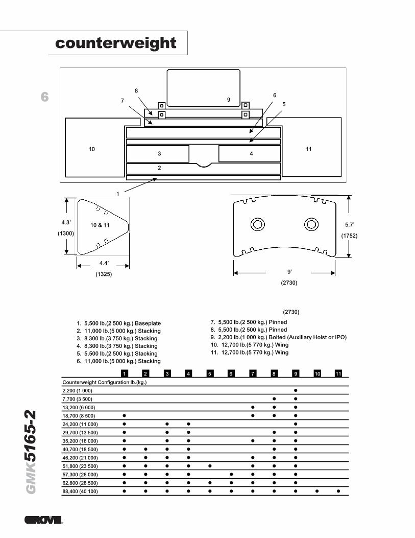
1. 5,500 lb.(2 500 kg.) Baseplate2. 11,000 lb.(5 000 kg.) Stacking3. 8 300 lb.(3 750 kg.) Stacking4. 8,300 lb.(3 750 kg.) Stacking5. 5,500 lb.(2 500 kg.) Stacking6. 11,000 lb.(5 000 kg.) Stacking
7. 5,500 lb.(2 500 kg.) Pinned8. 5,500 lb.(2 500 kg.) Pinned9. 2,200 lb.(1 000 kg.) Bolted (Auxiliary Hoist or IPO)10. 12,700 lb.(5 770 kg.) Wing11. 12,700 lb.(5 770 kg.) Wing
10 & 114.3’
(1300)
4.4’
(1325)
5.7’
(1752)
9’
(2730)
Counterweight Configuration lb.(kg.)
2,200 (1 000)
7,700 (3 500)
13,200 (6 000)
18,700 (8 500)
24,200 (11 000)
29,700 (13 500)
35,200 (16 000)
40,700 (18 500)
46,200 (21 000)
51,800 (23 500)
57,300 (26 000)
62,800 (28 500)
88,400 (40 100)
1
2
3 4
56
7
89
10 11
1. 5,500 lb.(2 500 kg.) Baseplate2. 11,000 lb.(5 000 kg.) Stacking3. 8 300 lb.(3 750 kg.) Stacking4. 8,300 lb.(3 750 kg.) Stacking5. 5,500 lb.(2 500 kg.) Stacking6. 11,000 lb.(5 000 kg.) Stacking
7. 5,500 lb.(2 500 kg.) Pinned8. 5,500 lb.(2 500 kg.) Pinned9. 2,200 lb.(1 000 kg.) Bolted (Auxiliary Hoist or IPO)10. 12,700 lb.(5 770 kg.) Wing11. 12,700 lb.(5 770 kg.) Wing
10 & 114.3’
(1300)
4.4’
(1325)
5.7’
(1752)
9’
(2730)
Counterweight Configuration lb.(kg.)
2,200 (1 000)
7,700 (3 500)
13,200 (6 000)
18,700 (8 500)
24,200 (11 000)
29,700 (13 500)
35,200 (16 000)
40,700 (18 500)
46,200 (21 000)
51,800 (23 500)
57,300 (26 000)
62,800 (28 500)
88,400 (40 100)
counterweight
7
GM
K51
65
-2
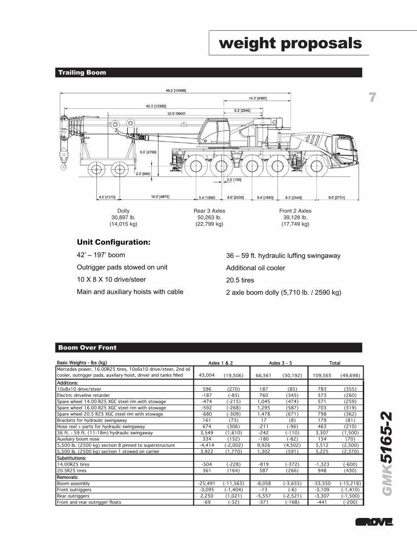
Trailing Boom
Boom Over Front
Unit Configuration:42’ – 197’ boom
Outrigger pads stowed on unit
10 X 8 X 10 drive/steer
Main and auxiliary hoists with cable
36 – 59 ft. hydraulic luffing swingaway
Additional oil cooler
20.5 tires
2 axle boom dolly (5,710 lb. / 2590 kg)
weight proposals
BBaassiicc WWeeiigghhttss -- llbbss ((kkgg))Mercedes power, 16.00R25 tires, 10x6x10 drive/steer, 2nd oil cooler, outrigger pads, auxiliary hoist, driver and tanks filled 43,004 (19,506) 66,561 (30,192) 109,565 (49,698)AAddddiittiioonnss::10x8x10 drive/steer 596 (270) 187 (85) 783 (355)Electric driveline retarder -187 (-85) 760 (345) 573 (260)Spare wheel 14.00 R25 XGC steel rim with stowage -474 (-215) 1,045 (474) 571 (259)Spare wheel 16.00 R25 XGC steel rim with stowage -592 (-268) 1,295 (587) 703 (319)Spare wheel 20.5 R25 XGC steel rim with stowage -680 (-309) 1,478 (671) 798 (362)Brackets for hydraulic swingaway 161 (73) 17 (8) 179 (81)Hose reel + parts for hydraulic swingaway 674 (306) -211 (-96) 463 (210)36 ft. - 59 ft. (11-18m) hydraulic swingaway 3,549 (1,610) -242 (-110) 3,307 (1,500)Auxiliary boom nose 334 (152) -180 (-82) 154 (70)5,500 lb. (2500 kg) section 8 pinned to superstructure -4,414 (-2,002) 9,926 (4,502) 5,512 (2,500)5,500 lb. (2500 kg) section 1 stowed on carrier 3,922 (1,770) 1,302 (591) 5,225 (2,370)SSuubbssttiittuuttiioonnss::14.00R25 tires -504 (-228) -819 (-372) -1,323 (-600)20.5R25 tires 361 (164) 587 (266) 948 (430)RReemmoovvaallss::Boom assembly -25,491 (-11,563) -8,058 (-3,655) -33,550 (-15,218)Front outriggers -3,095 (-1,404) -13 (-6) -3,109 (-1,410)Rear outriggers 2,250 (1,021) -5,557 (-2,521) -3,307 (-1,500)Front and rear outrigger floats -69 (-32) -371 (-168) -441 (-200)
AAxxlleess 11 && 22 AAxxlleess 33 -- 55 TToottaall
Dolly Rear 3 Axles Front 2 Axles30,897 lb. 50,263 lb. 39,128 lb.
(14,015 kg) (22,799 kg) (17,749 kg)
8
GM
K51
65
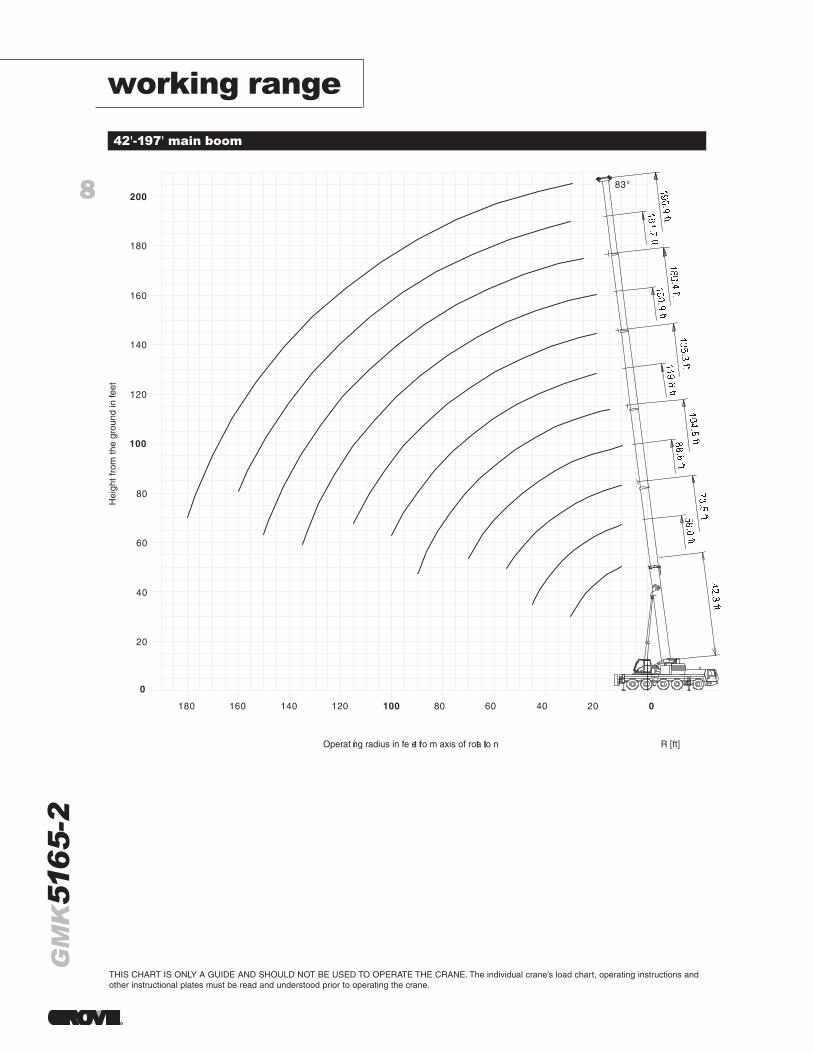
-2working range
R [ft]
180 160 140 120 100 80 60 40 20 0
20
0
40
60
80
100
120
140
160
180
200 83°
Operat ing radius in fe et fro m axis of rota tio n
Hei
ght f
rom
the
grou
nd in
feet
42'-197' main boom
THIS CHART IS ONLY A GUIDE AND SHOULD NOT BE USED TO OPERATE THE CRANE. The individual crane’s load chart, operating instructions andother instructional plates must be read and understood prior to operating the crane.
9
GM
K51
65
-2
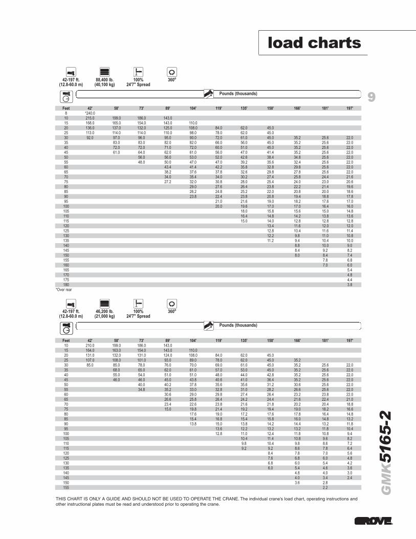
load charts
THIS CHART IS ONLY A GUIDE AND SHOULD NOT BE USED TO OPERATE THE CRANE. The individual crane’s load chart, operating instructions andother instructional plates must be read and understood prior to operating the crane.
Boom Counterweight Outriggers Defined Arc
42-197 ft.(12.8-60.0 m)
88,400 lb.(40,100 kg)
100%24'7" Spread
360o
Pounds (thousands)Radius
Feet 42' 58' 73' 89' 104' 119' 135' 150' 166' 181' 197'8 *240.0
10 215.0 199.0 186.0 143.015 168.0 165.0 154.0 143.0 110.020 136.0 137.0 132.0 125.0 108.0 84.0 62.0 45.025 113.0 114.0 114.0 110.0 98.0 78.0 62.0 45.030 92.0 97.0 96.0 95.0 90.0 72.0 61.0 45.0 35.2 25.6 22.035 83.0 83.0 82.0 82.0 66.0 56.0 45.0 35.2 25.6 22.040 72.0 72.0 71.0 72.0 60.0 51.0 45.0 35.2 25.6 22.045 61.0 64.0 62.0 61.0 56.0 47.0 41.4 35.2 25.6 22.050 56.0 56.0 53.0 52.0 42.6 38.4 34.8 25.6 22.055 48.0 50.0 47.0 47.0 39.2 35.6 32.4 25.6 22.060 43.4 41.4 42.2 35.8 32.8 29.8 25.6 22.065 38.2 37.6 37.8 32.6 29.8 27.8 25.6 22.070 34.0 35.4 34.0 30.2 27.4 25.8 24.4 21.675 27.2 32.0 30.8 28.0 25.4 24.0 23.0 20.680 29.0 27.6 26.4 23.8 22.2 21.4 19.685 26.2 24.8 25.2 22.0 20.8 20.0 18.690 23.8 22.4 23.8 20.8 19.4 18.8 17.895 21.0 21.6 19.0 18.2 17.6 17.0100 20.0 19.6 17.0 17.0 16.4 16.0105 18.0 15.8 15.6 15.0 14.8110 16.4 14.8 14.2 13.8 13.6115 15.0 14.0 12.8 12.8 12.8120 13.4 11.6 12.0 12.0125 12.8 10.4 11.6 11.4130 12.2 9.8 11.0 10.8135 11.2 9.4 10.4 10.0140 8.8 10.0 9.0145 8.4 9.2 8.2150 8.0 8.4 7.4155 7.8 6.8160 7.0 6.0165 5.4170 4.8175 4.4180 3.8
*Over rear
Feet 42' 58' 73' 89' 104' 119' 135' 150' 166' 181' 197'10 210.0 199.0 186.0 143.015 164.0 163.0 154.0 143.0 110.020 131.0 132.0 131.0 124.0 108.0 84.0 62.0 45.025 107.0 108.0 101.0 93.0 89.0 78.0 62.0 45.0 35.230 85.0 85.0 78.0 76.0 70.0 69.0 61.0 45.0 35.2 25.6 22.035 68.0 65.0 62.0 61.0 57.0 53.0 45.0 35.2 25.6 22.040 55.0 54.0 51.0 51.0 48.0 44.0 42.8 35.2 25.6 22.045 46.0 46.0 45.0 43.8 40.6 41.0 36.4 35.2 25.6 22.050 40.0 40.2 37.8 35.6 35.6 31.2 30.6 25.6 22.055 34.8 35.2 33.0 32.8 31.0 28.2 26.6 25.6 22.060 30.6 29.0 29.8 27.4 26.4 23.2 23.8 22.065 26.6 25.8 26.4 24.2 24.4 21.6 22.4 21.070 23.4 22.6 23.8 21.6 21.8 20.2 20.4 18.875 15.0 19.8 21.4 19.2 19.4 19.0 18.2 16.680 17.6 19.0 17.2 17.6 17.8 16.4 14.885 15.4 16.8 15.4 15.8 16.0 14.8 13.290 13.8 15.0 13.8 14.2 14.4 13.2 11.895 13.6 12.2 13.2 13.2 11.8 10.4
100 12.8 11.0 12.4 11.8 10.8 9.4105 10.4 11.4 10.8 9.6 8.2110 9.8 10.4 9.8 8.6 7.2115 9.2 9.2 8.6 7.8 6.4120 8.4 7.8 7.0 5.6125 7.6 6.8 6.0 4.8130 6.8 6.0 5.4 4.2135 6.0 5.4 4.6 3.6140 4.8 4.0 3.0145 4.0 3.4 2.4150 3.6 2.8155 2.2
Boom Counterweight Outriggers Defined Arc
42-197 ft.(12.8-60.0 m)
46,200 lb.(21,000 kg)
100%24'7" Spread
360o
Pounds (thousands)Boom�Radius
Boom Extension
Boom Extension
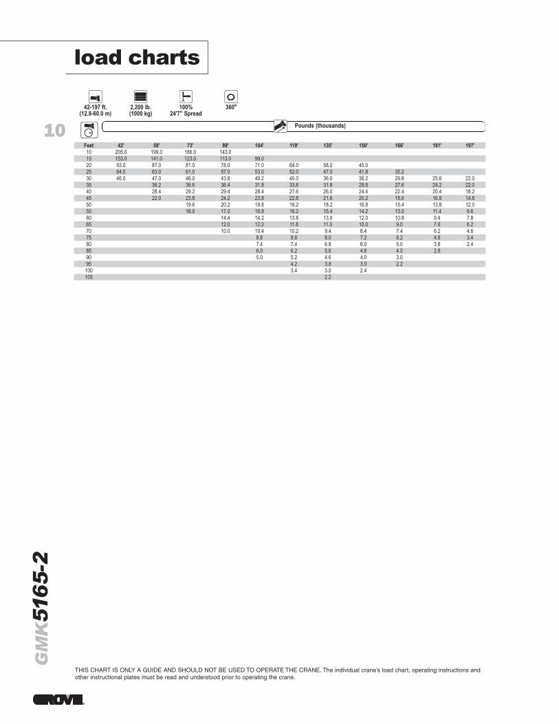
THIS CHART IS ONLY A GUIDE AND SHOULD NOT BE USED TO OPERATE THE CRANE. The individual crane’s load chart, operating instructions andother instructional plates must be read and understood prior to operating the crane.
10
GM
K51
65
-2load charts
Boom Counterweight Outriggers Defined Arc
42-197 ft.(12.8-60.0 m)
2,200 lb.(1000 kg)
100%24'7" Spread
360o
Pounds (thousands)Radius Boom Extension
Feet 42' 58' 73' 89' 104' 119' 135' 150' 166' 181' 197'10 205.0 199.0 186.0 143.015 153.0 141.0 123.0 113.0 99.020 93.0 87.0 81.0 78.0 71.0 64.0 58.0 45.025 64.0 63.0 61.0 57.0 53.0 52.0 47.0 41.8 35.230 46.0 47.0 46.0 43.8 40.2 40.0 36.0 36.2 29.8 25.6 22.035 36.2 36.6 36.4 31.8 33.8 31.8 29.8 27.6 24.2 22.040 28.4 29.2 29.4 28.4 27.6 26.0 24.4 22.4 20.4 18.245 22.0 23.8 24.2 23.8 22.8 21.6 20.2 18.6 16.8 14.850 19.6 20.2 19.8 19.2 18.2 16.8 15.4 13.8 12.055 16.0 17.0 16.8 16.2 15.4 14.2 13.0 11.4 9.660 14.4 14.2 13.8 13.0 12.0 10.8 9.4 7.865 12.0 12.2 11.8 11.0 10.0 9.0 7.6 6.270 10.0 10.4 10.2 9.4 8.4 7.4 6.2 4.675 8.8 8.6 8.0 7.2 6.2 4.8 3.480 7.4 7.4 6.8 6.0 5.0 3.8 2.485 6.0 6.2 5.6 4.8 4.0 2.890 5.0 5.2 4.6 4.0 3.095 4.2 3.8 3.0 2.2100 3.4 3.0 2.4105 2.2
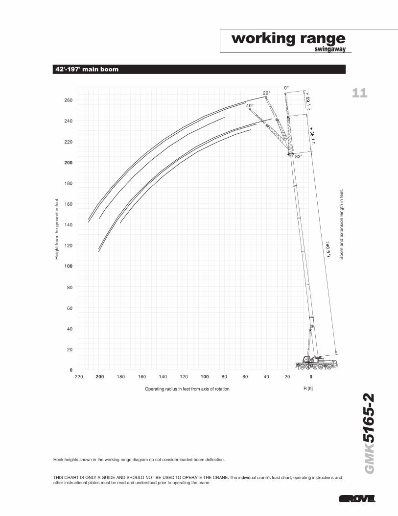
working rangeswingaway
11
GM
K51
65
-2
THIS CHART IS ONLY A GUIDE AND SHOULD NOT BE USED TO OPERATE THE CRANE. The individual crane’s load chart, operating instructions andother instructional plates must be read and understood prior to operating the crane.
42'-197' main boom
20
220 200 180 160 140 120 100 80 60 40 20 0 0
40
60
80
100
120
140
160
180
200
220
240
260
0° 20°
40°
83°
1 - 34 3 109 320 en GMK 5130-1
R [ft] Operating radius in feet from axis of rotation
Hei
ght f
rom
the
grou
nd in
feet
Boo
m a
nd e
xten
sion
leng
th in
feet
.
Hook heights shown in the working range diagram do not consider loaded boom deflection.
12
GM
K51
65
-2
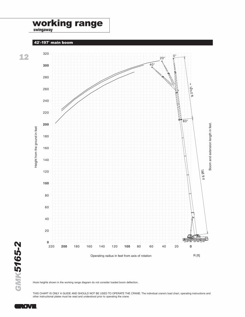
42'-197' main boom
working rangeswingaway
THIS CHART IS ONLY A GUIDE AND SHOULD NOT BE USED TO OPERATE THE CRANE. The individual crane’s load chart, operating instructions andother instructional plates must be read and understood prior to operating the crane.
R [ft]
20
220 200 180 160 140 120 100 80 60 40 20 0 0
40
60
80
100
120
140
160
180
200
220
240
260
280
300
320 0°
20°
40°
83°
Operating radius in feet from axis of rotation
Hei
ght f
rom
the
grou
nd in
feet
Boo
m a
nd e
xten
sion
leng
th in
feet
.
Hook heights shown in the working range diagram do not consider loaded boom deflection.
13
GM
K51
65
-2
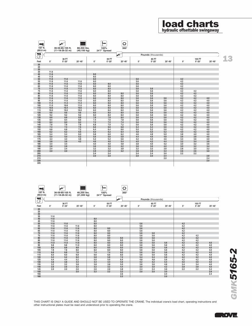
load chartshydraulic offsettable swingaway
Radius Pounds (thousands)AmericanSwingaway
36 FT 59 FT 85 FT 105 FTFeet 0° 0°-20° 20°-40° 0° 0°-20° 20°-40° 0° 0°-20° 20°-40° 0° 0°-20° 20°-40°20253035 11.640 11.6 8.045 11.6 8.050 11.6 11.6 8.0 5.6 4.255 11.6 11.6 11.6 8.0 5.6 4.260 11.6 11.6 11.6 8.0 8.0 5.6 4.265 11.6 11.6 11.6 8.0 8.0 5.6 4.270 11.6 11.6 11.6 8.0 8.0 5.6 5.6 4.275 11.6 11.6 11.6 8.0 8.0 5.6 5.6 4.2 4.280 11.6 11.6 11.6 8.0 8.0 8.0 5.6 5.6 4.2 4.285 11.6 11.6 11.6 8.0 8.0 8.0 5.6 5.6 4.2 4.290 11.0 11.0 11.6 8.0 8.0 8.0 5.6 5.6 5.6 4.2 4.2 4.095 9.8 9.8 11.0 8.0 8.0 8.0 5.6 5.6 5.6 4.2 4.2 4.0
100 8.8 8.8 9.8 8.0 8.0 8.0 5.6 5.6 5.6 4.2 4.2 4.0105 7.8 7.8 8.6 8.0 8.0 8.0 5.6 5.6 5.6 4.2 4.2 4.0110 6.8 6.8 7.6 7.4 7.4 8.0 5.6 5.6 5.6 4.2 4.2 4.0115 6.0 6.0 6.8 6.6 6.6 8.0 5.6 5.6 5.6 4.2 4.2 4.0120 5.2 5.2 6.0 5.8 5.8 7.2 5.4 5.4 5.6 4.2 4.2 4.0125 4.4 4.4 5.2 5.0 5.0 6.4 4.8 4.8 5.6 4.2 4.2 4.0130 3.8 3.8 4.4 4.4 4.4 5.6 4.2 4.2 5.4 4.0 4.0 4.0135 3.2 3.2 3.8 3.8 3.8 5.0 3.6 3.6 4.8 3.4 3.4 4.0140 2.6 2.6 3.2 3.2 3.2 4.4 3.0 3.0 4.2 2.8 2.8 4.0145 2.0 2.0 2.6 2.6 2.6 3.8 2.4 2.4 3.6 2.2 2.2 3.4150 2.0 2.2 2.2 3.2 2.0 2.0 3.0 2.8155 2.6 2.4 2.4160 2.2 2.0
Boom AmericanSwingaway
Counterweight Outriggers
197 ft.(60.0 m)
36-59-85-105 ft.(11-18-26-32 m)
46,200 lbs.(21,000 kg)
100%24'7" Spread
Rotation
360°
Radius Pounds (thousands)AmericanSwingaway
36 FT 59 FT 85 FT 105 FTFeet 0° 0°-20° 20°-40° 0° 0°-20° 20°-40° 0° 0°-20° 20°-40° 0° 0°-20° 20°-40°20253035 11.640 11.6 8.045 11.6 8.050 11.6 11.6 8.0 5.6 4.255 11.6 11.6 11.6 8.0 5.6 4.260 11.6 11.6 11.6 8.0 8.0 5.6 4.265 11.6 11.6 11.6 8.0 8.0 5.6 4.270 11.6 11.6 11.6 8.0 8.0 5.6 5.6 4.275 11.6 11.6 11.6 8.0 8.0 5.6 5.6 4.2 4.280 11.6 11.6 11.6 8.0 8.0 8.0 5.6 5.6 4.2 4.285 11.6 11.6 11.6 8.0 8.0 8.0 5.6 5.6 4.2 4.290 11.6 11.6 11.6 8.0 8.0 8.0 5.6 5.6 5.6 4.2 4.2 4.095 11.6 11.6 11.6 8.0 8.0 8.0 5.6 5.6 5.6 4.2 4.2 4.0
100 11.4 11.4 11.4 8.0 8.0 8.0 5.6 5.6 5.6 4.2 4.2 4.0105 11.0 10.8 11.0 8.0 8.0 8.0 5.6 5.6 5.6 4.2 4.2 4.0110 10.6 10.4 10.6 8.0 8.0 8.0 5.6 5.6 5.6 4.2 4.2 4.0115 10.0 10.0 10.0 8.0 8.0 8.0 5.6 5.6 5.6 4.2 4.2 4.0120 9.6 9.6 9.6 8.0 8.0 8.0 5.6 5.6 5.6 4.2 4.2 4.0125 9.2 9.2 9.2 8.0 8.0 8.0 5.6 5.6 5.6 4.2 4.2 4.0130 8.8 8.8 8.8 7.8 7.8 8.0 5.6 5.6 5.6 4.2 4.2 4.0135 8.4 8.4 8.6 7.4 7.6 7.8 5.6 5.6 5.6 4.2 4.2 4.0140 8.0 8.0 8.2 7.2 7.2 7.4 5.6 5.6 5.6 4.2 4.2 4.0145 7.8 7.8 7.8 6.8 7.0 7.2 5.6 5.6 5.6 4.2 4.2 4.0150 7.4 7.4 7.6 6.6 6.6 6.8 5.4 5.4 5.6 4.2 4.2 4.0155 6.8 6.8 7.2 6.4 6.4 6.6 5.0 5.2 5.6 4.2 4.2 4.0160 6.2 6.2 6.6 6.0 6.2 6.4 4.8 5.0 5.2 4.0 4.2 4.0165 5.4 5.4 6.0 5.8 6.0 6.2 4.6 4.8 5.0 3.8 4.0 4.0170 5.0 5.0 5.2 5.6 5.6 5.8 4.4 4.6 4.8 3.6 3.8 4.0175 4.4 4.4 4.8 5.2 5.2 5.6 4.2 4.4 4.6 3.4 3.6 4.0180 3.8 3.8 4.2 4.6 4.6 5.4 4.0 4.2 4.4 3.2 3.4 3.8185 3.4 3.4 4.0 4.0 4.8 3.8 4.0 4.2 3.0 3.2 3.6190 2.8 2.8 3.6 3.6 4.2 3.6 3.6 4.0 3.0 3.2 3.4195 2.4 2.4 3.2 3.2 3.8 3.2 3.2 3.8 2.8 3.0 3.2200 2.0 2.0 2.8 2.8 3.2 2.8 2.8 3.4 2.6 2.6 3.0205 2.4 2.4 2.4 2.4 3.0 2.2 2.2210 2.0 2.0 2.0 2.0 2.4 2.8215 2.0 2.4220 2.0225
Boom AmericanSwingaway
Counterweight Outriggers
197 ft.(60.0 m)
36-59-85-105 ft.(11-18-26-32 m)
88,400 lbs.(40,100 kg)
100%24'7" Spread
Rotation
360°
THIS CHART IS ONLY A GUIDE AND SHOULD NOT BE USED TO OPERATE THE CRANE. The individual crane’s load chart, operating instructions andother instructional plates must be read and understood prior to operating the crane.
14
GM
K51
65
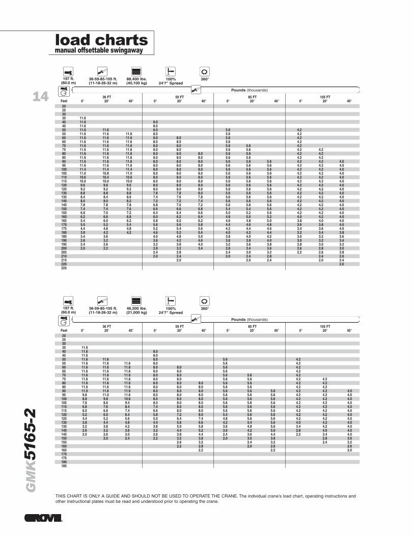
-2load chartsmanual offsettable swingaway
THIS CHART IS ONLY A GUIDE AND SHOULD NOT BE USED TO OPERATE THE CRANE. The individual crane’s load chart, operating instructions andother instructional plates must be read and understood prior to operating the crane.
Radius Pounds (thousands)AmericanSwingaway
36 FT 59 FT 85 FT 105 FTFeet 0° 20° 40° 0° 20° 40° 0° 20° 40° 0° 20° 40°20253035 11.640 11.6 8.045 11.6 8.050 11.6 11.6 8.0 5.6 4.255 11.6 11.6 11.6 8.0 5.6 4.260 11.6 11.6 11.6 8.0 8.0 5.6 4.265 11.6 11.6 11.6 8.0 8.0 5.6 4.270 11.6 11.6 11.6 8.0 8.0 5.6 5.6 4.275 11.6 11.6 11.6 8.0 8.0 5.6 5.6 4.2 4.280 11.6 11.6 11.6 8.0 8.0 8.0 5.6 5.6 4.2 4.285 11.6 11.6 11.6 8.0 8.0 8.0 5.6 5.6 4.2 4.290 11.6 11.6 11.6 8.0 8.0 8.0 5.6 5.6 5.6 4.2 4.2 4.095 11.6 11.6 11.6 8.0 8.0 8.0 5.6 5.6 5.6 4.2 4.2 4.0
100 11.4 11.4 11.4 8.0 8.0 8.0 5.6 5.6 5.6 4.2 4.2 4.0105 11.0 10.8 11.0 8.0 8.0 8.0 5.6 5.6 5.6 4.2 4.2 4.0110 10.6 10.4 10.6 8.0 8.0 8.0 5.6 5.6 5.6 4.2 4.2 4.0115 10.0 10.0 10.0 8.0 8.0 8.0 5.6 5.6 5.6 4.2 4.2 4.0120 9.6 9.6 9.6 8.0 8.0 8.0 5.6 5.6 5.6 4.2 4.2 4.0125 9.2 9.2 9.2 8.0 8.0 8.0 5.6 5.6 5.6 4.2 4.2 4.0130 8.8 8.8 8.8 7.8 7.8 8.0 5.6 5.6 5.6 4.2 4.2 4.0135 8.4 8.4 8.6 7.4 7.6 7.8 5.6 5.6 5.6 4.2 4.2 4.0140 8.0 8.0 8.2 7.2 7.2 7.4 5.6 5.6 5.6 4.2 4.2 4.0145 7.8 7.8 7.8 6.8 7.0 7.2 5.6 5.6 5.6 4.2 4.2 4.0150 7.4 7.4 7.6 6.6 6.6 6.8 5.4 5.4 5.6 4.2 4.2 4.0155 6.8 7.0 7.2 6.4 6.4 6.6 5.0 5.2 5.6 4.2 4.2 4.0160 6.2 6.6 6.8 6.0 6.2 6.4 4.8 5.0 5.2 4.0 4.2 4.0165 5.4 6.0 6.2 5.8 6.0 6.2 4.6 4.8 5.0 3.8 4.0 4.0170 5.0 5.2 5.4 5.6 5.6 5.8 4.4 4.6 4.8 3.6 3.8 4.0175 4.4 4.8 4.8 5.2 5.4 5.6 4.2 4.4 4.6 3.4 3.6 4.0180 3.8 4.2 4.2 4.6 5.2 5.4 4.0 4.2 4.4 3.2 3.4 3.8185 3.4 3.6 4.0 4.8 5.0 3.8 4.0 4.2 3.0 3.2 3.6190 2.8 3.2 3.6 4.2 4.6 3.6 3.8 4.0 3.0 3.2 3.4195 2.4 2.6 3.2 3.8 4.0 3.2 3.6 3.8 2.8 3.0 3.2200 2.0 2.2 2.8 3.2 3.4 2.8 3.4 3.6 2.6 2.8 3.0205 2.4 2.8 2.4 3.0 3.2 2.2 2.6 2.8210 2.0 2.4 2.0 2.4 2.8 2.4 2.6215 2.0 2.0 2.4 2.0 2.4220 2.0225
Boom AmericanSwingaway
Counterweight Outriggers
197 ft.(60.0 m)
36-59-85-105 ft.(11-18-26-32 m)
88,400 lbs.(40,100 kg)
100%24'7" Spread
Rotation
360°
Radius Pounds (thousands)AmericanSwingaway
36 FT 59 FT 85 FT 105 FTFeet 0° 20° 40° 0° 20° 40° 0° 20° 40° 0° 20° 40°20253035 11.640 11.6 8.045 11.6 8.050 11.6 11.6 8.0 5.6 4.255 11.6 11.6 11.6 8.0 5.6 4.260 11.6 11.6 11.6 8.0 8.0 5.6 4.265 11.6 11.6 11.6 8.0 8.0 5.6 4.270 11.6 11.6 11.6 8.0 8.0 5.6 5.6 4.275 11.6 11.6 11.6 8.0 8.0 5.6 5.6 4.2 4.280 11.6 11.6 11.6 8.0 8.0 8.0 5.6 5.6 4.2 4.285 11.6 11.6 11.6 8.0 8.0 8.0 5.6 5.6 4.2 4.290 11.0 11.6 11.6 8.0 8.0 8.0 5.6 5.6 5.6 4.2 4.2 4.095 9.8 11.0 11.6 8.0 8.0 8.0 5.6 5.6 5.6 4.2 4.2 4.0100 8.8 9.8 10.6 8.0 8.0 8.0 5.6 5.6 5.6 4.2 4.2 4.0105 7.8 8.6 9.4 8.0 8.0 8.0 5.6 5.6 5.6 4.2 4.2 4.0110 6.8 7.6 8.4 7.4 8.0 8.0 5.6 5.6 5.6 4.2 4.2 4.0115 6.0 6.8 7.4 6.6 8.0 8.0 5.6 5.6 5.6 4.2 4.2 4.0120 5.2 6.0 6.4 5.8 7.2 8.0 5.4 5.6 5.6 4.2 4.2 4.0125 4.4 5.2 5.6 5.0 6.4 7.4 4.8 5.6 5.6 4.2 4.2 4.0130 3.8 4.4 4.8 4.4 5.6 6.6 4.2 5.4 5.6 4.0 4.2 4.0135 3.2 3.8 4.2 3.8 5.0 5.8 3.6 4.8 5.6 3.4 4.2 4.0140 2.6 3.2 3.6 3.2 4.4 5.2 3.0 4.2 5.0 2.8 4.0 4.0145 2.0 2.6 3.0 2.6 3.8 4.4 2.4 3.6 4.4 2.2 3.4 4.0150 2.0 2.4 2.2 3.2 3.8 2.0 3.0 3.8 2.8 3.6155 2.6 3.2 2.4 3.2 2.4 3.2160 2.2 2.8 2.0 2.6 2.6165 2.2 2.2 2.0170175180185
Boom AmericanSwingaway
Counterweight Outriggers
197 ft.(60.0 m)
36-59-85-105 ft.(11-18-26-32 m)
46,200 lbs.(21,000 kg)
100%24'7" Spread
Rotation
360°