Preliminary power train design for a state-of-the-art electric vehicle
145
General Disclaimer One or more of the Following Statements may affect this Document This document has been reproduced from the best copy furnished by the organizational source. It is being released in the interest of making available as much information as possible. This document may contain data, which exceeds the sheet parameters. It was furnished in this condition by the organizational source and is the best copy available. This document may contain tone-on-tone or color graphs, charts and/or pictures, which have been reproduced in black and white. This document is paginated as submitted by the original source. Portions of this document are not fully legible due to the historical nature of some of the material. However, it is the best reproduction available from the original submission. Produced by the NASA Center for Aerospace Information (CASI) https://ntrs.nasa.gov/search.jsp?R=19780022049 2018-02-05T13:55:53+00:00Z
Transcript of Preliminary power train design for a state-of-the-art electric vehicle

General Disclaimer
One or more of the Following Statements may affect this Document
This document has been reproduced from the best copy furnished by the
organizational source. It is being released in the interest of making available as
much information as possible.
This document may contain data, which exceeds the sheet parameters. It was
furnished in this condition by the organizational source and is the best copy
available.
This document may contain tone-on-tone or color graphs, charts and/or pictures,
which have been reproduced in black and white.
This document is paginated as submitted by the original source.
Portions of this document are not fully legible due to the historical nature of some
of the material. However, it is the best reproduction available from the original
submission.
Produced by the NASA Center for Aerospace Information (CASI)
https://ntrs.nasa.gov/search.jsp?R=19780022049 2018-02-05T13:55:53+00:00Z

Ti
DOE/NASA/0595-78/1NASA CR-135341
PRELIMINARY POWER TRAIN DESIGN
FOR A STATE-OF-THE-ART
ELECTRIC VEHICLE
Phillip Mighdoll andWilliam F. HahnDesign and Development DivisionBOOZ, ALLEN 6 HAMILTON Inc.
April, 1978
Prepared for
NATIONAL AERONAUTICS AND SPACE ADMINISTRATIONLewis Research CenterUnder Contract NAS 3-20595
fo r
U.S. DEPARTMENT OF ENERGYElectric and Hybrid Vehicle Systems ProgramDivision of Transportation Energy Conservation
(NASA-CR-135341) PRELI41NARY POWER TRAIN N78-29992DESIGN FOR A STATE-OF-THE-ART ELECTRICVEHICLE Final Report (30cz-Allen andHamilton, Inc.) 144 p 11C A07/MF A01 rincIas
CSCL 13F 03/85 27173
t
E^.I 4
f
t
i-
-b
DOE/NASA/0595-78/ 1NASA CR-135341
PREUMI 9ARY POWER TRAIN DESIGNFOR ,A STATE-OF-` HEARTELECTRIC VEHICLE
Phillip Mighdoll andWilliam F. HahnDesign and Development DivisionBOOZ, ALLEN E HAMILTON Inc.Cleveland, Ohio 44131
April, 1978
Prepared for
NATIONAL AERONAUTICS AND SPACE ADMINISTRA"T"IONLewis Research CenterCleveland, Ohio 44135Under Contract NAS 3-20595
fo r
U.S. DEPARTMENT OF ENERGYElectric and Hybrid Vehicle Systems ProgramDivision of Transportation Energy ConservationWashington, D.C. 20545Under Interagency Agreement EC-77-A-31-10.44
NOTICE
This report was pr"rarl by Boox, Allen 1^ Hamilton Inc. asof work sponsored by the United States Government.
Neither the Unit Statesrter anyemployees, sw a yof their r n of their contractors subcontractors, ior their employees, mattes any warranty, expreas or Implied, or assumes aany lNal liability or rasponsiblllty for the accuracy, completeness, or ` ..usefulness of any lnformatlan, apparatus, product or process di sclosed,or represents that Its use would not Infringe privately owned rights.
PREFACE
This report presents a summary of work performed by theDesign and Development Division of Bcoz, Alien S Hamilton Inc.under NASA contract NAS 3-20595. The authors wish to acknowledgethe support of Mr. C.S. Skinner, who served as officer-in-charge. Mr. R.R. Lasecki, Mr. A.D. Szpak and Mr. L.L. xgrabikwere the maim technical contributors. Mr. J. Brennand of the GeneralResearch Corporation graciously provided a copy of the computerprogram which was used in Chapter 3.0. Mr. Mighdoll was the projectengineer and Dr. Hahn was the program manager.
iii

TABLE OF CONTENTS
PREFACE
GLOSSARY
1. 0 SUMMARY
2.0 INTRODUCTION
3.0 ASSESSMENT OF THE STATE-OF-THE-ART IN ELECTRICVEHICLE BOWER TRAIN TECHNOLOGY
31 EXISTING ELECTRIC VEHICLES
3. 1.1 Electric Vehicles Designed by the Enthusiast
3.1.2 Domestic Commercial Electric Vehicle Conversions
3.1.3 Domestic Electric Vehicles Designed From theGround Up
3,1,4 Foreign Electric Vehicles
3.1.5 Summary and Design Trends
3,2 MOTOR AND CONTROLLERS
3.2.1 Alternating Current (AC) Motors
3.2.2 AC Motor Controllers
3.2.3 Direct Current (IBC) Motors
3.2.4 DC !Motor Controller
3.2.5 Vehicle Control Requirements and Summary
3.3 MECHANICAL ELEMENTS OF AN ELECTRIC VEHICLE POWERTRAIN
3.3.1 Transmissions
3.3.2 Differentials and Axles
Iv
^elit
vil
l
5
6
7i.
0
S'
9 i
^ I
12
l ^ I
16
{23
i
23
24
25
27
a
30
32
32
45k
ai
c-•

46
48
54
57
57
59
61
61
65
69
71
3.3.3 BrakesI
3.3.4 Tires
4j 3.3.5 Bearings
4.0 STATE-OF-THE-ART POWER TRAIN DESIGN
` 4.1 REQUIREMENTSr
4.2 PRELIMINARY COMPONENTS SELECTION
7 1[.3 ANALYTICAL MODEL
f.4.3.1 Component Mathematical Models
I4.3.7 Computer Program Description
4.3.3 Acceleration Profile4 1'
4.3.4 Range of an Ideal Vehicle
4.3.5 Sensitivity Analysis1 r:
4.3.6 Motor Sizing;F
4.4 POWER TRAIN DESIGN
4.4.1 Power Train Components
4.4.2 Motor/Trarnsmission Selection
4.4.3 Recommended State-of-the-Art Power Train
4.4.4 Predicted Range of the State-of-the-Art Power Traint
5.0 IMPROVED POWER TRAIN DESIGNSI
5.1 PERSPECTIVE ON RANGE IMPROVEMENTS
5.2 NEAR TERM TECHNICAL IMPROVEMENTS
5.3 SEPARATELY EXCITED MOTOR SYSTEMS
Id
v
tL
jS.3.1 Computer- Simulation Model 141 ?
S.3.2 Description and Performance Calculations 143
5.4 MISCELLANEOUS IMPROVEMENTS 116
yy 5.5 DISCRETE GEAR CHANGE AUTOMATIC TRANSMISSION 117I I ^ r
6.0 CONCLUSIONS 123t ^
? REFERENCES 124k
BIBLIOGRAPHY 130
1
i yi
S
1 ^
[ 6
F
1
t^Q
i
1 L
1^1
d
d
i I
v!
-. 7F
' 4 1
{4
GLOSSARY
_iL
t
r,
iJ
AC
AMC
CVT
DC
DoE
ERDA
EV
EVA
Alternating Current ri
AM General Corporation
Continuously Variable Transmission
Direct current
U.S. Department of Energy 19Y ^
Energy Research and Development Administration i^i
Electric Vehicle j
Electric Vehicle Associates, Inc.
GE The General Electric Company
GRC General Research Corporation
HB HB Electrical Manufacturing Company
ICE Internal Combustion Engine
MG MG Motor Division, British Leyland, Ltd.
NASA-LERC National Aeronautics and Space Administration,Lewis Research Center
SAE Society of Automotive Engineers
SCR Silicon Controlled Rectifier
SOA State-of-the-ArtiVAN Volkswap en
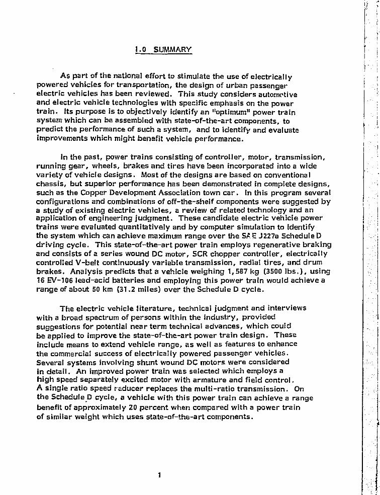
1.0 SUMMARY
As part of the national effort to stimulate the use of electricallypowered vehicles for transportation, the design of urban passengerelectric vehicles has been reviewed. This study considers automotiveand electric vehicle technologies with specific emphasis on the powertrain. Its purpose is to objectively identify an "optimum" power trainsystem which can be assembled with state-of-the-art components, topredict the performance of such a system, and to identify and evaluateimprovements which might benefit vehicle performance.
In the past, power trains consisting of controller, motor, transmission,running gear, wheels, brakes and tires have been incorporated into a widevariety of vehicle designs. Most of the designs are based on conventionalchassis, but superior performance has been demonstrated in complete designs,such as the Copper Development Association town car. In this program severalconfigurations and combinations of off-the-shelf components were suggested bya study of existing electric vehicles, a review of related technology and anapplication of engineering judgment. These candidate electric vehicle powertrains were evaluated quantitatively and by computer simulation to identifythe system which can achieve maximum range over the SA i_ J227a Schedule Ddriving cycle. This state-of-the-art power train employs regenerative brakingand consists of a series wound DC motor, SCR chopper controller, electricallycontrolled V-belt continuously variable transmission, radial tires, and drumbrakes. Analysis predicts that a vehicle weighing 1,587 kg (3500 lbs.), using16 E11-106 lead-acid batteries and employing this power train would achieve arange of about 50 km (31.2 miles) over the Schedule D cycle.
The electric vehicle literature, technical judgment and interviewswith a broad spectrum of persons within the industry, providedsuggestions for potential near term technical advances, which couldbe applied to improve the state-of-the-art power train design. Theseinclude means to extend vehicle range, as well as features to enhancethe commercial success of electrically powered passenger vehicles.Several systems involving shunt wound DC motors were consideredin detail. An improved power train was selected which employs ahigh speed separately excited motor with armature and field control.A single ratio speed reducer replaces the multi-ratio transmission. Onthe Schedule D cycle, a vehicle with this power train can achieve a rangebenefit of approximately 20 percent when compared with a power trainof similar weight which uses state-of-the-art components.
1
R vi
i
2.0 INTRODUCTION
By the turn of the century, automobiles powered by the Internalcombustion engine (ICE) and battery powered electrics were competingto replace the horse in urban centers.. At their peak acceptance, around1912, It has been estimated that several hundred thousand electric vehicleswere in Use throughout the world (Ref.1) .
The features of the present gasoline powered ICE vehiclehave developed over a long period of -efinement. These Include:
• Favorable initial cost,
• Good performance,
s Inexpensive fuel, and
• Long range.
England has continued to build and favor electrically powered vans(milk floats), but the electric vehicle has virtually disappeared from theAmerican market. In the U.S.A., a small group of Independent experimentershave continued to build electrically powered road vehicles, and several com-mercial ventures to build and m.7--ket electric road vehicles, such as Sebring-Vanguard, were established throughout the years. Battery powered propulsionhas been well suited to various off-the-highway vehicles such as industrial forklift trucks, golf carts and underground mining machinery, Lower maintenancecosts and longevity are well documented benefits of the electrics, but their higherinitial cost and lower overall performance have been drawbacks.
Within the current decade, we have been faced with both an energy °1crisis and an environmental crisis. It has been recognized that theearth's fossil fuel reserves are finite and we must take increasing f
t
advantage of other energy sources. These Include, for example,hydroelectric, nuclear, wind and solar power. Moreover, the recentoil embargo has stimulated the se of domestically produced coal andthe establishment of minimum fut economy standards for vehicles.
A significant portion of air pollution results directly from theuse of gasoline powered vehicles. This problem Is particularly severeIn urban areas. As a result, a significant effort is being made to reduceexhaust emissions. The use of electric vehicles allows the energy 1conversion process to take place at a central power plant where
2
pollution is easier to control. it also offers the opportunity to makea major shift in the transportation sector energy-base from foreignpetroleum to other sources.
Due to the low energy density of currently available batteries, elec-trically powered vehicles are not presently capable of both the accelerationperformance and range of ICE vehicles. There is significant federalsupport for battery technology programs and for hybrid systerns whichcombine the range benefit of the internal combustion engine with thepollution-free operation of electric power. However, it is possibleto fulfill a portion of the transportation needs with state-of-the-art electric ivehicles. Studies have shown that an electric vehicle with a range of129-161 km (80-100 miles) would meet the second-car requirements of asignificant portion of the population (Ref. 2) If a minimal level of performancewere acceptable. Programs to Improve batteries, vehicle designs andpropulsion system components are underway.
There is a rather voluminous literature on electric vehicles (seethe Bibliography) and much of this information was reviewed in the courseof the present study. Vehicles have been built in a wide range of con-figurations. Some use existing ICE chassis and others are designed from the"ground up". The criteria for selecting power train systems and componentshas not, however, been clearly established. Judgment indicates thatcomponent efficiency Is significant. Since most devices have efficiencieswhich vary with load, speed rnd environment, no particular set of componentsclearly offers optimum per-forrrance for all driving conditions.
This study considers automotive and electric vehicle technologieswith specific emphasis on the power train. Its purpose is to objectivelyidentify an "optimum" power train system which can be assembled withstate-of-the-art components, to predict the performance of such a vehicle,and to Identify and evaluate improvements which might benefit vehicleperformance.
An electric vehicle power train begins at the battery terminals andends at the road. Battery technology and overall vehicle design arebeyond the scope of the present study. Typically, an electric vehiclepower train consists of a controller, a motor, running gear, fL<<,r wheels andtires, and four brakes. As defined in the contract statement of work, state-of-the-art components are those that are available off-the-shelf as standardItems or can be manufactured by special order Involving limited designmodifications such as special mountings. Components that require develop-mental engineering are not considered to be state-of-the-art.
i
is
3
The urban passenger vehicle is the focus of this Investigation.The statement of work defined basic vehicle characteristics, such asweight, aerodynamic drag and battery parameters and specified thatthe vehicle must perform over the SAE J217a Schedule D* cycle, at aconstant 72 km/h (SS mphl and also climb a 10 percent grade at 49 kWh(80 mph) . A design objective was to maximize range over the SAE'S cyclewith a power train capable of meeting the speed and grade requirements.
This program does not specifically address the Issue of costeffective design for a state-of-the-art power train. It has been assumedthat the commercial availability of components Implies reasonable cost.Actual cost will depend upon market demand and appropriate manufac-turing techniques.
Information was obtained by literature search, by In-person andtelephcne interviews and by mailings to manufacturers of vehicles andcomponents. A number of vehicles were examined at NASA-LERC andat the Electric Vehicle Exposition In Chicago In the spring of 1977. Fromthis data base and by applying engineering judgment, various powertrain design approaches were identified and studied. Computer-aidedanalysis was one tool employed to select the state-of-the-art power trainand to evaluate range increases achievable with various improvements.
The review and assessment of state-of-the-art electric vehiclesand power train components is presented in Chapter 3.0. A preliminarydesign of a power train based on these components is developed InChapter 4.0 and Improvements are evaluated in the last chapter.
Throughout this report, reference to "the SAE cycle" implies theSAE J727a Schedule D driving cycle.
4
^y4
ul
F
Y
^I
iF>r 3.0 ASSESSMENT OF THE STATE-OF-THE-ART IN1 E
ELECTRIC VEHICLE POWER TRAIN TEC',ANOLOGV
y( The conversion of electrical power into mechanical motion is basicto our industrialized society. Machinery, powered by electricity, finds
' significant application in most industries. Within the transpo rtationfield the most common types of electrically powered vehicles are:
^ ® Golf carts
• Railroad locomotives and subway cars
.'; s Industrial forklift trucks
e Delivery vans ( "milk 'floats" in England)11 ^
• Mine vehicles
• Motorized wheels for earth moving equipment
a Highway passenger- vehicles.
For each type of vehicle, mission goals, environmental constraints andeconomic considerations establish requirements which result in specificconfigurations and component selections. Vehicles and machinery usedin underground coal mines are electrically powered because of boththe fire hazard associated with internal combustion engines and the airpollution (ventilation) requirements. Dynamic (or regenerative)braking is employed in large earth moving equipment primarily tominimize the servicing of conventional brakes rather than to conserveenergy. Contactor controllers are cost effective for delivery vansbut the smoothness of control desired for passenger vehicles generallyleads to the pulse (i.e., chopper) type of motor controllers.
Many electric passenger vehicles have employed the same DCseries wound motors and SCR controllers originally developed for theforklift truck industry. However, due to the difference in mission, thisapproach can lead to a less than optimum propulsion system design.
I
r3
i
4
5
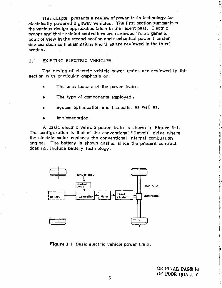
This chapter presents a review of power train technology forelectrically powered highway vehicles. The first section summarizesthe various design approaches taken in the recent past. Electricmotors and their related controllers are reviewed from a genericpoint of view in the second section and mechanical power transferdevices such as transmissions and tires are reviewed in the thirdsection.
3.1 EXISTING ELECTRIC VEHICLES
The design of electric vehicle power trains are reviewed in thissection with particular emphasis on:
a The architecture of the power train .
IQ The type of components employed
o System optimization and tradeoffs, as well as,
rr Implementation.
A basic electric vehicle power train is shown in f= igure 3-1.The configuration is that of the conventional "Detroit" drive wherethe electric motor replaces the conventional internal combustionengine. The battery is shown dashed since the present contractdoes not include battery technology,
iDriver Input
ControlLonlc ^ Rear Axle
r----1 TrflnsBattery Cnntrnlicr Atatnr Rilssltm DifferangalL __j
Figure 3--1 Basic electric vehicle power- train.
1
1
1.
i
I
e
}
6
^Ii Many electric vohicle tdosigns zrttempted to match the performanceof convention:tt Int€rrnul combustim vehicloi., `i`he CM Eleotrovair(Ref, 3) and the Ford Cortina FsttttaWrr oYl i al, ) tit•e xamptes, TheHead for Improved 41ttorles was apparent .end some of these vehlelesusad high to iparatura prototype battarles,
Analytic studies indicate that lighter vehicles with higlier batterymztss fmactlons (r•;rtio of b.-ttery walght to totel weight) should httvesupurlor perform ice. Sc^veml studies (I.e., lief, 5) have attemptedto Compare electric vehir~le performance by normi l axing perfomtr+ne-edot; Wth respect try battery mass frAction or overall m',ight. Unforatumtely! the nurrtiber of well documented vehicles Is small and test con"ditlons vary, Thorefore, a statistical apprvr3ch to assessing the state-ofthe-art for power traln featuros would not appear to be trultful. However,the Commonality of several feats..rr •es rind the trends In recent power traindesigns can be observed In the data
x,111 Electric Vehicles Designed by The l^rrthc^s{crst
A signiflezint population Of independent &%ctric ve111ele e±;porImenttit'shave for several years, been building, testing and using electric 111911wayvehicles. There are several regionial clubs which serve the membersby providing a means to share ez\perlenm Suet) or•gcnlxatlons Includethe Electric Vehicle Associntion of Ohlo, which claims to have ovell00 active m©mbers. Not unlike the 1 °hot-rodder" who Wdlfles a vehiclefor° cgreator performance, their approach has been to convert existingcompact cars, such as VW, Renault and Austin, to electric power.Table 3°1 lists the basic characterlsties of several such designs(Ref. 6) . Objective test data Is generally not avallable.
The selection of components fc)r these velilehes this necessarily beendictated by aconamlcs anal nvahlabhlity, The fundamental objectiveIms been to packago the hardware :Ind "make the system work". It isnot uncommon to see used forklift truck or goat :art motors and aircraftrgonerators Ire tlieso vehicles. Encginearing tradeoffs in the deign are quiterare. The technology employed in the golf cart and forklift truck industryfinds application In these designs because these Industries are virtuallythe only sources for relatively Inexponsive components,
t -
F
: i
^ F
f
4
7 j
r ^:
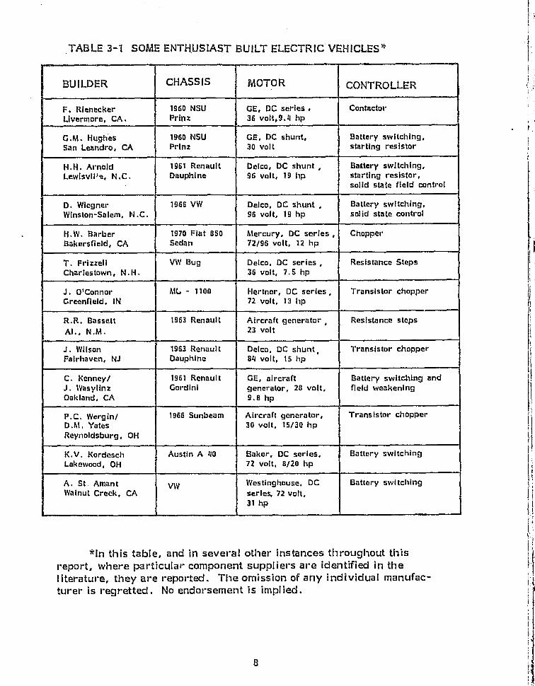
TABLE 3-1 SOME ENTHUSIAST BUILT ELECTRIC VEHICLES*
BUILDER CHASSIS MOTOR CONTROLLER
F. Rienecker 1960 NSU GE, DC series . ContactorLivermore, CA, Prins 34 volt;9.4 hp
G.M. Hughas 1960 NSIJ GE, DC shunt, Battery switching,San Leandro, CA Prinz 30 volt starting resistor
N.W. Arnold 196I Renault Delco, DC shunt , Battery switching,Lewlsvll le, N.C. Dauphine 96 volt, 19 hp starting resistor,
solid state field control
D. Wlegner 1966 VW Delco, DC shunt , Battery switching,Winston -Salem, N.G. 96 volt, 19 hp solid state control
H.W. Barber 1970 Fiat 850 Mercury, DC series , ChopperBakersfield, CA Sedan 72/96 volt, 12 hp
T. Frizzell VW Bug Delco, DC series , Resistance StepsCharlestown, N.H. 36 volt, 7.5 hp
J. O'Connor ML - 1100 Hertner, DC series, Transistor chopperGreenfield. IN 72 volt, 13 hp
R.R. Bassett 1963 Renault Aircraft generator , Resistance stepsAl., N.M. 23 volt
J. Wilson 1963 Renault Delco, DC shunt , Transistor chopperFairhaven, NJ Dauphine 84 volt, l5 hp
C. Kenney / 1961 Renault GE;, aircraft Battery switching andJ. Wasylinz Gordini generator, 28 volt, field weakeningOakland, CA 9.8 hp
P.C. Wergin / 1966 Sunbeam Aircraft generator, 'Transistor chopperD.M. Yates 30 volt, 15/30 hpReynoldsburg, OH
K.V. Kordeseh Austin A 40 Baker, DC series, Battery switchingLakewood, OH 72 volt, 8120 hp
A. St. Amant VW Westinghouse, DG Battery switchingWalnut Creek, CA series, 72 volt,
31 hp
fln this table, and in several other- instances throughout thisreport, where particular- component suppliers are identified in theliterature, they are reported. The omission of any individual manufac-turer is regretted. No endorsement is implied.
8
jI
1 t
{
On
9
A major virtue of these conversions Is practicality, Vehicles whichare built using existing automotive and Industrial componentseasily fit into the etc€ -t€ng infrastructure. Repairs acrd serviceare obtainable, or within Una reach of the "do-It-yourselferr', and thehardware Is well dev-.loped, safe and rugged.
Interest has been large enough to encourage the formation of severalcommerical ventures to produce and market electric vehicles. Firms such asElectric Vehicle Associates, Inc, (EVA) have their roots In -the enthusiast sector.
3.1.2 ]Domestic Commercial Electric Vehicle Conversions
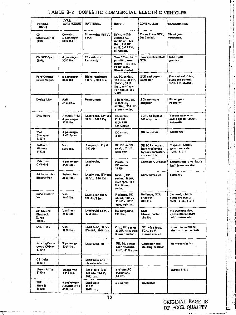
A summary of the characteristics of several domestic, commerciallyproduced electric vehicle conversions Is presented In Table 3-2, Datawas not avallabe for all parameters.
Most domestic and foreign electric vehicle programs have includedthe conversion of a conventional vehicle as a first generation test bed.Expediency and overall project emphasis are the rationale for this choice.In several cases the primary focus of the project seems to be the demon-stration of an advanced battery concept. For example, the GM Eiectrovair 11employed experimental sliver-zinc batteries and an AC motor drive was designedto match the acceleration and speed performance of its Internal combustion enginecounterpart. The major portion of the engineering design effort was centeredaround the AC motor contraller.
EVA and Waterman designs are conversions of compact conventional vehicles.Both retain the original transmission, and, In the case of the Waterman DAF-baseddesign, this Is a V-belt continuously variable ratia system. Sattronic, and AMGeneral have concentrated on the commercial market by using the conversionapprcmch. The Eattronic motor and controller are typical industrial designswhereas the AM General .seep employs a compound wound motor and two phaseOC chopper.
3.1.3 Domestic Electric Vehicles Designed From the Ground Up
It Is generally recognized that the Ideal electric vehicle shouldbe designed from the ground up. In this manner, the limited energystorage capacity of elactrochemical batteries can be used most efficientlyfor vehicle range and performance. Analytical studies have shown the
k^
}
l r.
1t ^ ,
rt
# J
a
}
{
I#
F+5
{ l Ir
'
1
k
1f
R
t
--• 1 L L
hl P
TABLE 3-2 DOMESTIC COMMERCIAL ELECTRIC VEHICLES iTYPE/
VEHICLE CURS WEIGHT BATTERIES MOTOR CA !TROLLER TPANSMISSION(Dale)
GM Ccrvalr, Sliver-zinc 330 V. Delta, 4*1a. Three Phase SCR, F)xod gearElwarovair 11 S pasaenger 6OAh 3 phase AC O11 Coolad. tsduction.(1967) 3400 tbs. Indtxtlon, 130
tbs., 115 HPat 13,W ftpm,all tznled.
GM }CEP Opel 4 passanper 21r.t:-air and Two DC Buries In Two syrxhronlaad Bail Input(1170) 30001bs. Lsad-acld p2rallel, tear SCR, peerbox.
amount. 1211' Ibs.,21 HP Mach.Blower coaled.
Ford Cortina S paasertpar Nickel -cadmium GE DC series, SCR and bypass Front wheal drive,Estate Wagon 3036 tbs. 110 V., 9D0 tbs. 150 tbs., 4a HP, contactor standard manual,
too V., 26 R. 2.11.1 in second.lb;., 1110o rpm.Fan cooled (60watt)
Doeinp L .RV Rail Puntograph 2 In series, DC SCR armature Fixed gear62.0001b7. separately chopper reduction
exalted, 210 HP.Slower coaled.
EVA Metro flonault R - 12 Lead-acid, EV-106 DC zertas SCPL, 3to bypass, Tarque converter4 passenger 96 V., INN tbs. 13 .4 HP 340 amp limit. and 3 speed Renault3150 Ibs, 4500 RPM automatic.
Fan Cooled
EVA 4 passenger DC shunt H ai =Pnt=tor AutomaticContactor AMC Neer BHP(1977)
SattronIc Van Lad-geld 112 V GE DC serles OE SCR chopper, 2 speed. helicalMinivan 15800 1121, 33D Ah. 1}4 V., £2 HP. field weakening pear rear axle(1973) 8000 rpm. bypass contactor, 1.96, 1.0.1
current limit.
Waterman 4 passenger Land-said, prastallte, Contactor, ) -spawl Continuously variableCHW-116 2100 tbs. 48V DC serles trait transmission
12 HP
Jet Industries Subaru Van Laud-acid, EV-106 Baldor, DC Cableform SCR StandardElectra-Van 2500 lbs. 46 V., 910 tbs. serles. 10 HP.
3500 rpm, 161tbs. blowerC401 ad,
Dana Electric: Van Lead-acld 144 V. Rallana. DC Reliance. SCR 3-spend, clutchVan 1000 tbs. 320 AhIS hr. shunt. 120 V. ciwpper, standard manual
33 HP at 425D No tbs, 3.03. 1.75. 1.0 1rpm, 130 tbs,
AM General Van/Jeep Lead-said S4 V.. In compoasd, SCR No transmission,Electruck 3640 Ibs. 1250 tbs. 2131b&. blower coaled conventional shahDJ-5E 710 tbs, with universals
(1975)
Otis P-300 Van Load-acid. 96 V, Oils, DC series GE put" type. None, conventional31(i0 ibs. 6V-106, 104C tbs, 3D HP, 4000 rpm SCR. 96 V shaft with universals
Blower tooled. blower cooled
5ebr.InplVan- 2 passenger Lead-acid, 40 GE, OC series Con tacLorand No transmissionptmrd Citicar 130D Ibs. rear mounted, stertln8 razwor(1974) 6 HP. 4100 rpm.
GE Delta Lad-acid and .11971) nick al -eaaiml um
Ut*er Alpha Doelge Van L.aed-acld (241 3-phase AC Olrect 1 .6 .1(1974) Soso Ibs. 220 Ah. 144 V, Induction.
1433 tbs. 34 HP.
EFP 4 passenger Land-sold DC earle a Contnctvrattars 11 Renault R-11'1 120 V111s41 4700 Ibs. 190 tbs,
yaORIGINAL PAGE L5OF POOR QUALITY
WIPPEKEKTIAL TIRZS BRAKES MFOPAIANCE ®tEFt RENCE
Slandard U mph a+px; f-60/17 (3)NK. 410 - 70 mi. ean@a
Standard 60 mph max 9-30110 (0)
3.11 1 04tc. 7, a0 mi, t
3.l.1 Radial 77 mph max. (3rd (4)gear}, a0 mi. at2S mph
Dynamie (re- (4)nerative
tienai) andydraulit disc.
1.34 1 Radial 40 mph max., 56 mi.(t0}, (11), (12)153 R-13 at IS mph. 27 mi. alurin
32 psi urban cycle
{l3)
Hypoid 6.70 x 1S Hydraulic 60 mph max., i0 mi. (14)3.07; 1 at 10 mph.
Rapenerative 45 mph max (15)available 60 mt. at 30 mph
Standard grldpaltax Hydraulic 4S mph RAX- (10}iKilil, bias ply 40 mi. at 40 mph#0 psi.
Darns Raptnerative SO mph max.. (1617,17:1 and hydraulic 200 mi. at IS mph
1.19 1 CR 75-15 Rep"rative 45 ml_ at 30 Mb. (17), (101(^ G) over IS mph 0-70124 sat., 30 mi,
and hydraulic an cycledrum
Standard Uniroyal Rally Hydraulic 0-30/1I sac„ (18), (IO}5.17.1 180, a ply at W. an cycle
radial, ITS-SK13. 31. pal.
6.f3:1 Cw+odytaar. 13 Kldrum 351nph Msex. (14}, (I0)2 ply nylon hydraulic 36 ml. at 2% nrph:+1.50x43. - 20 1nt. ao cycle
i So pal.
180 tnl at 20 a+ph (21)00 ml at 46 wph
g4nd.rd R►g"rallve (22)stxi hydrllutIt
I- R04wativa. 723 ml. at 30 1®ph (23)tadla
Whset 22 ail. an cycleaieec.
yl ^
it
r
6R21GINAL PAGE
QUALITY
}. TABLE 3-2 DOMESTIC COMMERCIAL ELEC TRI C VEHICLES (Continued)a
11
1 y
E '
1
ri 1
,
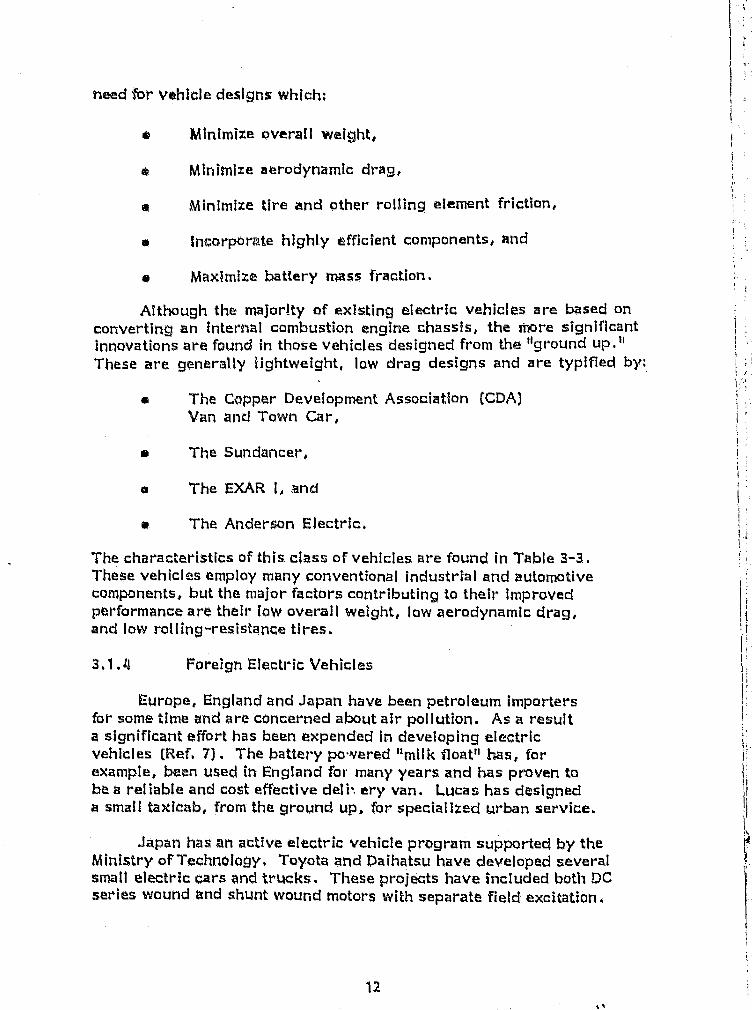
treed lbr vehicle designs which:
Minimize overall weight,
a Minimize aerodynamic drag,
0 Minimize tire and other rolling element friction,
s IncorporAte highly efficient components, and
0 Maximize battery mass fraction.
Although the majority of existing electric vehicles. are based onconverting an inter91al combustion engine chassis, the more significantinnovations are found in those vehicles designed from the "ground up."These are generally Ughtweight, low drag designs and are typified by;
a The Capper Development Association (CDA)Van and Torn Car,
Y The 5undancer,
ao The EXAR 1, and
ar The Anderson Electric.
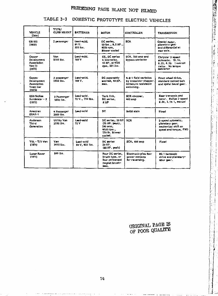
The characteristics of this class of vehicles are found in Table 3-3.These vehicles employ many conventional industrial and automotivecomponents, but the major factors contributing to their improvedperformance are their low overall weight, lour aerodynamic drag,and low rolling-resistance tires.
3.1.11 Foreign electric Vehicles
Europe, england and .Japan have been petroleum importersfor sometime and are concerned about air pollution. Asa resulta significant effort has been expended in developing electricvehicles (Ref. 7) . The battery powered "milk float" has, forexample, been used in England for many years and has proven tolie a reliable and cost effective deli% ery van. Lucas has designeda small taxicab, from the ground up, for specialized urban service.
.Japan has an active electric vehicle program supported by theMinistry of7echnaiogy. Toyota and Dzlhatsu have developed severalsmall electric cars and trucks. These projects have included both DCseries ground and shunt wound motors with separate field excitation.
12i .. -A
()RIGZNAL PAGE 15Off' pQOR QUALM
;- l
1.
Ir
Plre';XMING PAGE BLANK NOT ffli l) rr
TABLE 3--3 DOMESTIC PROTOTYPE ELECTRIC VEHICLES
TYPE/VEHICLE CURB WEIGHT BATTERIES MOTOR CONT.%DLLER TRANSMISSION
(Omit)
GM 312 t passenger Lewd-acid, DC aarlai, SCR Caaxlal motor,(1969) 94 V. So lbs., 11.5 HP., planetary gear
329 lbs. 40DO rpm, and differential atBlower cooled rear axle.
Capper Van Lead-acid, GE, DC aeries SCR. S00 amp and Chrysler 3-spatdDevelopment SfDD lbs. 103V S Interpotes. bypass contactor automstic _ 15.14,Association 12 HP. at 4725 9,33, 6,30: 1 overallVan III rpm, 231 lbs. ratios. No torque(1970) converter
Copper 2 passenger Lead-acid, DC separately 4.6:1 field variation Front wheel drlvt,Development x952 lbs. I09 V. excited, 40 HP, by transistor chopper, standard toothed beltAssoclation coax. Armature resistance and spiral bevel gear.'Town Car switching.(1976)
E5HlMeKee 2 Passenger Lead-acid. Tork link, SCR chopper, Rear transaxle andSundancer - 2 1600 lbs. 72 V., 750 Ibs. DC serles. 400 amp motor. McKee 2-speed(1972) 8 HP 6.09, 3.14: 1, manual
Amectran 4 passenger Load-acid DC Solid state FixedEXAR-1 2900 lbs.
Anderson Utility Van had-acid DC serlas, 20 HP SCR 2-speed automatic.Third 2500105. 72 V (35 HP. peak), planetary gear.Generation 240 amp, mechanical shift an
4000 rpm., spend and torque, FWD170 W. Blowercooled.
TSL-T13 Van Van Lead-acid DC serles SCR, 600 amp Fixed(1974) 3000 lbs. 34 V, 900 Ihs. 20 HP.
(35 HP. peak)
Lunar Raver 50D lbs. Four DC series, Electronic plus four 00:1 harmonic(1971) brush type, or power contacts drive and planatary-
four permanent far reversing. spur gear.magnet brush-(ess.
4-y.
t •i ',f -
t
,^ t
k
1 I
l ,^
}
f
14
Jj C
IF Y
Y rIII i I
lk
TABLE 3--3 DOMESTIC PROTOTYPE ELECTRIC VEHICLES (Continued)
A1FFA ENTiAL 'TIRES !•RAMS PERFOR"NCE MrIKEHCE
S-0:1 overall ratio. 45 hash tnax. (311}1l-30112 e4c.100 tat. at 34 r+ph.
Front twhwl drive. Firestone Hydraulic (34)Murat Hy-Vc chain radialto dlt(arantlal.
4.11s,1 AR 70-13 40 mph mtx.(40}+ (AIJ. (10}radial. 0 - x0;11.2 s.c.
Dona VO-20 Gdodtyeer l}tacldrum 100 mt. at 30 mph, (42(IOIM railing hydraulic 45 ml. at 60 mphrviatalancci.S1S x a. 30 psi.
11.11:1 Goodyear, Run Mac 1lrakas, w3 mph max. (43)Fiat. 100 m1. at 55 mph
Radial, Atsldrurn 5S tr .h max.. (44). (451USX 15. hydraulic 60 mi. At %S mph
7.12 . 1 Radial, Diseldrum 40 mph max, (0)163 x 15 0 .. 30116 sec.
30 ml. on cycle
32 In. diamattr 4 wheal rover 10 mph (47)wire mash. erative !wakes 74 ml. range
i
The trend to the separately excited © C Motor and regenerativebraking is apparent both in Japan and in Europe. Chopper typecontrollers are also quite common.
A summary of the characteristics of many foreign electricvehicles is presented In Table 3-4.
3.1.5 Summary and Design Trends
A major objective of efficient electric vehicle design is tominimize overall weight while maximizing the battery mass. Thepackaging of passengers, battery pack, motor and controls is atask requiring care and ingenuity. Generally the overall vehiclebeady design presents constraints on the power train configuration.For example, the front mounted motor/rear wheel drive is incompatiblewith the central "battery tunnel" frequently suggested for state-of-the-art electrics. Also, the modern "hatchback" design may precludethe use of a rear mounted motor/transaxle. Individual wheel mountedmotors are an interesting configuration which eliminates the differentialand may allow a simple form of redundancy. A review of the datapresented in Tables 3-1 through 3--4 as well as related studies andtechnical literature (see the Bibitography) suggests the followinglist of power train architecture:
ry
s4
,t
kry»
}
a Front mounted motor/rear wheel drive,i
Rear mounted motor/rear wheel drive,
Front mounted motor/front wheel drive,
Rear mounted dual output shaft motor, and
+a Individual wheel motors (Z or 4).' ^
rt
The concept of "load levelling" has received attention in theelectric vehicle literature because present lead-acid batteries are runable to efficiently deliver the surges of power needed for acceler-ation or to efficiently accept regenerated energy. Much of thiswork has been theoretical and har proposed the use of:
k
ia Flywheels, G .
a Liquid or gas accumulators, and
a Supplemental batteries.
16
4;,
1
0
e
i
L^ P
'r r
r
F
i
PRE, E-CFI) ,G v=' swa 1,40T
TABLE 3-4 FOREIGN ELECTRIC VEHICLES
TYPE/VEHICLE CURB VITIGHT BATTERIES MOTDR COMOLLER TifANSMISSIOh(Date)
Thev 11 4 passenger Lead-acid Tongyusn, qC SCA chopper Flx, d reductionTaiwan 1 2§54 lbs 132 V. aeries,r"rmount 1.;.1
! 1102 Ibs. 176 Iba., 34 HP.6000 rpm, knowercoow.
Lucas Taxi U51 tbs. Lsad -sold DC Series. front Lucas SCRs Double rsduction.I7l76) I16 V. mount transverse, =xnWar Morse Hy Vo chain,
CAV, S0 HP. transverse todifferential.
Daihatsu KogyD 4 passenger Lead-scld. Two roar whaet. Y,CR rJvm*mr Rear nAunted,Lightweight car ;DID lbs. 96 V, DC series, automatic, 2-speed(1972) 220 Ah/5 hr. 7 . S HP. each.
as V.
Toyota 5 passenger Lead -acid. DC separately SCR chopper, Rear transverse
Compact car 3054 [bs. 122 V. excited 27 HP. automatic field trsunt, automatic,11972) 1S3 . 5 Ah/S hr. (20 kw) rated weakening torsional damper,
S4 hp- 140 kw) no fluid coupling,man. B lower 2-scmad hydrauliccmiad. 9rnm electric pump
Taypts 2 passenger + Load-acid, DC separately SCR Fixed gar rodgmiopSmall Truck 770 tbs. load 26 V., excited 13 HP.
135 Ah/S hr., rated, 13 HP.7231bs. max.
Enfield ;DOD 2 passenger + DC series, 6 stop contractor. Optional119761 2 children 49 V. mawdalay, field weakening
2100 ibs. I HP., 171 lbs .Eiower eoohad.
Bedford Van Van 120 V DC series, 5 step contactorTorque convener, -12RG 6000 Ibs. So H p , (patented) Variable KineticEngland Driw. 4 . 6 at stall.
905 cruise efficiency
CometsFord 2 passenger + Laud-acid (4) CAV type TM 55, Thyristor pulse Rzar transverse mountEngland 2 children 12 V DC series (2). c ritroller, fixed gear reductionfilial 12001bs. 120 Ah / S hr. 24v.. 5 HP. Sevccn Mk VI,
794 lbs _ Blower cooled . bypass contactor.
VW Electric Van Lead-acid DC separately Electronic. pulse Fixed year, V14
Transporter FQD0 lbs. 144 V. excited, Bosch width field frequencyStandard transaxlaapprox. ISO Ah/5 hr. and Siemens, 21 modulation.
1696 Iba. HP. (42 peak),6700 rpm max.Separate fan.
Damiar Benz Van Lead-said DC Separately Electronic, 2 position Fixed gear reductionLE 306 6500 lbs. ISO V. excited. 42 HP variable pulse width
approx. ISO Ah/3 hr. (70 peak], and frequency1234 ills. 6000 rpm inex.
Elcar Model 4 p4z%wVcr Lead-acid VC strin g , OE. SCR chopper With Fixed reduction5000 1500 lbs. R V. 20D Ali. 3.S HP., Roar contactors and(1975) ie*Mt. resistor.
SRF 2 passenger von Wirtz hip 750 -V DC w"rately ly armatu
ii
r
f
f
I
)
Conihi-Truk 1100 kg. 144 V. •xellw-1, IS HP, field, e
weakening oofltinuousty variablere intro!, Front wheal drive,
Israel contlnuoi:^ at transmission, flyr+heei
i [
4500 rpm.. i...E.
E
li
a '
ORIGINAL PAGP VOF POOR QUAUTY
78
DIFFERENTIAL TMES SKAKES PERFORMANCE REFUMNCE
Standard 39 nt h auk - (14)di trantlat 9 - 37113 atc4. 1.1 200 lei. at 30 mph,
5.93. t Rsptnarallve 60 mph max 1251and Girllnp 200 ml. at 30 a0hservo hydraulicbrakes.
Ra9t4arstive 55 aph max (26) . (27)and hydrsullt. 0-20r3 sac
173 mi. at 33 a=sh
Special Rtgensrative $9 mph sisx ..and hydraulic 0-]0:23 sac (26). (2 71, [261
190 mi at 25 mph
Raptrwrativa 31mph:mx (27), (29)and hydraulic 26 ini . over urban
cycle
(29}3.55.1 Radial, 0-3012 aw.33 psi 40 mph max
0-3014 sac (30)47 mph mss31 mi. over cycle
Qverall ratio 4.0 1, 4.4 x 10 Hydraulic drumsi 40 mph max. (31)hallul pinion. all xhaeis 40 ml. at 25 mph
l-30; 12 sac.
Radial Repanarative (32), (33)and hydraullc-
Standard Raptntrative 37 mph mss (341, (3S)and hydraulic
Stall Radial Hydraulic ss mi at IS aph (36)sR -143x10 40 mi at 40 mph
li-30 14 sac.
43 mph max (37)
N
I
I.,w
r
r
e
lr
lFF'
f.
1
pad
If '
f
iiY
f'
C
h
I ^
1
r
[j
1
I ^
1
1I
1
1 I
'a
V
TABLE 3-4 FOREIGN ELECTRIC VEHICLES (Continued)
( )RIGVN' AL PACT' Ft)P )'Ot)R
^^1f 19
Jq
r
^,
Flywheel systems have yet to be reduced to practice in electricallypowered vehicles. No known passenger vehicle has demonstrated sucha system and at least one study (Ref. 51 indicates that a similar Improve-ment in range is obtainable solely with regenerative braking. However,the predicted benefits of flywheel energy storage are encouraging,
In order to ensure safety, the accumulator storage conceptrequires excessive structural weight to contain high pressure fluids.Additional energy and pumping hardware Is needed to transfer thestored fluid.
The approach of using a supplemental battery ( i.e„ Ni-Cad)has been demonstrated in the GE Delta vehicle (Ref, 21) . This designapproach allows for the implementation of improved batteries as theybecome available, 11111ore study of the impact of this concept on range overthe driving cycle is needed to determine Its effectiveness.
Although battery development is beyond the scope of the presentstudy, it was necessary to obtzin parameters and discharge characteristicsof lead-acid batteries for use in range computations. Discharge charac-teristics of lead-acid batteries in electric vehicle applications are not well !understood, No model of the EV-106 battery (which was specifiedin the contract) that can be absolutely accepted is available. Performancemodels under conditions of pulsed loading, typical of use with choppercontrollers, are needed.. Even under steady discharge, the available predictions f(Ref, 48, 45, and 50) are not in agreement. Jayne (Ref. 51) identifiesand describes test results indicating increased effective capacity usingpulsed discharge techniques as compared to steady state discharge of the sameaverage current. Current work at NASA- -LERC Is aimed at investigating this I fapparent anomaly. ► r
Analysis indicates that no single power train can simultaneouslymaximize range at various constant speeds and range over various stopand go driving cycles. In addition, a system that maximizes range for yone set of conditions may be totally- unsatisfactory for another cycle. Forexample, where a design is optimized for maximum range at constantcruising speed and the vehicle is subjected to stop and go cyc„ng or grade lclimbing, the motor may ► overheat. A less extreme example is a vehicledesigned for efficient high speed c ruise which may have poor accelerationand tgradeability.
1
iThe vehicle chracteristics presented in Table 3-1 through 3-4
show significant variation in configurations, :rotor types, controllertypes, transmissions and tires. There does not, however, appearto be any correlation between these variations and the performancedata, This Is due to the more significant manner in which battery
20
ii
S
^ 6
rH
i
fti
characteristics and total vehicle weight affect performance.Detailed dynamometer testing of power trains has generally beenbypassed and vehicle performance has been reported for various,and sometimes arbitrary, driving cycles. The recently establishedSAE J227 test procedure promotes uniform testing. Unfortunately,much of the information published concerning particular vehicles ispromotional in nature. Moreover, many firms consider their designapproach and detailed performance data to be proprietary. Objectiveverification of the many performance claims is needed.
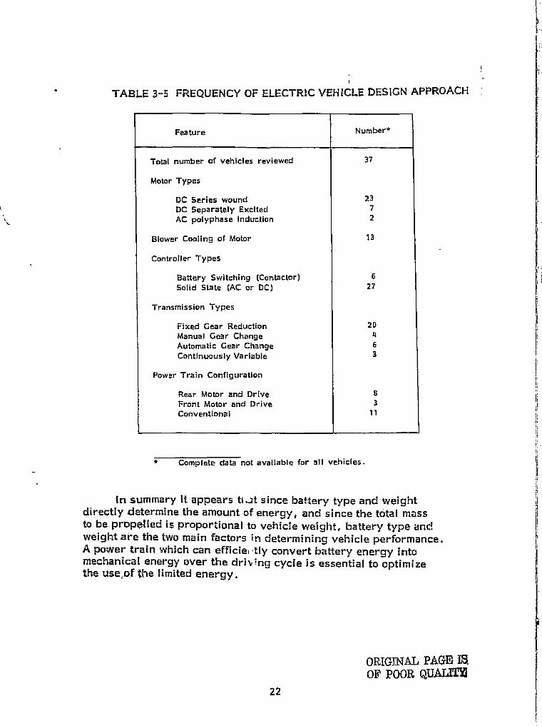
The frequency of occurrence of power train design approachesfor those vehicles reviewed in Tables 3-1 through 3-4 was obtainedand is summarizes! In 'fable 3-5. With this information, and theliterature reviewed, notable trends and common practice include:
! The most common motor type is the DC serieswound motor with an SCR controller. Significantinterest has been found in the separately excited,shunt wound motor.
0 Flower cooling of motors Is common.
r Most transmissions are fixed speed reducers.
0 The use of low rolling resistance tires, rollertype bearings and efficient ( i .e. , not hypoid)gearing Is desired.
2 A single motor transversely mounted near the drivenwheels (front or rear) appears most consistent withthe overall vehicle package design.
O An objective systems tradeoff study is required tooptimize power train design for a particularmission.
it;^ a
f
i'l
;i
r
21
- - --
TABLE 3--5 FREQUENCY OF ELECTRIC VEHICLE DESIGN APPROACHw
-1}
Feature Number*
Total number of vehicles reviewed 37
Motor Types
DC Series wound 23DC Separately Exciter[ 7AC polyphase induction 2
Blower Cooling of Motor 13
Controller Types
Battery Switching (Contactor) 6Solid State (AC or DC) 27
Transmission Types
Fixed Gear Reduction 20Manual Gear Change 4Automatic Gear Change 6Continuously Variable 3
Power Train Configuration
Rear Motor and Drive BFront Motor and Drive 3Conventional > >
* Complete data not available for all vehicles.
I
II
jl
ii
lIn summary it appears ti-A since battery type and weight
directly determine the amount of energy, and since the total massto be propelled is proportional to vehicle weight, battery type andweight are the two main factors in determining vehicle performance.A power train which can efficie, -tly convert battery energy intomechanical energy over the driving cycle is essential to - tirlizethe use,of the limited energy.
PI
ORIGINAL PAGE ISOF POOR QUALM
F
r
t
j
22i
3.2 MOTOR AND CONTROLLERS
The subject of electric motors for vehicle traction applicationshas a long and varied history. The first electric drive system togain prominence vms the Ward-Leonard system patented in the early1690's. Since then, complex electronic controls have been developedutilizing sophisticated solid state technology and motor control tech-niques.
3.7.1 Alternating Current (AC) Motors
AC Motors are extensively used In constant speed applications.The most popular type of integral horsepower alternating currentmotor Is the polyphase induction motor. Induction motors may beeither squirrel cage or wound rotor types.
Compared to a direct current machine of comparable performance,a "squirrel cage" induction machine has the following advantages:
a Lower- cost,
® Greater ruggedness,
a Brushiess,
0 Lower weight, and
• Lower maintenance.
Features of the wound--rotor motor include:
m Use of slip rings in the rotor circuit to providea means of varying the effective rotor resistance.
s
Rotor control circuitry isolated from the highpower stator supply.
Figure 3-2 illustrates the torque-speed characteristics of a typicalInduction motor at constant voltage and frequency. Two values of rotor-resistance are Illustrated. Induction motors with high resistance rotorsare less efficient than motors with low resistance rotors.
23
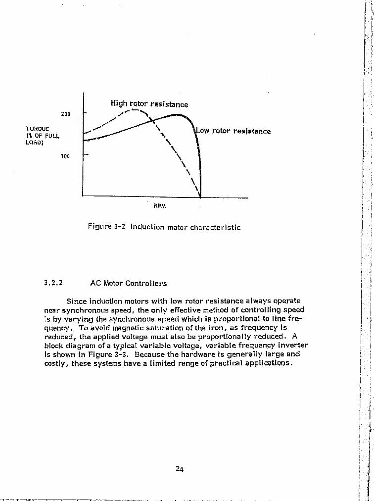
High rotor resistance
f°'TORgUEM OF FULL,LOAD)
to o0 ^
rotor resistance
RPM
Figure 3-2 Induction motor characteristic
3.x.2 AG Motor Controllers
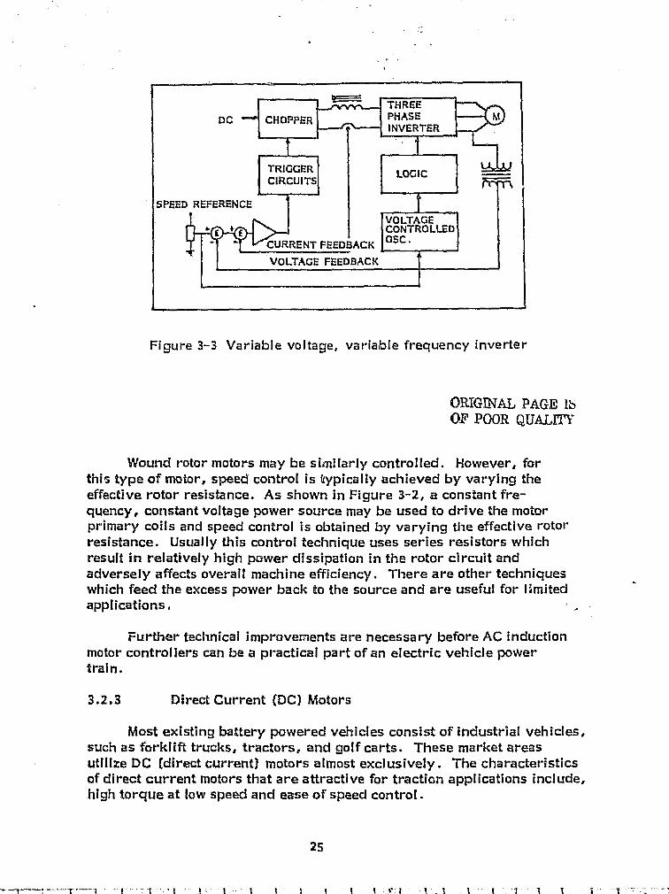
Since induction motors with low rotor resistance always operatenear synchronous speed, the only effective method of controlling speed's by varying the synchronous speed which is proportional to lime fre-quency. To avoid magnetic saturation of the iron, as frequency isreduced, the applied voltage must also be proportionally reduced. Ablock diagram of a typical variable voltage, variable frequency inverterIs shown in Figure 3-3. Because the hardware is generally large andcostly, these systems have a limited range of practical applications.
l O
4 THREEDC CHOPPER
rill
PHASE MINVERTER
TRIGGER LOGICCIRCUITS
SPEED REFERENCE
VOLTAGE+ E CflN t ROLLED
' CURRENT FEEDBACK 05C.
VOLTAGE FEEDBACK
Figure 3-3 Variable voltage, variable frequency inverter
ORIGINAL PAGE 16OF POOR QUALM`
Wound rotor motors may be similarly controlled. However, forthis type of motor, speed control is typically achieved by varying theeffective rotor resistance. As shown in Figure 3- -2, a constant fre-quency, constant voltage power source may be used to drive the motorprimary coils and speed control is obtained by varying the effective rotorresistance. Usually this control technique uses series resistors whichresult in relatively high power dissipation in the rotor circuit andadversely affects overall machine efficiency. There are other techniqueswhich feed the excess power back to the source and are useful for limitedapplications, I .
Further technical improvements are necessary before AC inductionmotor controllers can be a practical part of an electric vehicle powertrain.
3.2.3 Direct Current (DC) Motors
Most existing battery powered vehicles consist of industrial vehicles,such as forklift trucks, tractors, and golf carts. These market areasutilize DC (direct current) motors almost exclusively. The characteristicsof direct current motors that are attractive for traction applications Include,high torque at low speed and ease of speed control.
25
w^_
wawC6-c v.a
In addition, several motors are availatale off-the-shelf in the performancerange required for on-the-road electric vehicles. Suppliers include:
e Baldor 0 Prestolite
a General Electric a Reliance
a Gould a Westinghouse
e Lawnel a Century
In general, direct current machines are classified by the method ofenergizing the field. The most common types are:
a Series,
a Shunt, and
a Permanent magnet.
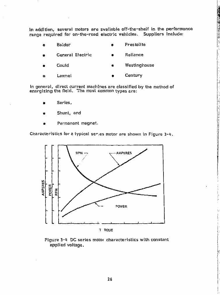
Characteristics for a typical ser'.es motor are shown in Figure 3 -4.
7 RQUE
Figure 3-4 DC series motor characteristics with constantapplied voltage.
26
^. _ _._..^ .--^ • ..^._.z r..z
Situnt wound motors are typicnily ust. d where) speed "ntrbl isdesired. Tills type of inotor remilly lends Itself to contr•ollK,1 brakingand regmar•ative applicatlans since thn pow pilt" In tlra Hold clrcult ismuch lower than the powu in th© w ,maturo uircult.
Permanant magnet motors aro iniZerently more officient duce tothe fact t1int no a\torturl flald supply Is required. Speed is direct4lproportional to arniatura voltt3ge and tho speed-torquer curvo and thecvtr •rr3nt tarqttrr etrr •va aro c trlto linear, pormanotzt trlrctnet motors 11,110tvallable In fraetional horsopowor and vvwy tote Intogral horsopowersixes only.
Direct current machines using wound fields ht^ve Boon genorally^nstrttetod for speelfilc cai^flciuratic^ns. Sol°los filc^ttt rrlc^i •or's aro ^^enotail^^applied in torelue demand situations wlwro preclso .peed contivi Is notretluh•ed. Shunt wound motors aro ^jenr vafly utill.-iM with Constant lard.varlablo speed applicatlons whetro preelse, speed control Is required.Both configuratlrans have loon uttii--cd In etiperltm^tlt:^i electric i^as^sorihortypo vehletes With varlod succoss
5.2.4 pc Motor Controllers
Spoed c untr-ol of dh , cLct ctrrront rnotore, Ina)3 Eio obtained by fieldcontrol, ar•niature voltago control. or a of Lvoth. Thes-0methods result In varying nuito r° speed:= torque t,t^:rracteri;:tic:: , Holdcontrol of a shunt motor can bo obtained with a small r1wostat In thecircult with little lass as the flold current Is low. Armaturc, voltgjecontrol can be performed In a similar manner. Armaturo currents,however, are high. up to 25 tImc}s grmiter than tho bold current, s«this method involvas bulky cwgvnents kited is loss offiiclent.
Battery Switching is a straight fci-w.,ird mvtlwy i of direct currentmotor control. using this mothod, the armotury voltage'. Is varied byStopping the motor cornrl?etions nemiss fl\end Inc.romonts of the con)[witobattery. Specific chartrcoteristics tit this tochniquo arc':
0 Controls requiry only contoctor . anO."tw c$iorR`lof* -
ft Without current limiting stele c.ht3n jos In vvdtagt•result In jovky oporatlon.
0 High starting currents arc, shared by severallaattet • ies In parapet.
Without care in baltanc Ing tho battory sysWm loading,unevo-n dlschat-ging and pren`:iture battory f€rllu1•0 mayresult •
2^we
—a4 RR

A typical four step controller Using six balanced battery sections isshown with a series motor In Figure 3-5. Operation may be improvedby adding a series resistor in the armature circuit. Unless theresistance Is removed from the circuit once speed Is attained, speedregulation will be poor due to the resultant voltage drop across theresistance as the motor is loaded. The series resistance must alsobe capable of very high power dissipation at reduced motor speeds.
FIELD
+ Figure 3-5 Six step controller. The contactors are energizedhin the following sequence: t & 2 (IV), 2 & 3 (2V), none{311), 1 & 3 (4V), 4 (,V), 3 (6V), V is the Individualbattery voltage.
Another method of direct current motor speed control Is obtainedby "chopping". A chopper control applies an effective variable voltageacross the motor through the use of the well known switching techniqueshown in Figure 3-6. The duty cycle may be proportioned by controllingthe "on" time pulse width, the pulse repetition rate, or both. Thismethod of control is extensively used in industrial vehicles such asforklift trucks. Characteristics of this type of control include:
r
Effective motor voltage is proportional to thebattery voltage times the switching duty cycle,
e rower transfer I: smooth,
;^1 0 Electronic packagt has established reliability,
o
Technique Is considerably more complexthan the battery switching technique, and
0
Control Is attained with low power components butactual power switching components are large andexpensive.
28
-F
Ll
Vall,genv
stia
Fbstd
ORRY'INAL PAGE ISoF, 1,00R Qtj-11^
I on I off I Tome
SM
Free Wheeling klatn CurrentSCR Conductlon ZDlade Conduction
Av*raga #iatar Gurront
L 'Average SCR Currant
A
! On I off T lene
Figure 3-6 Chopper Control Waveforms.
There are a number of manufacturers currently manufacturingchopper controls for series wound motors. They include:
10 Cableform a Reliance Electric
ti
mf General Electric a Sevcon
Sevcon and Cableform offer traction motor controllers with integralregeneration capability. Since most chopper type controls utilizethyristors or silicon controlled rectifiers (SCR) they are generaillyreferred to as SCR controllers.
The direct current motor control techniques described aboveare applicable to the electric vehicle and have been utilized with mostconfigurations of DC motors.
29
rR
^t
M-
3.2.5 Vehicle Control Requirements and Summary
An integrated traction control system for an electric vehicle isstill an unfilled need. Many have been developed utilizing sophisticatedlogic packages incorporating both analog and digital techniques to integratevehicle controls. A general purpose system is, however, not available.
Experimental vehicle designs vary extensively in the complexity of theelectronics utilized for the controller. The least complex is a simpletransistor gating .circuit utilizing discrete components. The most complexinvolves a 16 bit microcomputer providing complete real-time control ofall vehicle dynamic parameters. To date no complete specifications havebeen identified, nor total package developed, for an integrated tractioncontrol system. The requirements for a total electronic control systemneeds definition within such areas as:
m Accelerator -- If an objective is to duplicate conventionalvehicle behavior, the accelerator position should be atorque demand control input. However, it is possibleto provide other schemes such as speed control. Also,the electronic control of transmission gear ratios hasnot been significantly addressed.
Brakes - Definition of requirements for blending ofelectrical (dynamic or regenerative) brakes with frictionbrakes is needed. For example "coasting" could resultwhen releasing pressure from the accelerator or at anintermediate position so that the "feel !° of engine brakingis obtained.
a Operator Override - There are no specifications to requirea means for an operator to disconnect the vehicle in anemergency. This may be a desirable feature in a practicalelectric automobile.
® Battery Monitoring -- The existing criteria most commonlyused for determination of battery condition is batteryvoltage. A specification for state-of-charge as a function ofcharge depletion an.' charge replenishment due toregeneration should -je developed.
As a summary, Table 3-6 presents an overview of the motor/controller assessment for electric vehicle traction applications.
t
f
i
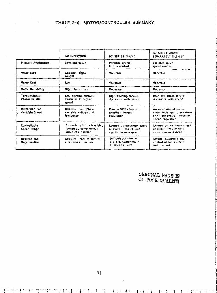
TASK ti 3-6 MC}'3 ORICONTROLLER SUMMARY
DC StILINT WDLINP,AC INDUCTION W SrRIES WOUND SEPARATELY EVITfn
Petmary Appticalion Ctrnsttnt sexed Variable sfir0 Vortatde steedtorque cfmntvaf speed control
Motor 5txe Comptial, light iltodcrate 8lwerawweight
Motor Cost Low M-werale Moderate
Motor Reliability High, brushtess Mrderait Moveraw
Torque'5peed Low starting torque, High starting tor que, thgh low spocd Ior,2ur,Characteristic maximum at higher dK(CaSeS with terra do:rrasts i%Qh speti+
speed
Controller Pot, Complhx, multiphase Proven SCR sheoper, An extension of serieslariablit Spvid varlable voltage and excellent lornuo motor IochnigUes, armature
fre.-luency regutatton and field control, ox.ttlentstwed re-gulation
Controllable As much as 8 1 is feasible Limited by maximum s peed Limilecd by maximum sPecdSpttd Mange Ilmited by synchrar,ous of motor , loss c f load of motor. toza i+ f ffetd
%Mod of the motor restitts in w arsprod remillf in oversr-"O
Reverse and Comolex, part of control Oifticull but state of Simple, sw+lcfti,rn andRNCnaraticv► elettromet function (lip arl. twit"•p ing In Control Pt low Curre»1
armalufr Cli-mW field Circuit
URI[tIIVAL PAGE 4OF POtell OUrLT,It.
31
3.3 MECHANICAL ELEMENTS OF AN ELECTRIC VEHICLE POWER TURIN
In addition to the orator and controller, an electric vehicle powertrain typically consists of.
0 A transmission to transform the high speed, low torquecharacterl- tics of the Motor to the low speed, high torqueroad load;
a A differential to allow power transfer as the vehicle negotiatescurves;
0 Bearings, drive shafts, universals and related mechanicalhardware,
o Tires and brakes.
The nature of these components in the conventional automobile is reasonablywell known. However, since little attention to fuel economy (efficiency) wasrequired as this hardware evolved, a review of the state-of-the-art was -undertaken to identify systems appropriate for the electric vehicle applica-tion.
3.3.1 Transmissions
A simple calculation illustrates the need for rotational speedreduction in an electric vehicle power train. For the case of 0.51 m(24 Inch) diameter tires on a vehicle travelling at 88 km/h (55 mph)the rotational speed of the tire is 770 RPM. Electric motors typically aredesigned to operate at several thousand (say 2) RPM. Thus an overall speedreduction in the order of 3: 1 is required. In addition, empirical motordata shows higher efficiency in the high speed, low torque region.
Transmissions can generally be classified according to:
Type of shift
None (fixed ratio reduction)Manual
- Automatic
4
r
i
}
32 F
1
i
T

a Ratio Incrementation
- DiscreteContinuous
0 Principle elements
Gear- Belt or Chain- Rolling traction- Hydrodynamic- Hydrostatic- Clutches- Combinations of the above
Table 3-7 lists several sources of transmission components and systemsIdentified during the present study. The list is not, by necessity, Allinclusive.
Fixed ratio reducers are numerous and are availabW in manypackaged forms as well as on a build-to-sult basis. They can beclassified somewhat by the type of gearing, belt or chain elementsused. For example,
Gear types include
Spur
HelicalWorm
Bevel
Belt types Include
- V-beltToothed (timing) beltsFlat belts
p Chain types Include
-- Standard roller type- Special
a^
,x

TABLE 3-7 MANUFACTURERS OF CANDIDATE TRANSMISSIONS
j
COMPANY TYPE
r`
j.
I k
American-Standard CVT - iluld driveDearborn, Michigan
Amer and Co. MIT - traction typeMannedorf, Switzerland
Emit Seeklege Multiratio planetary - auiomatic shiftWillow'ck, Oluo
Chrysler Corp Standard automotive tnanucl L automaueEast Syracuse, New York. N.Y. transmissions
Chrysler Marine Standard outonicitive insnuat L auM."tirMarysvilic. Michigan transmissions
Dana Corporation litanual shift, hydrostatic and fixed ratioAuburn. Indiana post type
Eaton Corp Fixed ratio pair reducersItlarshatt, Michigan
Excelermtlic Ctrl - tractian typrAustin, 'Texas
Fafnir Bearing; Cc CVT - traction typeNee. Brttmm. Connecticut
Floyd Drives Cc. CVT - tractior. typeDenver, Coiorad,
Fluid Di ive Enn-near,n£ Co Fluid torque converter L variable /poetKtlrncttt, Illinois "V" Felt
Ford Moto r Co. Standard autca rntive nunual L autcmaa_Livonia, Atichigmn transmissions
Gates Rubber Co. Belts for variable speed bell drivesDenver, Colorauc
Graham Transmrss.ons, Inc CVT - tracuon typeMenomonee Falls, 14mconsm
Mans Meynau Gmbh CVT - traction snd "V" belt typesGermany
Industrial Terlonics. Inc. CVT - traction typeAlin Arbor . Michigan
McKee Engineering Corp. Modiried STD automotive sutom ticPalatine, Illinois transmission
litarathon -LISA Inc. C1T hydtosutic typeStx^ `ord Connecticut
Morse Chain D+v Fixed ratio chain L W% types
Ithaca, Ilea York
i
Y
. T.,.
l .34
r
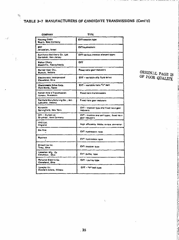
Nsureag Gmbli CV7 traction typeWueri. Was%Gal'many
SRF M hydrostaticJerusalem, Israel
Sumitomo llaehinery Co. Ltd. CVT-various traction elament typesCarlsmdt, fief+Jersey
Walter Chery CVTiSsadville, Pannsylvanis
Wormer Gear Div. Fixed ratio goer reducersflurtclr. Indisru
jDactronlatit: lncarporsted CVT - varlabls slip Iluid driveCleveland, Ohio
EhicArsiratic Drive Carp. V7 - variable ratio "'V" beltFort Worth, Texts
Holton Axle G Transmission Fixed ratio transmissionsJuneau. ifiiscontln
Falrfield Manufacturing Co., ktr, Fixed ratio pear raducsrsLafayette. indwrui
Winsmlth CVT - traction type and fixed ratio poorSpr ingfie l d. Haw York radvcars
SEY. - Eurodrive CVT - traction and self typos, fixed ratiop ruChsal. %&V Germany Dear ra iucers
AV$ Ltd.EnRIang Nigh efficiency Nobs sarque Converter
Ste RiteCVT hydrasLtic type
RpgreeaCVT hydrostatic type
Ernodrive Inc.Tray. Ohio CVT traction type
LeweNan Mfg Co-Columbus, Ohio CVT guilty type
Reliance Electric Co. CVT - pulley typeCleveland. Ohio
Lovejoy Ott. CVT - W" belt typeDowners Grovs, llliinols
i
t I s
dI
e
;k
TABLE 3-7 I&iANUFACTURERS OF CANDIDATE TRANSMISSIONS (Conttd)
COMPANY 'TYPE
35 a
•
The efficiency of gear reducers can vary widely but spur gear sets haveefficiencies that typically exceed 98%. Special gear systems offer high +
F reduction ratios in small compact packages. These include:
e Planetary ti ..
a Harmonic
e Planocentric
The planetary system is quite common in transmissions and is attractivedue to an inherently high power to weight ratio. i
V
Belt or chain type reducers are candidates for fixed ratio electric 3
transmissions as they, also, can be very efficient. A special chain type" produced by Borg Warner, the Morse HI-VO chain bears special attention. i
Power transmission efficiencies for this chain used in actual drives,within rated limits, are claimed to be as high as 99.5%. This chain .has been used as a drive train component in the CAA Van III (Ref. 39) 3 .
'i as wel I as the Lucas Taxi (Ref. 25) . Chains have been proven, by theirextensive use in motorcycles, as an effective vehicle drive train component.
j Multi ratio transmissions of the type currently used in conventionalautomobiles have distinct compatibility and availability advantages.As such they have found application in many of the conversions discussedpreviously. These transmissions include: ;F
Current automotive manual and automatic shifting { `transmissions, f
Standard and automatic transmissions used on other ivehicles such as motorcycles, small tractors and otherspecialty vehicles, and
r_
Several conversions have used standard manual transmissions morefor the readily available fixed- ratio reducer than for the multi-speed feature. In those cases, I.ttle effort was made to select multiple €gear ratios, but rather the transr ission was left in a single, "bestoverall", gear. In general consurier trends within the automotivemarket clearly discourage the use of a manually shifted transmission.The successful search for an efficient, automatic transmission will, ltherefore, enhance acceptance of the electric vehicle.
a Standard transaxie assemNies.
36
j#
1
Standard eautomoble automatic transmissions that have beenapplied to electric vehicles include:
61 The Chrysler 3-speed automatic (without torqueconverter) as applied to the CIA Van (Ref. 38) and
The Renault transaxie as applied to the EVA Metro sedan(Ref. 12) .
The use of thfAse transmissions In electric vehicles involves considerationof several factors,
The shift control heeds modification to 'properly interface withelectric controls,
r! A power drain n. ?5 - 2.2 kw (1 -3 hp) is typical due to theInternal hydraulic circuit, and
e^ Although the torque converter- is a source of inefficiencyIt serves to provide some degree of shock isolation withinthe power train,
Advanced Systems Ltd. of England has developed a transmission whichIs claimed to be as much as 25% more efficient than conventional units.It employs a Hobbs torque converter coupled to a Borg-1V;arner automatictransmission (Ref. 52 and 53) . This system has been demonstrated Into del Ivary van (Ref, 30) .
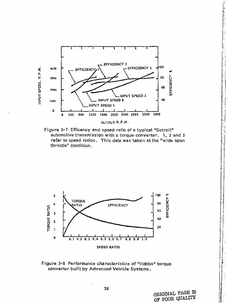
Figure 3-7 presents efficiency data for a typical "Detroit" automatictransmission with a torque converter. This data serves to illustratetypical transmission behavior, Efficiency data for the Hobbs torqueconverter Is given In Figure 3-8. in goner-tat. a torque converter Inseries with the transmission gives poor low speed efficiency and depressesthe overall off icioncy throughout the speed ranee.
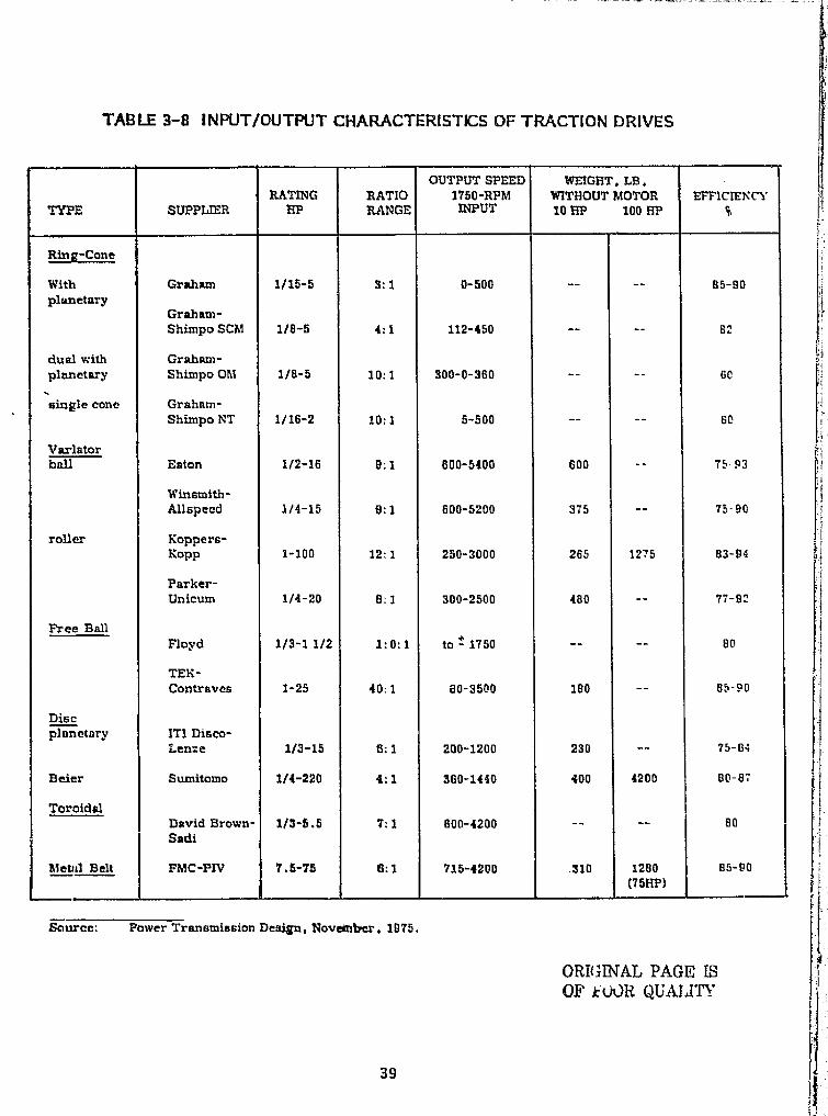
There has been a good deal of Interest and activity In the area ofcontinuously variable transmissions (CVT) within the past several years.In essence, the torque converter itself Is a form of CVT. Such mechanicalpower transmission equipment has long been available for Industrialapplications and scaled designs are being offered for vehicle use. Asummary of the state -of -the-cart In industrial traction drives is presentedIn Table 3--8. The high weight per Horsepower rating Is, generally,due to the fact that these units are packaged for Industrial, rather thanvehicular, use. However, the basic drive concepts may he applicableto the electric vtaHicle.
t !'
f
a
i -
_f
i
• i.
t
37
1 }
00
`►° 13
80 vZuj -14soLL 1LL
LLJ
40
.`d
0 400 800 1200 1600 2000 2400 2800 3200 3600
OUTPUT R.P.M.
g g000
ts.
aLLI
WiL
2401)
hCL 1600
0
Figure 3-7 Efficency and speed ratio of a typical "Detroit"automotive transmission with a torque converter. 1, 2 and 3refer to speed ratios. This data was taken at the "wide open fthrottle" condition.
r ':
5 100 ^
TORQUE ^^+^.^`® U4- ATIO EFFICIENCY 81) w
Os0
3 LLLW
2 40cr
1 20#
0 0.1 0.2 0.3 0.4 0.5 0.6 0.7 0.6 0.9 1.0
SPEED RATIO
Figure 3-8 Performance characteristics of "Hobbs" torqueconverter built by Advanced Vehicle Systems.
38ORIGINAL PAGE MDE POOR QUALITY
L r }
I,EiwY
T4. ;` TABLE 3-8 INPUT/OUTPUT CHARACTERISTICS OF TRACTION DRIVES
TYPE SUPPLIERRATING
I PRATIORANGE
OUTPUT SPEED1750-RPMINPUT
WEIGHT. LB .WITHOUT MOTOR10 HP 100 HP
EFFICIENCYQ
Ring-Cone
With Graham 1/15-5 3:1 0-500 -- -- 95-90plw3etnry
Graham-Shimpo SCM 1/8-5 4:1 112-450 -- -- 8:
dual with Graham-planetary Shimpo Ohl 1/8-5 10:1 300-0-360 60
single cone Graham-Shimpo NT 1/16-2 10:1 5-500 -- -- 6C
V arl atorball Eaton 112-16 9.1 600-5400 600 - 75-93
Winsmith-Allspeed 1/4-15 9:1 500-5240 375 -- 75-90
roller Koppers-Kopp 1-100 12:1 250-3000 265 1275 83-94
Parker-Unicum 1/4-20 8:1 300-2500 480 -- 77-92
Free BallFloyd 1/3-11/2 1.0,1 to ± 1750 -- -- 80
TEK-Contraves 1-25 40:1 80-3500 180 -- 85 90
Discplanetary ITI Disco-
Len«e 1/3-15 6:1 200-1200 230 -- 75-64
Beier Sumitomo 114-220 4:1 360-1440 400 4200 80-87
ToroidalDavid Brown- 1/3-5.5 7.1 600-4200 -- -- 80
11eWI Belt
Sadi
FMC-PIV 7.5-75 6:1 715-4200 310 1280 85-90T511P1
Scurcc: Power Transmission Desim Novemtrcr. 1975.
ORMINAL PAGE fSOF k UOR QU ATE'
39
Some of the more promising CVT's which were identified duringthe search for components are discussed in the following paragraphs.
e The basic automotive torque converter is, essentially,a CVT with slip. The Hobbs (Ref.52) design offersan efficiency of about 90% at speed ratios from 0.6 to0.95. See Figure 3 -8,
9 Excelermatic, Inc. of Austin, Texas, offers a coneroller type CVT which has been demonstrated in aninternal combustion engine vehicle (Ref. 54).Efficiencies of about 90% have been obtained above20 mph. An illustration of this transmission is given inFigure 3-9.
e A hydrostatic - gear - flywheel hybrid transmissionhas been demonstrated by SRF, Jerusalem, Israel,Efficiencies of 86 to 91% over a speed ratio of 16: 1 areclaimed.
a Hans Heynau GmbH, Germany offers a line ofinfinitely variable drives with optional electriccontrol.
One, based on a ring come traction system,is available in sizes to 5 hp and speed ratiosof 9: 1. Figure 3- 10 illustrates the mechanicalportion. Power is transmitted from the steelring which, under tension, connects each pairof steel cones on the input and output shafts.The ring rides on the surface of the cones.Variable output speeds are ?orovided by anaxial movement of the cones which arerigidly connected by the rods.
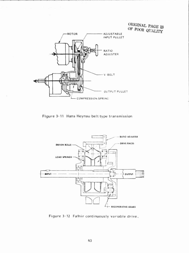
Another is a variable pitch V-belt drive whichis typical of a generic type available fromseveral other suppliers. It is rated up to 20 hpand has an adjustable speed range of 6: 1.Figure 3 - 11 illustrates the system. The outputspeed is varied by axial displacement of themovable side of the input pulley. The springloaded output pulley automatically follows thealtered effective radius. Similar systems areavailable from such domestic manufacturers asReliance Electric of Cleveland and Lewellen Man-ufacturing of Columbus, Indiana.
r,
^ r
I#:
'i r,:
40

,a.I;
M` f ? ! kZ ^,
I ^
i^
h^
t I
12 1 RATIO RANGECONTINUOUS RATIOTRACTION DRIVE
- FORWARD SERVICE CLUTCH
REVERSE SAND
_ PLANETARY REGENERATIVEGEAR SET
r+
^ 1 1
THRUST REARING -
\,— THRUST DEARING
DUAL HYDRAULIC PUMP
Figure 3-- 9 Excelermatic Transmission. A continuously variableratio of 100: 1 is achieved by coupling a traction drive to aregenerative gear set.
i}RMINAL PAGE ISt^I' YtaC}k Qljt ATy.---- STFFL RING
r _ ^
i ..
o Fafnir Bearing of New Britain, Conn., supplies amanually controlled traction drive which is used inlawn and garden tractors. It is available in sizes upto 20 hp with a 2.6:1 ratio change. Figure 3-12 illustratesthe system. The traction-drive races and regenerative sun gearare both driven by the input shaft. The traction-drive and re-generative gears have a common carrier. The traction--drive carrierratio is changed by adjusting the outer race spacing which changesthe rolling contact angles. The output ring gear speed is determinedby the summation of the sun gear and traction-drive carrier speeds.As the traction-,drive is reduced the output shaft goes to neutral and,on further reduction, into reverse.
a One of the few CVT's available with electrical controlsis offered by Electromatic Drive Corporation. Thistransmission is a variable pitch V-belt drive (based uponSalisbury Corp. components) . The pitch diameter of thedrive pulley is changed by driving a ball nut on a leadscrew by means of a hysteresis brake. The driven pulleyIs spring loaded. An illustration of the CVT is given inFigure 3-13. The Electromatic weighs 30-40 pounds, andconsumes about 5 watts of electrical power to shift.Mechanical efficiencies above 90 % are claimed and thissystem has been demonstrated in the URBA car (Ref. 55) 1-A similar electrically controlled CVT is manufactured by t +
Lovejoy, of Downers Grove, Illinois for industrialapplications. In addition, the DAF division of Volvo has hada V-belt system in the field for several years.
Hydrostatic transmissions are finding increasing application inIndustrial and agricultural machinery. They offer continuous ratiochange by varying the coupling between a hydraulic pump on the inputshaft and a hydraulic motor on the output shaft. Due to the multipletransfer- of power between mechanical and hydraulic circuits the over-all efficiency of hydrostatic drives are limited and not consideredadequate for the electric vehicle application,
The transmission plays an interacting role with the motor andcontrol system within a power train. Because of the large tirre spent jIn speed and torque change (accelerating) the relative performance oftransmissions cannot be evaluated without an analysis over a drivingcycle. Size and weight, efficient , -an a of ratio iY g y, power capability, g change, controlability and reliability are some of the general selectioncriteria. r
42
ORIGINAL PAGE ISOF POOR
QT!ALrrrADJUSTABLE
INPUT PULLET
^^._._.._..^.^_..^_-_..^..v.._....^_.^i_...^.^-^
,..max:,.., ., ^_ ^^
II^ -
'I --- LL I 1^ r I I^^u
Itu . I
RATIOADJUSTER
V BELT
OUTPUT PULLET
I NI C,
Figure 3-11 Hans Heynau belt type transmission
SAIIO ADJU$Ikk
DMVIN no"Ji /— DRFV i 111AM
LOAD PILINGS
I IOUTPUI
DC ItIOIN 11
11AIM MASS
Figure 3-12 Fafnir continuously variable drive.
43
, .N
kw _J

DRIVENASSEMBLY
RETURN-SPRING
LEAD SCREW
BALL NUT-FLANGE
FAN DISC-HUBPOLE PIECES
MAGNETIZING COIL
END PLATE
3.3.2 Differentials and AxlesORIGINAL PAGE LS
OF POOR QUALI'[Yj
41
•r.
PR MUNG PAGE BrANx Nn r
DRIVE SHAFT
HOUSING
FIXED FACESTUBBED SHAFT
Al-
MOVEABLE FACE \ -
SPRING RETAINER
PATTERN SLEEVE
OPTICAL SENSOR/r/1 ^rt 1
CABLE SOCKET
3
EXIT AIR
AIR-COOLING PORT
COOLING FAN
Figure 3-13 Electromatic V-Belt drive transmission
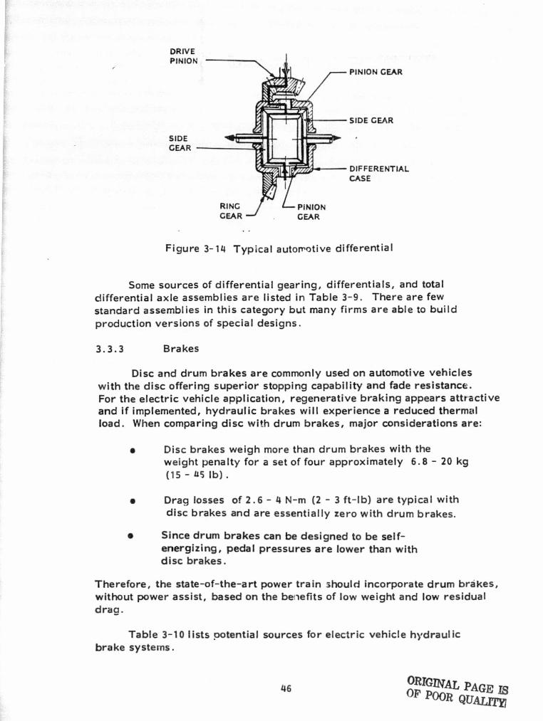
The purpose of a differential as used in a vehicle is to allowrelative motion of the drive wheels to occur during cornering. Across section of a typical automotive differential is shown in Figure 3-14.
Variations of this standard type of differential, which are withinthe state-of-the-art and applicable to electric vehicles, include thefo!lowing:
• Replacement of the power input bevel gear pairwith a belt drive, chain drive or spur gear pair, and
• Insertion of the differential within a transaxle housingas is typically done in some compact vehicles.
When the vehicle is not cornering, the efficiency of the matingbevel gears is irrelevant since they are not rotating relative to eachother. The major energy losses in a typical differential occur atthe power input gear pair and because of lubricant viscosity andsplash effects. When the input gear is of the hypoid type,typical overall efficiency of a differential/axle assembly atrated capacity is 92%. Chain drive or spur gear inputs yield98% efficiencies.
45
DRIVEPINION
SIDEGEAR
PINION GEAR
SIDE GEAR
DIFFERENTIALCASE
7
1 tr j i _^.•.
Figure 3-14 Typical automotive differential
Some sources of differential gearing, differentials, and totaldifferential axle assemblies are listed in Table 3-9. There are fewstandard assemblies in this category but many firms are able to buildproduction versions of special designs.
3.3.3 Brakes
Disc and drum brakes are commonly used on automotive vehicleswith the disc offering superior stopping capability and fade resistance.For the electric vehicle a pplication, regenerative braking appears attractiveand if implemented, hydraulic brakes will experience a reduced thermalload. When comparing disc xvi±h drum brakes, major considerations are:
• Disc brakes weigh more than drum brakes with theweight penalty for a set of four approximately 6.8 - 20 kg 1(15 - u5 lb) .
• Drag losses of 2.6 - 4 N-m (2 - 3 ft-lb) are typical withdisc brakes and are essentially zero with drum brakes.
t Since drum brakes can be designed to be self-energizing, pedal pressures are lower than withdisc brakes.
Therefore, the state-of-the-art power train should incorporate drum brakes,without power assist, based on the be^tefits of low weight and low residualdraa.
1 +
Table 3-10 lists potential sources for electric vehicle hydraulicbrake systems.
46 GMAL PAGE ISOF POOR QTJAIX 1
,f
I
i
t
TABLE 3-10 BRAKE MANUFACTURERS
Bendix Corporation, Goodyear Industrial BrakesSouth Bend, Indiana Berea, Kentucky
B. F. Goodrich, Gould Inc.Akron, Ohio St. Louis, Missouri
Delco Moraine, Hurst/Airheari Products Inc.Dayton, Ohio Chatsworth, California
Eaton Corporation, Mercury, Division of Apro Inc.Cleveland, Ohio Canton, Ohio
Electroid Company, Midland RossUnion, New Jersey Owosso, Michigan
Friction Products, Minnesota Automotive Inc.Medina, Ohio North Mankoto, Minnesota
Gerdes Products Company, Tool-O-MaticVandalia, Ohio Minneapolis, Minnesota
Girling Warner Electric Brake E Clutch CompanyTroy, Michigan Beloit, Wisconsin
d 1
I^
. i.
C a ^
i.
{
i
TABLE 3-9 MANUFACTURERS OF DIFFERENTIALS AND AXLES
Chrysler Corporation, K-8 Axle Co., Inc.East Syracuse, New York Los Angeles, California
Dana Corporation, Lear Siegler, Inc.Auburn. Indiana Detroit, Michigan
Eaton Corporation, Napco IndustriesCleveland, Ohio Hopkins, Minnesota
Fairfield Manufacturing Co. Rockwell International,Lafayette. Indiana Troy, Michigan
Hanaur Machine Works, Inc. Saginaw Steering Gear DivisionAvon, Minnesota Saginaw, Michigan
Holtan Axle and Transmission Co. The United Mfg, Co.Juneau, Wisconsin Cleveland, Ohio
a
i
:,^l
f
1

3.3.4 Tires
0 Rolling resistance
o Wheel and tire weight and size
Stopping performance
• Ride and handling quality
o Wet weather performance
Important parameters pertaining to tire selection for the electric { 'vehicle include:
For the preliminary design of the power train, rolling resistance, size and }weight are most significant. The other factors are strongly related tothe overall vehicle and suspension system design.
Wheel and tire weight should, obviously, be minimized for anefficient vehicle design. One way to minimize weight is to eliminate thespare tire. Firestone's ACT radial tire, with its "run-flat" capability,accomplishes this although each tire is somewhat heavier than a standardradial. Generally, weight is related to size and it would appear that smallertires and wheels ai^e optimum. However, the behavior of rolling resistancetends to cloud this choice.
Tire rolling reshAance is generally defined as the force resistingvehicle motion due to tire hysteresis and the interaction of the tire withthe road surface, It is usually expressed as resisting force per unit oftire load. Typical vaiues are .098 to .196 N/kg (.01 to .02 lb/lb) althoughdata as low as ,059 N/kg (.006 lb/lb) have been reported (Ref.39 ) . Tirecompanies obtain rolling resistance data by means of drum tests under"free rolling" or "coasting" conditions. Although most of our knowledgeof tire behavior is based on such data, there is some question {Ref. 56 )as to the validity of applying these results to the real case when torqueis transmitted through the tire to the road. Figure 3-15, for example,illustrates that the use of the "free rolling" data may be significantly inerror when calculating power losses over a driving cycle.
48
w.
ca
I'
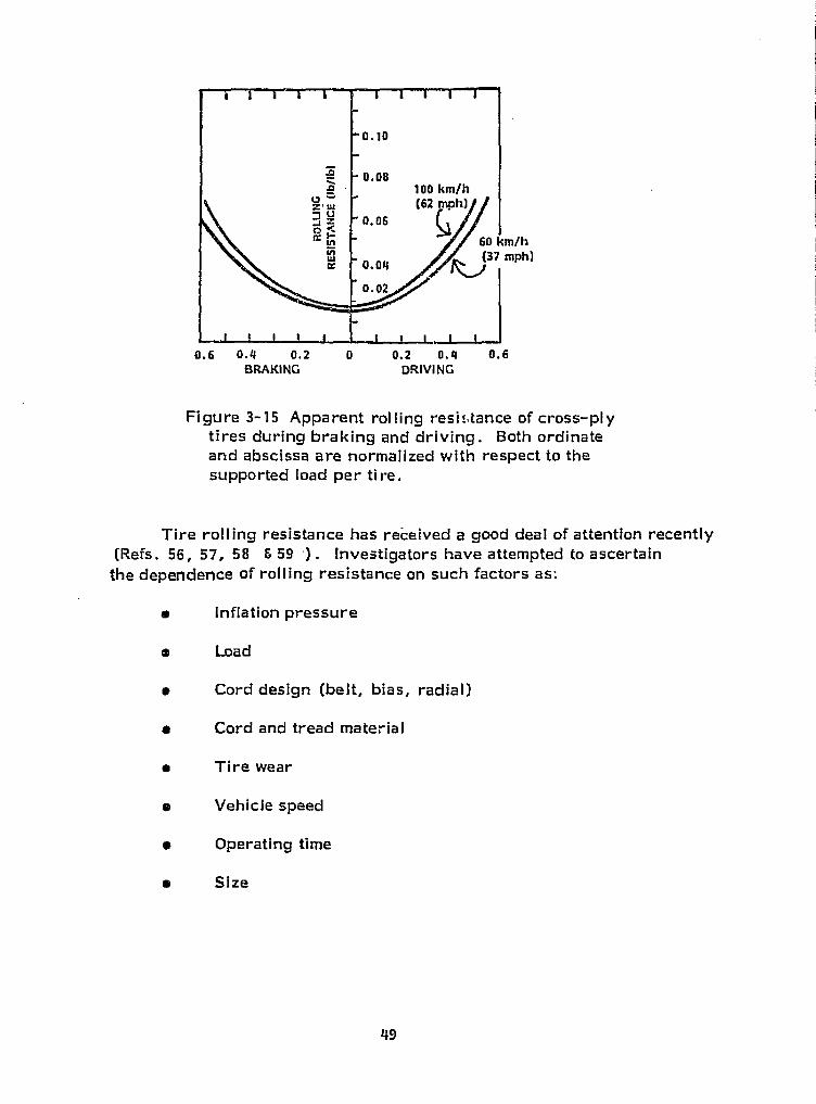
0.6 0.4 0.2 0 0.2 0.4 0.6
BRAKING DRIVING
i
Figure 3--15 Apparent roiling resistance of cross-plytires during braking and driving. Both ordinateand abscissa are normalized with respect to thesupported load per tire.
:t
Tire rolling resistance has received a good deal of attention recently f(Refs. 56, 57, 58 5 59 -) . Investigators have attempted to ascertainthe dependence of rolling resistance on such factors as:
o inflation pressureI^
a Load
o► Cord design (belt, bias, radial) i
o Cord and tread material #°i
o Tire wear
a Vehicle speed
• Operating time
• Size
a.
49
n,t:
f:
C?ti
Figures 3-16 through 3-20 present the results of some of this research.j It should be noted from this data thaftire rolling resistance:
•
i
•
•
y •
s
•
Decreases with increased inflation pressure(Figure 3-16),
Increases with load independently of rated capacity(Figure 3-17),
Is lowest with radial construction (Figure 3-18),
Decreases as wear increases (Figure 3-18),
Increases with vehicle speed in a nonlinear- manner(Figure 3-18),
Decreases assymptotically to an equilibrium valueas operation time increases (Figure 3-19) ,
Is independent of tire size (Figure 3-20) , and
Is independent of cord material (Ref. 59) .
Goodyear has recently announced the development of an "elliptic"tire (Ref. 60 ) which features.
•
•
•
•
An elliptical sidewall profile
Of steel belted, polyester carcass, radial construction
A relatively low, 65, aspect ratio
A high inflation pressure (typically 35 psi) .
Rolling resistance as much as 34 percent lower thanstandard radials.
This tire may be epplied to 1980 model automobiles. ts
50
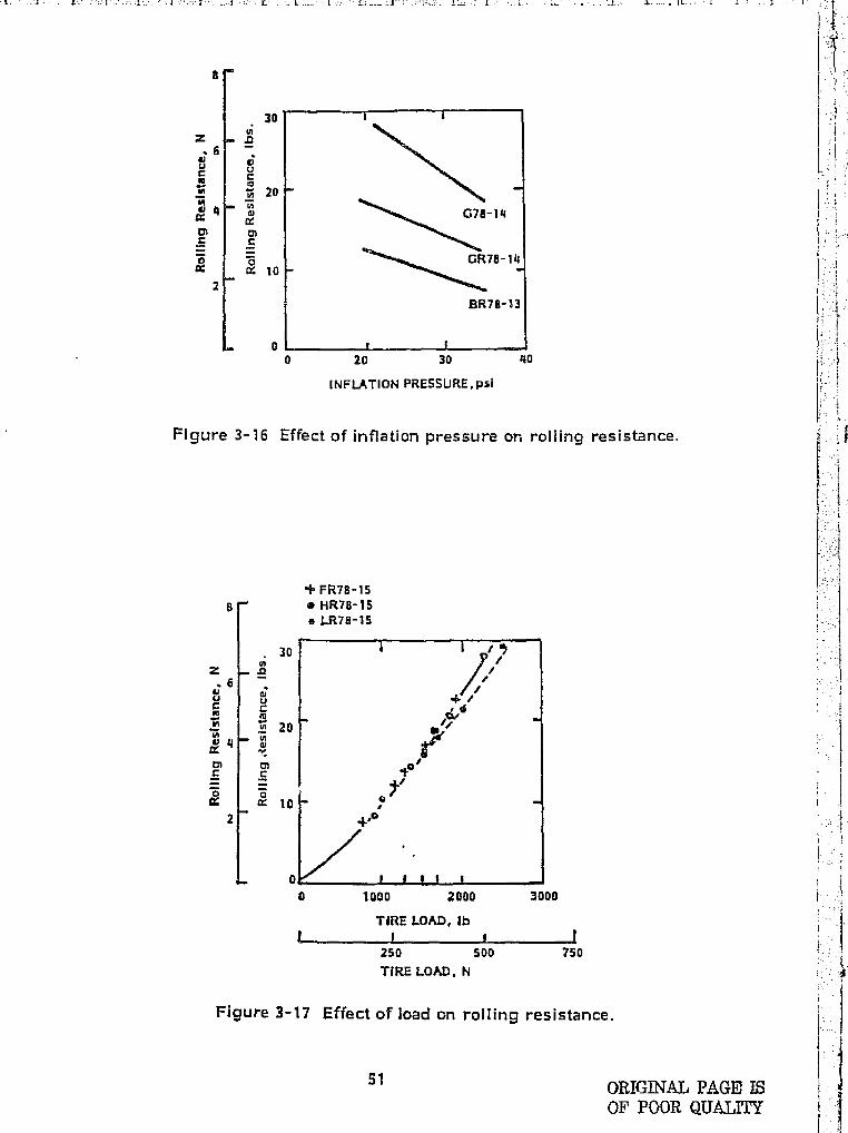
^ 1Cn C
I = 102
o'
Y4
}1p
a a
U UG ^W y„ m 20
g q m
s`' o
a 10+ 2
0
30
a
0 20 30 40 :y {
INFLATION PRESSURE,psi y•.
Figure 3-16 Effect of inflation pressure or, rolling resistance..
'$ FR78-158
m HR78-15
a LR78-15
Z .0
. 30
^ru tiuu
1
..F rU1 20
H q
OK i r t I I I
0 1000 2000 3000
TIRE LOAD, Ib
250 500 750
TIRE LOAD, N
Figure 3-17 Effect of load on rolling resistance.
51
ORIGINAL PAGE ISOF POOR QUALMY
r

0. 024
A0.010
usUzE4 0.016m
LUtr
x 0.012
0
0.002
BIAS
RADIAL
NEW ^.
r..^..^^.. ^....^ r.r RADIAL
f BIASWORN
20 40 5o so 100 120 149 160
SPEED (KPH ►L ) I I ( I0 20 40 60 s0 100
SPEED (MPH)
Figure 3-18 Rolling resistance versus speed for several tire types.
1030
026
A
A .022
WUZQFsnrq .012to
UzJ
0100
I Warmup (kilo mlars) 1I I 1
0 30 100
Warmup (miles)
Figure 3-14 Effect of warmup distance on roiling resistance of a tire.
AO B0 120 16
52
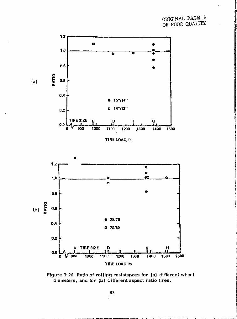
12
1.0
Q{a) d a.6
aG
0.4
1.2
1.0
am
0Cl]) ^ '^.^
CA
02
A TIRE SIZE D G Hao
0 V goo 1000 1100 1200 1300 1400 1500 1600
T113E LOAD. Ib V
Figure 3-20 Ratio of rolling resistances for (a) different wheel jdiameters, and for (b) different aspect ratio tires.
53
wig s►l.-.... .L_... _ .l _ _ .... A_. t _..' ..k '... _ 1. 8. _. L. .. S. 1 .. 1.... _. . T
Some potential sources for tires are listed in Table 3-11. Represen-tative rolling resistance values are presented in Table 3-12. /analysis ofthe data indicates that a value of .098 N/kg (0, 01 lb/lb) is a reasonablevalue for a state-of-the-art radial tire. In general, tires for the electricvehicle should be:
Of radial construction,
B With load capacity well in excess of thatrequired to support the vehicle, and
• Inflated to the maximum safe pressure.
3.3.5 Bearings
Standard engineering practice is to use rolling element bearingsto support the wheels, axles and shafts which are part of a vehicle powertrain. !E=xperience has shown that compared to bushings, which,involve relative surface-to-surface motion and fluid film bearings(hydrodynamic or hydrostatic), the lubricated roiling element bearingoffers a good compromise between:
e Load capacity,
e Friction,
0 Lubricant supply power,
0 Size,
0 Wear, and
a Cost
Typical overall values of friction coefficients (ratio of friction forceper pound of load) for roiling element bearings are:
a Self aligning ball bearings - .0010
a Thrust b0l bearings - .0013
a Single row ball bearings - .0015
a Tapered roller bearings .0018
54
C3 -1
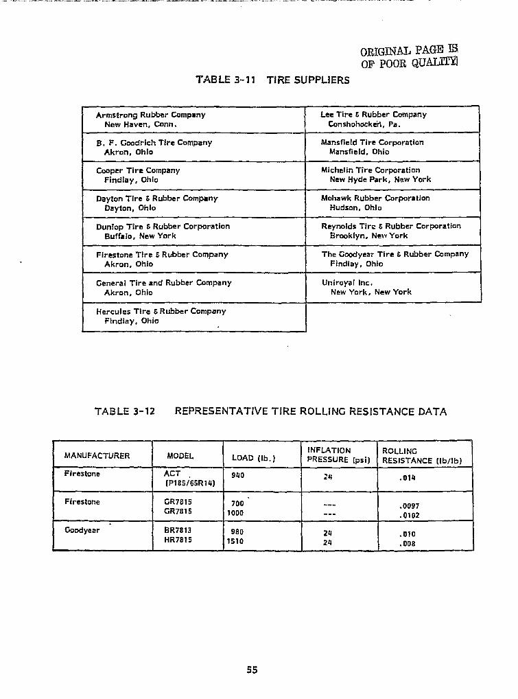
TABLE 3-11 TIRE SUPPLIERS ".
Armstrong Rubber Company Lee Tire E Rubber CompanyNew Haven, Conn. Conshohocken, Pa.
H. F. Goodrich Tire Company Mansfield Tire CorporationAkron, Ohio Mansfield, Ohio
Cooper Tire Company Michefin Tire CorporationFindlay, Ohio New Hyde Park, New York
Dayton Tire S Rubber Company Mohawk Rubber CorporationDayton, Ohio Hudson, Ohio
Dunlop Tire 6 Rubber Corporation Reynolds Tire E Rubber CorporationBuffalo, New York Brooklyn, New York
Firestone Tire E Rubber Company The Goodyear Tire f Rubber CompanyAkron, Ohio Findlay, Ohio
General Tire and Rubber Company Uniroyal Inc.Akron, Ohio New York, New York
Hercules Tire b Rubber CompanyFindlay, Ohio
i o{
r
}
f5 !.:
^ r
I^ rTABLE 3-12 REPRESENTATIVE TIRE ROLLING RESISTANCE DATA t
INFLATION ROLLINGMANUFACTURER MODEL LOAD (Ib.) PRESSURE (psi) RESISTANCE (Ib/Ib)
Firestone ACT 940R4 .014
(P185/65R14)
Firestone CR78 f 5 700 --- .0097GR7815 1000 --- .0102
Goodyear BR7813 980 24 .010HR7815 1510 24 .008
i
Fy,
f
it l
55
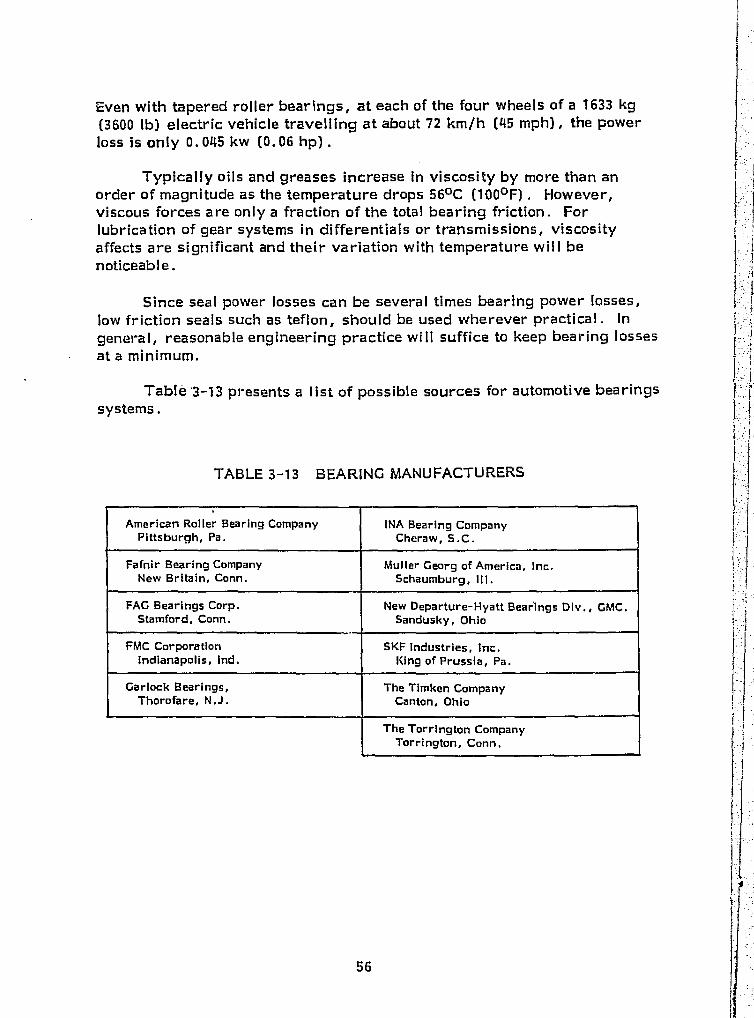
American holler Bearing Company INA Bearing CompanyPittsburgh, Pa. Cheraw, S.C.
Fafnir Bearing Company Muller Georg of America, Inc.New Britain, Conn. Schaumburg, 111.
FAG Bearings Corp. New Departure-Hyatt Bearings Div., GMC,Stamford, Conn. Sandusky, Ohio
FMC Corporation SKI= Industries, Inc.Indianapolis, Ind. King of Prussia, Pa.
Garlock Bearings, The Timken CompanyThorofare, N.J. Canton, Ohio
The Torrington CompanyTorrington, Conn,
TABLE 3--13 BEARING MANUFACTURERS
Even with tapered roller bearings, at each of the four wheels of a 1633 kg(3600 lb) electric vehicle travelling at about 72 km/h (45 mph), the powerloss is only 0.045 kw (0.06 hp) .
Typically oils and greases increase in viscosity by more than anorder of magnitude as the temperature drops 560C (1000F). However,viscous forces are only a fraction of the total bearing friction. Forlubrication of gear systems in differentials or transmissions, viscosityaffects are significant and their variation with temperature will benoticeable.
Since seal power losses can be several times bearing power losses,low friction seals such as teflon, should be used wherever practical. Ingeneral, reasonable engineering practice will suffice to keep bearing lossesat a minimum.
Table'3-13 presents a list of possible sources for automotive bearingssystems.
56
Q..
4.0 STATE-OF-THE-ART DOWER TRAIN DESIGN
Having reviewed the state-of-the-art in electric vehicle power traindesign, this chapter presents a preliminary design based upon that tech-nology. Several candidate power train configurations are discussed andare evaluated using a computer simulation. Finally, a power train whichrepresents the state-of-the-art is described and its performance is pre-dicted.
4.1 RF IUIREMENTS
The terms of the contract required that a "state-of-the-art" powertrain should consist of componerits which:
a Are available off-the-shelf or by special order withoutrequiring developmental engineering, but
0 May involve design changes to facilitate mounting withoutaffecting the intended basic function.
In addition to employing "state-of-the-art" hardware, as defined above,the electric vehicle power train design must also fulfill a set of performancespecifications, which were also defined in the contract. These are consideredrepresentative of typical urban passenger vehicle usage and are stated as follows:
ao The SAE J227a Schedule D driving c ycle (See Ref. 61
• A top speed of at least 88 km/h (55 mph) .
a The ability to climb a 10% grade at a constant 48 km/h(30 mph) speed.
The design approach taken was to maximize range over the SAE drivingcycle. A selected power train must be capable of the top speed .and the hill climb, but range over the cycle was used as the overallmeasure of power train efficiency. E
1.
57
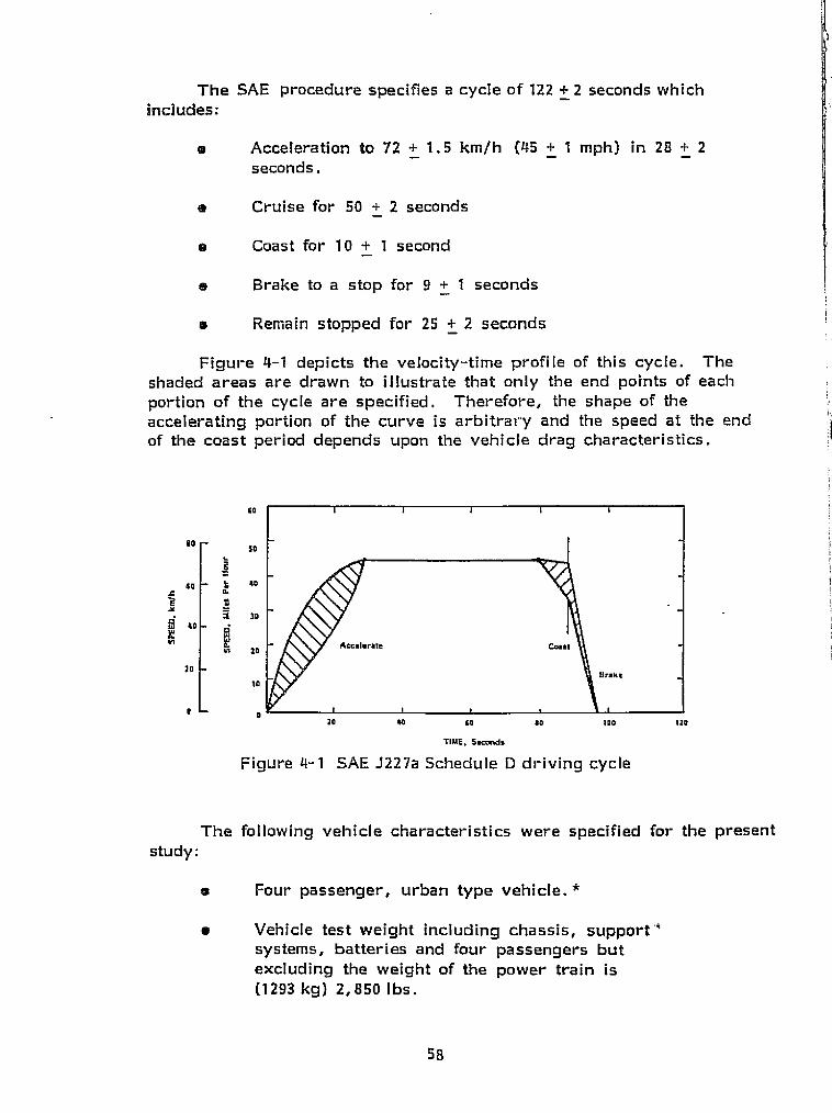
58
tj
.. ^ ^I I._- __i - -.
The SAE procedure specifies a cycle of 122 + 2 seconds whichincludes:
® Acceleration to 72 + 1.5 km/h (45 + 1 mph) in 28 + 2seconds.
ea Cruise for 50 + 2 seconds
a Coast for 10 + 1 second
Brake to a stop for 9 + 1 seconds
o Remain stopped for 25 + 2 seconds
Figure 4-1 depicts the velocity-time profile of this cycle. Theshaded areas are drawn to illustrate that only the end points of eachportion of the cycle are specified. Therefore, the shape of theaccelerating portion of the curve is arbitrary and the speed at the endof the coast period depends upon the vehicle drag characteristics.
RO
!!sa
so L +0r aE ^Y -
^ 30
IN 20
70
t0
fAccalerJfle Cwst
8nke
ZO b w so too Izo
TIME, 5aconds
Figure 4-1 SAE J227a Schedule D driving cycle
The following vehicle characteristics were specified for the presentstudy:
A Four passenger, urban type vehicle. *
a Vehicle test weight including chassis, support"systems, batteries and four passengers butexcluding the weight of the power train is(1293 kg) 2,850 Ibs.
16 EV - 106 batteries
- 11.7 w-h/lb. , 6B lb. /battery1.04 w-h/in 3 , 734 In3/battery
-- 96 volts DC system
Operating temperature = 70 + 10 0 F. *
Vehicle frontal area x drag coefficient = 0.56 m 2 (6 ft. 2 ) *
The power train consists of the motor, controller, transmission,differential, axles, couplings, brakes, wheels and tires for four wheels,and any associated cooling equipment.
4.2 PRELIMINARY COMPONENT SELECTION
On the basis of the definition of "state-of-the-art" (SOA) hard-ware and the review of electric vehicle power trains (Chapter 3.0) manyelements of the SOA system can be selected. The following paragraphsidentify those components generically and outline a methodology forcompleting the preliminary design.
The series wound DC motor and chopper type controller are wellsuited to electric vehicle (EV) power trains. The technology of DCmotors and SCR type controllers is mature and has been successfullyapplied to many electrically powered vehicles. An industrial infra-str.ucture.exists to service these systems which are relatively simple tounderstand. The motor can be designed to meet a large variety ofspecialized requirements using well known techniques and hardware. Inaddition, the solid state controller is inherently capable of highreliability and low cost. Motors are available in the range of powerrating which can fulfill the electric vehicle requirements. An analysiswill be presented in a later section to size the motor.
Although shunt wound DC motors and AC motors are available inthe basic rating needed for an electric vehicle, there are no off-the-shelfcontrollers for these motors. Hence they cannot be applied to a state-of-the-art design as defined herein.
Several mechanical transmissions are potentially suitable for electricvehicles. In general, recent consumer buying trends preclude considerationof manual gear change units. However, fixed ratio reducers, automaticgear change transmissions or continuously variable transmissions (CVT)are candidates. Versions of each of these types have been demonstratedin electric vehicles.
* Per specification in contract statement of work.
l; t
f,
r
i -
59
CD
t,
r'f
Mechanical elements such as gearing, differentials and tiresare available which offer improved efficiency over those which havebeen used in conventional vehicles. In general, these utilize rollingelement bearings and high efficiency gearing. Tires of radialconstruction, sized with high overload capacity and with high inflationpressures, offer the lowest rolling resistance.
The rear mounted motor/transaxie or the front wheel drive arepreferred power train architectures. The most common, and practicalapproach to packaging the propulsion batteries has been to employ acentral tunnel. Thus a central drive shaft is not feasible. The frontwheel drive package, which is popular on many foreign internal com-bustion engine vehicles, and the rear- motor/ transaxle, typified by theCorvair, are two practical alternates. The selection of either approachhas little bearing on the efficiency of the power train design andshould be made by the vehicle designer.
The combination of motor, controller and transmission forms a veryinteractive system. The characteristics and efficiencies of these componentsvary significantly over a typical driving cycle. Even a basic designapproach such as whether to use a fixed or changeable transmission ratiocannot be decided on the basis of simple efficiency considerations or intuitiveengineering judgement.
Consider, for example, the extreme case of a CVT versus a fixedratio reduction. The CVT will allow motor operation in its high efficiencyrange, will require less control range of the motor, and hence a simplercontroller, but it is not clear whether the added weight penalty of theCVT can be offset through performance gain. The goal is to maximizethe range over the driving cycle. The: battery and motor sizing entersinto this analysis due to the high current draw typical of grade climbingand acceleration at Iow motor speeds.
Further implications of the need for a careful, and objective trade-off analysis can be seen when considering the concept of individualwheel motors. At first it appears that such an approach is not desirableon the basis of efficiency because motor losses (i.e., end turn losses)and transmission losses will be greater for the multiple motor design.However, if fixed ratio reduction is feasible, then lightweight, highspeed, wheel mounted motors, which are individually controlled maybecome viable.
The selection of an optimum power train requires a systemsanalysis of the hardware operating over the driving cycle. There-fore, the next section describes the analytical model to be used for thisstudy.
60
^s
i
ORIGINAL PAGE IS
Of, POOR Qumff y
-.^ 4.3 ANALYTICAL_ MODELe
As part of work performed for the Environmental Protection Agencyunder Contract No. EPA-460-3-74-020 and for ERDA under Contract No.
E E(04-3)-1180, the General Research Corporation (GRC) of Santa Barbara,California developed a computer program for analyzing the performance
r = of electrically powered vehicles. This GRC software was employed int `. the present study.
4.3.1 Component Mathematical Models
The propulsion system must provide the tractive effort to over-come the total "road load" on the vehicle and the losses associated withthe power train. For a pure electric vehicle the energy required is
_
supplied by the storage batteries. 'The calculation of range proceedsby accounting for this energy consumption as the vehicle operatesrepeatedly over a driving cycle until the batteries can no longerdeliver the required power. The power calculation procectes from theroad load to the battery as depicted in f = igure 4-- 2. The followingparagraphs summarize the algorithms used in the GRC model.
j
^i
I
f.b•
3
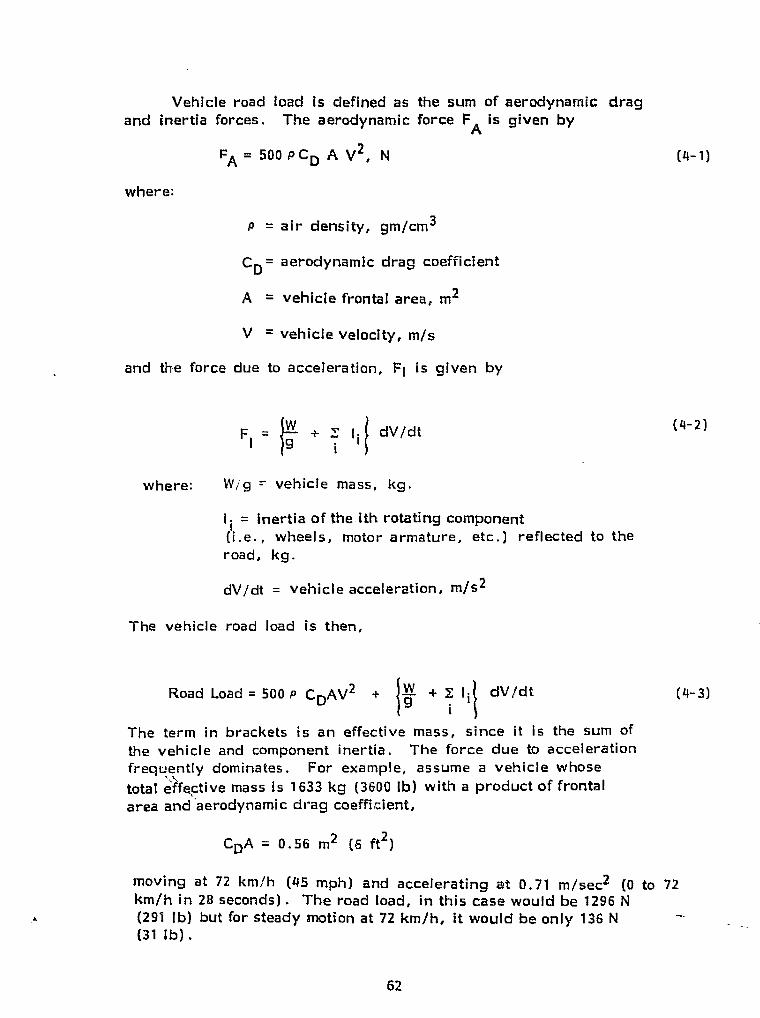
` r
Vehicle road toad is defined as the sure of aerodynamic dragand inertia forces. The aerodynamic force FA is given by
FA = 500 ACp A V 2 , N (4-1)i
where:l
t j
= air density, gm/cm3`
C = aerodynamic drag coefficient
A = vehicle frontal area, m2
V = vehicle velocity, m/ s
and the force due to acceleration, Fl is given by
F = w : ^' 1. dV/dt ( - z)
r
W = vehicle mass k .where: ^ g g #
I Inertia of the ith rotating componentS
(i.e., wheels, motor armature, etc.) reflected to the7 road, kg.
dV/dt = vehicle acceleration, m /s2a
The vehicle road load is then,. 1
Road Load = 500 P CpAV 2 + 9 + El i dV/dt (4-3)i
The term in brackets is an effective mass, since it is the sum ofthe vehicle and component inertia. The force due to acceleration r
i_ frequently dominates. For example, assume a vehicle whosetotal effective mass is 1633 kg ( 3600 lb) with a product of frontal iarea and `aerodynamic drag coefficient, ,1 ii
1 C A = 0.56 m 2 (5 ft2 )D ►:. r..:.f
.l t
moving at 72 km/h (45 mph) and accelerating at 0.71 m/sect (0 to 72l ' km/h in 20 seconds) . The road load, in this case would be 1296 Nc (291 lb) but for steady motion at 72 km /h, it would be only 136 N
(31 ib) .
62
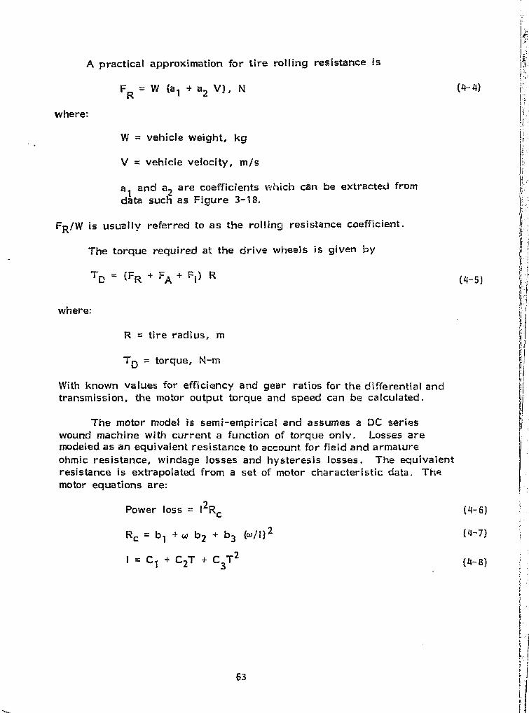
i(4-6)
(4-7)
A practical approximation for tire rolling resistance is
FR = W (a , + a2 V) , N
(4-4)
where:
W = vehicle weight, kg
V = vehicle velocity, m/s
a t and a2 are coefficients vdhich can be extracted fromdata such as Figure 3-18.
FR/W is usually referred to as the rolling resistance coefficient.
The torque required at the drive wheels is given by
TD = (FIR FA + F l ) R(4-5)
where:
R = tire radius, m
TD = torque, N-m
With Known values for efficiency and gear ratios for the differential andtransmission, the motor output torque and speed can be calculated.
The motor model is semi-empirical and assumes a DC serieswound machine with current a function of torque oniv. Losses aremodeled as an equivalent resistance to account for field and armatureohmic resistance, windage losses and hysteresis losses. The equivalentresistance is extrapolated from a set of motor characteristic data. ThRmotor equations are:
Power loss = 12Rc
Rc = b i + w b2 + b3 (wj1)2
1 = C 1 + C 2 + C3T2
63
f
^f
i
a.
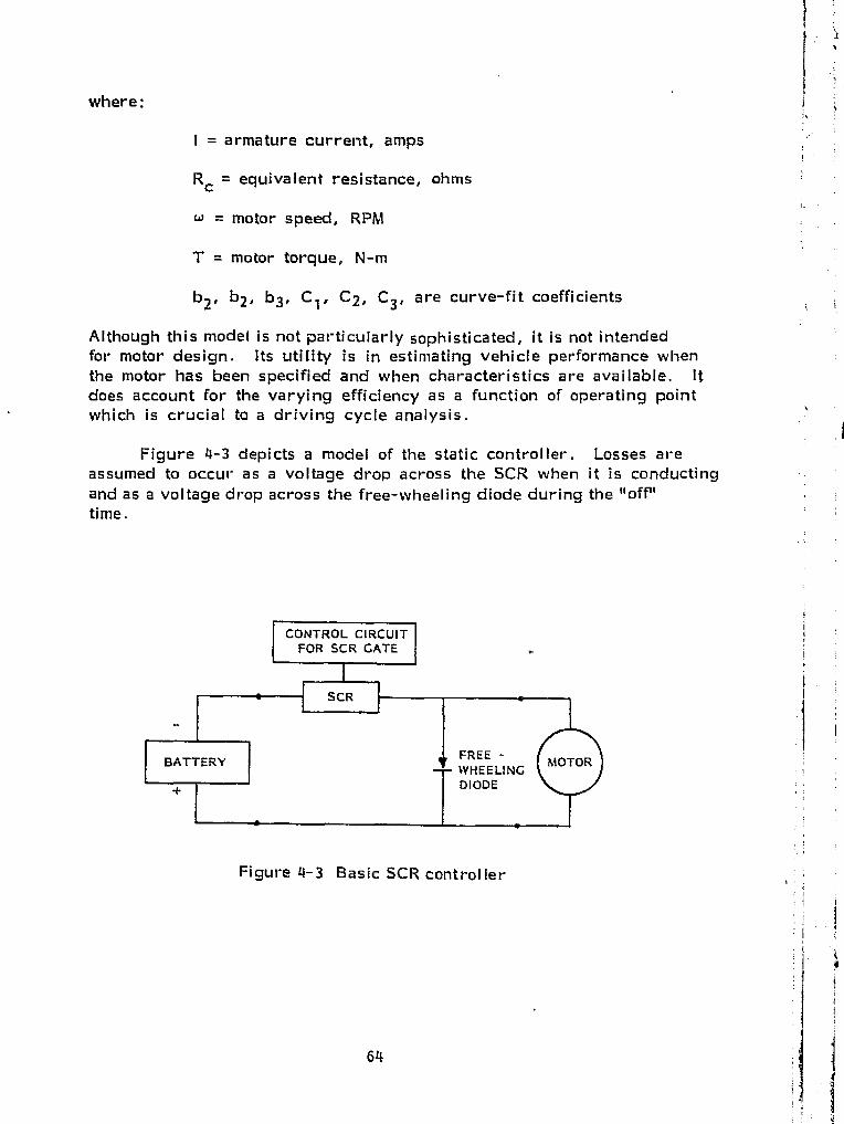
r
5
CONTROL CIRCUIT IFOR SCR GATE E
! SCR f
BATTERYFREE - MOTOR
TWHEELINGDIODE
Figure 4-3 Basic SCR controller
64
JW
f f
where;
I = armature current, amps
Rc = equivalent resistance, ohms
w = motor speed, RPM
T = motor torque, N-m
b2 , b2 , b3 , C i f C2 , C 31 are curve-fit coefficients
Although this model is not particularly sophisticated, it is not intendedfor motor design. Its utility is in estimating vehicle performance whenthe motor has been specified and when characteristics are available. Itdoes account for the varying efficiency as a function of operating pointwhich is crucial to a driving cycle analysis.
Figure 4-3 depicts a model of the static controller. Losses areassumed to occur as a voltage drop across the SCR when it is conductingand as a voltage drop across the free-wheeling diode during the "off"time.
Range Is calculated by depleting the energy stored in thebatteries until the vehicle cannot operate over the driving cycle.There are several battery models available. For example:
Q The Kleckner algorithm based on Peukert;sequation (Ref. 48) ,
0 The Hoxie algorithm based on work conducted byTaylor and 5inek which allows for recuperationeffects (Ref. 49 ), and
The fractional utilization algorithm based on theRagone plot (i.e., plot of specific energy densityversus specific power density) (Ref, 62 ) .
The fractional utilization model, which is a simple nattery depletion( algorithm, agreed well with test data (Ref. 62) and was employed for
the present study. It has been reported (Ref. 5 ) that the apparentcapacity of a battery may increase when regeneration is included.Polarization and sulphation are suspected to be responsible for thisenhanced regeneration. A recent investigation into the pulsed dischargecharacteristics of lead-acid batteries (Ref. 51) suggests that similar
` "recovery" between pu lses may account for an increase in capacityIn some cases. Experiments presently underway at NASA-LERC mayhelp to Increase our understanding of battery behavior. The presentinvestigation includes an enhanced regeneration utilization factor of1.99 (Ref 5 ) as an upper bound on range over the driving cycle.A lower bound is given by ignoring this enhancement and accountingonly for the energy regenerated with a 75% efficiency.
4.3.2 Computer Program Description
The computer program simulates the operation of an electricallydriven vehicle by a sequence of time -velocity pairs. For each timestep specified by the user, the model determines the torque requiredfrom the motor to move the vehicle which in turn determines the powerrequired from the battery to produce this torque. The distancetraveled by the vehicle and the quantity of energy removed from the batteryduring the time step are computed and added to the distance traveled andenergy used in the previous time steps. Wher, the driving cycle is completed,She distance traveled by the vehicle over the one cycle and the amount ofenergy removed from the battery is used to estimate the total range of thevehicle.
As shown In Figure 4-4 the program consists of several sub-routines which are described below:
a^
I
65
I
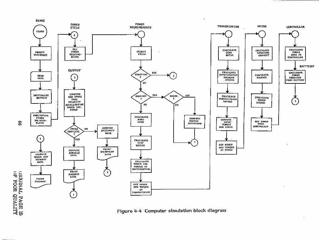
v`
t
i
ELVECCYLg POWER
TAANSMISsIOR MOTORCYCLE REQUIREMENTSCOHTAOLLER h.---^-^
iSTART I
2
iGET
PRESIT POWER SELECT CAGF.AP. TB
CARIATURECALCULATE
I VARIABLES REQUIRE- CYCLE. RATIO CURRENT Loss in
E
^ HI.FiTS CONTROLLER f^T
BATTERYY
OUTPUTYES CALCULATE CALCULATE
READ COASTING INPUT/OUTPUT CALCULATE POWERDATA 3 ? ANGULAR VOLTAGr. REOUTAED
SPFEOS TAO" UATTERY !i NO
i
INITIALIZE AND STORE BRAKING YES RECFH. YES CALCULATE CALCULATETIME7 ? TRANSvISSION MOTOR •-
J VELOCITY IASSES
LOSSES IrACCELERATION NO "DRANGE INC.
. - POKER R-- -...---
PREC7HPDTE CAI.CULATF. .PGII£R COHPUTF -CR REI UIRF.- LOAD ENERGY
COMPUTE GPr POWr
iCT "Ts RFCOVF.NFD TOROUC FROM
1 CYCLE NO COMPUTE AND PrMrR CONTROLLER
CUHPLETE IHCRCMrHT -? DATA
I YES CALCULATETIRE
LGSSFS GET POWER -AND TORQUE{J PRINT
j -111-E ATAT HOTOR
RTfiGF, Alin rAVF.NACE`
CCNIPUTE DATA DATA
i SU'* ARYi DATA CALCULATE
POWER AND ^---^•r'•TORQUE ATDIFFFRENTIAL
4 `.. PRINT 2
I x DATAImo. AVERAGE
R"I PRINT_SIR I2j;T
GET Pnw1:Ri O AND TOR011F. =:
ATTRAII.SNTSSTnN F -^~
55
Mf=igure 4-4 Computer simulation block diagram
i
:
L
I3 !p
The input routine (ELVEC) reads in the data required torun the model and initializes calculations. In addition,this routine also checks the validity of the data. Inputdata requirements include:
- Vehicle characteristic data, such as vehicleweight, aerodynamic drag, transmission/differential efficiency, number of gears and'r'jgear ratios, motor data and controller data;
- Battery data, such as battery weight, batterypower and energy density, number of batteries,number of cells per battery and battery cell Evoltage; {
- Mission profile data, such as the speed of thevehicle and the grade for "constant speeds'runs or the driving cycle the vehicle is tobe simulated on for non-constant speed runs. j
a The load routine (POWER REQUIREMENTS) Serves to calculate thetorque required to drive the vehicle. Using data on the effi-ciency of the driveline, the model accomplishes this by computing:- The forces exerted on the vehicle due to aero-
dynamic drag, tire rolling resistance andacceleration; r
- The torque and speed required to drive the .'wheel s;
- The torque and speed required at the input to ..,:the differential and transmission.
The forces exerted on the vehicle, and the power requiredat the wheels and transmission, are based on standardengineering relationships as described in the previous.sections.
I.0 The MOTOR and CONTROLLER routines model the electric motor and
solid state controller. The basic functions of the routine are:
To calculate the armature current, equivalentresistance and applied terminal voltage requiredto match the power input to the transmission;
- To calculate the motor and controller losses;
67
-- To calculate the required battery output based onthe above two factors plus motor speed and thetorque required to drive the vehicle (i.e., theoutput of the load routine) .
The electric motor is modeled as a direct-current serieswound machine and the solid state controller as a"chopper" type controller.
0 The BATTERY discharge routine simulates the depletion ofenergy from the vehicle's battery. The basic outputs ofthis routine are the power discharged from the batteryand quantity of energy consumed. In addition, this routinealso simulates battery recharge during vehicle braking(i.e., regenerative braking) if desired.
n
The OUTPUT routine compiles and prints out statistics re-garding the performance of the vehicle. Primary out-puts of the model include:
The distance traveled (range) by the vehicleduring the driving cycle selected and theprojected range of the vehicle assuming thevehicle was operated repeatedly over thedriving cycle until total battery depletion;
- A summary of aerodynamic road load, transmissionand motor/controller losses;
- A summary of vehicle speed, road load, motorspeed, current and voltage, transmissionefficiency, motor/controller efficiency, overallefficiency and battery power used, with respectto time;
- The energy efficiency of the vehicle.
The GRC model was applied to calculate the range of an idealvehicle, to perform a sensitivity analysis, to aid in sizing the motorand to evaluate candidate power train configurations.
Since the computer model requires a set of velocity-time pairs,and since the SAE driving cycle only specifies the and points of theaccelerating portion (0 to 72 km/h in 28 seconds) , some choice for thevelocity profile must be made.
One choice is to use a constant acceleration of:
72 km/h 0.71 m/s228s
Alternatively the 28 second period could be divided into several timeintervals each with its own constant acceleration. Using this method,a continuous function was selected which represents reasonable driveraction. Such a profile is illustrated in Figure 4-5.
14A,— With Constant>. Acceleration
me
Figure 4-5 - Exponentially decreasing acceleration profile forSAE driving cycle.
69
.
L
4
f
II The coefficients for this profile are set by the following conditions: J}f
0 The area under all acceleration profiles must be the samesince a given velocity must be reached In the same time. j
o The final acceleration is selected, arbitrarily, at 50% ofthe constant acceleration of 0.71 m/sZ
For the SAE cycle the initial acceleration is approximately0. 125 G and at 72 km/h the acceleration drops to 0.037 G.
i {{1
With the exponential profile the power drain from the batteryIs more nearly constant when compared to the constant acceleration -case. f= igure 4-6 illustrates this point for a typical simulation run.
50
CONSTANTACCELERATION-
40
BATTERY
EXPONENTIALLYDRAIN
DECREASING11:11)
ACCELERATION
30
20
10
5 14 is 20 25 30Time, Seconds
Figure 4--6 - Battery drain with different acceleration profiles.
The area under these two curves is approximately equal since itrepresents energy consumed. The acceleration profile would notaffect energy drain directly but since higher speeds are associatedwith greater motor windage and aerodynamic friction one might anticipatea small difference in favor of the constant acceleration profile. However,
K _
70
since the vehicle travels farther with the exponential profile and becauseof the desirability of using the battery at constant power drain, the expo- inential profile is preferred. Simulations have shown that the exponentialprofile improves range over the SAE cycle by about 5%.
tI
4.3.4 Range of an ideal Vehicle ( ,
The total energy contained in the 16 EV--106 batteries is r0 6 batteries) x (65 lb/battery) x (11.7 watt-hr/lb) or 12.16B kwh. ? lBy assuming that the power train weighs 340 kg (750 lb) , the itotal test weight is 1633 kg (3600 lbs) . If the rolling resistance is0.098 N/kg (0.01 lb/lb) and the product of the aerodynamic drag'` I ^coefficient and the frontal area is 0.56 m 2 (per Section 4.1) the trac-tive power necessary to propel a vehicle over the SAE cycle is shown k ► ^in Figure 4-7. The power required for the 88 km/h (55 mph) cruiseand the hill climb is also indicated in Figure 4-7.
f
30
SAE J 227 SO4 grade,
20SCHEDULE U 48 km/h (30 mph)
p ^ Y
a 10 BB kmlh (55 mph)
LU
Y i$I20 40 60 104 120
LU
TIME, Seconds Braking 1
}- -20 1U
-u4
Figure 4-7 Tractive power required for a 1633 kg (3600 lb)vehicle.
1x
If we assume, further, that all other drive line elements (such asmotor, transmission, differential, etc.) are perfectly efficient therange achievable with a fully charged set of batteries can be estimated. tTable 4--1 presents the results of such a calculation. 4
71
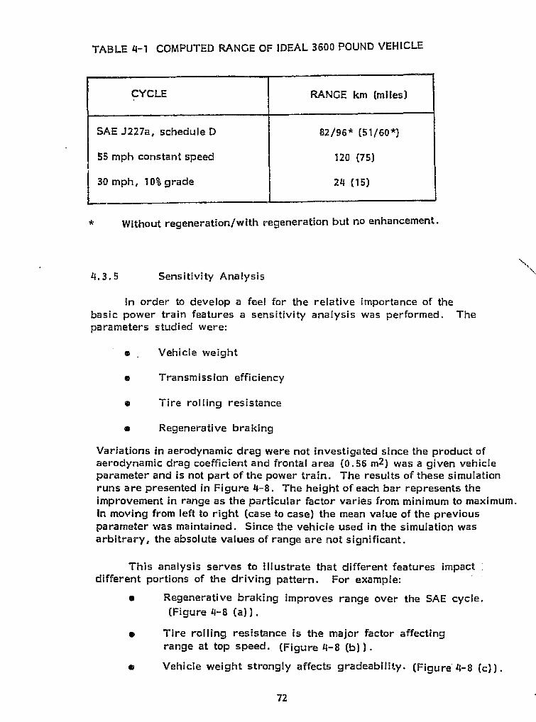
CYCLE RANGE km (miles)
SAE J227a, schedule D 82/96* (51/60*)
55 mph constant speed 120 (75)
30 mph, 10% grade 24 (15)
* Without regeneration/with regeneration but no enhancement.
4.3.5 Sensitivity Analysis
In order to develop a feel for the relative importance of thebasic power train features a sensitivity analysis was performed. Theparameters studied were:
a . Vehicle weight
a Transmission efficiency
o Tire rolling resistance
m Regenerative braking
Variations in aerodynamic drag were not investigated since the product ofaerodynamic drag coefficient and frontal area (0.56 m 2 ) was a given vehicleparameter and is not part of the power train. The results of these simulationruns are presented in Figure 4-8. The height of each bar represents theimprovement in range as the particular factor varies from minimum to maximum.In moving from left to right (case to case) the mean value of the previousparameter was maintained. Since the vehicle used in the simulation wasarbitrary, the absolute values of range are not significant.
This analysis serves to illustrate that different features impactdifferent portions of the driving pattern. For example:
• Regenerative braking improves range over the SAE cycle.(Figure 4-8 (a)) .
Tire rolling resistance is the major factor affectingrange at top speed. (Figure 4-8 (b)) .
o Vehicle weight strongly affects gradeabiliiy. (Figure 4-8 (c)) .
r72
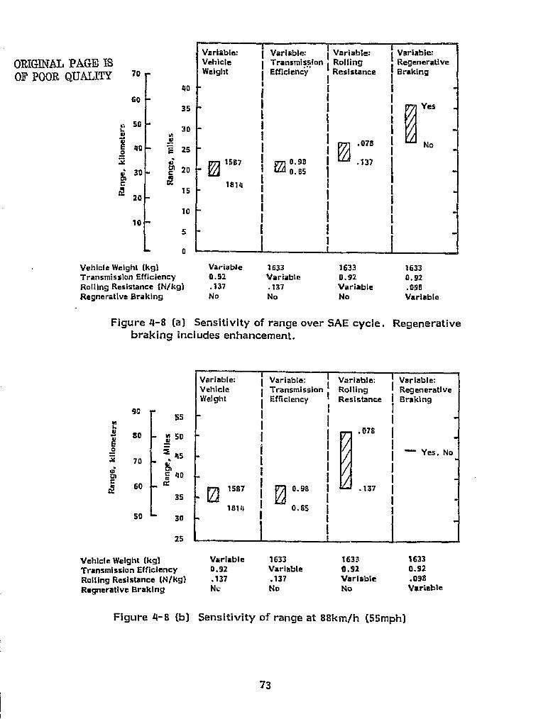
Variable: I Variable: Variable: Variable;Vehicle I Transmission Rolling RegenerativeWeight I Efficiency I
0
Resistance Braking
I .078 I
" Yes, No
1587€ i; ^ 0.98
E
181 4 ! 0.65
Vehicle Weight (kg) Variable 1633 163.1 1633Transmission Efficiency 0,92 Variable 0.92 0.92Rolling Resistance (N/kg) .137 . 137 Variable .098Ragnerative Braking Nu No No Variable
Figure 4-8 (b) Sensitivity of range at 88km /h (55mph)
3 .
a II
I
^1
i
I^
I
73
9,55
ns.
Ig0 m 50E045
70
L 60
40
35
50 L30
25
ORIGINAL PAGE ISOF POOR QUALITY 70
^o
6035
5030
M N
40 25
.Y ti
30 Cal 20
c7 1
205
10
10
5
0
YS.
IE
1
Vehicle Weight (kg) Variable 1633 1633 1633 #Transmission Efficiency 0.92 Variable 0.92 0,92Rolling Resistance (N/kg) .137 .137 Variable .098Regnerative Braking No No No Variable "1
Figure 4-8 (a) Sensitivity of range over SAE cycle. Regenerativebraking includes enhancement, I

8 r 5.0
hW
6rnC
^ Acm 3.0
4
2.0
Variable: I Variable: Variable: Variable:Vehicle l Transmission 1 Rolling RegenerativeWeight Efficiency i Resistance Braking
! j I
,075 I
! Yes. No1587 I ® 0.98
1814 I I i
l IIi l !^ I I
Vehicle Weight [kg) Variable 1633 1633 1633Transmission Efficiency 0.92 Variable 0.92 0.92Rolling Resistance [N/kg) .137 .137 Variable .098Regnerative Braking No No No Variable
Figure 4-8 (c) Sensitivity of range up a 10% grade at 413 km/h (30 mph)
In addition, the analysis is useful as a method to approximately scalecalculated range as parameters vary. For example, the sensitivityof range up a 10% grade at 30 mph to vehicle weight is approximately4/(20x500)-0.0004 mi/mi /lb., so that if a vehicle weighing 1633 kg(3600 lb) achieved a range of 2.5 miles up this grade, a similar oneweighing 1542 kg (3400 lb) should achieve about 2.7 miles (0.0004 x200x2.5+2.5).
4.3.6 Motor Sizing
The tractive power data presented in Figure 4-7 can be used toapproximately size a motor for the power train . This curve is basedon a set of vehicle characteristics which include a maximum vehicleweight and reasonable tire performance. IC should, therefore, representa worst case requirement.
To arrive at a motor size note that the 88 km /h (55 mph) topspeed requires that the motor deliver about 9 kw to the road. Byconservatively assuming an overall driveline efficiency of 50%, a motorrated at 18 kw (24 HP) can be expected to provide the 25 kw needed forthe gradeability.
74
LU 11
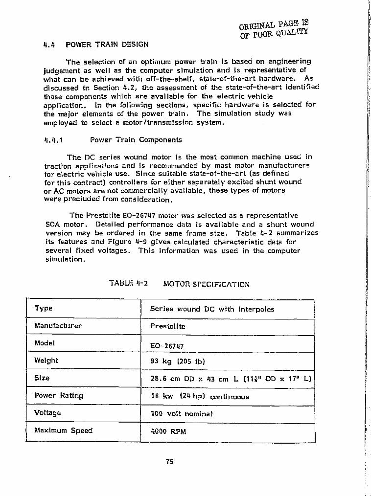
ORS OUR QUALI'YOF
4.4 POWER TRAIN DESIGN
The selection of an optimum power train is based on engineeringjudgement as well as the computer simulation and Is representative ofwhat can be achieved with off-the-shelf, state-of-the-art hardware. Asdiscussed In Section 4.2, the assessment of the state--of-the-art identifiedthose components which are available for the electric vehicleapplication. In the following sections, specific hardware is selected forthe major elements of the power train. The simulation study wasemployed to select a motor/transmission system.
4.4.1 Power Train Components
The DO series wound motor Is the most common machine uses: intraction appPica0ons and is recommended by most motor manufacturersfor electric vehicle use. Since suitable state-of-the-art (as definedfor this contract) controllers for either separately excited shunt woundor AC motors are not commercially available, these types of motorswere precluded from consideration.
The Prestolite EO-26747 motor was selected as a representativeSOA motor. Detailed performance data is available and a shunt woundversion may be ordered in the same frame size. Table 4-2 summarizesits features and Figure 4-9 gives calculated characteristic data forseveral fixed voltages. This information was used in the computersimulation.
TABLE 4-2 MOTOR SPECIFICATION
Type Series wound DC with interpolesi
Manufacturer Prestolite
Model EO-26747
Weight 93 kg [205 lb)
Size 28.6 cm OD x 43 cm L (111" OD x 17" I-)
Power Rating 18 kw (24 hp) continuous
Voltage 140 volt nominal
Maximum Speed 4000 RPM
:i 75
j,J
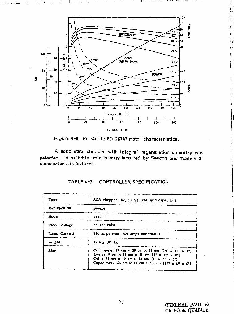
6
5
120 0so —'0 4
XZ
aD B0 3
a3: x
40
4D
20 I
0 0 0
1c1ENCY
Type SCR chopper, logic unit, coil and capacitors
Manufacturer Sevoon
Model 7650-4
Rated Voltage 60-130 Volts
Rated Current 750 amps max, 400 amps continuous
Weight 27 kg (6D lb)
5fze Choppper. 36 cm x 25 cm x 18 cm (14" x 10" x 7")Logic; 8cmx26cmx IS cm (3"x II"xe")Coil- 15 cm x 10 cm x 13 cm (6"x 4"x S")Capacitors; 25 cm x I3 cm x 75 cm (10" x S" x 6")
f}
100I + 'IE
90 ?, `U
ao Y ^ '..' t .
100 v u75 v' 7
cu
50 v 0
50
25 vIE
100 v
300
POWER 75v 1i
20050 V a
100 {i
25 v
G ^ r0 20 40 60 80 100 120 140 160 la0
Torque, ft. - rb.I I ! r i ! I i r r I f l ii ^..:^0 40 so 120 160 200 240
j
TORQUE. N-m itrt
1Figure 4-9 Prestolite EO--26747 motor characteristics.
A solid state chopper with integral regeneration circuitry was 1r,elected. A suitable unit is manufactured by Sevcon and Table 4- 3summarizes its features.
i
TABLE 4-3 CONTROLLER SPECIFICATION 1
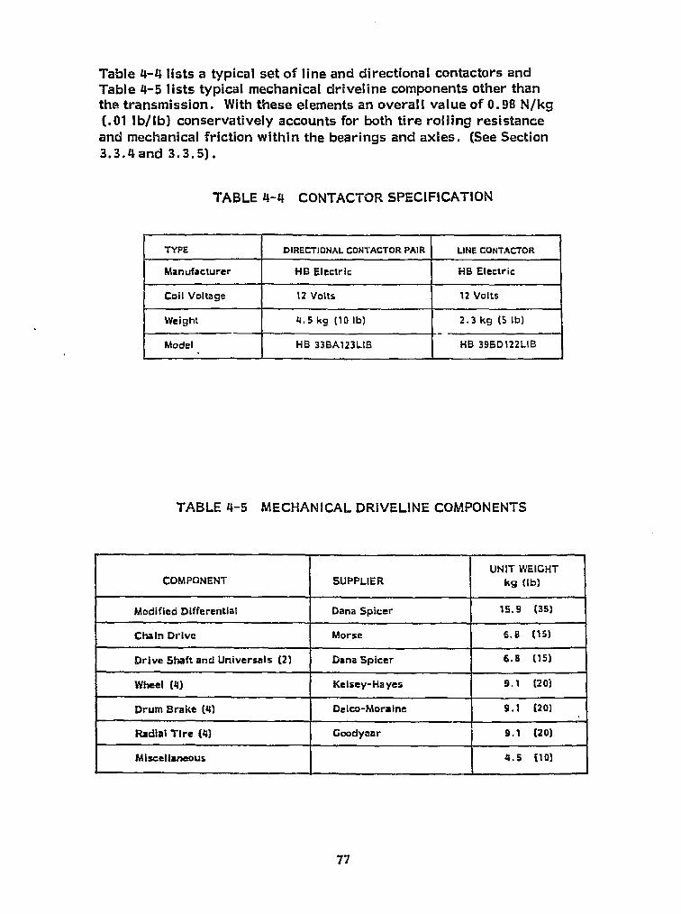
t J.. A I It. l i~ i i _..^ _' l . _ I _ ..: k Y
Table 4-4 lists a typical set of line and directional contactors and;`. Table 4-5 lists typica l mechanical driveline components other than
the transmission. With these elements an overall value of 0.98 N/kg(.01 lb/lb) conservatively accounts for both tire rolling resistance
'
and mechanical friction within the bearings and axles. (See Section3.3.4 and 3.3. 5) .
TABLE 4-4 CONTACTOR SPECIFICATION^^
^, fJ TYPE DIRECTIONAL CONTACTOR PAIR LINE CONTACTOR
Manufacturer Ha Electric HB Electric
Coil Voltage 12 Volts 12 Volts
Weight 4, 5 kg (10 lb) 2.3 kg (5 lb)
1113 39BD122LIBModel HB 33BAl23LIS
i
'T'ABLE 4-5 MECHANICAL DRIVELINE COMPONENTS
COMPONENT SUPPLIERUNIT WEIGHT
kg (lb)
Modified Differential Dana Spicer 15.9 (35)
Chain Drive Morse 6.8 (15)
Drive Shaft and Universals (2) Dana Spicer 6.8 (15)
Wheel (4) Kelsey-Hayes 9.1 (20)
Arum Brake (4) Delco -Moraine 9.1 (20)
Radial Tire (4) Goodyear 9.1 (20)
Miscellaneous 4.5 (10)
77
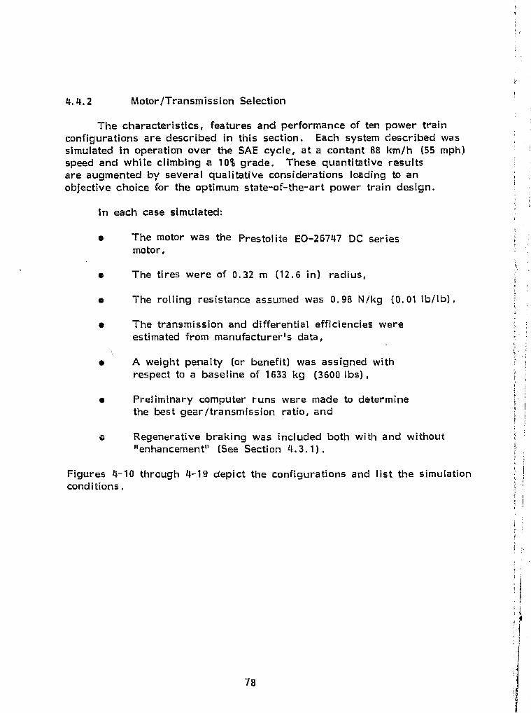
4.4. Z Motor/Transmission Selection
yi
f
1
The characteristics, features and performance of ten power trainconfigurations are described in this section. Each system described wassimulated in operation over the SAE cycle, at a contant 88 km/h (55 mph)speed and while climbing a 10% grade. These quantitative resultsare augmented by several qualitative considerations leading to anobjective choice for the optimum state-of-the--art power train design.
In each case simulated:
• The motor was the Prestolite EO-26747 DC seriesmotor,
® The tires were of 0.32 m (12.6 in) radius,
a The rolling resistance assumed was 0.98 N/kg (o. 01 lb/lb) ,
s The transmission and differential efficiencies wereestimated from manufacturer's data,
• A weight penalty (or benefit) was assigned withrespect to a baseline of 1633 kg (3600 lbs) ,
• Preliminary computer runs were made to determinethe best gear/transmission ratio, and
o Regenerative braking was included both with and without"enhancement s' (See Section 4.3.1) .
Figures 4-10 through 4-19 depict the configurations and list the simulationconditions.
78

HYPO
GEAR
TO
WHEEL
Case 1: DC motor directly coupled a hypoid differential.r (Figure 4-10) This is the most common arrangement
found on existing conversions where the internalI; combustion engine and transmission is re laced bg R Y
an electric motor. Construction is simple andrugged. However, little concern for matching motorefficiency to the load is apparent in this approach.Hypoid gearing is inefficient and efficiency is sensitiveto lubricant temperature.
OR Simulation Paraamtert
• Weight PSa:ty 0
• Overall Drive Ratio 4.2 1
a drlvelineEfficiamy 0-92
TO
WHEEL
JNIVEP.SALS
Figure 4-1C DC motor directly coupled to a hypoid differential.
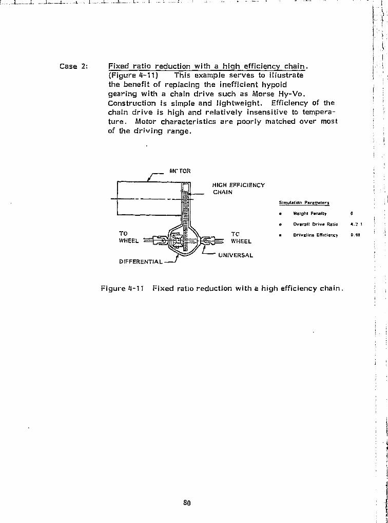
-1—, J.-
Case 2: Fixed ratio reduction with a hiclh effieiencv chain.(f= igure 4--11) This example serves to illustratethe benefit of replacing the inefficient hypoidgearing with a chain drive such as Morse Hy-Vo.Construction is simple and lightweight. Efficiency of thechain drive is high and relatively insensitive to tempera-ture. Motor characteristics are poorly matched over mostof the driving range.
me roR
HIGH EFFICIENCYCHAIN
Simulation Parameters
e Weight Penalty 0
a Overall Drive Patio 4.; t
TOTC a Drlveline ENtclency 0.92WHEEL WHEEL
UNIVERSALDIFFERENTIAL
Figure 4-11 Fixed ratio reduction with a high efficiency chain

Case 3: Dual Motor drive with fixed reduction chains. (Figure 4-12)This configuration, or an alternate using coaxial gearing, ?offers a weight advantage. The chain drive version shouldresult in the more desirable condition of lower unsprung weightTo compute the range for this case the motor model was thatof a single Prestolite unit but the power train weight wasreduced by LF5 to (too Ibsj . It can be expected thatsince smaller motors are generally less efficient than asingle large motor, the predicted range is optimistic. Inaddition the technique Best suited to control this pair ofmotors has not been defined. A series connection from asingle controller offers an inherent differential action rbUtmay result In unbalanced driving forces. Dual controllers, onthe other hand, subtract from the apparent weight benefit.The chain drive approach offers high efficiency but the useof fixed reduction results in poor matching of the motorto the variable load.
I
1
7 1
Ca - riyi6c^{t,. i
CHAINS
Figure 4-12 Dual motor drive with fisted reduction chains
Slmulsilon Psremoters
e Weight Pattslty - is Ag (AGO 1b i
a Overall Drive Raba e.7 1
q Drivellm Mckxtey 0.26
^qis
i
f
t
it^Fi^
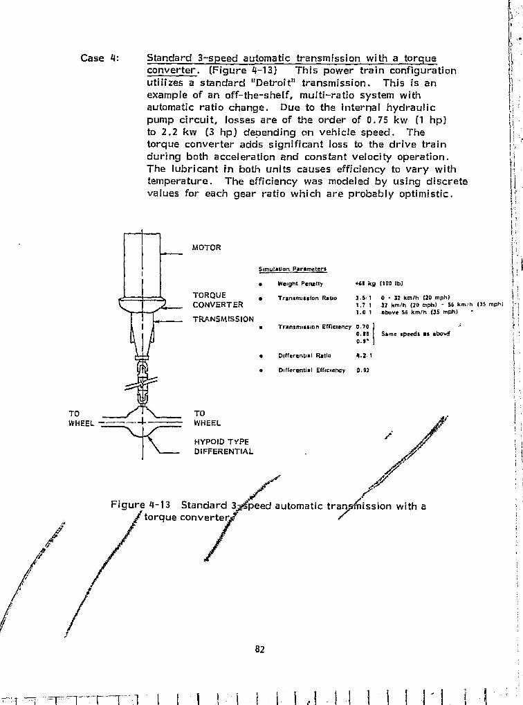
TOWHEEL
Figure 4-13 Standard 3torque converter,o
automatic tr
1.7 1 32 km/h (21) mph) - 56 km!h (35 mph]1.0 1 above 56 km/h (35 mph)
Transmission Efficiency 0.70
0.60 Same speeds as 4bo^
Differential Ratio 4.2 1
Differential Efficiency 0.22
III`
I
Case 4: Standard 3-speed automatic transmission with a torqueconverter. (Figure 4-13) This power train configuration
utilizes a standard "Detroit" transmission. This is an
example of an off-the-shelf, multi-ratio system with
automatic ratio change. Due to the internal hydraulic
pump circuit, losses are of the order of 0.75 kw 0 hp)
to 2.2 kw (3 hp) depending on vehicle speed. Thetorque converter adds significant loss to the drive train
during both acceleration and constant velocity operation.
The lubricant in both units causes efficiency to vary with
temperature. The efficiency was modeled by using discrete
values for each gear ratio which are probably optimistic.i . IA
MOTOR
Simulation Parameters
• Weight Penalty +63 k9 (1110 1b)
TORQUE • Transmission Ratio 3 , 5:1 0 • 32 km1h (20 Mph)CONVERTER
TRANSMISSION•
TOWHEEL
HYPOID TYPEDIFFERENTIAL
yS
82^4
l,l L !. Zi1_l ^_J_!-1-1-L_i^J I_'_!_I_L11J_,.
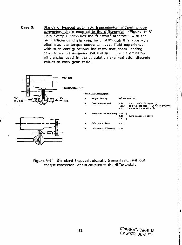
1values at each gear ratio.
TiW
Case 5: Standard 3-steed automatic transmission without torqueconverter, chain coupled to the differential. (Figure 4-14)This example combines the "Detroit" automatic with the {high efficiency chain coupling. Although this approacheliminates the torque converter loss, field experiencewith such configurations indicates that shock loadingcan reduce transmission reliability. The transmission j:.efficiencies used in the calculation are reali s tic discrete n
MOTOR
TRANSMISSION
Simulation Parameters
TO a Weight Peniilty +45 kg (100 1b)WHEEL.
e Transmission Patio 2.74 1 0 - 32 kmlh (20 mph)1.57 1 32 km/h (20 mph) 56 µ h {3SSph)1.0 1 above 56 km /h {35 mFil
a Transmission Efficiency 0.760.10 Some speeds as above0.22
• Dlfferentist Raba 5.0.1
e Differential Efficiencv 8.911
e
}
Figure 4-14 Standard 3-speed automatic transmission withouttorque converter, chain coupled to the differential.
^f3i
83 ORIGINAL PAGE ISOF POOR QUALITY
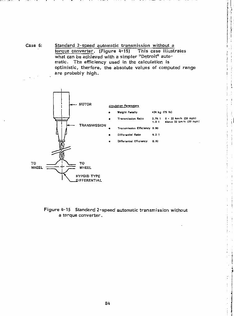
l
4.I
i
}
E
f
Case 6: Standard z-speed automatic transmission without atorque converter. (Figure 4-15) This case Illustrateswhat can be achieved with a simpler " Detroit" auto-matic. The efficiency used in the calculation isoptimistic, therfore, the absolute values of computed rangeare probably high. I ' i
MOTOR 5lmulaton Parameters
Weight Penalty +34 kg (75 1h)
q Transmission Ratio 2.74:1 0 - 32 km/h (20 mph) 'r110.1 abort 32 km!h (20 mph] i
TRANSMISSION• Transmission EU)clency 0.90
E
• 131ff_rontial Ratio 4.2.1 i
o Differentia! Efficiency 0.92
Figure 4- 15 Standard 2-speed automatic transmission withouta torque converter.
TO ` L_ TOWHEEL_^ WHEEL
HYPOID TYPEIFFERENTIAL
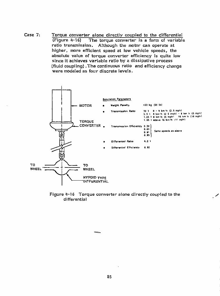
simulation Parameters
MOTOR • Walght Panalty +23 kg (SO Ib1
• Transmission Ratio 10- 1 0 - A km P h (2.5 mphl2.5 1 4 km 1 h (2,S mghi - t km h (S mph',1.25 1 9 kmih (S mph' 16 km'h (10 mphl
TORQUE 1.OS 1 nhove 16 km!h 4 tr mphl
CONVERTER • Tranamtsslon Efficiency 0.20
0.650.01
Same spaads as above
0.95
• DIffarantiai Ratio 4.2 1
• p(fterantiat Efficiency 0.92
I
Case 7: Torque converter alone directl y coup led to the differential(Figure 4--16) The torque converter is a form of variableratio transmission. Although the motor can operate atnigher, more efficient speed at low vehicle speeds, theabsolute value of torque converter efficiency is quite lowsince it achieves variable ratio by a dissipative process(fluid coupling) ,The continuous ratio and efficiency changewere modeled as four discrete levels.
1i
E
TO TOWHEEL * WHEEL
HYPOID TYPEFERENTIAL
Figure 4-16 Torque converter alone directly coupled to thedifferential
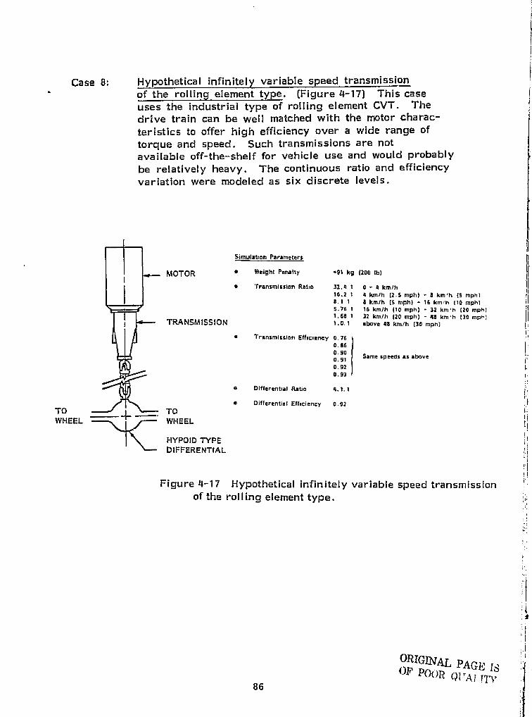
I
I
MOTOR
TRANSMISSION
TO TO
WHEEL ^^ WHEEL
HYPOID TYPE
DIFFERENTIAL
• Weight Penalty +91 k9 (200 Ib)
• Transmission Ratio 32 . 4. 1 0 - 4 kmlh56.2 1 4 km/h (2.5 mph) - 4 km ,h (5 mph) .8.1 S 6 km1h (5 mph) - 16 km # h (10 mph)5.76 1 16 km /h (10 mph) - 32 k1a'h ( 20 mph) j1,68 1 32 km /h (20 mph) - 40 km , h (30 mph) !I
above 48 km/h (30 mph)
• Transmission Efficiency 0.760.860.900.41
Same speWs as above
0.92 la0.93
o Differential Ratio 4.1.1 }. #
• Differential Efficiency 0.92
EI f
Simulation Parameters
1
}
Case 8: Hypothetical infinitely variable speed transmissionof the rolling element type. (Figure 4-17) This caseuses the industrial type of rolling element Cv i Thedrive train can be well matched with the motor charac-teristics to offer high efficiency over a wide range oftorque and speed. Such transmissions are notavailable off-the-shelf for vehicle use and would probablybe relatively heavy. The continuous ratio and efficiencyvariation were modeled as six discrete levels. }
Figure 4-17 Hypothetical infinitely variable speed transmissionof the rolling element type. I
I i
. j I
i
1 } I
.r
I' ORIGINk AL PAGE ISE OF p()( )R (J l rA t . r7 >F
86
r

0
Case 9: Variable _speed V--belt transmission. (Figure 4-18)The Electromatic Drive variable speed V-belt trans-mission has been designed for electrical actuation and.fence is compatible with the control system of an electricvehicle. As a variable ratio transmission it offers all thebenefits of motor/load matching. Efficiencies in the rangeof 86--94% are claimed and these would be relatively in-sensitive to temperature since the unit is "dry". Thedevice has been produced in limited quantity and so fieldreliability has not been documented. The transmission ratiowas modeled at five discrete values for the simulation.
simulation parameters
MOTOR a Weight Pmnaity +45 kg 1100 ib)
a Transmission Ratio 4.0: 1 0 - 16 km /h (10 mph)X1.0: 1 1ti km th (10 mph) - 32 km !h (20 mph)3.0.1 32 kmlh (20 mph) - 48 km'h (30 mph)2.0: 1 49 kmlh (30 mph( ^ 44 kmlh i40 mph]1.0:1 above 64 km1h (40 rr"ph)
CHAINa Transmission £fricioncy 0.90
o Differential Rstic 4.2. 1
TOa Dlfrerentiat Efficiency 0.99
TOWHEEL WHEEL
ORX INAl:, 2.>TEDIFFERENTIAL el'` FOUR s ir' Wx
Figure 4-18 Variable speed V-bolt transmission.
)1
II
°^ I
87j
1.
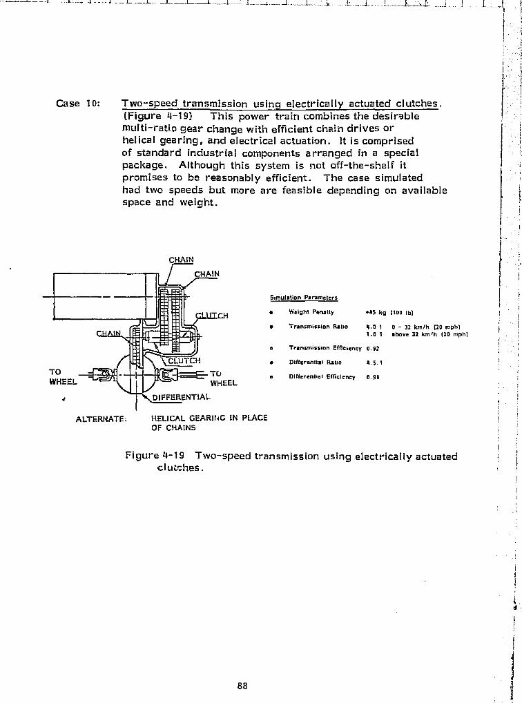
l
F
I. t
1
Case 10: Two-speed transmission using electrically actuated clutches.(Figure 4-19) This power train combines the desirablemulti-ratio gear change with efficient chain drives orhelical gearing, and electrical actuation. It is comprisedof standard industrial components arranged in a specialpackage. Although this system is not off-the-shelf itpromises to be reasonably efficient. The case simulatedhad two speeds but more are feasible depending on available Lspace and weight.
Simulation Parametersf
• Weight Ptinaity +45 k4 {100 16)
• Transmission Ratio 4.01 0 - 32 km1h 120 mph) {1.0:1 above 32 kmfh 120 mph) (I
• Transmission Efficiency 0.92
• Differential Ratio 4.5.1k i
• plffarentist Efficiency 0.98 tEL
HELICAL GEARING IN PLACE i 1
OF CHAINS
I ^ iFigure 4-19 Two-speed transmission using electrically actuated i
clu.;hes.
i
I
i
i
!q^ 1
f^
ALTERNATE:
88
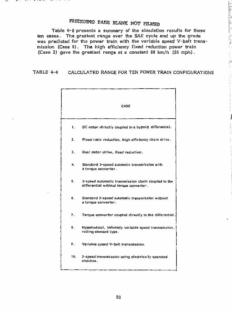
r ,
SIPREIDEDI G PArE JLAM NOT p LMED
Table 4-6 presents a summary of the simulation results for theseten cases. The greatest range over the SAE cycle and up the gradewas predicted for the power train with the variable speed V-belt trans-mission (Case 9). The high efficiency fixed reduction power train(Case 21 gave the greatest range at a constant 88 km/h (55 mph) .
TABLE 4-6 CALCULATED RANGE FOR TEN POWER TRAIN CONFIGURATIONS
96

i,
RANGE OVER SAE J227a/ORANGE UP 10% GRADE
WITH ENHANCED RANGE AT CONSTANT AT CONSTANTWITH REGENERATION REGENERATION 88 km/h (55 mph) 48 Ktwlh (30 mph)
km (mi) km (mi) km (ml) km (mil
48(30) 58(36) 76(47) 6.9 (4.3)
50(31) 66(41) 82(51) 7.4 (4.6)
51(32) 68(42) 82(51) 7.7 (4.81
40(25) 63(39) 71(44) 7.9 (4.9)
45(28) 68(42) 68(42) 6.4 R.C;
50(31) 64(40) 74(46) 6.8 (4.2)
48(30) 58(36) 77(48) 7.1 (4.4)
47(29) 56(35) 72(45) 8.4 (5.2)
53(33) 74(46) 72(451 9.2 (5.7)
52(32.5) 72(45) 79(49) 7.2 (4.5)
91

Range overSAE cycle
PeakBattery Current
Range at88 km/h
Range Up 10%grade, 48 km/h
Case km Case amps Case km Case 1«,
9 53-74 9 375 2,3 82 9 9.2
10 52-72 5 400 10 79 9 8.4
3 51-68 4 425 7 77 4 7.9
2 50-66 10 450 1 76 3 7.7
s ►
I ^
I `^
11
4.4.3 Recommended State-of-the-Art Power Train
Since the variation from greatest to shortest calculated rangeover the SAE cycle was only about 30 the selection of Case 9 asthe optimum state-of-the-art power train configuration needs furthersupport.
t ..{
In Table 4-7 those cases with the greatest range are tabulated as #well as the pezik battery current drawn during the SAE cycle, The two ivalues tabulated for range are with regenerative braking and enhanced ^ tregeneration respectively. (See Section 4.3.1) . The significance of thepeak current lies in the fact that the available energy from a lead-acidbattery decreases when large bursts of power are drawn. The Klecknerbattery model (Ref. 48) accounts for this effect and, although not includedin the present study, it is anticipated that greater range will result fromthose cases requiring lower peak currents.
TABLE 4.7 RANKING OF CALCULATED PERFORMANCE Ej '
1155'
I
i
;^ f
r
The variable speed V-belt transmission with the DC series motorE,, t
forms the basis for a state-of--the-art power train which offers-0
High calculated range
I
o Good efficiency,
4
f
92 ^,
.Y
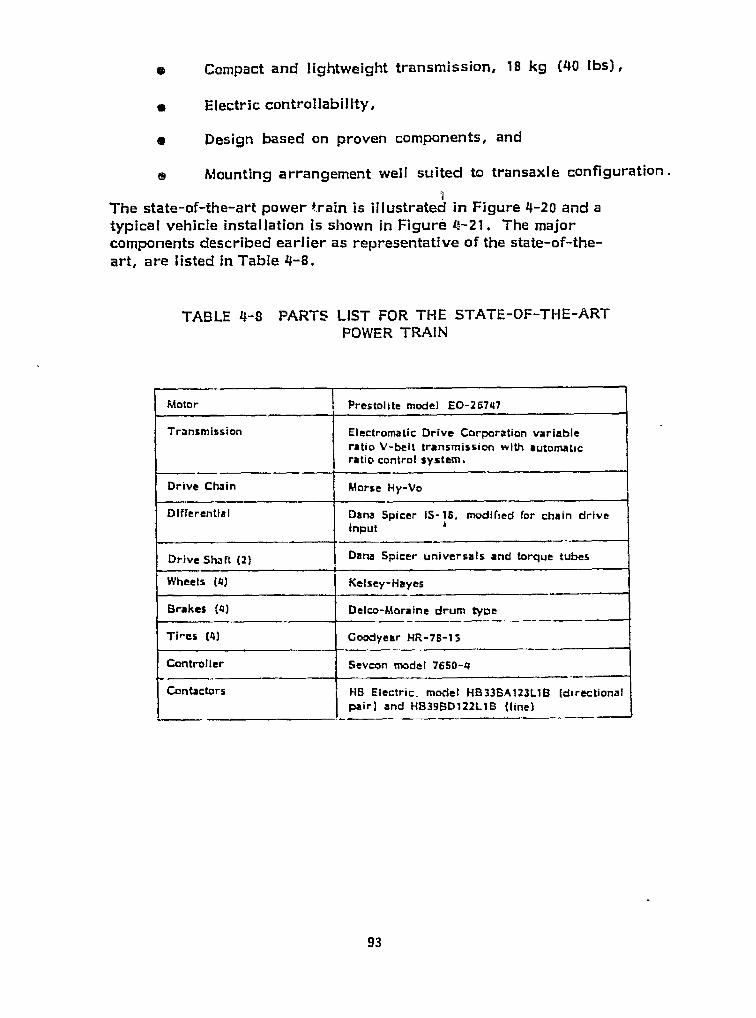
I ,^
r JJJ
Compact and lightweight transmission, 18 kg (40 lbs) ,
s Electric controllability,
s Design based on proven components, and
f ® Mounting arrangement well suited to transaxle configuration.
The state-of-the-art power train is illustrated in Figure 4-20 a,1d aj typical vehicle installation is shown in Figure 4-21. The major
j' components described earlier as representative of the state-of-the-? f art, are listed in Table 4-8.
TABLE 4-8 PARTS LIST FOR THE STATE-OF-THE-ARTPOWER TRAIN
t
E
t
i{t
'' 1
i
l1
i
is
I`
Motor Prestoiite model EQ-26717
Transmission Electromatic Drive Corporation variableratio V-belt transmission with automaticratio control system.
Drive Chain Morse Hy-Vo
Differential Dana Spicer IS-18, modified for chain driveInput
Drive Shaft (2) Dana Spicer universals and torque tubes
Wheels (4) Kelsey-Hayes
Brakes (4) Delco-Moraine drum tyoe
Goodyear 14R-78-13Ti res (4)
Controller Seveon model 7650-4
Contactors I H13 Electric, model HB33BAl23LIS (directionalpair) and HB39BD122L I S (line)
t
F.
1
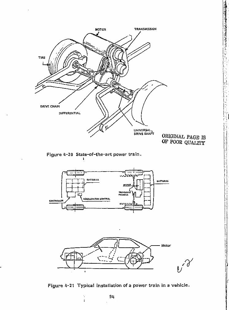
JOt MAT. 'DAnOld' POOR QUALITY
ROTOR TRANISMISSLON
Figure 4-20 State-of-the-art power train.I
"TMIES
PADLACE
Motor
4

L i
F
rt =
4. 6, 4 Predicted Range of the State-cf the-Art poorer traing
Th ta . I tai ht of the state-af-thewart power train Is estimated toe } ` x.a gbe 295 kg (650 IN . Since this configuration was analysed in the previoussection (Case 9) at a Freight of 365 kg (950 lb) , the sensitivity valuesof Figure 4-8 can be used to approxi.mately scale the predicted mange for
the lower Weight case,I'
I;
Table 4-9 summarixes the predicted range for a vehicle with thestate-of-,the-art power train. The total vehicle Freight is 1587 ko (3500 Ib) .Absolute values for range are quite sensitive to component modelling andcontrol strategy. The control assumption here is that the power trainInstantaneously provides needed tractive effort and that all braking isregenerative. The results given here (Chapter 4.O4) are self-consistentand primarily intended for relative comparison. In Section 5.3.2 thestate-of--thy:-art pager train is subject to another analysis based on adifferent set of component models and with a constant current control scheme.The range predicted there is only 50 km (31.2 ml) over the SAE cycle.In general, caution should be taken to review the conditions and assumptionsunderlying absolute range predictions when diverse sources are compared.
TABLE 4-9 VEHICLE RANGE WITH STATE-®F-THE-ART POWER TRAIN
CYCLE RANGE, km (ml)
.SAE J227 a/1] so (36) -- S0 (SW
88 km/h (55 mph) 76 (47)
10% grade, 48 km/h (30 mbh) 10 (6.2)
* With .regeneration -- With enhanced regeneration.
t
95
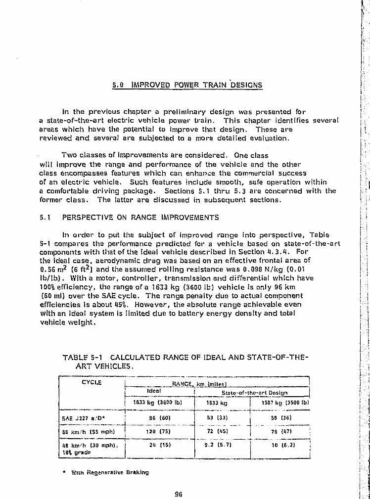
S, 0 IMPROVED POWER TRAIN DESIGNS
In the previous chapter a preliminary design was presented fora state-of-the-art electric vehicle power train. This chapter identifies severalareas which have the potential to improve that design, These arereviewed and several are subjected to a more detailed evaluation.
Two classes of Improvements are considered. One classwill improve the range acid performance of the vehicle and the otherclass encompasses features which can enhance the commercial successof an electric vehicle. Such features include smooth, safe operation withina comfortable driving package. Sections 5.1 thru 5.3 are concerned with theformer class. The latter are discussed in subsequent sections.
5.1 PE=RSPECTIVE ON RANGE IMPROVEMENTS
In order to put the subject of improved ranee Into perspective, Table5-1 compares the performance predicted for a vehicle based on state-of--the-artcomponents with that of the ideal vehicle described in Section 4.3.4. Forthe ideal case, aerodynamic drag was based on an effective frontal area of0.56 m2 (6 ftz ) and the assumed rolling resistance was 0.038 N/kg (0.01Ib/ita) . With a motor, controller, transmission ¢rid differential which have100% efficiency, the ranee of a 1633 kg (3600 lb) vehicle is only 96 km(60 ml) over the SAE cycle. The range penalty due to actual componentefficiencies is about 45%. However, the absolute range achievable evenwith an Ideal system is Iimited due to battery energy density and totalvehicle weight.
TABLE 5-1 CALCULATED RANGE OF IDIEAL AND STATE-OF--THE-ART VEHICLES.
CYCLE RANG km milesIdeal 5tnte -of-the-Art Design
1633 kg (3600 Ib) 1633 kg 1587 kg (3500 Ib)
SAE ,1227 a'D" 96 (60) 53 t33) 56 (36)
88 km`h (55 mph) t 120 (75) 72 (45) _I
9.2 (5, 7)
76-(47)I '
10 (6.2)118 km^h t30 mph). 24 (15)
10% grade_ ---- — - ---. €
With Regenerative Braking
96
In addition to the energy requited to accelerate the vehicle,losses are clue to:
a Aerodynamic draga Tire roiling resistance
Transmission/gearing lossesMotor/controller losses
For each of the three driving schedules the major Iosses tend tooccur In different parts of the system. For the state-of-the-artdesign, presented In Chapter 4.0, these can be ranked in "majorloss first order.".
a Over the SAE cycle the major losses are due to:
Motor/controllerTires
- Aerodynamics
During the 88 km/h (55 mph) crulse the major- losses aredue to:
wAerodynamicsTires
When climbing a 10% grade at 48 km/h (30 mph) the majorlosses are due to:
wMotor/controllerTiresTransmisssionlgearing
Although aerodynamic drag is a significant factor at higherspeeds, the effective frontal area (area x drag coefficient) of 0.56 rnz(6 ftZ ) represents a value typical of the most streamlined bodyshapes. As such It will be difficult to affect aerodynamic im--provemants. Motor/controller, transmission and tire efficiencygains are, however. achievable and will result in increasedvehicle range.
5.2 NEAR TERM TECHNICAL~ IMPROVEMENTS
In the course of reviewing electric vehicle technology anddeveloping a preliminary state-of-the-art design, several potentialImprovements were identified. The following paragraphs describethose near--term technical advances which could Increase vehicle range,
97
m- !!

i;
s The separately excited * DC motor with the ElectromaticCVT represents a combination of two recent trends,.There has been significant interest in the separatelyexcited motor, which appeared as a trend In the state--of-the-art assessment. The separation of field and armaturecontrols should offer advantages In reducing controllercomplexity..since the law current field circuit can be usedto implement vehicle reverse speed and to control regenerativebraking. The Electromatic CVT is a derivative of a reliablesnowmobile transmission and has been built into the MechanicsIllustrated " URBA R car (Ref. 55) . By combining aseparately excited shunt wound motor with this V-belt type oftransmission, a more efficient and driveable power train mayresult.
Since decreasing weight directly improves vehicle per-formance, light weight power train components aredesirable. Candidate materials include plastics, composites,and other high strength to weight ratio materials.
a Several manufacturers have noted that It is feasible toachieve lower rolling resistance in a tire designedespeciall for electric vehicles. Parameters to beoptimized include:
- Aspect ratio- Sizing- inflation pressure- Cord angle- Compound selection- Tread contour- Rim width
0 A greater range can be achievad for a vehicle with a greaterratio of battery _mass to overall vehicle mass. This ratioG referred to as the "battery mass fraction."
e Since the size of most electrical components Isproportional to current, higher volta ge batteries shouldresult in a smaller system which is lighter and morecompact.
* In this report "separately excited" refers to a shunt wound motorwith separate armature and field controls.
913t.
k ^P
}
Several studies (i.e., Ref, 63, 64 and 65 )indicate that an AC motor and controller package willoffer weight and cost benefits over the DC systems.The weight reduction atone can increase vehicle rangeif efficiency is not sacrificed.
a A trade-off analysis should be performed to ascertain thepotential for using a dual set of batteries, One set wouldbe capable of fast charge and discharge to providepower for acceleration and to accept regenerated power.The other set would be suited for steady charge anddischarge and would 'Be relied upon during cruiseoperation. This approach was attempted with the GEDelta vehicle (Ref. 21 ) and in . some recent Japanesevehicles.
to Battery development has been recognized as a key tothe success of the electric vehicle program. Efforts to 1improve the energy storage capacity should be encouraged.
® Mechanical storage of energy in high density, compositeflywheel structures can provide effective battery loadlevelling. Power needed in surges for acceleration orgenerated during deceleration can be transferred from,or to, the flywheel.
In order to evaluate any of these potential improvements, more detailedstudy Is required. Due to limited Funds and time on the present contract,only the most "Important" area (s) could be analyzed. Therefore aset of preliminary evaluation criteria were established to rank theimprovements by priority. Improvements were sought which;
0 Represent near-term state -of-the-art rather than advancedtechnology,
0 Offer some potential for range improvement which has not beenfully evaluated (For example, since tire improvements havealready been shown to increase range, there Is little to addto our understanding in this area short of a prototype electricvehicle tire development program) ,
0 Present minimal risk to the immed iate objectives of the electricvehicle program.
e Are technically feasible, and
Represent a reasonable level of evaluation effort.
99
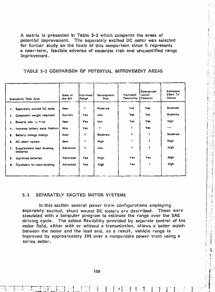
l2
A matrix Is presented in Table 5-2 which compares the areas ofpotential Improvement. The separately excited DC motor was selectedfor further study on the basis of this comparison since it representsa near-term, feasible advance of moderate risk and unquantified rangeImprovement.
TABLE 5-2 COMPARISON OF POTENTIAL„ IMPROVEMENT AREAS
evaluktlon Trail. AreaState -0t .
the -Artimprovedr:Anga
0ave10ls hMF11
Rt%kToc hnicA lF®anibllity
Comhaa^FCill-izationPotential
I:1St"satedI: tlort ToAlters
1. Sapanataly cl,ened DC motor Near f A4odarate Yes yes lttodarmle
:. CollWoInnt weight reduction Currant Yes Law Yet Yes 16Wtc4to
Electric vah `^a t1,2s Near Yak Lon yet Yet Nigh
3", tncrv4sa Wtary "1411 rractiatl Now %I*$ t 1 Yes ^--
S. tlattsry kultagc 04nge Noar t l4 D&rate r Aiatkrate
S. AC =Wr system Nair T trlgh t High
7. Supplan-Atual load leveling Advanced t Low T t Nigh
tAttiolat
R. Itnprovad batteries Advoond Yes trigh Yes Yes ttlgh
4, F'lywttatels for load • lev-aling Advanced Vas Mlgh yes 3 Nigh
f
j
h
t'
t
i
]
j
I
It
5.3 SEPARATELY EXCITED MOTOR SYSTEMS
In this section several power train configurations employing 1
separately excited. shul7t Wound DC niators are described, These weresimulated with a computer program to estimate the ranee over the SAE ^' Fdriving cycle, The added flexibility provided by separate control of the Imotor field, either with or without a transmission, allows a better matchbetween the motor and the load and, as a result, vehicle range isImproved by approximately 20% over a comparable power train using saseries motor. t
k
i
100
F . ,1
e
^l
i
^f
I
1
5.3.1 computer Simulation Model
An Iterative simulation with empirically adjusted componentmodels was used to investigate the performance of the separatelyexcited rotor systems. This computer program is proprietary toTRIAD Services, Inc, of Dearborn. Michigan, The state-of-tire-artpower train design using the series DC motor (Case 9 of chapter4.0) was also simulated with this program to provide a directcomparison between the series and separately excited, shunt woundmotor systems with the same analytical tool.
The computer program simulates a given vehicle, drive trainand control strategy using an Iterative process based on currentfeedback. The accelerator pedal position controls motor current.Since the most efficient manner of extracting a given amount of energyfrom a battery Is to do so at constant current, motor current is heldconstant during the accelerating portion of the cycle. The sequenceof program execution is, generally, as follows:
The speed range (i .e. , 0 - 72 I(m.' h for the SAE cycle)Is divided into 1 % velocity steps;
A first "guess" is made for motor current and the =tot-torque is calculated;
By looking "ahead" 111 2 of a velocity step an averageroad load Is computed from the vehicle model and the motorspeed is calculated from the drive train ratio;
p The motor torque is reflected through the power train anda net vehicle acceleration is obtained (acceleration(tractive effort - road load) _ vehicle mass);
0 From the acceleration, the time to reach the end of the
velocity step can be calculated;
At each step vehicle speed and drive ratio is usedto compute motor speed and, since current is known ,the motor voltage is calculated from the motor model;
1If an armature chopper is employed, the duty cycle Is Icalculated from the ratio of motor voltage and batteryvoltage (at the battery current) .
The battery discharge characteristics, and the time atdischarge, are used to compete the percentage energy drawn;
101
- ^ .art = • -•- _ ^c s.J _..,w, _ .1.. ;.^. .,.. ^.i . 'a . . .1.a• -. •.^a .se-.L w...,.^^
k .w
I 4
F:I'
4
j
$
The process Is Continued until the "Cruise" speed YM km,^h(45 mph) is r oactied;
The time to reach the cruise speed is compared to thcespecification (2S sera, the motor mn-rent is than :adjusted.up or doxvn, and the prwess is Kerated until the time toreach cruise is as required..
Rar rrge at constant speed is calculated by working fromtl,,, road load "backwards", throu h tine drive tram, to theba' ttery3 .
For each of the power trains witli si Fpai ,ateiy excited='%tors.and for the set-it's rrvtor design (Case 9). several Simulation runsware made to select the hest final drive ratio. Common paramoters forthese studies were:
Q1 Vehicle test weight was 1633 hg (3500 Ites.)
The vehicle dynamic Windt l Included;An effective frontal area of 0.56 m"- (6 ft") .
b A time radius of 0.3: m (12.6 in.)A rolling resistance of M IR, N; kg (0.01 lie.: 1h.)
The effiicionc: , cif they armature choppor controller wasassumed to be 96%.A motor mathematical model was dueloped from theP"eStOlitL 110-:6.'47 data (shomm earlior In Figure 4-9).and included:
Armature resistance ^ 0.01 ahms.Maximum tot-clue constant 0.:942 ft. lb . per :imp,Minimum WrgUa constant = 0.09; ft, 'Ib. per• amp.Field strength variation 3: i .
The Elec.tromatic CVT was shifted over a ranee from3.41 . 1.0 to 0.68 : LO, Its assumed officizney. A isShown in Piqure 5- 1.
4 For • regenerative bral:ing the current vas limited tee 150 amps.
Based e':n 4 sts pe*rformod with the CDA town car. thereeooncration efficiency used vvas 83$. Due to the currentlimit. some kinetic energy was dissipated in they frictionbrakes to achieve the braking requireimsnt of the SAECycle
s
E
i
F'i
j.
4

w
!Ma
WinvWSStim R114
Pigure S- ] Electrmatic CVT e#tivien ^
S. III atxO C alc-ctlaticns
The .^Nmer trains StuSiO,)* in this *ection are distinguished byarnmturij .. Ontvol, field contr'M or the incorp.,oration of the ^3a^trc^r:,aticOAT, F'i)trr case etatpt^ %ring shunt mound were cowOdered.
Fl^ure^ F,- 1s a blo4l\ didgrarn i^Nt the l ow er train with the serlasmotor and ^ Vl h tease ga , The NitterN , current and motiir sperm for thiscase is slump in Figure S - a. A possible ci itrol scenark, begins withthe transmission ratio- ,.1t S,#t, t when the vehlcic, is at rest. Armateuv.Owppinq is used 4,N accelerate the vehicle until the duty cycle re4ehaslt't (motar v"Altage ^, t.Attery viMtag0 and further aQcelarati pn. aboveaNNut I£ l nr. ` kt t t mph) a Is acnxm llshed by a ►; hiftin,, the transm siloAt a wnjtatit m.-%ti.Nr s e ^i, Slavice the road load !s appriooimativky camstarrtduring this prt ckf the drivinci cycle. (see Figure. 4-71 ) the battery current!s ccrn4t, trt. Sinese the is no lcrrr,)car acceleratin r there is a r*e.itacedl:Nid don, ,ind for cruisinj at ^"k% km.'h (0 mph), tho transnrission !s daa n-L%hitj k^^ the tnoUrr $.Pea j lncre ses o a ut,- see= spe;;r ! united w w n Rrmand tho current. dropw s0stanW%11y. With the mkOr at this spev-d thetransmission. ratio is t,SS: 1. Further do reases, in ciemanded tcrique
(^"-,Vvr-Atov QvntmAled, throuilh V.edM NsltkinX are aQ.i r!i rtmadatW toeh;^ppin^j the armaturo \-iMtaqe, Rmdii ally, the ,^\mVir! logic responds t^^accweler*aVv pea, it (utriquO demand t--e a hlerarchy° of armature. etuipping; rrd tr;Ansmissksn contrO with the mAor Speed defining an additionaldts6sion ptht if motior speed is at its seal, WIN RPNO lmreased tarquedemmild is met t^y, UP'Shlftin and dNr,,-ase.o hxtd- is achieved by ch;^ppinqh% the wmaturt Orzult,
103
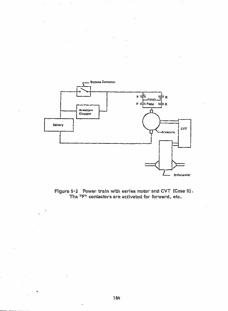
104
A.
Figure 5-2 Power train with series motor and GVT (Case 9).The "F" contactors are activated for forward, etc,
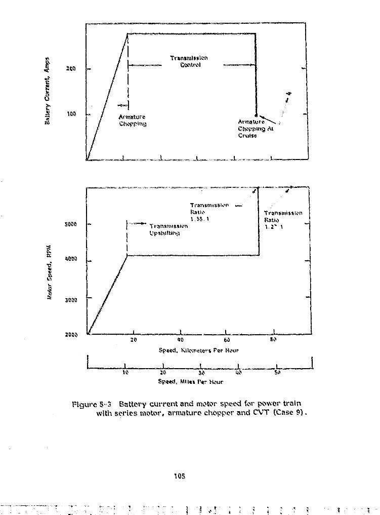
iao
'1'rxns^tisixxleri4 ^aa^tr^t
Ara^^tu^^eAr Mur
c hoppmcrulso
4
i
:. I
„^ 3
°i
inn
SON
C6rx ON
IUlU
^° 3t111ti
NOa^ +tQ 6^ t4A
10 2z 3^ ^` SO'
Speed, Ml its fear Hk^ur
Figure S- S Sattery current and spee4^i for poNver train
with series nutter. are iture chopper and CVT (Case 9) .
^r
!
I;
ri
• - t -. ^.5 der-R _. ,. _ -
^^ ^'
ii
1
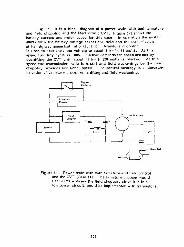
entiat
#i
4
,F
I
Figure 5-4 is a block diagram of a power train with both armatureand field chopping and the Electromatic CVT. Figue 5-5 shows ther battery current and motor speed for this case. In operation the Systemstarts with the battery voltage across the field and the transmissionat its highest numerical ratio (3.41: 1) . Armature choppingis used to accelerate the vehicle to about 8 km.' h (5 mph) . At thisspeed ti-ie duty cycle is 100". Further demands for speed are met byupshifting the CVT until about 45 km 'h (28 mph) is reached. At thisspeed the transmission ratio is 0. 68: 1 and field weakening, by the field
{ chopper, provides additional speed. The control strategy is a hierarchyin order of-armature chopping, shifting and field weakening.
-{ r^:E
A4' 4
1
_
Ii{
is 1
1 ^a
ti"i
Figure 5-4 Power train with both armature and field controland the CVT (Case 11) . The armature chopper woulduse SCR's whereas the field chopper, since it is In alow power circuit, could be implemented with transistors.
106

200
wb.
Ian
I
J--. Tr^n^i ►► ir^ttEoo ►I{control
Armattive
Chopping
F^Eske!
C onvol
3000
r 2000
1000
IO
40 6q rj0
speed. !:lIonlattl s Pot, hour
10 I0 30 40 5a
speed. R4lles Por Ilour
Figure 5-5 Battery current and nvotor spood for power train withsepar-lite(y mAtod motor. ormature anti field c11iippor° and CVT(cask) 11) .
107
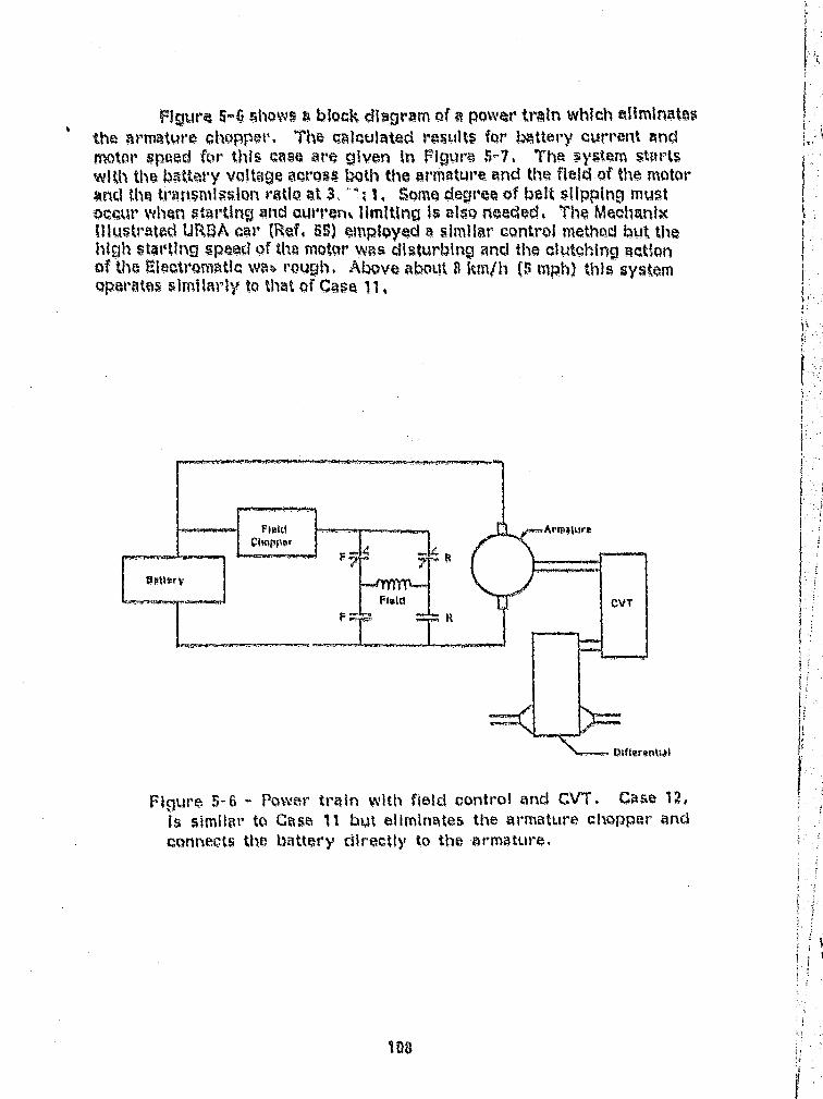
4s'
is j ^
FlULlre 5-6 Allows a Wock diagram of a powar train which eliminatesthe armature chopper- The calculated results for bAttery current rindrnrrter speed for this case are given In Figure 5-7, Tha system Marlswith the iaattar°y voltage across i tip the armature and the field of the motorwrati tinetl ansm l ^sion ratio t ,. `, 1, Some degreea of i}ei 51i trr mustoccur `Yh4n starting and Curren% limiting is also needed. The MeolianixIllustrated URBA nar k (fief. 65) employed a Mmllar control mothad but the111011 st41 ,0110 speed of %ha motor wits disturbing and the clutching actionof the MectromAtic way rough. A ve 840L)t 8 kni/h (S tnph) this systemoparates s1milfir ily to that of Case 11,
ntpat
Figure 5-6 - Power train with field control and CVT. Case 1w,is similar to Cass: 11 but eliminates the armature chopper andconnects the battery directly to the armature.
108
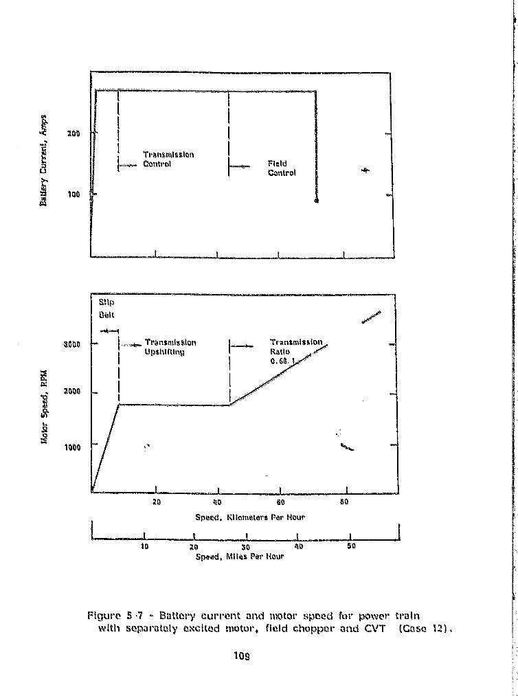
'fr^ngttrk^slgtl I
r control Fuld
Control
200
t
100
a
ri
i
tilp
l3alt
tlprltikfting
IL l
,3040
9^aoo
pengq471VY
^I
l
Transmission
Mai oa.6a, !
.3
xlog
t---._.r
.4,
20 40 60 so
Spew. Kilan star: Nr hquri` t t
t0 ^0 SO ^0 50,
spaad. Mile% Peal- Hour
{ Figure 5 , 7 a Satte,ry ul • r •erit and motor speed for Power 0-0111with separately excited nitAor, field chopper and CVT (C n se 121 ) ^
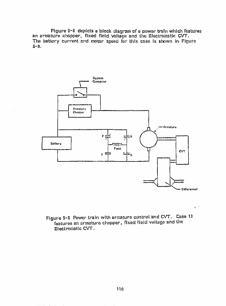
k
3
Z
9
Figure S-8 depicts a block dingi•am of a poww- train which featuresan armature chopper. fixed field voltage and tine Electronittic CVT,The battery currant and mater spied for this case Is shown In Figure5-9.
r^YNa^s
}' II
ArmatureCfrnpper ^ 1
i' Amalury4 -^ ^ F f r.: ^.
;,,^ atatterp , ,
l it CVT
a
[lirtpr^nlial 1.
s
l=igur •e 5^8 Dower train with armature control and CVT. Case 13features an armkItut •o chopper, fired field voltage and theEl ectromatic CVT .
110 ^^
- ^^^.:a^.k.^-^'^___^._^.-t .: ^_x-^'d.- . ^ ^:s'r.11 -^.a.f^=+X., 3; a_..s_ ..-4. c_ ......Y_ _ _._ _::I .._ -. k - ., ., -..^ _ _.__^ .......- ^slj. •«[w^.
^ ^pn
4J
EA
i p'p
C
Control
ArmatureChop wing
f;
300
TransmissionUpshitting
^qOp
ZOpp
zn ^n so ^p
Spew. Ktlo mttrs E`er Hour
TO 20 30 40 gp ^.
Spepd, Milita Por Itaur
fiiqurr 5-9 - matter), c UNT.-nt and MAW speed for F mvr trainWRIJ sePRI' ly eXCIted MatOl'. nr ►rtatr<Ire etxippvt- and CV T' (Gast, 13) .
ill
14
i r
z
4 ^
3 ^
7p ^

---it I c
1 3
f
In this configuration the motor has a linear torque-speed characteristicsimilar to a permanent magnet field motor. Reverse can be implementedby switching the low current field circuit. The control hierarchy consistsof armature chopping to about 18 km/h (11 mph) and transmission controlat higher speeds.
Figure 5-10 is a block diagram of a power train which performsall control electrically and features a fixed gear reduction. The batterycurrent and motor speed for this case is given in Figure 5-11. For thisHall electric" power train the maximum field voltage and armature chop-Ing is employed until the battery voltage is impressed on the armature.Further control range is achieved by field weakening. I
Fl v«
Figure 5-10 -- Power train with all electric control. Case 14, issimilar to Case 11, but eliminates the CVT and does all controlelectrically.
112

cL E
NCL
w
u
Z^
PO
IN
100
ArmatureChopping
Field
Central
5000
AND
Iu3
a3000
1000Z0 40 60 a0
Speed, Milometers Per Hour
10 20 30 40 50
Speed, Miles Per !ia}ir
Figure 5-11 - Battery current Find motar r>peed for power trainwr ith separately excited motor, arm iture and field choppers andfixed gear reduction (Case 14)
113
TA
' Y
1
1i
1
The results of ranee calculations for these five cases ave summarizedIn Table 5-3 for the SAE J227 a;D driving schodule. Thtos primary cbjectivoof this comparlson was to identify relative improvements III range over thiLsSAE eyela
TABLE 5,-3 . COMPARISON OF CALCULATED RANGE OVER THE SA CYCLE FOR' SEPARATELY PENCI"{TED AND SERIES MOTOR SYSTEMS,
Strict, ^ Shunt ►►mound, Sio aratAaty oNcibad
Chop Chop Fixed Chop Clwp
Chop Chop h" ad CtmpI
EM CV`V EM CVT W CVT EM,:CV'T
++15 kni 5i hw 54 fire+ Sb kilt S$ km130 rm} (34 nu) t9S 5 mi} (34,5 pri} i3ti-1 a,A1
4000 RPM 3141 I;r'^1 3491 RPM ^ U1 9.4 RPM ? 'W10 RPMi
CASE
Motor Type
Rrrtfatur tl Contrnl
Plaid Control
fi ratwlliallam 'Typo
Differential Ratio
1633 kit M600 lb 1 vehwt.
Motor spood at 86 kits If{55 tnplf}
There i5 a difftrrenee, it1 the c:alcultaied range for the series motordesign shown hertz and that presented as Cease 9 In Chat tr^r +l. p . This
k is prlmtarilV titre result of assumod efficlencies and transmission shiftingt. range as folli-mm
Tht- shifting range of the Eloetromratic used here isnarrowor (3.41 to 0.66 Ls 4.8 to 1.01 and the Over-all drive ratio Is lower (2-9. 1 vs 4, 2, 1) .
6 A lever transmission rifficlency was assumed hore(see Pipure a-1), particularly at higher ratios.
t f
{
0
Regenerative braking was limited to 154 rimper es.Less clnergy, therefo re, was rmoverad during
ida^.eltaration. ^` 1
r
°oFor the state povYo:• train which ^^+elr^hs 29" I.r^ (t;54 il^s^scaling the present results predicts a range of 50 km (31.2 ml) overthe SAE cycle. The r •osults shown In Table S-3 are consistent sinco
e
t
`f
i^}
115
4r
c a , y,
they are Leased on the same component raaadels and computer analysis,and Illustrate that the use of a separtatt1y exc lteci, shunt wound motoroffers a definite benefit in ranele over the SAE cycle. This isreasonable can physical grounds as discussed below.
Consider can electric vehicle which must operate bath over thflSAE cycle and at a steady top speed of, for example, SS km°h (55 mph)For a Power train consisting of a fixed ratio reducer and a series woundmotor, the top speed of the vehicle will correspond tie the maximurtaMotor speed and, with armature voltage control, will be reached at fullbattery voltage. This trap speed establishes the overcall drive ratio.Since the efficiency of a series motor Is naaximum in tho recal4an of highspeed and high voltage, the power train Is ►velI matched to tho load forSteady high speed operation, However, in order to delbs er the powerpeaks of the accelerating portion of a stop-rand-gcs driving cycle, themotor must be controlled to opvrtatea at reduced armature voltage andspeed for a significant part of Its duty cycle, This Is a region of lowermotor efficiency. Thus, the rt^guireme•nt to reach a top speed setsparameters in the series motor power train which tare In conflict ►withachieving optimum r •trnne aver- the SAE cycle, tine ctannot, fear ex mule,match the motor efficiency to they pock power drmanded during tacceltaration.
The separately excited, -shunt wound nwtor and control system,provide the flexibility to match motor characteristics to the diverserequirements of both trap speed and stop-rand- qo operation. Typicallya shunt wound motor achieves maximum efficlency tat "Wst speed" whenfull armature and field v-oltage are applied. The controilot- can be designedto deliver the power peaks while the nxitor is at its maximum efficiency. Thisraaore effectively (although perhaps not optimaily) matchos the load and resultsIn improved range over the SAE cycle, Top slat>ed operation Is tachitavx ed byweakening the field, which decreases the generated voltage (back EIIF) andallows higher motor speeds.
The advantage of the separately excited, shunt wound iaaMor systemover the series 9vound motor Is the result of the nxitor; controller systemflexibility, and not Inherent to the machines alone,
In addition to absoluta , preo- tions of range s:ewrtal qucalittative factors merit considtw ation in an elex-tric vt,)hic Ir., traindesign. Key= among those are reliability, nuflntainobility and dkwvlopFanent risk.
The absence of can armature choir pt. r in C:aso 12 rmjuire:: thatthe V--belt slip In ordor to start tht^ vehicle trom rest, Ibac.essivewear and pacer driveabil lty can he expected from the Lloctromati.:transmission under these conditions. This case is thorefore,rejected for the electrlc vehicle application.
116
t rIN
The tradeoff considerations between Cases 11,13 and 14 aremore subtle. All of the range predictions shown In Table 5-3 were }made assuming a 1633 kg (3600 lb) vehicle which implies a power {train weight of 340 k9 (75.0 . lb) . Since the CVT weighs about 18 kg €(40 lb) and the field chopper about 2. 3 kg ( 5 lb) , the Case 14 powertrain will weigh 279 kg [615 lb) . This should result In a rangeg f
over e SAE cycle of 61 km (38 mi) . Moreover, one can expectgreater reliability and lower maintenance casts to be associated withthis "all electric" drive. However, the high motor speed presents
offsettingti consideration. Traction motors are not normal! built ,
^ i f an fifset ng n y ^ ^for operation touch above-4000 RPM. Special designs are availablewhich incorporate high strength armature construction and high
f speed bearings, but these tend to be more costly and field experienceis limited. A low speed motor for Case 14 Is feasible but it will,
`f necessarily, be larger and heavier. Cases 11 and 13 are attractivedue to the lower motor speed; however, there still remains somedevelopment risk associated with refining the Electromatic CVT.
Separately excited motors can provide a range advantage overcomparable power trains with series machines. The motors areavailable, at least by special order. These systems require tailored 'controller designs which are within the near term state-of-the-art.In view of a rapidly advancing electronics technology, the all electricsystem with a high speed motor (Case 14) is the most viable designapproach. Development of the Electromatic transmission should continue ?and as positive experience is obtained, the power train with fixedfield voltage (Case 13) may be a good alternate.
i.
The continued development of high speed DC shunt motors andelectronic control packages will enhance the potential success of the Eall electric" drive concept. In this context, the dual motor drive (Case 1
3 of Chapter 4.0) with separately excited machines and a single controllerwarrants some reconsideration. In addition to these power train developments,further research is needed to provide better batteries, expanded use of !'lightweight materials and low rolling resistance tires, since these have isthe major potential for improving range. [
5.4 MISCELLANEOUS IMPROVEMENTS
Several other improvements will lead to features which shouldienhance the commercial success of the electric vehicle. These maynot increase range but are desirable in order to satisfy the generalexpectations of the potential electric vehicle buyer. The following iparagraphs describe these miscellaneous Improvements: ? :.'_
i
Smooth stopping of an electric vehicle utilizingalectrical dynamic or reganerative brakes In con-junction with hydraulic brakes requires a brakeblending control system. Consistent with safety,such a system would blend the electrical and hydraulicbraakes In response to driver input.
The reliability of electric vehicle power train componentsshould bo carefully assessed. Areas of weakness shouldba identified and Improved.
,r
The Issue of safety needs to be carefully addressed toensure compliance with applicable standards. Currentdesigns, that have primarily been vehicle conversions,generally meet applicable ROT and SAIw vehicle require-ments. Other vehicies, especially those that are basedon golf cart and similar technology=, are not viewed asfavorably. Compliances with the National Electrical Codemay also be a requirement.
In ardor to achieve the maximum weight and volumetriceconomy for the vehicle package, the m ator and trans-mission (or gear reduction) should b£ designed as asingle mechanical unit.
e The state-of-the-art assessment presented In Chapter 3,0Indicated the need for off-the-shelf, Lfficient and reliableautomatic transmissions for electric vehicle use. TheEle.ctrona-tic CVT, when used in conjunction with avariable speed electric drive (as in Ctsse 9) promisesto fulfill this need, Efforts to refine the develop-ment and prove the field reliability of this type of unitshould be pursued.
Another system used on off-the-shelf electromagnetic clutches,%used in Case Soy of Chapter 3.0) also shoes promise as anefficient and reliable automatic transmission. A Preliminarydescription of this latter concept is presented in the neat section.
a.5 DISCRETE GEAR CHANCE AUTOMATIC TRANSMISSION
A two speed, discrete dear ci-wngez automatic transmission,used on rormsprarq dry electromagnetic clutches, is shown In Figure5-12. The disc clutches couple alternate gear trains to the drive mtor.Low gear is 4-.1 and hiqh Is 1.43:1. The transmission rutput clear iscoupled to a standard DAna differential with a modified Musing througha rind gear of 4.5:1 ratio. The differential outputs are coupled throughtwo univet•sa3l shafts typical of the Corvette and VW transaxle approach.
117

': 1..Figure 5-I2 Layout of a two-speed electromagnetic transmission.
Traction
118
119
^^F
1
1.
I j
a e. i. 2 1 i __ .l /s"x
Power flown in the two gears is shown in Figure 5-13 and a typicalvehicle mounting is shown in Figure 5,14.
}
;w
Some of the features of the electromagnetically shifted, discretegear change, automatic transmission are listed here.
a The design is based on off--the-shelf Hirdware.Formsprag electromagnetic clutches are shown.
® The unit is compact and is estimated to weighless than 100 pounds.
Low electrical power is required to activate ormaintain the clutches. Only 31 watts (.04 hp) is requiredas compared to 0.75 - 2.2 kw (1-3 hp) loss of conven-tional hydraulically actuated automatics.
Low drag loss, dry clutches are employed. Slipfriction losses are 0.2 N-m (0.15 lb-ft) or75 w (0.1 hp) at 88 km/hr (55 mph) . This losscan occur only during shifting.
® The gear design is conservative, stress levels and lifeexpectancy is consistent with standard automotivepractice. The gear sets are lubricated.
o Motor synchronization with the shift function isrequired to maximize reliability and smoothness. Eachclutch can dissipate 360,000 N-m (282,000 lb-ft) . Undera worst case assumption of 120 shifts per hour, thechange in motor rotor inertia requires that 1,240,000 N-m(950,000 lb-ft) per hour be dissipated. Motor speed controlduring shifting is, therfore, desirable. The details of sucha control system need to be evaluated although they do notappear to be conceptually difficult.
Further- development and testing of the electromagnetically shifteddesign appears warranted.
If the electronic synchronization during shifting can be achieved witha high degree of accuracy, the slip type disc clutches can be replaced bypositive engagement tooth type clutches, such as manufactured by Bendix.These are significantly smaller- and less expensive than the disc typeclutches and their use would permit 2,3 or 4 speeds to be designed in arelatively small package. They can be operated wet (in oil) and there-fore, need not be isolated from the gearing. The efficiency of such a trans-mission would be comparable to the di g_. clutch design. A 3--speed trans-mission concept using this desi gn approach is depicted in Figure 5-15.
x
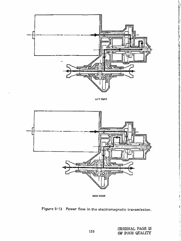
LG'V GEAR
HIGH GEAR
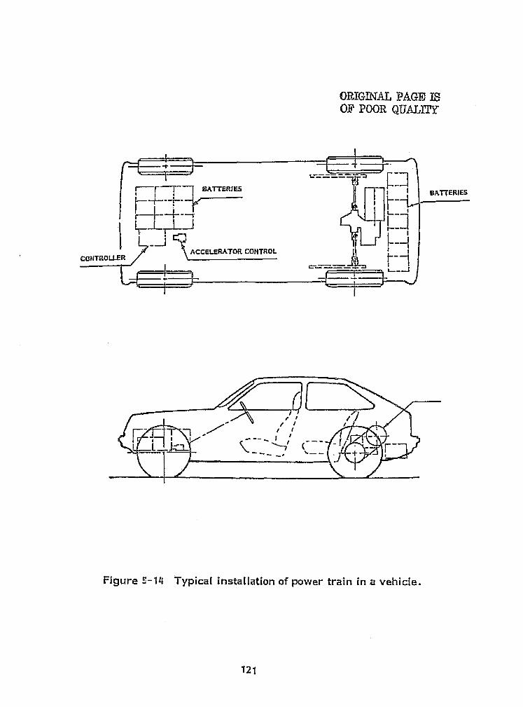
121
I
a
s =
` ORIGINAL PAGE ISOF POOR QUALITY f '
fi
^---^--4_-s !! B&TTERIES
1
CaNTROLt RACCEi BATOR CIOMOL
I
t
—Ir r
Figure S-14 Typical installation of power train in a vehicle.
^. r Y1.
4!.
ti
f '
i
i.
I
ti`
Ii

of19
Figure 5-15 Tooth type electromagnetic 3-speed transmission.
ORIGINAL PAGE ISOF POOR QUALITY
122
if

.A 1 '.
6.0 CONCLUSIONSf
This report has presented a preliminary design of an electric vehiclepower traits based on an objective assessment of the state -of-the-art, andhas identified and evaluated technical advances which can Improve vehicleperformance. The primary standard of performance was range over theSAE J227a schedule D driving cycle.
Most state-of-the-art electric vehicles are conversions of conventionalhighway vehicles. Very few completely original designs exist. Prototypessuch as the Copper Development Association town car and the McKeeSundancer, however demonstrate that carefully designed, lightweightvehicles can achieve superior performance.
Several state-of-the-art AC and DC motors are available in the size andpower range required. However, the only state-of-the-art controllerscommercially available are for DC series wound motors.
One technique of optimizing the range of an electric vehicle over astop and go driving cycle Is to match the motor characteristics to the loadthrough an efficient, lightweight rnultiratio automatic transmission. Thenumber of useable components Is quite [Imlted and Include modifiedconventional transmissions and an electrically controlled, V-belt, continuouslyvariable system. A promising alternate design Is based on off-the-shelf,
l ^.
i
electrically activated clutches. I
The recommended state-of-the-art power train design employs an j
18 kw (24 hp) DC series wound motor, SCR controller, V-belt CVT, drumbrakes, radial-ply tires and regenerative braking. A power train based on 1
a separately excited shunt wound DC motor will achieve about 20% greaterrange over the SAE cycle than one with a series wound motor. In order toImplement this system, technical development is needed In the areas ofhigher speed, shunt wound motors and electrical controllers featuringboth armature and field control.
Even with power train components which are perfectly efficient, ahighly streamlined 1.633 kg (3600 lb) electric vehicle, with state-of-the-art tires, would have a range of only 98 km (60 mi) over the SAE cycle.Its order to significantly extend range, Improved batteries, expanded_use of lightweight materials and low rolling resistance tires are needed.
nri -
123
REFERENCES
1. Adier, C.A., ed. Electric Vehicles at a Glance, McGraw-Hill,1978.
2. Schwartz, H.J., "The Computer Simulation of Automobile UsePatterns for Defining Battery Requirements for Electric Cars",NASA TMX-71900.
3. Koch, W, H . , "The Route to Control: Electronics", Electra-Technology, May, 1968.
4. Foote, L. R. and Hough, J.F., "An Experimental Battery PoweredFord Cortina Estate Car," SAE 700024.
S. Brennand, J., "Performance Standards for- Electric Vehicles,"NATO/CCMS f=ourth International Symposium on AutomotivePropulsion Systems, Washington, V.C., 1977.
fi. Electric Vehicle Association of Ohio, Files.
7. Busi, J.D. and Turner, I_.R., "Electric Vehicle Research,Development and Teclznglogy-Foreign," Defense IntelligenceAgency, Washington, D.C., June, 1975.
a. Hietbrink, E.H., et al., "Dual Battery Electric Powerplant",SAE 710234.
9. Boeing Vertol Company, "Light Rail Vehicle", 1975.
10. "Preliminary Results of Baseline Tests of Five Electric Vehicles".Electric Vehicle Project Office, NASA-- Lewis Research Centpar,C;eveland, Ohio October 15, 1976.
11. Hat-hay, W.C. and Bozek, J., "Baseline Test Data for the EVAElectric Vehicle, 11th IECEC, American Institute of ChemicalEngineers, N.Y.C., 1976.
124
REFERENCES(^Untrd^
IL Stwvice kind Technical Data Winual, Electric Vehicle Assuclatasittia orpt^ritod, clevelmd " 01110.
13, Hnrhay. W.C., Personal Communication. 1977,
14, "I3atironlc Specifigati€ans 16 , F3attrdnic, Truck Corporati€Nn, Buyertown,Pwnsylvania.
15, 11 01W Electric Autos". CJI. Waterman Industriv!,, Athol, Massachusetts
16, Marmon, D,L., "Dana Corporation Electric. Vehicle Program", DanaElectric vehicle Symposium, 1,qn.
17. Dowgialle, E.J., Spellings, I.R. and Make W,i-i., "Battery PoweredJeep) and Van Performance", SAE 770387.
16, "Electric Specifications Model DJ -5t:", AM Genoral Corporation,Wayne, hilchig*an,
19. "Citicar Spocificntions", Sebring Vanguard, Inc„ Sebring, Florida,197 r^ .
20. "The Electric Citic:ar", C011s€Eme1 • Reiazar •ts, October, 1976.
21, bro%val, D. ii . , "Hybrid Battery System", SAE 710236.
22. Wakefield, E,1-i. "An AC Electric drive Vehicle", IEEE Transactionson Industry Applications, Vol. IA 10, Nu. 5. September October, 1974
23. Greene, J.E,, " A Summary Report can t he Experimental Evaluatti^nof the Mors li Eloctrl€; AuttaizK)bilol l . Corn€ll Aeronautical Laboratory,Inc,. Eluffaia, New York.. February, 196 .
125
4 : ...... ._.-. ^_..- ,r-^`L^'.T^-.cy.awN^+•gsbr^•9 ».^.1 -"^.-t 4 _^ )
F
}
4
I
r7
126
REFERENCES(Cont,d)^
24. Mao, K . W. and Hwang, G.J ., "Development of Electric VehiclesIn Taiwan", l lth IECEC, American institute of Chemical Engineers,N.Y.C. 1976.
25. Harding, G.G., "Design of Electric Commercial Vehicles for Production",SAE 770388.
26. "Development of Electric Vehicles In Japan", Agency of industrialScience and Technology, Ministry of International Trade and Industry,Ocotober, 1973.
27. "The Development of Electric Vehicles in Japan", Electric Vehicles,March, 1976.
28, Imal, K., " Development of Electric Vehicles at Toyota", FourthInternational Electric Vehicles Symposium, Dusseldorf, 1476.
29. Wrench, N .S , and Porter, D . R. , "User Experience with the EnfieldCar", Fourth International Electric Vehicle Symposium, Dusseldorf, 1976.
30. Griffith, J .T., "Performance of an Electric Van Pitted with a Hydro-dynamic Torque Converter Transmission", Fourth international ElectricVehicle Symposium, Dusseldorf, 1976.
31. Martland, L., Lynes, A.E. and Foote C . R , , "The Ford Comuta - AnElectric Car for Use in City and Suburb". SAE 680428.
32, Aicock, D.N., "Understanding Solid - State Variable - Frequency PowerSupplies for Variable - Speed Pumping", Power, January, 1477.
33. Aitendorf, J P. Kalberiak, A. and Sarldakis, N., " A ComparisonBetween a Pick -Up Van with internal Combustion Engine and an ElectricPick-Up Van", Third International Electric Vehicle Symposium,Washington, D.C., 1974.
REFERENCES(Cont'd)
34, Aitendorf, J.W., Werner, F, and SIracke, K.H., "PreliminaryResults of Trials of Electrically Driven Commercial Vehicles",Fourth International Electric Vehicle Symposium, Dusseldorf, 1976.
3S, Cutberlet, H., Hares, H. and Schnell nt. H,, "Simple Electric D1 Ivwith Secondary Gear Drives, Conception and Operating Results",Fourth International Electric Vehicle Symposium, Dusseldorf1576, =
36. "Elcar Electric Model 4000", Elcar Corporation, Elkhart, Indiana, 1975,
F 37. "SRF Flywheel Electric Combi Truck", SRF, Jerusalem, Isreal.
38, Gumbleton, J .J ., at al . , "Special Purpose Urban Cats", SAE 690461. t
39 • Gates, D. and Focobel lo, M . , "Electric Van for Metropolitan Service",SAE 730249.
j.; 40. Armstrong D. and Pocobello, M,, "A Quiet, Efficient Controller forElectric Vehicles", SAE 750470, } #
41. Pocobello, M. and Armstrong D., "The Cop'er Electric Town Car", I ,SAE 760071.
3 'r42, McKee, R.S., et al., "Sundancer: A Test Coed Electric Vehicle",
i SAE 770188. C '..
+43. Fuqua, B. , "Could This Be the One?", Southwest Alrlines Magazine, aAugust, 1976.
44. Goldman, W.E., "The Design and Development of a Third-Generation1r!
i Electric Vehicle", SAE 720110.
CIS. Goldman, W.E., "Development of a Second Generation Electric HighwayVehicle and Support Equipment", Second International Electric VehicleSymposium, Atlantic City, New Jersey, 1971.
Yi)j
f,
i
1}
127
r ^
1 218
hr \
i
r T
1 .'L1 4^1
t
_ 1
1L i L'
L
46.
REFERENCES..^^^or^t'd)
' IT,# 3 Vale SpeciFicatlons", `i'ranspartation Systems Laboratory.Bedford. Massachusetts, 1974.
117, Jones, C3. Jr. and Nola, F J i, "Mability Spstems Activity for Lunarl:ovors at NAgA TM `-64M. Seplu)ber, 9,1971,
di 3. Klockner, K, lR,, "Modt^ling and Tfestinq of Storage Batteries",
SAL 750261.
Taylor, D.Fi and Slwtsi , E.tj,, "The Dynamic Chavacteri:ation titlead-Acid Dattorles for Vthlcle ApplicationSO% SAE 73025-1 , .`
Hox-lo. L,A,, "Some Dischavile Charactoristics of Load-Acid ^trttc^ritsAIEU Transat.tion:s. Volume 3, Part R. WY. C,, Now York, March. 195 r". ^
si'
J,3 ne. MG, . "The Sohavlar of Lead -Acld Sattorivs Usidor Pulsed E'alschrar e Candithrns", Tenth intol ,nationaI Dower Souret3s Symposium,
A.Brighton, C-rleliaild. 1976. 4
i^Cunningham. M,, "',A\tC-Hobbs Converter brings, ralectric Van Nearor `k ,ivoality", Motor Transport. Septt`rriber 12. 1915. E; t
53, Antony,mutts, "Traction Drivo"' r
Sri, Kraus J, H, "An Autonvtivo CV T. " Mechanical En ineerin ry ,October. 19'76,
S5, Riley, R Q.. "Are Electric Cor YOU 0n i'UIld". MC-CIzania IlltrsU`MVd.i't`I,^rtrar^ , 19 f r , 4 '
56, i^ro ectiire s cif_t^onfiorence on Fire RollincI Resistance, Akron, Ohio,
57. layman. B.Jr., "'lire Rolling Resistance Meznwrtments From Coast - ^ F
Down Tosts", SAE 760153,
11 9 ,
."0i
51,
SL
ca
1
REFERENCES
:a
55, el€zmming. D.A, tmd Bonier%, P.A., "Tine Testing for Rolling;V Resistance and Fuel Economy", SAE 7SW7, i
59, Shepard. P.D.. "The 'Effect of a Tit-a's Reinfzrcing Material on RollingResistance", SAE 770333.
60, Shuldiner, H.. "Elliptic Tire Stretches Your Gas Mileage", PopularScience, Novembor, 1977.
61. SAE Electric Vehicle Test Procedure J227 a.
62. Drennand, J . , "Refinement of Electric Car Performance Estimates",General Research Corporation, Santa Barbara. California, August, 1976.
63. Foote, L.R, at al„ "Electric Vehicle Study", Report No. SR-73-132,Ford Motor Company, October 25, 1973.
64. Murphy, GJ., "Considerations in the Design of Drive Systems forOn-the-Road Electric Vehicles", Proceedings of the IEEE, Volume 60,No, 12, December, 1972.
65. Patre;cca. G., "Research on an A.C. Drive for an Electric City Car",Third International Electric: vehicle Symposium, Washington, D,C., 1974.
129
e
13
r3ISLlCfaf`.APHY
Amato. C,.l,, "Effiect of Pulsing Gurrents an Sy,,Aem 1: fficienQy%MME Trams-actions on Indvstry and General Applicatims. Vol, ICA -$.No, 5, Sept..;,0Q , 190,
Ammumann. F , L , , "Question;; to Ask ALvut Batteries Proposed forE-Imtrlc Car's", S F, '4100021,
Ar onsm, RM1 R, o 11 4P 's Querent Program". Electric Fuol FrcapuisimCorporatIon, Detrolt. Michigan, 194.'1,
""act, from Oblivion", Machine Desiv, Oct. 17, 1974,
gadfw, C. and PILrst, ti, G.. "Electric Propulslan Systems for Road VehiclesState r:^f the Art and Present- Day Problems". Third International Electric``ehiclt^ S^ rzi ?^^sium, Washington, D , C , . 1 Q" tr 1
Balthasar, P^ P. and Reimers. E,, "The Integrated l'o`ner Switch".IFEE Transactions on lndwstry Applications. Vol. IA-12. No. 2.ltlarc.'April 1:17c
laQm an n B, and Cell. G, H,, "Electric Gar Drives-Design Considerations".SAF, TN111,
Blumhtr jj. P, N„ "Powertroln Simulation: A Taal for the Pes1gn andl valuatk4n of Lngink, Control Strateqies in Vehicles". SAL 7601W
Bmdley. D, A,. Clark, C, D,. Davls. F. M. and Jones, D. A,."Adjustable- FrNuency invertors and their Application to Variable-SpeedDrivos". Proc, IEL, VQI, Ill. No, 11, Nov, 1964.
Cairans, Lr J . and Yew, &1.. "Liec.tric Vehicle Over vie-W', 11th ILCEC,Amorlmi lnstitutecatChemical Engineers, N.Y.C,, 1976,
Chanu. H, L,. Fedewa, W. L. and Mahoney, ..1. E , , "An AnalyticalStwd io!f Trdrismissk )n lklodifications as RelMtd tk% Vehicle Ferformainceand Economy",y", SAL 770418,
130
FJ(
P: 4 ad
P
i
f{a
^,l
SIBLIOGRAPHN j4
^^entir^ueE3, 1'''
laristlanson. C, C., "batterlos for Electric Vt ^hlcics ll , Sr~ond InternationalSiectric Vehicle Symposium. AtIntitle City. N,J,, 1 ,R 1.
Cochvat, Heurtin arad Wolff. "Experiments tan :a Trial Serles of Electricvelliales", 'third international Eir-Nwtric Vehicle Symposium. Washington.ri.c.. Ian.
^. .
ri)avls, p ,l)„ O'Connell, L.G., Worntm-, S.E,, f:aymird, A.E. andRoWIL%, SM.. "The Battery - flywheel Hybrid Electric Power Systemfor Near-Term Application". UCID-1 099. Lowronce Uvormor e Ltatatt ratury. ,
- Livermore. California. April 15. 1976,
Davis, P.l E. "Rick)-Dtan't tt`;aik". Second International Electric VehicloSymposium, Altantic City, N .J . , 1971.
._ Dilrr':arZcc^s^;e, L. J.. "better Nt)edlL i3e-arings fir Universal r ots", The .
C
Tarrington Comp,uay, Bearings Dheislon, Torrington, Conn.
Dilauren. o. A., "Noodle 5earings in Pl anotar y gear' Trains", The Senrine) < ,^a Unginaer, Rcpr°int, Vo P 19, Numbers 1 and 2. I
Q.
Domann, t--1, and Renner. S., 11 E\ orienwe with Irlc-%Arie ©rivos t't.lr Vehicles".Third Intermational Eloctr}c Vehlicle Symposium, Washington, D.C., 1974.
{ DuCharme. R. T. and htxuwa . V, J. , "De vo lopraat`nt ctt ;a i„ightw-eii-Liilt Small
Car Disc, drake Systc% m i^,ir lratcrraat}ttrt,aE Usac^jc^''. SAE 70184, i
f I trc gr.r. G.L. , et tai. , "Mcat Engint , Mochanicai Energy-Storagt^ Hybrid i,Prtpul5itan Systtms for VOiiclos", The, John Htopkins University. Silver ISpring, Maryland, March 1972.
Gunton, IV. li. and Norton, P. R,, "C►uidesi}rio Spt^cificatlon tier UrbanR all Cars". The SoLeIng Vertal Company, Philadelphia ` €`a, M arch 14"3.
3
l l Electric eliii4les: A}taliecarapti, l^iectric Vehif-.le Council. N,Y.C., a`

r^4
r ^ ti.
f
.5
S^^T((I
Yrt
^^^ t
^;I BIBLIOGRAPHY
(Continued)
"Electric Vehicle Test [procedure", SAE J227A.
k x .^b
a-2
Eleventh lnWesoclety Energy Conversion Engineering Conference Proceed-ineers, N,Y.C., N.Y., Sept. 1976.` In s, American Institute of Chemical En. g r
"REV Controls", Electric Vehicle News, August 1973.
Ewing, J. S„ "Motors for Electric Vehicles", Second International Electric`t Vehicle Symposium, Atlantic City, N.J., 1971 .
Geizr • ke, G., "Pick a Needle: Bearing", Product Encdineerincg, Auq, 31, 1964,
Gelb, G ,H , . et al . , "An Ele ctromechan!cat Transmission for Hybrid VehiclePower- Trains- Design and Dynamometer Testing", SAE 710235.
Gelb, G.H. et al , , "resign and Performance Characteristcs of a HybridVehicle Power Train". SAE 690169.
O 'General Electric: Electric Vehicle Motors", General Electric, Erie Pennsyl-vania.
George, J. Fl, E . , Stratton, L. J . and Acton, R . G . , "Prospects for ElectricVehicles: A Study of Low-,Pollution Potential Vehicles-Electric", ArthurD. Little, Inc., Cambridge, Mass., Ma y 15, 1965,
Goeriach, V., "Relation Between Efficiency and Range of Electric Vehicles",NASA TT F-16, 520, Washington, D.C., December 1975.
Guess, R. H, and Lustenader, E. L„ "Development of a High Per=formanceand Light4veight Hybrrd Flywhc:el;'6attery Powered Electric Vehicle Drive".Fourth [rite mationaI Electric Vehicle Symposium, Dusseldorf, 1976.
BIBLIOGRAPHY(Continued)
Gurwicx, D., "Control and Charging Systems for Electric Vehicles",Second. International Electric Vehicle Symposium, Atlantic City, N. J . ,1971.
Hafer, P,RF , "The Electric Multistop Fleet Delivery Vehicle-Fact orFantasy", SAE 7507x.
Hagey, G. and Hamilton, W.. "The Future Role of Electric Land Transporta-tion in The United States", SAE 7&0118.
Harding, G. G., "Design of Electric Commercial Vehicles fbr Production",SAE= 770388.
Hartman, A. W., "Series-Paral lei Ing Variable Voltage Motor Controllers",H. B. Electrical Mfg, Co., Inc. , Mansfield, Ohio, March &, 1974.
Heise, C, J., "Dual Turbine-Battery Electric Vehicle Drive System",7th lntersoclety Energy Conversion Engineering Conference, N.Y.C.,N.Y., 1972.
Henry, G. F., "A Vehicle Control System for Urban Electrics", Thirdinternational Electric Vehicle Symposium, Washington, D. C., 1974.
Herbert, G. F. and Anderson, A. E., "Power Requirements of ElectricVehicles", SAE 710 238.
Hess, W. L., "Morgantown Project Vehicle Electrical System", SecondInternational Electric Vehicle Symposium, Atlantic City, N.J., 1971.
Hey, J. C., "Technological Trends in Power Semiconductors Significantfor Electric Vehicle Controls", SAES 720108.
Hirschfeld, F„ "Electrochemical Energy Conversion", MechanicalEngineering, .tune 1977,
Honda, S., et al., "Clean Transportation for New 'Towns DAIHATSU ElectricVehicles in the Senboku Area", SAE 770385.
133
i
134
BIBLIOGRAPHY(Continued)
Hull, J. R., "Rolling Element Bearings in Passenger Car Automatic Trans-missions-1967 Edition", SAE 670048.
Hull, J. R., "Design of Raceway Stofaces for Use with Torrington Needleand Roller Bearings", The Torrington Company, Torrington, Conn.
Inagaki, M., "Electric Vehicle Development in Japan", First InternationalElectric Symposium, 1969.
Ishihara, T. and Hasimoto, M., "A New Concept of Power Train forElectric Vehicle", AN-75-007517, Soc. des Ing. de L'Antomob--Paris.
Johnston, R, W., "Modulating Inverter System for Variable-Speed InductionMotor Drive (GM Electrovair 11) ", IEEE Transactions on Power Apparatusand Systems, Vol. PAS-88, No. 2, Feb. 1969.
Jones, C.S. Jr., et al., "Traction Drive System Design Considerationsfor A Lunar Roving Vehicle", SAE 700023,
Kahlen, H., "Van Drive with Electronic D.C. Choppews and MechanicalGear Box", Fourth International Electric Vehicle Symposium, Dusseldorf,1976.
Kahlen, H. and Weigel, W. E., "Comparative Measurements of DifferentElectric Drives for an Experimental Motor Vehicle", Third InternationalElectric Vehicle Symposium, Washington, D.C., 1974.
Ka.mada, K., et al . , "New Lead-Acid Batteries for Electrical Vehicles jand Approach to their Evaluation Method", Third International ElectricVehicle Symposium, Washington, E.C., 1974.
f t
King, W. W. and Collins, G. C., "Electric-Wheel Vehicle PropulsionSystem", SAE 690071.
Kintigh, S. S., "ABC's of SCR Controllers", Instrumentation Technology, FFeb. 1976. I t
t ^` }
i E
} r ^
BIBLIOGRAPHY(Continued)
E
Klein, E. A., and Norris, G. A., "Hydrostatics Tackle Tough New Jobs",Machine Design, Aug. 25, 1977.
Koch, W. H. and Eames, E. B., "Experimental Electric Vehicles", f=irstInternational Electric Vehicles Symposium, 1969.
Krouse, J. K., "Belt Drives That Shift Themselves", Machine Design,Aug. 25, 1977.
Kucera, G. , et al. , "Nickel-Zinc Storage Batteries as Energy Sources forElectric Vehicles", SAE 750147.
Kusco, A. and Magnuson, L. T., "Vehicle Electric Drive Systems",SAE 660761.
Lawson, L. J., "The Practical Cycloconverter", Lear Siegler, Inc.,Cleveland, Ohio.
Liddle, S. G., "An Analytical Study of the Fuel Economy and Emissions ofa Gas Turbine-Electric Hybird Vehicle", SAE 760122.
Liles, A. W. and Fetterman, G. P. Jr., "Selection of Driving Cycles forElectric Vehicles of the 1990's", 111th IECEC, American Institute of ChemicalEngineers, N.Y.C. 1976.
Lindhorst, P. K. and Andreas, J. C., "Design and Application of TractionMotors for Electric Vehicles", SAE 740729.
Loeb, L, S., "The M,I.T. Electric Car", SAE '090118,
Margrain, P., "Usage of Highpower Transistors for Application in ElectricUrban Vehicles Controllers", Third International Electric Vehicle Symposium,Washington, D.C., 1974.
k - i
E
i^:a
F
{
1.
I
135
i
e
131BLIOCRAPHYfContinued)
hlcKechnie, R.M., "Simulation of l lectr• ic Drive Vehicles", Report 1973,U.S. Army Mobility Equipment Research and Development Center, PortBelvoir, Va., Nov. 1969.
Menga, P., "On-The-Road Evaluation of the Efficiency of Propulsion Systemof City Vans", Fourth International Electiric Vehicle Symposia n), Dusseldorf.1976.
Micidlebr~ook. R. D] , "The Countertran. A New Controller for TractionMotors", IEEE Industry Applicatlons Society Annual Meeting, Chicago,Oct. 1976.
Miner, D. K., "A Two-Year Service Test Comparison of Electric VersusGasoline Dower for Utility Vans", Fourth International Electric VehicleSymposium, Dusseldorf, 1975.
Murphy, G. J., "Motor Drives and Control Systems for Electric Vehicles".ASME 74-[)E-20.
Murphy, G. J., "The Deslgn and Development of a Var y with an A. C.Electric~ Drive", Second International Electric Vehicle Symposium, AtlanticCity, N.J., 1971.
Naydowskl, C, 0., Pohl, 0, and Skudelny, H, C„ "Studie* of ElectricVehicle Drives, Illustrated by the Example of an Urban Estate Car", FourthInternational Electric Vehicle Symposium, 1976.
Proceed_ In,s; Second I nternational Electric Vehicle Syf lum, AtlanticCity, New Jersey, 1971.
"Range and Pfarturrrtance breakthrough", Electric Vehicles, June 1974.
136
.r _v.
1
131BLIOGRAPHY(Continued)
Rippel, W. E., "Dual SCR. Chopper as a Motor Controller for an ElectricCar", IEEE Transactions on Vehicle Technology, Vol. VT-20, No. 2,May 1971.
Roesler, D. J. and Jokl, A. L., "A Rationale for Electric Drive Trainsfor Heavy-Duty Vehicles", SAE 700732.
Runde, W., "Discharge Data of Lead Batteries and Their Influence on theOptimization of the Storage Capacity of Electric Vehicles", NASA TT-F-16821.
Saar, D. A., "Semiconductor Applications and Limitations for ElectricVehicles", Third International Electric Vehicle Symposium, Washington,D.C., 1974,
Salihi, J. T., "An Inverter for Traction Applications", IEEE Transactions onIndustrial Applications, Vol. IA-8, No, J, Sept. 1977,
Salihi, J. T,, "Simulation of Controlled-Slip Variable-Speed InductionMotor Drive Systems", IEEE Transactions on Industry and General Appli-cations Vol. IGA-5, No, 2, March/April 1969.
Salihi, J. T., Agarwal, P. E. and Spix, G, J., "Induction Motor ControlScheme for Battery-Powered Electric Cat' (GM-Electrova 1 r I)", IEEE Trans-actions on Industry and General Applications, Sept./Oct. 1967.
Schaeper, H. R. A. and Farber, E. A,, "University of Florida ElectricAutomobile", ASME 71-WA/Sol . -4, 1971.
Sheridan, D. C., Bush, J. J. and Kuziak, W. R. Jr., "A Study of theEnergy Utilization of Gasoline and Battery-Electric Powered Special PurposeVehicles", SAE 760119.
Shipps, P.R., "Minimizing Electric Cars to Maximize Performance", 11thIECEC, American Institute of Chemical Engineers, N.Y.0 1976.
Siabiak, W. and Lawson, L. J., "Precise Control of a Three-Phase Squirrel-Cage Induction Motor Using a Practical Cycloconverter", IEEE Transactionson Industry and General Applications, Vol, IGA-2, No. 4, July/Aug. 1966.
137
BIBLIOGRAPHY__(Continued)
Smith, G. E., "Development of Electric Vehicles In Japan", Universityof Michigan, Anti Arbor, Mich, 1974,
Stockton, T. R., "Ford/ERDA Continuously Variable Transmission:Progress Report #9 11 , Ford Motor Company, Dearborn, Mich., 1975,
Taborek, J. J., Mechanics of Vehicles, Penton Publishing Co,, Cleveland,Ohio, 1957.
"The Storage Battery, Lead-Acid Types", Exide Power Systems Division,ESE [tic.
Thiele, T. N. and Moore, D. L., "Case History and Economic Study of anElectric Commuter Vehicle", Second International Electric Vehicle Symposium,Atlantic City, N. J . , 1971,
Thomas, R. and Zander, Ee., "Proposals for the f= urther Development ofEnergy Stora rJe Systems for Electric Road Vehicles", Fourth InternationalElectric Vehicle Symposium, Dusseldorf, 1976.
Thompson, M, A. and Walters, L. A„ "The Design of d--c Commutator Motorsfor High Performance Electric Vehicles", SAE 740169.
Thorton, R,D. "Design Considerations for an Electric Car", SAE 700070
i Ulbrich, E. A., "Application of a Shunt Motor and a 7 Cylinder Gasoline'lEngine as a Hybird Drive for an Automobile", 1Ith IECEC, Americanlnstiture of Chemical Engineers, N.Y.C., 1975.
Unnewehr, L. E. , "Electric Vehicle Systems Study", Third International(electric Vehicle Symposium, Washington, D.C., 1974.
Unnewehr, L. E., et al., "Hybrid Vehicle for f = uel Economy", SAE 760121
138
BIBLIOGRAPHY(Continued)
Vinal, G. W., Starage Batteries, John Wiley 8 Sons, Inc., N.Y.
Volpe, R. W., "D--C Electric Drive for Off--Highway Vehicles", SAE 660199.
Wagner, Rudolf, "Methods of Propulsion for- Electric Vehicles", ThirdInternational Vehicle Symposium, Washington, D.C., 1974.
Wakefield, E. H., The Consumer ' s Electric Car, Ann Arbor Science,Ann Arbor, Mich., 1977.
Walz, A. H., "Theoretical Approach to Electric Battery Vehicle Performance",Third International Electr ic Vehicle Symposium Washi ngton, D.C., 1974.
Warner, P., "A Purpose- Built Electric Taxi", SAE 760124.
Waters, W. C., "General Purpose Automobile Performance and Economy e'
Simulator". SAE 720043.
'!- Whitiaw, R, L„ "Two New Weapons Against Automobile Air Pollution:The Hydrostatic Drive and the Flywheel Electric LDV", ASME 72-WA; APC-5,1972.
Williams, K. R. "Energy Analysis and The Electric Car", SAE 760120.I
Wong, Harold Y., "DC In =3 - Phase Out in High Power Static Inverter",
111The Electronic Engineer, Sept. 1968. ?^
!
Wouk, V. and Sefger • , H. N . , "Design of Electric Automobile EmployingNickel-Cadium Batteries", SAE 690454. ^.
Yew, M. and McCulloch, D. E., "Small Electric Vehicie Considerations inView of Performance and Energy Usage", 11th IECEC, American Institute i 1
of Chemical Engineers, N.Y.C., 1976. ° 1
i^
139

NASA-C-168 (Rev. 10.75)
F
Iwi
i
j
i
r
w
)' 1
1
j ,
L
1. Report Nn, 2. Government Accession No. 3, Recipients CaUlog No.
NASA GR-135347
4. Title and Subtitle 5. Repan Date
Preliminary Power Train Design for A State-of-the-Art April 1978S. Perfuming Organization CodeElectric Vehicle
7. Aulrrorls) B. Pasiorming Organization Report No
Phillip Mighdoll and William F. Hahn10. Work Unit No.
S). Perfuming Organization Name and AddressDesign and Development Division
11. Contract or Grant No.Boor, Allen E Hamilton Inc.8801 Fast Pleasant Valley Road NA5 3-20595Cleveland, Ohio 44131 13. Type of Report and Poriod Covered
Contractor Report12. Sponsoring Agency Name and AddressU. S. Department of Energy
14. Sponwring Agency Code Report NoDivision of Transportation Energy ConservationWashington, D.C. 20545 DOE/RASA/0595-78/1
15. Supplementary NotesFinal Report - Prepared under Interagency Agreement EC-77-A-31-1044NASA Lewis Research Center, Cleveland, Ohio 44135Project Manager, F. F. McBrien, Transportation Propulsion Division
16. Abstract
Power train designs which can be implemented within the currentstate-of-the-art were identified by means of a review of existing electricvehicles and suitable off-the-shelf components. The affect of variousmotor/transmission combinations on vehicle range over the SAE .1227aschedule D cycle was evaluated. The selected, state-of-the-art powertrain employs a DC series wound motor, SCR controller, variable speedtransmission, regenerative braking, drum brakes and radial ply tires.Vehicle range over the SAE cycle can be extended by approximately 20%by the further development of separately excited, shunt wound DC motorsand electrical controllers. Approaches which could improve overallpower train efficiency, such as AC motor systems, are identified. However,future emphasis should remain on batteries, tires and lightweightstructures if substantial range improvements are to be achieved.
17. Key words (Suled by Authulsi)Electric vehicles; Power Train; SAE
18- Distribution StatementUnclassified - unlimited
Driving Cycle; DC Motors. Transmissions, STAR Category 85Tires DOE Category UC-98
1@. Security Omit. iuf this report) 20. 6utarrity C4awif. (of lhis page) 21. No. of Pages 22. Price'Unclassified Unclassified 140
For sale by the National Technical Information Service, Springfield. Virginia 22161
11, i
t : t
I