Preliminary Navigation Study
88
Preliminary Navigation Study Multnomah County | Earthquake Ready Burnside Bridge Project Portland, OR January 29, 2021
Transcript of Preliminary Navigation Study

Preliminary Navigation Study
Multnomah County | Earthquake Ready
Burnside Bridge Project
Portland, OR
January 29, 2021


Earthquake Ready Burnside Bridge Preliminary Navigation Study
Prepared for
Multnomah County Transportation Division – Bridges 1403 SE Water Ave Portland, OR 97214
Prepared by
HDR 1050 SW 6th Avenue, Suite 1800 Portland, OR 97204 T (503) 423-3700
Glosten 1201 Western Avenue, Suite 200 Seattle, WA 98101-2921 T (206) 624-7850
Contract# DCS-SVCSGEN-857-2019-conv
HDR Project #10144814


CERTIFICATION
The technical material and data contained in this document were prepared under the supervision and direction of the undersigned, as a professional engineer.
Signature Reserved for Final Version
Prepared by Zenzile Moore (Naval Architect)
Signature Reserved for Final Version
Checked by Matthew Lankowski (Subconsultant Project Manager, PE)
Signature Reserved for Final Version
Approved by Heather Catron (Consultant Project Manager)


Preliminary Navigation Study
Multnomah County | Earthquake Ready Burnside Bridge Project
January 29, 2021 | i
Contents
Executive Summary ....................................................................................................................1
1 Introduction .......................................................................................................................1
1.1 Overview of Navigation Requirements...........................................................................1
1.2 Purpose ...................................................................................................................3
1.3 Methods and Data Sources .........................................................................................3
1.3.1 Literature Review............................................................................................3 1.3.2 Site Visit........................................................................................................4 1.3.3 River User Master List .....................................................................................5
1.4 Maximum River User Clearance Requirements...............................................................5
1.5 Bridge Design States ..................................................................................................6
2 Existing Navigation Use and Requirements ............................................................................7
2.1 Existing Bridge and Cable Crossing Clearances .............................................................7
2.1.1 Governing Navigation Limitations ......................................................................8
2.2 Navigation Channel .................................................................................................. 10 2.2.1 Waterway Layout and Geometry ..................................................................... 10 2.2.2 Hydrology and Waterway Natural Flow............................................................. 12 2.2.3 Waterway Depth and Elevation Fluctuations ..................................................... 13 2.2.4 Maintenance Dredging .................................................................................. 15 2.2.5 Guide Clearances ......................................................................................... 16 2.2.6 Channel and Waterway Alignment................................................................... 16
3 Future Development and Adopted Plans .............................................................................. 17
3.1 Portland Urban Plan History ...................................................................................... 17
3.2 Willamette Greenway Plan Goal and Objectives ........................................................... 17
3.3 Central City Plan...................................................................................................... 18
3.4 Oregon’s Statewide Planning Goals & Guidelines ......................................................... 18
3.5 River Renaissance ................................................................................................... 19
3.6 River Plan............................................................................................................... 19
3.7 Development Impacts on River .................................................................................. 21
4 Burnside Bridge Clearances............................................................................................... 22
4.1 Overview ................................................................................................................ 22
4.2 Commercial Users ................................................................................................... 23
4.2.1 Waterborne Commerce Statistics .................................................................... 33
4.3 Recreational Users................................................................................................... 34
4.4 Government Users ................................................................................................... 36
4.5 Bridge Clearance Recommendations .......................................................................... 38
4.5.1 Recommended Vertical Clearance Elevation..................................................... 38 4.5.2 Recommended Horizontal Clearance............................................................... 39 4.5.3 Clearance Window........................................................................................ 42 4.5.4 Navigation Impacts and Recommendations ...................................................... 42
5 Earthquake Response Vessels ........................................................................................... 44
5.1 Overview ................................................................................................................ 44
5.2 Summary of Findings................................................................................................ 44

Preliminary Navigation Study Multnomah County | Earthquake Ready Burnside Bridge Project
ii | January 29, 2021
5.2.1 Initial Response............................................................................................ 44 5.2.2 Considerations of Deep Draft Vessels .............................................................. 47
6 Conclusions and Recommendations.................................................................................... 48
6.1 Minimum Recommended Elevation............................................................................. 48
6.2 Minimum Recommended Horizontal Clearance ............................................................ 48
6.3 Bridge Width ........................................................................................................... 48
6.4 Impact of Clearance Requirements on Bridge Design States .......................................... 49
7 References...................................................................................................................... 50
Tables
Table 1. Most Restrictive Clearances of Bridge Design States ...........................................................2
Table 2. Horizontal Clearance Requirements of Impacted Tug and Barge River Users...........................5
Table 3. Maximum River User Elevations and Horizontal Clearance Requirements ...............................5
Table 4. Required Burnside Bridge Clearances at Various Design States ............................................6
Table 5. Willamette River Bridges and Crossings, Mouth to Mile 25.9 .................................................7
Table 6. Most Restrictive Horizontal Clearances on Willamette River ..................................................9
Table 7. Most Restrictive Elevations on Willamette River ..................................................................9
Table 8. Most Restrictive Clearances on Willamette River ............................................................... 10
Table 9. Willamette River Discharge ............................................................................................ 13
Table 10. Willamette River Tidal Stations...................................................................................... 14
Table 11. Willamette River Guide Clearances................................................................................ 16
Table 12. Navigation Channels on Willamette River ....................................................................... 17
Table 13. River Plan Reaches and Themes .................................................................................. 20
Table 14. River Plans Projects Potentially Impacting River Traff ic, Flow, or Footprint........................... 21
Table 15. Horizontal Clearance Requirements of Impacted Tug and Barge River Users ....................... 26
Table 16. Assumed Horizontal Clearance if a Single Leaf Must Be Closed......................................... 41
Figures
Figure 1. Horizontal Clearance between Bridge Piers and Upriver/Downriver Bridge Width ....................2
Figure 2. Distribution of River Users...............................................................................................3
Figure 3. Elevation and Corresponding Horizontal Clearance for Each River User Type.........................4
Figure 4. Glosten Staff on River Survey Near Ross Island and St. John’s Bridge ..................................4
Figure 5. Horizontal Clearance between Bridge Piers and Upriver/Downriver Bridge Width ....................6
Figure 6. Willamette River Basin (green), Willamette River (black), and Oregon Counties .................... 11
Figure 7. Willamette River Waterway Layout in Vicinity of Burnside Bridge......................................... 12
Figure 8. Expected Tidal and Flood Elevations at Morrison Bridge (WRM 12.8) .................................. 14
Figure 9. River Plan Reaches ..................................................................................................... 20
Figure 10. Distribution of River Users ........................................................................................... 22
Figure 11. Tug and Barge Users - Required Vertical Clearance Elevations (top) and Required Horizontal Clearance Widths (bottom) ............................................................................... 24
Figure 12. Foss (left) and AAC (right) Facilities on the Willamette River............................................. 26

Preliminary Navigation Study
Multnomah County | Earthquake Ready Burnside Bridge Project
January 29, 2021 | iii
Figure 13. Cruise Ship Users - Required Vertical Clearance Elevations (top) and Required Horizontal Clearance Widths (bottom) ............................................................................... 27
Figure 14. The Oregon Maritime Museum Sternwheeler Portland ..................................................... 29
Figure 15. Visitors and Fleet Week Vessels - Required Vertical Clearance Elevations (left) and Required Horizontal Clearance Widths (right)..................................................................... 30
Figure 16. MS The World ........................................................................................................... 31
Figure 17. Diagram of Fleet Week Vessel Mooring Plan.................................................................. 32
Figure 18. Fleet Week Vessels with Air Drafts Greater Than 100 Feet That Transited Through the Burnside Bridge, 2008 – 2018.......................................................................................... 32
Figure 19. Upper Willamette and Yamhill River commerce between 2007 and 2016 ............................ 33
Figure 20. Recreational users - Required Vertical Clearance Elevations (top) and Required Horizontal Clearance Widths (bottom) ............................................................................... 35
Figure 21. Government Users - Required Vertical Clearance Elevations (top) and Required Horizontal Clearance Widths (bottom) ............................................................................... 37
Figure 22. Elevation Requirements of All Known River Users........................................................... 39
Figure 23. Horizontal Clearance Requirements of All Known River Users .......................................... 40
Figure 24. Elevation Requirement and Corresponding Horizontal Clearance Requirement for
Each River User Type .................................................................................................... 42
Figure 25. Air Gap Sensor on Gerald Desmond Bridge in Long Beach, California ............................... 43
Figure 26. Representative Derrick Barge ...................................................................................... 47
Appendices
Appendix A. River User Master List ........................................................................................... A-1
Appendix B. River Users Removed from Analysis ........................................................................ B-1
Appendix C. Select River User Navigation Feedback.................................................................... C-1

Preliminary Navigation Study Multnomah County | Earthquake Ready Burnside Bridge Project
iv | January 29, 2021
Acronyms, Initialisms, and Abbreviations
AAC Advanced American Construction
AEP Annual Exceedance Probability
BPS City of Portland Bureau of Planning and Sustainability
CFR Code of Federal Regulations
CRD Columbia River Datum
EPA U.S. Environmental Protection Agency
EQRB Earthquake Ready Burnside Bridge
FEMA Federal Emergency Management Agency
FHWA Federal Highway Administration
FR Federal Register
LCDC Oregon Land Conservation and Development
Commission
MHHW Mean higher high water
MHW Mean high water
MLLW Mean lower low water
MLW Mean low water
MTSRU USCG Marine Transportation System Recovery Unit
NAVD 88 North American Vertical Datum 1988
NEPA National Environmental Policy Act of 1969
NGVD 29 National Geodetic Vertical Datum of 1929
NOAA National Oceanic and Atmospheric Administration
ODOT Oregon Department of Transportation
OHW Ordinary high water
PNERC Pacif ic Northwest Ecosystem Research Consortium
SAR Search and rescue
USACE U.S. Army Corps of Engineers
USC United States Code
USCG U.S. Coast Guard
USGS U.S. Geological Survey
WRM Willamette River Mile

Preliminary Navigation Study
Multnomah County | Earthquake Ready Burnside Bridge Project
January 29, 2021 | ES-1
Executive Summary
The Burnside Bridge in Portland is being made “earthquake-ready” as part of the
Earthquake Ready Burnside Bridge project. The purpose of this report is to summarize
the impacts to navigation of the Burnside Bridge replacement projects during temporary
and permanent bridge phases. This report provides substantial input towards the
complete Navigation Impact Report prepared by HDR as part of a U.S. Coast Guard
(USCG) Bridge Permit Application.
Recommended Clearances
The USCG requirement to enable 100 percent of vessel traf fic to safely transit under the
bridge drives the clearance recommendations within this study. The recommendations
herein ref lect the minimum clearances that will allow all vessel traf f ic to safely transit the
bridge.
The recommended minimum clearance elevation for all bridge design states is
167 feet above the NAVD 88 datum. The recommended horizontal clearance for all
bridge design states is 205 feet.
The recommended vertical clearance is based on the maximum air draf t of all known
river users above ordinary high water (OHW), the water level accepted as a design
elevation by the USCG and USACE.
For short-term reductions to these clearances during construction, it is reasonable to
assume that the USCG will grant temporary deviations to these clearance dimensions,
as evidenced by the many recent rehabilitation projects. These temporary deviations,
however, are on a case-by-case basis only and should be limited to days and a few
weeks rather than months. Temporary deviations may require agreements f rom af fected
river users.
Bridge Design States
The objective of this study was to determine minimum clearance requirements
independent of bridges or any other man-made obstructions. However, many river users
could not articulate their clearance requirements without a starting point to consider. This
starting point was provided as a set of Bridge Design States, representing minimum
existing and proposed clearances. A variety of bridge designs are being considered for
this project. All bridge designs fall into one of four states:
• Existing. The current Burnside Bridge. This bascule bridge has dif ferent vertical
clearances in the lowered and raised positions.
• Temporary. A temporary construction phase consisting of a vertical lif t bridge with
limited clearances. This phase will ultimately lead to a dif ferent bridge design state.
• Permanent Retrofit. Earthquake retrof it of the current bascule Burnside Bridge, with
no impact on existing clearances in the lowered and raised positions .
• Permanent Replacement. The permanent design for a replacement Burnside Bridge,
with permanent changes to existing clearances.

Preliminary Navigation Study Multnomah County | Earthquake Ready Burnside Bridge Project
ES-2 | January 29, 2021
Table 1 presents the most restrictive elevation and horizontal clearance of the bridge
designs being considered for each design state as communicated by the HDR Bridge
Design Team1.
Table 1. Most Restrictive Clearances of Bridge Design States
Design State Elevation Horizontal
Clearance
Bridge Width
(ft. upriver / downriver)
Existing 69 ft. above NAVD 88
(closed); Infinite (raised)
205 ft. 86 ft.
Temporary 167 ft. above NAVD 88
(raised)
165 ft. 220 ft. to 390 ft.
Permanent Retrofit 69 ft. above NAVD 88
(closed); Infinite (raised)
205 ft. 86 ft.
Permanent
Replacement
69 ft. above NAVD 88
(closed); Infinite (raised)
205 ft. 150 ft. to 195 ft.
Elevation refers to distance above North American Vertical Datum 1988 (NAVD 88) or
the Columbia River Datum (CRD), as noted. Horizontal clearance refers to the clear
distance between bridge piers. This study assumes the center of the navigation channel
will remain the same as the existing Burnside Bridge. Bridge width refers to the
upriver/downriver distance for transiting under the bridge (Figure 1).
Figure 1. Horizontal Clearance between Bridge Piers and Upriver/Downriver Bridge Width
Source: Google Earth
River Users
In this study, a river user is a public or private entity expected to transit the Burnside
Bridge in a vessel during and/or af ter Burnside Bridge modification. A river user may be
an individual (such as a private vessel owner) or a group (such as a company, marina, or
organization).
1 Bautista, R. (email) [HDR], “RE: EQRB NEPA: Navigation Study Report Rev P1 Rev 2 Package Comments,” 14 June 2019

Preliminary Navigation Study
Multnomah County | Earthquake Ready Burnside Bridge Project
January 29, 2021 | ES-3
As part of this study, 84 river users potentially af fected by a change in clearance of the
Burnside Bridge were contacted or researched. Elevations and horizontal clearance
requirements were ultimately obtained for 47 river users. These 47 users are a
representative subset of the thousands of actual river users who may transit under the
Burnside Bridge. They fall into three main types: commercial, recreational, or
government, as shown in Figure 2.
Figure 2. Distribution of River Users
Elevation and horizontal clearance requirements are provided by the river users
themselves. These requirements represent their stated minimum space needed to safely
transit the bridge. The basis for these requirements, such as the season and water
surface elevation, varies f rom river user to river user.
Elevation and horizontal clearance requirements combine to form a clearance window.
Figure 3 displays the clearance windows for the vessels with the largest clearances in
each user type.

Preliminary Navigation Study Multnomah County | Earthquake Ready Burnside Bridge Project
ES-4 | January 29, 2021
Figure 3. Elevation and Corresponding Horizontal Clearance for Each River User Type
The height and width of each box in Figure 3 correspond to the required elevation and
horizontal clearance (centered on the navigation channel) for each vessel.
Impact of Recommended Clearances on Bridge Design States
All bridge design states currently satisfy the recommended elevation of 167 feet above
NAVD 88.
Three bridge design states satisfy the recommended horizontal clearance of 205 feet:
existing, permanent retrof it, and permanent replacement.
The 165-foot horizontal clearance of the temporary bridge design state would impose an
operations impact on three known river users, which would be mitigated via tug-assist, as
stated below:
• Combined Forestry reported that they could not transit safely, but one or two tug
assists could mitigate the impact. However, tug assists would not guarantee safe
transit for Combined Forestry.
• Advanced American Construction (AAC) reported that they would require a tug assist
for safe transit.
• Shaver Transportation reported that they would require a tug assist on a case-by-
case basis.

Preliminary Navigation Study
Multnomah County | Earthquake Ready Burnside Bridge Project
January 29, 2021 | ES-5
• Table 2 summarizes the horizontal clearance requirements of these impacted tug
and barge river users.
Table 2. Horizontal Clearance Requirements of Impacted Tug and Barge River Users
User
Horizontal
Clearance
Requirement
Temporary Bridge
(considering a 165 ft. to 390 ft. width range)
Combined Forestry &
Marine Services, Inc.
205 ft. No safe transit, but tug assist may mitigate the impact
Shaver Transportation 200 ft. Safe transit with 1 tug assist (on case-by-case basis)
AAC 185 ft. Safe transit with 1 tug assist
Moreover, the Columbia River Pilots advised against narrowing the Burnside Bridge. The
Burnside Bridge is the narrowest bridge in the Sellwood Reach (the Willamette River
downstream of the Sellwood Bridge). The temporary bridge would become the most
restrictive horizontal clearance on the waterway. Any reduction to its horizontal clearance
at either the temporary or permanent phases will require negotiation with these impacted
river users.
Bridge upriver/downriver width (Figure 1) also has navigation impacts. If a replacement
bridge requires a temporary bridge during construction, then transit width could range
f rom 220 feet to 390 feet, subject to how the contractor might construct the bridge. Some
river users would require a tug assist due to this extensive bridge width. The transit width
of the permanent bridge would range f rom 150 feet to 195 feet, subject to the exact
length of the pier fender system to be implemented. River users do not anticipate
requiring regular tug assists to navigate this bridge width. Depending on future project
work and river conditions, occasional tug assist may be needed. One river user
recommended widening the horizontal clearance to aid navigation through the longer
bridge corridor.
Based on feedback f rom participating river users and vertical and horizontal clearance
requirements, several recommendations are presented for the design and construction of
the Earthquake Ready Burnside Bridge project:
• Clear navigation signage for both commercial and recreational vessel operators.
• Dedicated transit lane for small recreational craf t such as kayaks and stand-up
paddleboards.
• Real-time vertical clearance gauge to inform vessel operators whether they clear the
bridge at any given moment or river level.

Preliminary Navigation Study Multnomah County | Earthquake Ready Burnside Bridge Project
ES-6 | January 29, 2021
This page is intentionally left blank.

Preliminary Navigation Study
Multnomah County | Earthquake Ready Burnside Bridge Project
January 29, 2021 | 1
1 Introduction
1.1 Overview of Navigation Requirements
According to 33 CFR Part 329, navigable waters of the United States are those waters
that are subject to the ebb and f low of the tide and/or are presently used, or have been
used in the past, or may be susceptible for use to transport interstate or foreign
commerce. A determination of navigability, once made, applies laterally over the entire
surface of the waterbody, and is not extinguished by later actions or events which
impede or destroy navigable capacity (33 CFR §329.4, Def inition of Navigable Waters of
the US, 2019).
In ef fect, once a waterway has been deemed navigable, its navigability may not be
diminished. This report analyzes the historical and possible future use of the Willamette
River at the Burnside Bridge to determine the minimum clearances required to ensure
navigability is not diminished, based on existing and anticipated future traf fic in the
Sellwood Reach (the Willamette River downstream of the Sellwood Bridge).
Code of Federal Regulations
33 CFR Subchapter J sets the requirements for the locations and clearances of bridges
and causeways over navigable waters (33 CFR §33.114-116, Navigation and Navigable
Waters, 2019). Part 114 establishes the District Commander (USCG) as the reviewer of
bridge permit applications, and details permitting procedures. Special protocols are
provided in Part 115 if a bridge is determined to be an unreasonable obstruction to
navigation. Drawbridges and bridge lighting are also reviewed in Part 116.
33 CFR Subchapter P governs Ports and Waterway Safety (33 CFR §33.162-163,
Navigation and Navigable Waters, 2019). Specif ic detail concerning the Willamette River
is provided in Part 162. The District Commander of the Thirteenth Coast Guard District is
given administrative supervision and the responsibility to enforce emergency regulations
concerning navigation, such as speed regulations during f looding or construction. Part
163 limits the length of seagoing barge tows in inland waters.
U.S. Coast Guard Bridge Permit Application
The USCG provides written approval of the location and plans for proposed bridges or
causeways over navigable waterways (USCG 2016). The Bridge Permit Application is
the medium for the USCG written approval. The three primary components of the Bridge
Permit Application are:
1. Proposed bridge description.
2. Environmental documentation.
3. Plan sheets.
In addition to the above, applicants must provide a Navigation Impact Report. This
report summarizes current and prospective navigation on a waterway and analyzes the

Preliminary Navigation Study Multnomah County | Earthquake Ready Burnside Bridge Project
2 | January 29, 2021
navigational impacts of the proposed bridge designs. Data for this report is collected by
both Bridge Permit applicants and the USCG, and may include:
• Visits, including site visits, ride-alongs, and public meetings.
• Written Communications, such as public notices for comment, advertisements, and
surveys.
• Research, including review of bridge tender logs, USACE Engineer Manuals design
guidance, and waterborne commerce statistics.
The Navigation Impact Report draws on this data to describe key navigation aspects:
• Nearby structures, including bridges, federal navigation projects, marine facilities,
and harbors of refuge.
• Waterway characteristics, including bends in the waterway, hydraulic conditions,
atmospheric conditions, and guide clearances.
• Waterway users, including service facilities, and vessels for emergency response,
defense, maintenance, commerce, and recreation.
• Alternate waterway routes.
Proposed developments that will af fect navigation aspects are also discussed.
U.S. Coast Guard Direct Guidance
In developing this Navigation Study, USCG has advised key study elements through
meetings and email communication. Based on this guidance, the navigable waterway is
assumed to run f rom bank to bank on the Willamette River. No federally maintained
channel exists near the Burnside Bridge to restrict the width of the navigable waterway
(Section 2.2.6).
USCG stated that 100 percent of vessel traf f ic must be able to safely transit the
permanent and temporary bridge, unless a compelling reason exists otherwise. An
example compelling reason would be a written agreement between the City of Portland,
Multnomah County, and the river user unable to pass. The agreement would state all
parties agree that the restricted river user will not be able to transit the Burnside Bridge
for the foreseeable life of the permanent or temporary bridge. As part of the user survey,
restricted use was discussed with the river users and some users may be unwilling to
reduce their transit rights if it af fects their projects at that time. Formal restricted use
agreements were not pursued as part of this study.
Ultimately, the USCG requirement to enable 100 percent of vessel traf fic to safely transit
the permanent and temporary bridge led to the vertical and horizontal clearance
requirements in this report. These clearance requirements ref lect the minimum
clearances that will allow all known river users to safely transit the bridge. The USCG
stresses that a bridge replacement or modif ication project of this duration and with this
many stakeholders will have evolving stakeholder needs over time. Establishing
navigability requirements is necessarily an iterative process. Navigability requirements
must be periodically revisited throughout the project to ensure no previously unknown
river users have become known, or known river user needs have changed.

Preliminary Navigation Study
Multnomah County | Earthquake Ready Burnside Bridge Project
January 29, 2021 | 3
Single-Leaf Closures
Temporary single-leaf closures are a possibility during the construction of any bascule
bridge. USCG grants permission for a temporary single-leaf closure via two mechanisms:
• Temporary Deviation, for closures under 180 days in duration (minimum 90-day
application period).
• Temporary Rule, for closures exceeding 180 days in duration with no maximum
duration (minimum three or four month application period).
These mechanisms are fully detailed in 33 CFR §117.35. They represent deviation f rom
the normal operating rules of the Burnside Bridge, detailed in 33 CFR §117.897(c)(3)(iii).
Temporary Rules and Temporary Deviations are totally separate f rom the USCG Bridge
Permit Application described above.
Both Temporary Deviations and Temporary Rules require 100 percent consent f rom
vessel traf f ic. For example, if a particular river user cannot safely transit the bridge during
the single-leaf closure, the Temporary Deviation or Temporary Rule application must
include permission f rom that af fected user to forego transit during the closure period .
USCG will independently check potentially af fected users to confirm the applicant has
suf f iciently canvassed river users. River users who are anticipated to be af fected by
single leaf closures of the Burnside Bridge are detailed in Section 4.5.2.
USCG approval does not depend on time of year or the number of consecutive
Rules/Deviations. USCG approval does depend on consent from affected users. To this
end, the Temporary Rule / Temporary Deviation applicant is encouraged to consider
mitigation with af fected users. For example, if the applicant provides alternate moorage
for af fected users, these users may be more likely to consent to forego transit during the
closure period.
1.2 Purpose
This report summarizes the impacts to navigation of the Burnside Bridge replacement
projects during temporary and permanent bridge phases. This report provides substantial
input towards the complete Navigation Impact Report prepared by HDR as part of a
USCG Bridge Permit Application.
1.3 Methods and Data Sources
1.3.1 Literature Review
Glosten reviewed background materials in three areas: regulations, river hydrology, and
urban development. Key materials in each area include:
• Regulations
o USCG Bridge Permit Application Guide.
o USCG Guide Clearances.
o Code of Federal Regulations.
o Oregon Department of State Lands.

Preliminary Navigation Study Multnomah County | Earthquake Ready Burnside Bridge Project
4 | January 29, 2021
o Oregon Department of Land Conservation and Development.
• River Hydrology
o USGS tidal and f lood elevations.
o National Geodetic Survey vertical datums.
o National Oceanic and Atmospheric Administration Charts.
o Department of the Army Corps of Engineers Waterborne Commerce Statistics.
• Urban Development
o City of Portland River Renaissance.
o City of Portland River Plan.
o Oregon Department of Land Conservation and Development Oregon’s Statewide
Planning Goals & Guidelines.
o Portland-Milwaukie Light Rail Project Final Environmental Impact Statement,
Navigation Study.
Glosten also summarized existing bridge clearances upstream and downstream of
Burnside Bridge. The literature provided a foundational understanding of the Willamette
River. Multnomah County bridge opening data was researched but the data obtained did
not prove to be valuable.
1.3.2 Site Visit
On 26 March 2019, Glosten conducted a site visit to physically assess the Burnside
Bridge, traf f ic patterns, and local vessels. The site visit was comprised of a 20-mile
pontoon boat cruise f rom the St. John’s Bridge (Willamette River Mile (WRM) 5.8) to the
Willamette Falls (approximately WRM 26). On the cruise, Glosten staf f visually inspected
the Burnside Bridge, other bridges, local sites and businesses, and vessel traffic . Staff
also visited businesses and marinas on Multnomah Channel and the Columbia River
near the mouth of the Willamette. The visit provided a current snapshot of operations on
the Willamette River. Glosten staf f also performed land-based visual inspections of the
Burnside Bridge, other nearby bridges, and sites and businesses in the area.
Figure 4. Glosten Staff on River Survey Near Ross Island and St. John’s Bridge

Preliminary Navigation Study
Multnomah County | Earthquake Ready Burnside Bridge Project
January 29, 2021 | 5
1.3.3 River User Master List
The Literature Review and Site Visit informed development of the River User Master List .
The List contains 84 river users potentially af fected by changing Burnside Bridge
clearances. Users without signif icant marine assets in the project area or who declined
response were typically omitted from further study (Appendix B).
Required information was found via other methods for some unresponsive users . Those
users were included in the evaluation of elevation and horizontal clearance requirements
despite being unresponsive.
The List provides the following information (as available) for each river user:
• Brief description.
• Contact information (phone and email).
• Contact history for this Navigation Study.
• Elevation requirement at the Burnside Bridge.
• Horizontal clearance requirement at the Burnside Bridge.
1.4 Maximum River User Clearance Requirements
Elevations and horizontal clearance requirements were ultimately obtained for 47 users
(Appendix A). Table 3 presents the maximum requirements f rom that group.
Table 3. Maximum River User Elevations and Horizontal Clearance Requirements
User Clearance Controlling River User
Maximum River User Vertical
Clearance Elevation
147 ft air draft (Elevation
167 ft. above NAVD 88 at
Burnside Bridge)
Fleet Week (USCG Waesche)
142 ft air draft (Elevation
162 ft. above NAVD88 at Burnside Bridge)
M/V The World
Maximum River User Horizontal Clearance Requirement
205 ft. Combined Forestry and Marine Services, Inc.
The maximum river user elevation equals the minimum bridge elevation requirement.
The maximum river user horizontal clearance requirement equals the minimum bridge
horizontal clearance requirement. The requirements in Table 3 ref lect river user needs at
the time of this study. River users and their requirements may change over time as the
project develops. Thus, the maximum requirements are subject to change during the
course of the project.
Bridge upriver/downriver width (Figure 1) also has navigation impacts. The transit width
of the alternative with a temporary bridge could range f rom 220 feet to 390 feet, subject
to how the contractor might construct the bridge. Some river users would require a tug
assist due to this extensive bridge width. The transit width of the permanent bridge would

Preliminary Navigation Study Multnomah County | Earthquake Ready Burnside Bridge Project
6 | January 29, 2021
range f rom 150 feet to 195 feet, subject to the exact length of the pier fender system to
be implemented. River users do not anticipate requiring regular tug assists to navigate
this bridge width. Depending on future project work and river conditions, occasional tug
assist may be needed. One river user recommended widening the horizontal clearance
to aid navigation through the longer bridge corridor.
1.5 Bridge Design States
The objective of this study was to determine minimum clearance requirements
independent of bridges or any other man-made obstructions. However, many river users
could not articulate their clearance requirements without a starting point to consider. This
starting point was provided as a set of Bridge Design States, representing minimum
existing and proposed clearances.
The bridge designs for the Earthquake Ready Burnside Bridge project fall into one of four
states. Table 4 presents those states and their dimensions, which represent the most
restrictive elevation and horizontal clearance of all bridge designs within each state.
Table 4. Required Burnside Bridge Clearances at Various Design States
Design State Vertical Clearance
(Elevation)
Horizontal
Clearance
Bridge Width
(ft. upriver/downriver)
Existing 69 ft. above NAVD 88
(closed); Infinite (raised)
205 ft. 86 ft.
Temporary 167 ft. above NAVD 88
(raised)
165 ft. 220 ft. to 390 ft.
Permanent Retrofit 69 ft. above NAVD 88
(closed); Infinite (raised)
205 ft. 86 ft.
Permanent
Replacement
69 ft. above NAVD 88
(closed); Infinite (raised)
205 ft. 150 ft. to 195 ft.
Elevation refers to vertical clearance above North American Vertical Datum 1988
(NAVD 88) or the Columbia River Datum (CRD), as noted. Horizontal clearance refers to
the clear distance between bridge piers. Width refers to the upriver/downriver distance
for transiting under the bridge (Figure 5).
Figure 5. Horizontal Clearance between Bridge Piers and Upriver/Downriver Bridge Width

Preliminary Navigation Study
Multnomah County | Earthquake Ready Burnside Bridge Project
January 29, 2021 | 7
Note: The width shown does not include any temporary bridge works anticipated during construction.
Source: Google Earth
The elevations of all bridge states meet or exceed the maximum elevation of all river
users.
The 165-foot horizontal clearance of the temporary bridge state would impose an
operations impact on three known river users, which would be mitigated via tug-assist, as
stated below:
• Combined Forestry reported that they could not transit safely, but one or two tug
assists could mitigate the impact. However, tug assists would not guarantee safe
transit for Combined Forestry.
• AAC reported that they would require a tug assist for safe transit .
• Shaver Transportation reported that they would require a tug assist on a case-by-
case basis.
2 Existing Navigation Use and Requirements
2.1 Existing Bridge and Cable Crossing Clearances
Fif teen bridges and four cables cross the Willamette River between mouth and the
Willamette Falls (Table 5). Elevations when comparing bridges are given with respect to
the Columbia River Datum (CRD), which varies along the length of the Willamette River.
Table 5. Willamette River Bridges and Crossings, Mouth to Mile 25.9
Bridge/Interference Milepost
Elevation
ft. above
CRD*
Horizontal
(Closed) ft.
Elevation
(Raised) ft.
above CRD
Horizontal
(Raised) ft.
St. Johns Bridge 6.0 205 1068 - -
St. Johns Railroad Bridge
(Burlington Northern RR
Bridge 5.1)
7.0 54 499 200 499
Fremont Bridge 11.1 163 928 - -
Broadway Bridge 11.7 90 251 Infinite 251**
Steel Bridge 12.1 26 205 161 205
Existing Burnside Bridge 12.4 64 205 Infinite 205**
Temporary Burnside Bridge (Proposed)
12.4 TBD 165 162 165
Permanent Retrofit Burnside Bridge
(Proposed)
12.4 64 205 Infinite 205**
Permanent Replacement
Burnside Bridge
(Proposed)
12.4 64 205 Infinite 205**
Morrison Bridge 12.8 69 209 Infinite 185

Preliminary Navigation Study Multnomah County | Earthquake Ready Burnside Bridge Project
8 | January 29, 2021
Table 5. Willamette River Bridges and Crossings, Mouth to Mile 25.9
Bridge/Interference Milepost
Elevation
ft. above
CRD*
Horizontal
(Closed) ft.
Elevation
(Raised) ft.
above CRD
Horizontal
(Raised) ft.
Hawthorne Bridge 13.1 49 200 159 200
Marquam Bridge 13.5 102 350 - -
Marquam Bridge
(*Centermost)
13.5 120 220*** - -
Tilikum Crossing Bridge 13.7 63 651 - -
Tilikum Crossing
(*Centermost)
13.7 77 150*** - -
Ross Island Bridge 14.0 90 330 - -
Ross Island Bridge
(*Centermost)
14.0 120 100*** - -
Cable (East Channel) 14.3 83 - - -
Cable (West Channel) 14.3 123 - - -
Cable 16.3 103 - - -
Cable 16.4 91 - - -
Sellwood Bridge 16.6 72 270 - -
Lake Oswego Railroad
Bridge
20.0 74 280 - -
I-205/Abernethy Bridge 25.5 76 325 - -
Oregon City Bridge 25.9 74 181 - -
* CRD is 5 ft above NAVD88 at Burnside Bridge.
** Represents horizontal clearance in the shipping channel at waterline. The horizontal clearance between raised bridge spans may be less.
*** Represents horizontal clearance of the tallest section of the bridge; the full bridge has a larger horizontal
clearance at a lower elevation.
2.1.1 Governing Navigation Limitations
A key component of the USCG Bridge Permit Application is a comparison of the subject
bridge to existing structures on the waterway (USCG 2016). This section provides that
comparison. The Application focuses in particular on whether or not the subject bridge
will become the most restrictive structure on the waterway, with regard to either
horizontal clearance or elevation.
Horizontal Clearance
The proposed Burnside Bridge with a temporary bridge would be the most restrictive
horizontal clearance on the waterway for that period (Table 6). Neither the existing
bridge, nor the permanent replacement bridge, nor the permanent retrof it bridge would
be the most restrictive horizontal clearance on the waterway. Two bridges currently have

Preliminary Navigation Study
Multnomah County | Earthquake Ready Burnside Bridge Project
January 29, 2021 | 9
more restrictive horizontal clearances than the existing and permanent b ridge design
states. These are the Oregon City and Hawthorne Bridges, as shown in Table 6.
Table 6. Most Restrictive Horizontal Clearances on Willamette River
Bridge Milepost Elevation
ft. above
CRD*
Horizontal
ft.
Elevation
(Raised) ft.
CRD*
Horizontal
(Raised) ft.
Temporary Burnside
Bridge (Proposed)
12.4 TBD 165 162 165
Oregon City Bridge 25.9 74 181 - -
Hawthorne Bridge 13.1 49 200 159 200
Existing Burnside Bridge 12.4 64 205 Infinite 205**
Permanent Replacement
Burnside Bridge
(Proposed)
12.4 64 205 Infinite 205**
Permanent Retrofit
Burnside Bridge
(Proposed)
12.4 64 205 Infinite 205**
Steel Bridge 12.1 26 205 166 205
Morrison Bridge 12.8 69 209 Infinite 185
* CRD is 5 ft above NAVD88 at Burnside Bridge.
** Represents horizontal clearance in the shipping channel at waterline. The horizontal clearance between
raised bridge spans may be less.
Elevation
The permanent replacement and temporary bridge design states exceed the navigational
elevation of thirteen existing structures on the waterway (Table 7).
Table 7. Most Restrictive Elevations on Willamette River
Bridge/Interference Milepost
Elevation
ft. above
CRD*
Horizontal
ft.
Elevation
(Raised) ft.
above
NAVD 88
Horizontal
(Raised) ft.
Sellwood Bridge 16.6 72 270 - -
Lake Oswego Railroad
Bridge
20.0 74 280 - -
Oregon City Bridge 25.9 74 181 - -
I-205 / Abernethy Bridge 25.5 76 325 - -
Tilikum Crossing
(Centermost)
13.7 77 150 - -
Cable (East Channel) 14.3 83 - - -
Cable 16.4 91 - - -
Cable 16.3 103 - - -

Preliminary Navigation Study Multnomah County | Earthquake Ready Burnside Bridge Project
10 | January 29, 2021
Table 7. Most Restrictive Elevations on Willamette River
Bridge/Interference Milepost
Elevation
ft. above
CRD*
Horizontal
ft.
Elevation
(Raised) ft.
above
NAVD 88
Horizontal
(Raised) ft.
Ross Island Bridge
(Centermost)
14.0 120 100 - -
Marquam Bridge
(Centermost)
13.5 120 220 - -
Cable (West Channel) 14.3 123 - - -
Hawthorne Bridge 13.1 49 200 159 200
Steel Bridge 12.1 26 205 161 205
Permanent Replacement
Burnside Bridge
(Proposed)
12.4 64 205 Infinite 205**
Temporary Burnside
Bridge (Proposed)
12.4 TBD 165 162 165
* CRD is 5 ft above NAVD88 at Burnside Bridge.
** Represents horizontal clearance in the shipping channel at waterline. The horizontal clearance between
raised bridge spans may be less.
The other two bridge states, existing and permanent retrof it, significantly exceed the
above elevations and are not shown in Table 7.
Governing Clearances
Table 8 summarizes the most restrictive clearances on the Willamette River between the
mouth and Willamette Falls listed in Table 6 and Table 7. The Burnside Bridge temporary
bridge would be the most restrictive horizontal clearance on the waterway.
Table 8. Most Restrictive Clearances on Willamette River
Bridge Milepost Elevation ft.
above CRD*
Horizontal
ft.
Minimum Clearance on
Waterway?
Temporary Burnside
Bridge
12.4 162 165 Yes, for Horizontal
Clearance
Sellwood Bridge 16.6 72 270 Yes, for Vertical Clearance
* CRD is 5 ft above NAVD88 at Burnside Bridge.
2.2 Navigation Channel
2.2.1 Waterway Layout and Geometry
The 187-mile Willamette River initiates near Eugene, Oregon, runs through Portland,
Oregon, and terminates at the Columbia River estuary, the largest f luvially d ominated
estuary in the Pacif ic Northwest. Lying in the Willamette Valley, the river drains an area
of 11,200 mi2 in the Willamette River Basin (Figure 6). With an average width of 75 miles,

Preliminary Navigation Study
Multnomah County | Earthquake Ready Burnside Bridge Project
January 29, 2021 | 11
the Willamette River Basin accounts for 12 percent of Oregon state area, 13 of 36
Oregon state counties, and 70 percent of Oregon state population (FEMA 2010, PNERC
2002, USACE 2017, Wherry 2018).
Figure 6. Willamette River Basin (green), Willamette River (black), and Oregon Counties
Source: Pacific Northwest Ecosystem Research Consortium (PNERC) 2002
The waterway layout in the vicinity of the Burnside Bridge impacts navigation. The
Burnside Bridge is situated just south of a bend in the Willamette River adjacent to
Downtown Portland (Figure 7). River users must navigate four bridges in close proximity
near this river bend.

Preliminary Navigation Study Multnomah County | Earthquake Ready Burnside Bridge Project
12 | January 29, 2021
Figure 7. Willamette River Waterway Layout in Vicinity of Burnside Bridge
The combination of waterway layout and bridge proximity increases the challenge of river
navigation when transiting the Burnside Bridge. As described by Advanced American
Construction, Inc., passability is “in relation to other bridges. Ultimately that’s what you
have to align with.” Additionally, the Columbia River Pilots noted that “narrowing the
approach on Burnside would make the approach to Steel Bridge even more dif f icult ”
(Appendix C).
2.2.2 Hydrology and Waterway Natural Flow
In the downstream portion of the Willamette River, f loodplains are narrow, the river
gradient is low, and the backwatering ef fect of the Columbia River is dominant (PNERC
2002). Flooding near Portland is linked in the spring to the Columbia River Basin
snowmelt f reshet, and in the winter to rainstorms and high f lows in the Columbia and
Willamette Rivers (FEMA 2010).
At Willamette Falls (WRM 26), the 1 percent annual exceedance probability (AEP)
regulated f low is 11,000 m3/s (Wherry 2018).
This study focuses on the downstream, or northern, portion of the Willamette River
between Willamette Falls (WRM 26) and the Columbia River (WRM 0). This portion of
the river f lows through a basalt trench formed by a series of lava f lows that pre-date the
uplif t of the northern Cascade Mountain Range. It has undergone little geomorphic
change over the last 150 years; river channels and islands have remained relatively
consistent (PNERC 2002).

Preliminary Navigation Study
Multnomah County | Earthquake Ready Burnside Bridge Project
January 29, 2021 | 13
Discharge at the proposed bridge is derived from USGS Station 14211720 Willamette
River at Portland, OR (Table 9, USGS, n.d.).
Table 9. Willamette River Discharge
Annual Mean Discharge, Average 33,312 ft.3/sec 1973 to 2017
Annual Mean Discharge, Minimum 21,170 ft.3/sec 1992
Annual Mean Discharge, Maximum 57,490 ft.3/sec 1996
2.2.3 Waterway Depth and Elevation Fluctuations
Willamette River Basin Datums
Three datums are commonly referenced throughout the Willamette River Basin (NOAA,
CREOFS, n.d., and Datums, n.d.):
• National Geodetic Vertical Datum of 1929 (NGVD 29). This vertical control datum
was originally established in 1929 as the Sea Level Datum of 1929, and re-
established with its current name in 1973. It was developed f rom the observed
heights of mean sea level at 26 tide gauges throughout the U.S. and Canada. In
1992, this datum was superseded by the North American Vertical Datum of 1988.
• North American Vertical Datum of 1988 (NAVD 88). This vertical control datum
was established in 1991, and developed f rom the height of the primary tidal bench
mark at a single station: Father Point/Rimouski, Quebec, Canada.
• Columbia River Datum (CRD). This non-tidal, def ined-gradient datum along the
Columbia River (between miles 23 ad 145) and the Willamette River (f rom WRM 0 to
WRM 27). USACE f irst established this low-water reference plan during a 1912
observational study. The zero reference for CRD lies below average low water, but
not at the lowest record. CRD was historically redef ined with respect to f irst
NGVD 29, and then NAVD 88.
The City of Portland Datum and Portland River Datum also appear on some survey
documents, but they are not used in this study.
Tidal and Flood Elevations
The United States Geological Survey (USGS) and National Oceanic and Atmospheric
Administration (NOAA) historically maintained three tidal stations in the downstream
portion of the Willamette River (Table 10).

Preliminary Navigation Study Multnomah County | Earthquake Ready Burnside Bridge Project
14 | January 29, 2021
Table 10. Willamette River Tidal Stations
Agency Station ID Location Date
Established
Date
Removed Datum
NOAA 9439221 Morrison Bridge 16 Oct 1940 28 Jan 2009 7.03 ft. abv
NAVD 88
USGS 14211720 Morrison Bridge 1 Oct 1988 - 5.01 ft. abv
NAVD 88
USGS 14207770 Willamette Falls 1 Oct 2007 - 3.51 ft. abv
NAVD 88
Source: NOAA, Station ID 9439221; USCG 1420770, 14211720, n.d.
Figure 8 displays tidal and f lood elevations in the Willamette River at Morrison Bridge
with respect to NAVD 88. Tidal data f rom NOAA Station 9439221 Morrison Bridge
provides the assumed tidal characteristics for Mean Higher High Water (MHHW), Mean
Low Water (MLW), and Mean Lower Low Water (MLLW). Ordinary High Water (OHW)
stage is derived f rom the USACE at the proposed bridge (USACE 2017). Flood
characteristics are provided by a 2010 Federal Emergency Management Agency (FEMA)
f lood insurance study (FEMA 2010).
Figure 8. Expected Tidal and Flood Elevations at Morrison Bridge (WRM 12.8)
Source: NOAA Station ID 9439221, n.d.; FEMA 2010
Preliminary Navigation Study
Multnomah County | Earthquake Ready Burnside Bridge Project
January 29, 2021 | 15
OHW is the water level that Portland USACE uses for planning purposes, based on the
high water mark naturally demarcated by vegetation along the river bank . OHW was
justif ied as a basis for the worst-case river level stage for the purposes of required
navigational clearance in the most recent navigation study in the area that was accepted
by the USCG (Tilikum Crossing).
Up to 13 feet of tidal f luctuation between OHW and MLLW is expected . Flood f luctuations
far exceed tidal f luctuations. A flood with a 10 percent chance of occurring in any year
(10-year f lood) exceeds MLLW elevation by 18 feet. A f lood with a 1 percent chance of
occurring in any year (100-year f lood) exceeds MLLW elevation by 25 feet. (FEMA
2010).
Flood Control
Four f lood control types are identif ied in the Willamette River Basin (FEMA 2010,
PNERC 2002, USACE 2017):
• Willamette Valley Project. Between 1941 and 1969, the U.S. Congress authorizing
the Willamette Valley Project through a series of Flood Control Acts . Under these
Acts, USACE constructed thirteen dams, reservoirs, and af f iliated inf rastructure in
the Willamette River Basin with 1.6 million acre-feet f lood storage capacity. This
system has not only reduced f lood elevation on the Columbia and Willamette Rivers,
but also aided navigation, irrigation, hydropower, water supply, pollution abatement,
f ish and wildlife, and recreation.
• Revetments. For more than a century, the Willamette River has been redirected and
its erosion slowed by placing large stones in riprap, wing def lectors, and levees.
USACE constructed and manages approximately half of the 96 miles of revetments.
While revetments may mitigate f loods and erosion at the installation site, they can
simultaneously expedite f loods and erosion in other areas.
• Seawall. The Portland Seawall is a concrete wall extending f rom the Steel Bridge
(WRM 12.1) to Hawthorne Bridge (WRM 13.1). Built in 1928, the railing of the wall
extends above 500-year f lood levels. However, f loods may still circumvent the
seawall downstream of the Steel Bridge.
• Nonstructural measures. In April 1972, Ordinance No. 134486 National Flood
authorized the participation of the City of Portland in the FEMA National Flood
Insurance Program. Under this resolution, building permit applications and
subdivision proposals are reviewed for f lood safety.
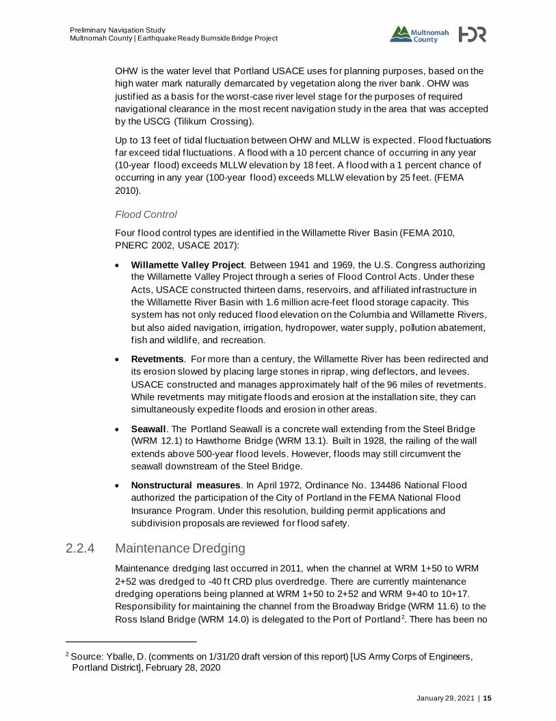
2.2.4 Maintenance Dredging
Maintenance dredging last occurred in 2011, when the channel at WRM 1+50 to WRM
2+52 was dredged to -40 f t CRD plus overdredge. There are currently maintenance
dredging operations being planned at WRM 1+50 to 2+52 and WRM 9+40 to 10+17.
Responsibility for maintaining the channel f rom the Broadway Bridge (WRM 11.6) to the
Ross Island Bridge (WRM 14.0) is delegated to the Port of Portland2. There has been no
2 Source: Yballe, D. (comments on 1/31/20 draft version of this report) [US Army Corps of Engineers, Portland District], February 28, 2020

Preliminary Navigation Study Multnomah County | Earthquake Ready Burnside Bridge Project
16 | January 29, 2021
recent channel maintenance in this stretch and none is currently planned3. See
Section 2.2.6 for a description of the federal navigation channel.
2.2.5 Guide Clearances
The USCG has established Guide Clearances for many navigable waterways in the
United States (USCG, n.d.). Bridges and causeways that satisfy these navigational
clearances are viewed favorably during the bridge permitting process. Table 11 provides
the USCG Guide Clearances for the Willamette River.
Table 11. Willamette River Guide Clearances
River
Segment Description Bridge Type
Clearance
Horizontal Vertical
WRM 0 – 11.6 Mouth to Broadway
Bridge Fixed 1,000 ft.
211 ft. abv NAVD 88
WRM 11.6 –
14.0
Broadway Bridge to
Ross Island Bridge
Fixed 500 ft. 171 ft. abv NAVD
88
Movable 250 ft. 71 ft. abv NAVD
88 (closed)
WRM 14.0 – 25.5
Ross Island Bridge to Abernethy Bridge
- None None
Source: USCG, n.d.
Existing bridges are not necessarily required to satisfy USCG Guide Clearances. Two of
four bridges in the f irst segment (WRM 0 – 11.6) do not satisfy vertical Guide Clearances
(St John’s Railroad Bridge, and the Fremont Bridge). Three of six bridges in the second
segment (WRM 11.6 – 14.0) do not satisfy vertical Guide Clearances (Marquam Bridge,
Tilikum Crossing Bridge, and Ross Island Bridge). Future bridges, however, are
encouraged to achieve these guide clearances, if practicable.
2.2.6 Channel and Waterway Alignment
The Willamette River Navigation Channel f rom WRM 0.0 to the Broadway Bridge
(WRM 11.6) is authorized to -43 feet CRD plus overdredge. The channel has a depth of
40 feet, and widths ranging f rom 600 feet to 1,900 feet. (USACE Portland District, 2003).
From the Broadway Bridge (WRM 11.6) to the Ross Island Bridge (WRM 14.0), the
authorized federal navigation channel is 30 feet CRD. The authorized channel width is
300 feet, however it is not currently delineated; thus, this study assumes no restrictions
on vessel access between riverbanks2.
Table 12 summarizes the navigation channels on the Willamette River.
3 Source: Super, G. (phone call) [Port of Portland], April 20, 2020.

Preliminary Navigation Study
Multnomah County | Earthquake Ready Burnside Bridge Project
January 29, 2021 | 17
Table 12. Navigation Channels on Willamette River
River Segment Description Active Federal
Navigation Channel?
Authorized Depth
(CRD)
WRM 0.0 – 11.6 Mouth to Broadway
Bridge Yes; active 43 ft.
WRM 11.6 – 14.0 Broadway Bridge to
Ross Island Bridge
Yes; active;
maintenance
delegated to Port of
Portland
30 ft.
WRM 14.0 – 25.5 Ross Island Bridge to
Abernethy Bridge Yes; active Varies
Source: Yballe, D. (comments on 1/31/20 draft version of this report) [US Army Corps of Engineers,
Portland District], February 28, 2020
The Willamette River above Portland and Yamhill River Channel runs upstream of
the Willamette River Navigation Channel f rom Portland to the Yamhill River. This USACE
Federal Navigation Channel is active but not maintained. The last recorded dredging
activity is 1990.
3 Future Development and Adopted Plans
3.1 Portland Urban Plan History
For more than thirty years, Portland has developed and re-developed urban plans
focused on the role of the Willamette River. Historic documents presenting these plans
include:
• Willamette Greenway Plan Goal and Objectives (1987).
• Central City 2035 Plan (1988, 2012, 2017).
• Oregon’s Statewide Planning Goals & Guidelines, Goal 15 (1973; 2010).
• River Renaissance (2001).
• River Plan (2010, 2020).
These plans are summarized in this section.
3.2 Willamette Greenway Plan Goal and Objectives
The Willamette Greenway Plan was developed in 1987 with a goal to protect and
enhance land qualities along the Willamette River (BPS 1987). It established boundaries
for the Willamette Greenway, and allocated areas within the Greenway by land use. This
plan introduced four types of overlay zones for Greenway land:
1. River Industrial
2. River Development
3. River Recreational
Preliminary Navigation Study Multnomah County | Earthquake Ready Burnside Bridge Project
18 | January 29, 2021
4. River Natural
The plan also included design guidelines and landscaping guidelines.
3.3 Central City Plan
The Central City 2035 Plan provides a development f ramework for portions of Portland’s
Central City regions (BPS 2017). Developments focused on the Willamette River include
increasing river setback to implement a River Environmental overlay zone, al lowing small
shops to activate the waterf ront, and encouraging riverf ront use.
3.4 Oregon’s Statewide Planning Goals & Guidelines
In 1973, the State of Oregon established a set of goals and guidelines focused on land
use and related topics (Department of Land Conservation and Development 2010).
Although Oregon’s Land Conservation and Development Commission (LCDC) directs the
statewide planning program, city and county governments have responsibility for the
implementation and execution of the land use goals and guidelines.
Goal 15 establishes the Willamette River Greenway Program, whose main objectives are
the protection, conservation, enhancement, and maintenance of land along the
Willamette River. This land is zoned according to eleven potential uses:
1. Agricultural lands.
2. Recreation.
3. Public access.
4. Fish and wildlife habitat.
5. Scenic qualities and view.
6. Protection and safety.
7. Vegetative f ringe.
8. Timber resource.
9. Aggregate extraction.
10. Development away f rom river.
11. Greenway setback.
The Oregon Department of Transportation (ODOT) prepares and maintains “inventories”
that record the boundaries of the above zones within the Willamette River Greenway.
Cities and counties that include the Willamette River Greenway must incorporate
boundaries into zoning maps. A draf t inventory was developed in February 2019 as part
of the River Plan (Section 3.6).
Preliminary Navigation Study
Multnomah County | Earthquake Ready Burnside Bridge Project
January 29, 2021 | 19
3.5 River Renaissance
River Renaissance Vision (2001)
Developed in 2001 on the 150th anniversary of Portland’s founding, this report
summarizes a future vision for the city of Portland.
The Vision is comprised of five central themes:
1. Assure a clean and healthy river for f ish, wildlife, and people.
2. Maintain and enhance our prosperous working harbor [sic].
3. Embrace the river as Portland’s f ront yard.
4. Create vibrant waterf ront districts and neighborhoods.
5. Promote partnerships, leadership, and education.
Public input is an important aspect of the Vision. In developing the Vision, the Portland
Bureau of Planning drew on feedback from planning events attended by over a thousand
Portlanders.
River Renaissance Strategy (2004)
This document ref ines the River Renaissance Vision by expanding each theme with
policy guidance, success indicators, and recommended actions.
3.6 River Plan
The current manifestation of the River Renaissance is the River Plan, a focused urban
planning project for the downstream Willamette River. Also derived f rom the 1987
Willamette Greenway Plan, Greenway zoning code, and Greenway design guidelines,
the River Plan was initially adopted by the Portland City Council in April 2006. Key
stakeholders guiding the River Plan include a voluntary citizen’s committee, ad -hoc task
groups, and technical advisers.
The River Plan divides the downstream Willamette River f rom the mouth (WRM 0)
through Elk Rock Island (WRM 19) into three reaches for future development (Figure 9,
Table 13).

Preliminary Navigation Study Multnomah County | Earthquake Ready Burnside Bridge Project
20 | January 29, 2021
Figure 9. River Plan Reaches
Table 13. River Plan Reaches and Themes
Reach Title Extent
The North Reach Portland’s Working
Waterfront
Mouth to Broadway Bridge
(WRM 0 to WRM 11.6)
The Central Reach The Region’s
Gathering Place
Broadway Bridge to Ross Island Bridge
(WRM 11.6 to WRM 14)
The South Reach Neighborhoods and
Natural Areas
Ross Island Bridge to Dunthorpe Neighborhood
(WRM 14 to WRM 19)
As of the writing of this Navigation Study, the River Plan current status includes:
• River Plan / North Reach court rulings. Af ter its adoption by the Portland City
Council in 2010, the River Plan / North Reach faced two years of legal proceedings
regarding the regulation of land for urban use in Oregon’s statewide land use
planning goals. Following this process, focus shifted to the River Plan / Central
Reach.
• River Plan / Central Reach in Central City 2035. In June 2018 the Portland City
Council adopted the Central City 2035 plan, which includes focused goals for the
Central Reach.

Preliminary Navigation Study
Multnomah County | Earthquake Ready Burnside Bridge Project
January 29, 2021 | 21
• Draft inventory. In February 2019, the River Plan team completed an updated draf t
inventory of natural resources in support of Oregon’s Statewide Planning Goals and
Guidelines (Section 3.4). The inventory contains maps that geographically present
regulatory, land use, ownership, environmental, recreation, historic, and cultural
information across all three reaches.
• Draft River Plan / South Reach. In January 2020, The River Plan / South Reach
draf t was released, which includes establishing a renewed vision for the area,
updating existing policies and regulations, identifying implementation actions, and
identifying future South Reach investments (City of Portland, 2020).
3.7 Development Impacts on River
Within the f ive River Renaissance themes, proposed River Plan projects address a broad
range of topics including industry, neighborhoods, recreation, and natural resources. The
development projects planned for each reach address the f ive central themes of the
River Renaissance Initiative. As shown in Table 14, select proposed projects would
specif ically af fect Willamette River traf f ic, flow, or footprint.
Table 14. River Plans Projects Potentially Impacting River Traffic, Flow, or Footprint
Project Description Planned Reach(es)
Contaminated site cleanup North Reach (Portland Harbor Superfund)
Recycling of brownfield and unoccupied sites North Reach; Central Reach (Zidell Marine Yard); South Reach (Ross Island restoration)
Riverbank treatment and planting North Reach
River channel maintenance and dredging North Reach; South Reach
Waterfront refurbishment North Reach (St. Johns, Linnton); Central Reach
(Centennial Mill)
New bridge (or bridge modification) North Reach (new bridge, or modifications to St.
Johns or Railroad Bridges; Hayden Island; Sauvie
Island)
New river ferry or river taxi system Central Reach
New cruise ship terminal Central Reach (Central City)
Projects identif ied in Table 14 are not guaranteed to occur, but should be monitored
during their development, potential construction, and execution. These projects may
af fect the vessels that call on the Burnside Bridge. Po tential impacts of these projects on
navigation elevation and horizontal clearance requirements include:
• Increased horizontal clearance requirement. All projects identif ied in Table 14 could
undergo a construction phase. This phase could increase tug and barge traf f ic similar
to that described in Section 4.2. Thus, all projects could increase traf fic with a large
horizontal clearance.

Preliminary Navigation Study Multnomah County | Earthquake Ready Burnside Bridge Project
22 | January 29, 2021
• Increased elevation requirement. A new cruise ship terminal could encourage larger,
taller passenger vessels to call on downtown Portland.
Additionally, River Plan projects must work in concert with the land use zones delineated
in the Goal 15 Inventory.
4 Burnside Bridge Clearances
4.1 Overview
In this study, a river user is a public or private entity expected to transit the Burnside
Bridge in a vessel during and/or af ter Burnside Bridge modification. A river user may be
an individual (such as a private vessel owner) or a group (such as a company, marina, or
organization).
As part of this study, 84 river users potentially af fected by a change in clearance of the
Burnside Bridge were initially contacted or researched. Users without signif icant marine
assets in the project area or who declined response were omitted f rom further study
(Appendix B). Elevations and horizontal clearance requirements were ultimately obtained
for 47 river users (Appendix A, Appendix C). These 47 users are a representative subset
of the thousands of actual river users who may transit under the Burnside Bridge.
Each river user is classif ied as one of the following:
• Commercial: includes tug/barge river users, shipyards, cruise operators, or other.
• Recreational: includes yacht clubs, sailing clubs, private vessels, or private marinas.
• Government: includes inf rastructure, regulatory, or emergency response.
As described in Figure 10, a majority of river users are commercial.
Figure 10. Distribution of River Users

Preliminary Navigation Study
Multnomah County | Earthquake Ready Burnside Bridge Project
January 29, 2021 | 23
Elevation and Horizontal Clearance Requirements
Elevation and horizontal clearance requirements reported in this section are provided by
the river users themselves. These requirements represent the minimum space needed
for the river user to safely transit the bridge. Unless otherwise stated, these
requirements imply safe transit without tug assist.
The basis for these requirements varies f rom river user to river user. Typically, the
elevation requirement derives f rom the river user’s highest vessel air draf t (distance f rom
waterline to highest point on vessel) expected to transit the Burnside Bridge.
Typically, the horizontal clearance requirement derives f rom the river user’s largest
vessel beam (vessel transverse dimension) expected to transit the Burnside Bridge. The
horizontal clearance requirement includes an additional margin for safe navigation
around river obstacles like bridge supports. Many river users specif ied either a complete
horizontal clearance, or a beam and safety margin. For those who did not, Glosten
estimated a horizontal clearance based on vessel length, beam, and typical navigational
practices.
For some users, such as operators who tow multiple barges side-by-side, the horizontal
clearance requirement may derive f rom the beam and safety margin of multiple vessels
transiting the bridge simultaneously. An individual barge may have a small beam, but if
the operator expects to tow two or three barges simultaneously, their horizontal
clearance requirement will signif icantly exceed an individual beam.
River user elevation and horizontal clearance requirements communicate river user
needs for safe transit with no operational impact. Minimization of navigational impact is a
key evaluation factor of the USCG for Bridge Permit Applications (Section 1.1).
4.2 Commercial Users
About two-thirds of all river users are classif ied as “Commercial.” These river users are
compensated for vessel operations on the Willamette River between the mouth and
Willamette Falls. They fall into three subcategories (Figure 10):
• Tug and barge: These river users operate tugboats, barges, and other large marine
assets to support towing, shipyard, and construction projects. About one-third of all
Willamette River users are tug and barge river users.
• Cruise: These river users transport paying passengers for day or overnight cruises,
or as part of launch services. About one-quarter of all Willamette River users operate
cruises.
• Visitors and Fleet Week: “Visitors” refers to large vessels that transit the Burnside
Bridge and require permitting through the Harbor Master. “Fleet Week” refers to the
set of Navy, sea, and other vessels that visit Portland during the annual Fleet Week
celebration in June.
Tug and Barge
Sixteen tug and barge river users were identif ied . Figure 11 depicts their air draf ts,
expected elevation requirements, beams, and horizontal clearance requirements.

Preliminary Navigation Study Multnomah County | Earthquake Ready Burnside Bridge Project
24 | January 29, 2021
(Brusco Tug & Barge declined to provide breadth or draf t information and is not included
in Figure 11).
Figure 11. Tug and Barge Users - Required Vertical Clearance Elevations (top) and Required Horizontal Clearance Widths (bottom)

Preliminary Navigation Study
Multnomah County | Earthquake Ready Burnside Bridge Project
January 29, 2021 | 25
At OHW, all tug and barge river users can safely transit beneath the inf inite and 167-foot
elevations of all bridge design states.
All tug and barge river users can safely transit the 205-foot horizontal clearance of the
existing, permanent retrof it, and permanent replacement bridge design states. This
precedent was established with the existing Burnside Bridge and the downstream Steel
Bridge, both of which have a 205-foot horizontal clearance and verif ied by the river user
survey.
The horizontal clearance requirements of three tug and barge users exceed the 165-foot
horizontal clearance of the temporary bridge state:
• Combined Forestry & Marine Services, Inc .: This river user prefers the existing
clearance of 205 feet. The reasons for this preference include:
o Horsepower limitations within the Combined Forestry f leet.
o River conditions near the Burnside Bridge. Eddies and boils prevail, and cause
vessels to track at an angle.
The 165-foot horizontal clearance of the temporary bridge in conjunction with a possible
390-foot bridge width is “a non-starter” for this river user. Although assist tugs may
mitigate the loss of work with such a bridge, Combined Forestry may still lose some
work. In contrast, a bridge width closer to 200 feet would impact 50 percent or more of
Combined Forestry operations.

Preliminary Navigation Study Multnomah County | Earthquake Ready Burnside Bridge Project
26 | January 29, 2021
• AAC: This general contractor would require a tug assist to safely transit the 165-foot
horizontal clearance and 390-foot width of the temporary bridge.
• Shaver Transportation: Shaver Transportation has stated that the 165-foot clearance
of the temporary bridge would require an assist tug on a case-by-case basis.
Table 15 summarizes the horizontal clearance requirements of these impacted tug and
barge river users.
Table 15. Horizontal Clearance Requirements of Impacted Tug and Barge River Users
User Horizontal
Clearance
Requirement
Temporary Bridge
(considering a 165 ft. to 390 ft. width range)
Combined Forestry &
Marine Services, Inc.
205 ft. No safe transit, but tug assist may mitigate the impact
Shaver Transportation 200 ft. Safe transit with 1 tug assist (on case-by-case basis)
AAC 185 ft. Safe transit with 1 tug assist
Figure 12. Foss (left) and AAC (right) Facilities on the Willamette River
One other tug and barge river user merits special note. The Foss Maritime Columbia /
Snake River of f ice assists barges on the Willamette River (Figure 12). Following the
shutdown of Zidell Marine in 2016, Foss rarely transits upriver. The maximum beam of
Foss Maritime vessels is 100 feet. Foss can safely transit within a 165-foot horizontal
clearance but has declined comment on the 165-foot horizontal clearance combined with
the 390-foot upriver width of the temporary bridge.
Cruise
Twelve major cruise river users were identif ied. They comprise about a quarter of all
Willamette River users (Figure 10). Figure 13 depicts their air draf ts, expected elevation
requirements, beams, and horizontal clearance requirements. Air draf t information was
unavailable for American Queen Steamboat Company. Horizontal clearance information
was unavailable for the Sailboat Prospect and Promise Charters.

Preliminary Navigation Study
Multnomah County | Earthquake Ready Burnside Bridge Project
January 29, 2021 | 27
Figure 13. Cruise Ship Users - Required Vertical Clearance Elevations (top) and Required Horizontal Clearance Widths (bottom)

Preliminary Navigation Study Multnomah County | Earthquake Ready Burnside Bridge Project
28 | January 29, 2021
At OHW, all cruise river users can safely transit beneath the inf inite and 167-foot
elevations of all bridge design states.
All cruise river users can safely transit the 205-foot horizontal clearance of the existing,
permanent retrof it, and permanent replacement bridge design states.
The horizontal clearance requirement of one river user exceeds the 165-foot horizontal
clearance of the temporary bridge state: the Sternwheeler Portland (Figure 14).

Preliminary Navigation Study
Multnomah County | Earthquake Ready Burnside Bridge Project
January 29, 2021 | 29
Figure 14. The Oregon Maritime Museum Sternwheeler Portland
This historic paddlewheeler houses the Oregon Maritime Museum and takes passengers
on multi-hour river cruises. Due to limited propulsion and control, the vessel requires
more horizontal clearance for transit under the proposed bridge than a modern vessel of
similar size.
Clark Vincent Caf fall, President of Combined Forestry and Marine Services, provided
clearance requirements for the Sternwheeler Portland. Mr. Caf fall f requently captains the
Portland. He estimates the vessel would require one to two tug assists to transit the
temporary bridge.
Large Visitors and Fleet Week
The remaining two commercial river users include visitors to Portland, and Fleet Week.
Figure 15 depicts their air draf ts, expected elevation requirements, beams, and
horizontal clearance requirements.

Preliminary Navigation Study Multnomah County | Earthquake Ready Burnside Bridge Project
30 | January 29, 2021
Figure 15. Visitors and Fleet Week Vessels - Required Vertical Clearance Elevations (left) and Required Horizontal Clearance Widths (right)
At OHW, these two users can safely transit beneath the inf inite and 167-foot elevations
of all bridge design states. Additionally, both users can safely transit the horizontal
clearances of all bridge design states.
Importantly, the clearance requirements of these two river users represent the possible
needs of a range of vessels that may transit the Burnside Bridge in the future. These
requirements derive f rom the needs of specific vessels that have transited in the past, as
described below. It is uncertain whether these specif ic vessels from the past will transit
Burnside again. However, this analysis assumes that similar vessels with similar
clearance needs will transit in the future.
• Large Infrequent Visitors: This river user represents a diverse set of visiting vessels
that moor in Portland and require a lif t of the Burnside Bridge. The data in Figure 15
ref lects the largest vessel in this set: the luxury condo yacht The World, with an air
draf t of 142 feet and beam of 98 feet (Figure 16).

Preliminary Navigation Study
Multnomah County | Earthquake Ready Burnside Bridge Project
January 29, 2021 | 31
Figure 16. MS The World
Source: CruiseMapper, n.d.
• Fleet Week: This river user represents the set of Navy, sea, and other vessels that
visit Portland during the annual Fleet Week celebration in June. The data in Figure
15 ref lects the largest vessels in this set: the USCGC Waesche, with an air draf t of
147 feet and beam of 54 feet, and the HMCS Regina, with an air draf t of 114 feet and
beam of 55 feet.
During Fleet Week, U.S. Navy vessels moor between the Steel Bridge and Burnside
Bridge (Figure 17). The U.S. Navy creates a secure zone between these bridges and
monitors the vessels. USCG and Canadian vessels moor between the Burnside Bridge
and Tilikum Crossing. Tilikum Crossing is the upstream boundary for the Fleet Week
vessels.

Preliminary Navigation Study Multnomah County | Earthquake Ready Burnside Bridge Project
32 | January 29, 2021
Figure 17. Diagram of Fleet Week Vessel Mooring Plan
Over the last decade, seven dif ferent vessels with air draf ts over 90 feet have transited
the Burnside Bridge at various times, either as a visitor, or as part of Fleet Week4. Figure
18 shows when these transits occurred.
Figure 18. Fleet Week Vessels with Air Drafts Greater Than 100 Feet That Transited Through the Burnside Bridge, 2008 – 2018
The transit f requency of the cable-laying vessel Global Sentinel (elevation requirement
127 feet; air draf t 107 feet) is not known, but this vessel has transited at least once since
4 Pratt, R. (email) [Portland Fire & Rescue], “RE: Burnside Bridge vessel traffic,” 12 February 2019
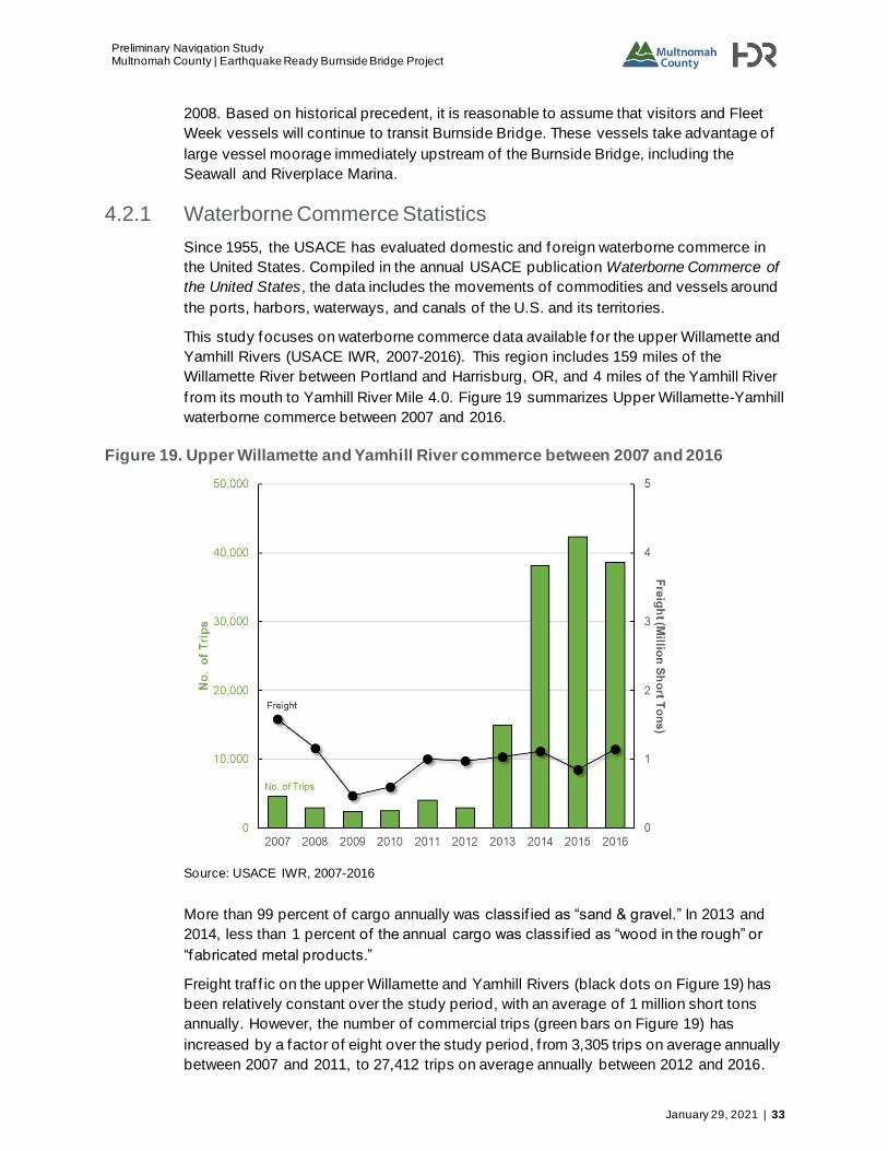
Preliminary Navigation Study
Multnomah County | Earthquake Ready Burnside Bridge Project
January 29, 2021 | 33
2008. Based on historical precedent, it is reasonable to assume that visitors and Fleet
Week vessels will continue to transit Burnside Bridge. These vessels take advantage of
large vessel moorage immediately upstream of the Burnside Bridge, including the
Seawall and Riverplace Marina.
4.2.1 Waterborne Commerce Statistics
Since 1955, the USACE has evaluated domestic and foreign waterborne commerce in
the United States. Compiled in the annual USACE publication Waterborne Commerce of
the United States, the data includes the movements of commodities and vessels around
the ports, harbors, waterways, and canals of the U.S. and its territories.
This study focuses on waterborne commerce data available for the upper Willamette and
Yamhill Rivers (USACE IWR, 2007-2016). This region includes 159 miles of the
Willamette River between Portland and Harrisburg, OR, and 4 miles of the Yamhill River
f rom its mouth to Yamhill River Mile 4.0. Figure 19 summarizes Upper Willamette-Yamhill
waterborne commerce between 2007 and 2016.
Figure 19. Upper Willamette and Yamhill River commerce between 2007 and 2016
Source: USACE IWR, 2007-2016
More than 99 percent of cargo annually was classif ied as “sand & gravel.” In 2013 and
2014, less than 1 percent of the annual cargo was classif ied as “wood in the rough” or
“fabricated metal products.”
Freight traf f ic on the upper Willamette and Yamhill Rivers (black dots on Figure 19) has
been relatively constant over the study period, with an average of 1 million short tons
annually. However, the number of commercial trips (green bars on Figure 19) has
increased by a factor of eight over the study period, f rom 3,305 trips on average annually
between 2007 and 2011, to 27,412 trips on average annually between 2012 and 2016.

Preliminary Navigation Study Multnomah County | Earthquake Ready Burnside Bridge Project
34 | January 29, 2021
The upward trend in trips suggests that although more commercial vessels are transiting
the upper Willamette and Yamhill Rivers in recent years, those vessels are carrying less
cargo. The increase in number of trips coincides with the departure of Hanjin Shipping
f rom Portland in early 2015 (Conley 2017).
4.3 Recreational Users
Approximately one-third of all river users are classif ied as recreational. These users
represent entities that transit the river for non-commercial and non-government
purposes, and includes sailing clubs, public moorages, private moorages, and a river
advocacy organization. Figure 20 depicts their air draf ts, expected elevation
requirements, beams, and horizontal clearance requirements.

Preliminary Navigation Study
Multnomah County | Earthquake Ready Burnside Bridge Project
January 29, 2021 | 35
Figure 20. Recreational users - Required Vertical Clearance Elevations (top) and Required Horizontal Clearance Widths (bottom)

Preliminary Navigation Study Multnomah County | Earthquake Ready Burnside Bridge Project
36 | January 29, 2021
At OHW, all recreational river users can safely transit beneath the inf inite and 167-foot
elevations of all bridge design states. Additionally, these users can safely transit the
horizontal clearances of all bridge design states.
4.4 Government Users
Less than one-tenth of all river users are classif ied as government. These users
represent state and federal agencies that transit the Willamette River for emergency
operations, defense activities, or channel maintenance. Figure 21 depicts their names,
air draf ts, and expected elevation requirements and horizontal clearance requirements.
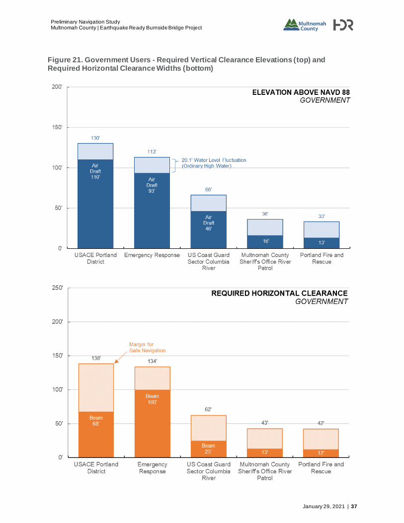
Preliminary Navigation Study
Multnomah County | Earthquake Ready Burnside Bridge Project
January 29, 2021 | 37
Figure 21. Government Users - Required Vertical Clearance Elevations (top) and Required Horizontal Clearance Widths (bottom)

Preliminary Navigation Study Multnomah County | Earthquake Ready Burnside Bridge Project
38 | January 29, 2021
At OHW, all government river users can safely transit beneath the inf inite and 167-foot
elevations of all bridge design states. Additionally, these users can safely transit the
horizontal clearances of all bridge design states.
Neither the temporary nor proposed bridge will impact USCG and other government
vessels’ ability to transit the bridge to conduct mission essential functions.
• U.S. Coast Guard Sector Columbia River monitors the river for search and rescue
purposes and patrols the river for major events such as dragon boat races.
Additionally, the 100-foot USCG Bluebell transits monthly to support Aids to
Navigation.
• Multnomah County Sheriff’s Office River Patrol patrols both the Columbia and
Willamette River as far as the county line near Oswego with vessels up to 36 feet in
length.
• Emergency Response Vessel represents the largest government river user. This
user is represented by a large derrick barge potentially called upon for the requisite
work. This particular derrick has an overall length of 333.5 feet with the boom
stowed, a beam of 100 feet, and an assumed maximum air draf t of 93 feet with the
spuds in the stowed position. More details are provided in Section 5.2.
In addition to the government river users above, the Columbia River Pilots are indirect
users of the Burnside Bridge. This state agency is comprised of expert vessel navigation
personnel (“pilots”) who board vessels upon request and navigate them safely in and out
of port.
Jeremy Nielsen, Vice President of the Columbia River Pilots, offered expertise regarding
clearances for this study. Compulsory pilotage jobs through the Burnside Bridge are
extremely rare, but voluntary pilot requests are typically made for Fleet Week vessels .
Captain Nielsen acknowledged that tug and barge traf f ic transits through the Burnside
Bridge are fairly light, but he cautioned against reducing the bridge’s horizontal
clearance. He reasoned that narrowing the approach to the Burnside Bridge would make
the approach to the Steel Bridge even more dif ficult.
4.5 Bridge Clearance Recommendations
4.5.1 Recommended Vertical Clearance Elevation
Figure 22 displays the elevation requirements of all known river users.
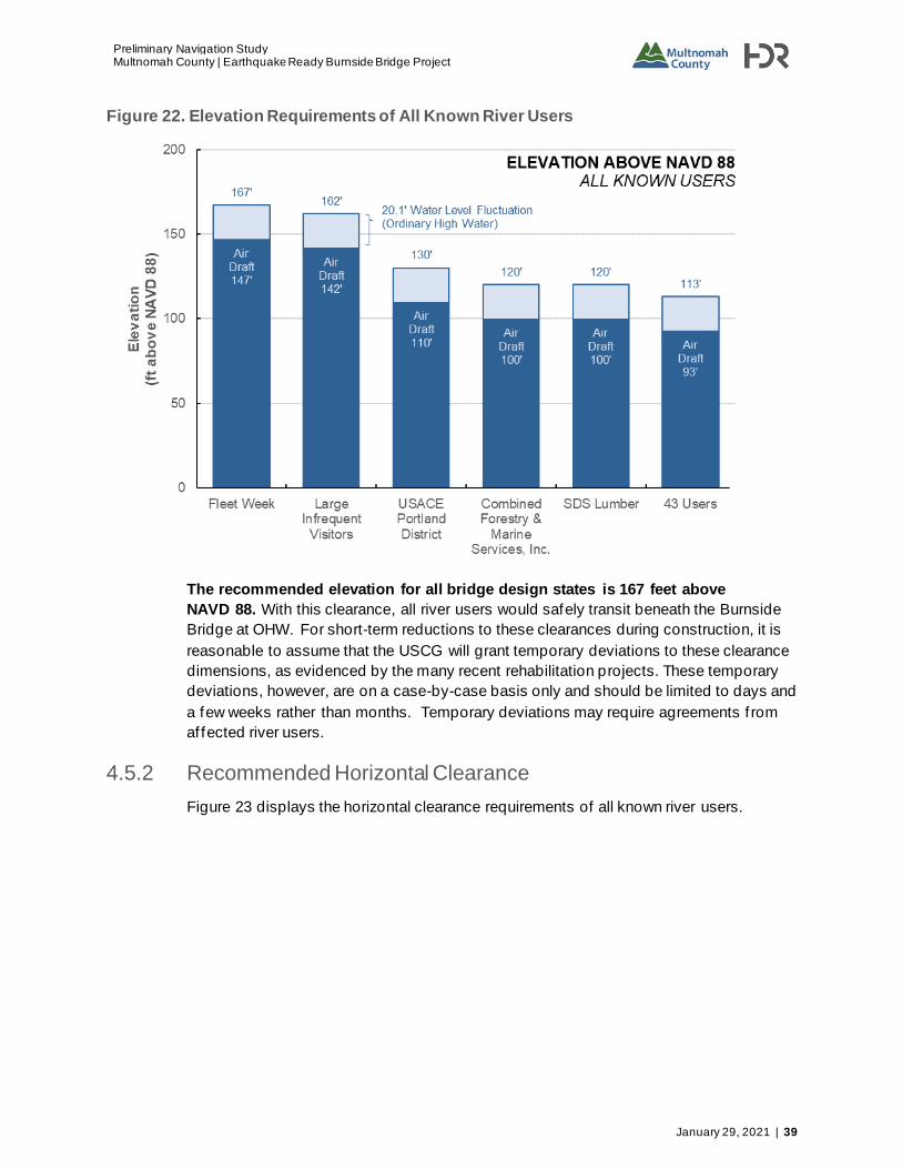
Preliminary Navigation Study
Multnomah County | Earthquake Ready Burnside Bridge Project
January 29, 2021 | 39
Figure 22. Elevation Requirements of All Known River Users
The recommended elevation for all bridge design states is 167 feet above
NAVD 88. With this clearance, all river users would safely transit beneath the Burnside
Bridge at OHW. For short-term reductions to these clearances during construction, it is
reasonable to assume that the USCG will grant temporary deviations to these clearance
dimensions, as evidenced by the many recent rehabilitation projects. These temporary
deviations, however, are on a case-by-case basis only and should be limited to days and
a few weeks rather than months. Temporary deviations may require agreements f rom
af fected river users.
4.5.2 Recommended Horizontal Clearance
Figure 23 displays the horizontal clearance requirements of all known river users.

Preliminary Navigation Study Multnomah County | Earthquake Ready Burnside Bridge Project
40 | January 29, 2021
Figure 23. Horizontal Clearance Requirements of All Known River Users
The recommended horizontal clearance needed to eliminate user impacts for all
bridge design states is 205 feet. Three bridge states satisfy this recommendation:
existing, permanent retrof it, and permanent replacement. The 165-foot horizontal
clearance of the temporary bridge state would impose an operations impact on three
known river users:
• Combined Forestry could not transit safely, but one or two tug assists could mitigate
the impact. However, tug assists would not guarantee safe transit for Combined
Forestry.
• AAC would require a tug assist for safe transit.
• Shaver Transportation would require a tug assist on a case-by-case basis.
Moreover, the Columbia River Pilots advised against narrowing the permanent Burnside
Bridge f rom its existing 205-foot horizontal clearance.
River User Consent for Single-Leaf Closure
Closure of a single leaf of the Burnside Bridge may occur during any bridge state for
bascule bridge designs. In this analysis, a single-leaf closure is assumed to cut available
horizontal clearance in half . Table 16 details assume single-leaf horizontal clearances
across all bridge states:

Preliminary Navigation Study
Multnomah County | Earthquake Ready Burnside Bridge Project
January 29, 2021 | 41
Table 16. Assumed Horizontal Clearance if a Single Leaf Must Be Closed
Design State (if Bascule) Horizontal Clearance Single-Leaf Horizontal
Clearance
Existing 205 ft. 102 ft.
Temporary 165 ft. 82 ft.
Permanent Retrofit 205 ft. 102 ft.
Permanent Replacement 205 ft. 102 ft.
USCG grants permission for single-leaf closures through Temporary Rules or Temporary
Deviations (Section 1.1). During a single-leaf closure, af fected river users include those
whose horizontal clearance requirements exceed the single-leaf horizontal clearance.
Applications for Temporary Rules and Temporary Deviations must indicate consent f rom
these af fected river users to forego transit during the closure period .
In the event of a single-leaf closure during any of the four Burnside Bridge states, the
following river users are recommended to be contacted and provide consent . All of the
following users have horizontal clearance requirements exceeding 82 feet:
• Combined Forestry & Marine Services, Inc.
• Shaver Transportation
• Advanced American Construction, Inc.
• Foss Maritime
• Portland Rose Festival Association (Fleet Week)
• Oregon Maritime Museum
• American Queen Steamboat Company
• HME Construction, Inc.
• Harley Marine Services; Olympic Tug & Barge; Pacif ic Terminals
• Marine Industrial Construction
• American Cruise Lines
• JT Marine, Inc.
• Ross Island Sand and Gravel
• Diversif ied Marine
• Lindblad Expeditions
• Tidewater Transportation and Terminals
• Portland Spirit
Horizontal clearance requirements and contact information for the above seventeen river
users are provided in Appendix A.

Preliminary Navigation Study Multnomah County | Earthquake Ready Burnside Bridge Project
42 | January 29, 2021
4.5.3 Clearance Window
Clearance windows illustrate the origin of the above recommended elevation and
horizontal clearance. Figure 24 displays the clearance windows for the vessels with the
largest clearances in each user type. The height and width of each box in Figure 24
correspond to the required elevation and horizontal clearance (centered on the
navigation channel) for each vessel.
Figure 24. Elevation Requirement and Corresponding Horizontal Clearance Requirement for Each River User Type
The 167-foot recommended elevation derives f rom the Fleet Week Vessels . The 205-foot
recommended horizontal clearance derives f rom both Combined Forestry tug and barge
vessels, as well as the Sternwheeler Portland for the Oregon Maritime Museum.
4.5.4 Navigation Impacts and Recommendations
River users provided feedback regarding navigating the existing Burnside Bridge. Their
concerns fell into several categories:
• Bridge proximity. The proximity of Burnside Bridge to neighboring bridges (Steel
Bridge, 0.4 miles downriver, and Morrison Bridge, 0.3 miles upriver) requires large
vessel operators to set their trajectory for a bridge two or three bridges away .
Horizontal clearance reductions complicate trajectory planning.
• River conditions. Eddies and boils near the bridge push vessels of f course. River
users with less power, such as recreational vessels and small vessel operators, have

Preliminary Navigation Study
Multnomah County | Earthquake Ready Burnside Bridge Project
January 29, 2021 | 43
less ability to overcome these conditions, and have more dif ficulty remaining within
restricted horizontal clearances.
• Congestion. Both commercial and recreational operators commented on the
dif f iculties of sharing the river with other traf f ic.
This feedback motivates recommendations for the design and construction of the
temporary and permanent bridges:
• Clear navigation signage for both commercial and recreational vessel operators.
• Dedicated transit lane for small recreational craf t such as kayaks and stand -up
paddleboards. The lane should be wide enough to allow the 35' long Portland Fire &
Rescue boat (33' elevation above NAVD 88) to turn around within the lane.
• Real-time clearance gauge. Bridge clearance signs of ten indicate clearance above a
f ixed datum. However, as river conditions change throughout the day, the river level
above the datum changes, and the vertical clearance f rom the water line to the
bridge changes as well. A real-time clearance gauge, such as the Microwave Air Gap
Bridge Clearance Sensor by NOAA, would make it easier for vessel operators to
know whether they clear the bridge at any given moment (Figure 25; NOAA 2005).
Figure 25. Air Gap Sensor on Gerald Desmond Bridge in Long Beach, California
NOAA Celebrates 200 Years of Science, Service, and Stewardship, n.d.

Preliminary Navigation Study Multnomah County | Earthquake Ready Burnside Bridge Project
44 | January 29, 2021
5 Earthquake Response Vessels
5.1 Overview
The following federal, state, and municipal agencies provided input regarding earthquake
response vessels that may have critical functions in the lower Willamette River following
a major earthquake:
• USCG Marine Transportation System Recovery Unit (MTSRU)
• Oregon Off ice of Emergency Management
• Multnomah County Of f ice of Emergency Management
• Portland Bureau of Emergency Management
• Port of Portland
FEMA Region 10 of fice was also contacted but declined to comment.
Depending on a variety of factors, the above agencies would likely coordinate
waterborne earthquake response in the Lower Willamette River. These agencies may
have overlapping jurisdictional claims and responsibilities . Because the Willamette River
constitutes “navigable waters of the United States” and part of the area marine
transportation system, USCG Incident Command (MTSRU) would likely be in a lead role,
at least initially.
5.2 Summary of Findings
There is no common def inition of emergency response vessels adopted by emergency
response agencies across varying levels of government locally or nationally, nor are
there identif ied standard vessel types for the requisite work functions of waterborne
earthquake response. However, there is largely consensus among the above agencies
on a four-phased approach to waterborne response and recovery of the af fected marine
transportation system, as described explicitly by key individuals of MTSRU. These
phases describe the necessary work functions of marine vessels following a significant
earthquake, f rom which suitable vessel types can be determined based on Glosten’s
experience and familiarity with the commercial marine industry .
5.2.1 Initial Response
Initial Response is focused on the immediate rescue and/or movement of people to
safety. This can take the form of search and rescue (SAR) operations, mass
evacuations, or both, depending on the nature and severity of circumstances or hazards .
While this phase of response is focused on lifesaving, it also includes preliminary, non-
technical assessments of damage and/or impacts that can be viewed f rom a waterway
vantage, which may conf irm or deny coinciding emerging land/air assessments . These
non-technical assessments are largely directed at critical components of the marine
transportation system and assist in identifying and mobilizing appropriate technical
assessment resources.
Suitable vessel types for this work would likely include:

Preliminary Navigation Study
Multnomah County | Earthquake Ready Burnside Bridge Project
January 29, 2021 | 45
• Smaller shallow-draf t SAR vessels or other fast craf t - perhaps with f iref ighting and
EMS capabilities. Landing craf t may prove necessary for nearshore rescues where
conventional docking of vessels may not be possible.
• “Vessels of opportunity” for mass evacuation, such as: existing passenger vessels
(perhaps modif ied to expedite berthing and/or loading and offloading processes);
scows and/or f lat-deck barges handled by a tug or tug(s); landing craf t, or; other
vessel types suitable for carriage of passengers on an emergency basis.
• Purpose-built vessels for mass evacuation – i.e. shallow-draf t passenger-only
vessels with the ability to berth at multiple locations and make rapid ship-to-shore
transfers. Landing craf t designs could prove particularly ef fective for this purpose.
Such vessel types are similar in size to those currently transiting the Lower Willamette
River on a regular basis, and therefore would not drive special consideration with respect
to elevation or horizontal clearances of the replacement Burnside Bridge.
Phase I: Stabilization
The stabilization phase bridges the response between the Initial Response and
Sustainment phases. Importantly, stabilization occurs even as the immediate response
continues. In this phase, non-technical assessments begin supporting partial waterway
restoration. These solutions may provide a limited use of some part of the waterway
inf rastructure via a waiver or prescribed limitations. This may support ongoing lifesaving
operations as well as emerging community life sustainment priorities and decision
making. The Stabilization phase maintains the forward progress of response, matching a
need for cohesive and logical decisions to be made concerning most critical actions
necessary to complete quick f ixes even as more long-term recovery resources can be
brought to bear to address critical regional sustainment needs.
Suitable vessel types for this work are the same as those listed for the Initial Response
phase and would not drive special consideration with respect to elevation or horizontal
clearances of the replacement Burnside Bridge.
Phase II: Sustainment
This stage of the response ef fort involves the evaluation and technical/engineering
assessment of critical inf rastructure associated with af fected waterways, including, but
not limited to: marine terminals and other port inf rastructure, public waterf ronts,
pedestrian and vehicular bridges, power line crossings, and cable and utility crossings.
Onsite vessel support is necessary to provide access to affected sites and to assess the
condition and/or integrity of supporting structures. For this reason, vessels associated
with this stage of the response ef fort may need the capab ility to support commercial dive
operations or ROV operations for conducting underwater surveys.
Suitable vessel types for this work would likely include small (approximately 100 feet or
less) nearshore survey vessels of shallow draf t. These vessels may have the ability to
support commercial dive operations and/or deploy and recover underwater survey
equipment. The vessels may also require specialized sonar equipment for the location
and evaluation of sub-sea structures, and to conduct or otherwise support bathymetric
surveys.

Preliminary Navigation Study Multnomah County | Earthquake Ready Burnside Bridge Project
46 | January 29, 2021
Such vessel types are similar in size to those currently transiting the Lower Willamette
River on a regular basis, and therefore would not drive special consideration with respect
to elevation or horizontal clearances of the replacement Burnside Bridge.
Following the technical assessments described above, USCG and other agencies (local,
state, or federal) may, depending on the nature of the af fected inf rastructure and
jurisdictional issues, support evaluation of community impacts caused by earthquake-
damaged inf rastructure or the condition of the waterway. Following this evaluation,
strategic decisions will be made as to the nature and sequencing of removal and
remediation work. The scope of this work will strongly inf luence vessel requirements for
the f inal phase of the response, Long-term Recovery/Restoration.
Phase III: Long-term Recovery/Restoration
The Long-term Recovery/Restoration phase encompasses the remedial actions
necessary to restore full function of the waterway and associated inf rastructure. This is
the time priorities must be established and work commenced to begin to remove the
previously established Stabilization and Sustainment “workarounds” in such a way as to
keep the community functioning as critical infrastructure is restored to a state that meets
all existing and/or new regulations or requirements. More specif ically, the Long-term
Recovery/Restoration phase includes the requisite construction and/or marine
construction work for the removal of hazards and rebuilding o f key inf rastructure, as
identif ied during the Sustainment phase.
Depending on the scope of the construction work, suitable vessel types for this purpose
would likely include:
• A variety of barges commonly used to support marine construction projects, including
but not limited to:
o Derrick barges, equipped to support pile-driving and removal operations (i.e.
f loating cranes)
o Flat-deck barges (with or without spuds) with a variety of materials and heavy
equipment on deck, including cranes and/or dredging equipment
o Purpose-built marine dredging vessels
o Scows and/or dump barges
• Harbor tugs of relatively shallow draf t, capable of handling the above barge types in
conf ined waterways
• Work skif fs
Some of these vessel types may be considerably larger than those currently transiting or
operating in the Lower Willamette River (derrick and spud barges in particular) and
therefore should drive special consideration of elevation and horizontal clearances of the
replacement Burnside Bridge.
Figure 26 shows a representative large derrick barge which could be called upon for the
requisite work. This particular derrick has an overall length of 333.5 feet with the boom
stowed, a beam of 100 feet, and an assumed maximum air draf t of 93 feet with the spuds
stowed.

Preliminary Navigation Study
Multnomah County | Earthquake Ready Burnside Bridge Project
January 29, 2021 | 47
Figure 26. Representative Derrick Barge
Though larger derricks do exist on the U.S. West Coast, we estimate this vessel
represents a “largest vessel type” mob ilized for removal and remediation work in the
Lower Willamette River and, therefore, is conservative for determining reasonable
elevation and horizontal clearances for the replacement Burnside Bridge. This vessel is
incorporated into the analysis of government river users (Section 4.4).
Additionally, the spud height of this derrick, which is the most plausible limiting dimension
for bridge transits, is equal to or greater than the majority of derrick barges in service on
the U.S. West Coast. Taller spuds would not be necessary for construction work in the
Lower Willamette River, given that maximum water depths are less than 80 feet.
5.2.2 Considerations of Deep Draft Vessels
Following a worst-case Cascadia Subduction Zone earthquake, it is conceivable that one
or more local area hospitals may be severely damaged or otherwise unusable for
treatment of patients. In such circumstances, an emergency ‘hospital ship’ may have to
be mobilized to serve the medical needs of the community temporarily, until local area
hospitals can be brought back online. This need would most likely be met by a U.S. naval
vessel, which have deep operating draf ts and high superstructures, as compared to the
current marine traf f ic.
Assuming such vessels would enter the Lower Willamette River following an earthquake,
they would obviously drive special consideration of elevations for the replacement
Burnside Bridge. However, limited water depth and the presence (or uncertainty) of
navigational hazards would likely preclude such vessels f rom entering the waterway .

Preliminary Navigation Study Multnomah County | Earthquake Ready Burnside Bridge Project
48 | January 29, 2021
No Federal Navigation Channel is currently maintained on the Willamette River. The river
gradually shallows upriver, which restricts the movement of deep draf t vessels .
Additionally, it is possible that one or more of the bridges downstream of the Burnsid e
Bridge could collapse during a major earthquake – in whole or in part - leaving fallen
bridge structure in the water, possibly obstructing the navigable channel. For these
reasons, and, based on input f rom current and former USCG of f icers at the above
agencies, it is assumed that any U.S. naval vessel acting as a temporary hospital ship
would serve the local community by anchoring in the Columbia River, just outside the
mouth of the Willamette River, to minimize navigational risk.
It is therefore our recommendation that U.S. naval vessels or other deep draf t vessels
not be considered in determining minimum elevation and horizontal clearances for the
new Burnside Bridge.
6 Conclusions and Recommendations
6.1 Minimum Recommended Elevation
The minimum recommended elevation for all bridge design states is 167 feet
above NAVD 88. At OHW, all river users can safely transit beneath the 167-foot
elevation of the temporary and proposed bridge design states.
6.2 Minimum Recommended Horizontal Clearance
The minimum recommended horizontal clearance for all bridge design states is
205 feet. Three bridge design states satisfy this recommendation: existing, permanent
retrof it, and permanent replacement. The 165-foot horizontal clearance of the temporary
bridge design state would impose an operations impact on three known river users:
• Combined Forestry could not transit safely, but one or two tug assists could mitigate
the impact. However, tug assists would not guarantee safe transit for Combined
Forestry.
• AAC would require a tug assist for safe transit.
• Shaver Transportation would require a tug assist on a case-by-case basis.
Moreover, the Columbia River Pilots advised against narrowing the Burnside Bridge. The
Burnside Bridge is the narrowest bridge in the Sellwood Reach.
The temporary bridge would become the most restrictive horizontal clearance on the
waterway. Any reduction to its horizontal clearance at either the temporary or permanent
phases will require negotiation with these impacted river users.
6.3 Bridge Width
Bridge upriver/downriver width (Figure 1) also has navigation impacts. The width of the
temporary bridge system could range f rom 220 feet to 390 feet. Some river users will
require a tug assist due to this extensive bridge width. The width of the permanent
replacement bridge could range f rom 150 feet to 195 feet. River users do not anticipate
requiring regular tug assists to navigate this bridge width. Depending on future project

Preliminary Navigation Study
Multnomah County | Earthquake Ready Burnside Bridge Project
January 29, 2021 | 49
work and river conditions, occasional tug assist may be needed. One river user
recommended widening the horizontal clearance to aid navigation through the longer
bridge corridor.
6.4 Impact of Clearance Requirements on Bridge Design
States
No changes to any design states would be needed to satisfy the minimum recommended
elevation. All bridge design states meet or exceed the minimum recommended elevation
of 167 feet.
No changes to the existing, permanent retrof it, or permanent replacement bridge design
states would be needed to satisfy the minimum recommended horizontal clearance. All
bridge design states meet or exceed the minimum horizontal clearance of 205 feet.
The temporary bridge design state does not meet the minimum recommended
horizontal clearance of 205 feet. Providing a tug assist for the temporary bridge
mitigates, but may not fully eliminate, the impact on river user operations; one user
anticipates an operational impact even if assist tugs were provided .
Design and Construction Recommendations
Based on feedback f rom participating river users and elevation and horizontal clearance
requirements, several recommendations are presented for the design and construction of
all bridge states:
• Clear navigation signage for both commercial and recreational vessel operators.
• Dedicated transit lane for small recreational craf t such as kayaks and stand-up
paddleboards.
• Real-time vertical clearance gauge to inform operators whether they clear the bridge
at any given moment or river level.

Preliminary Navigation Study Multnomah County | Earthquake Ready Burnside Bridge Project
50 | January 29, 2021
7 References
City of Portland, Oregon, Bureau of Planning and Sustainability (BPS)
1987 Willamette Greenway Plan. https://www.portlandoregon.gov/bps/article/59067
2001 River Renaissance Vision: January 2001 https://www.portlandoregon.gov/bps/article/86273
2004 River Renaissance Strategy: December 2004. https://www.portlandoregon.gov/bps/article/86274
2006 The River Plan Concept (Endorsed April 26, 2006). https://www.portlandoregon.gov/bps/article/120298
2017 Central City 2035: CC2035 Recommended Draf t. https://www.portlandoregon.gov/bps/article/564038
2020 Proposed Draf t: River Plan / South Reach
https://beta.portland.gov/bps/south-reach/river-plan-south-reach-project-documents
n.d. Planning and Sustainability. River Plan. Accessed March 18, 2019. https://www.portlandoregon.gov/bps/42540
Conley, Casey
2017 “Foss Maritime hybrid f inds new home where grain is king,” Professional Mariner, Issue #211, April 2017. Page 15-19
https://issuu.com/navigatorpublishing/docs/pm211_april17_digitial_edition
Cruisemapper
n.d. Ships. ms The World. Access May 8, 2019. https://www.cruisemapper.com/ships/ms-The-World-1119
Federal Emergency Management Agency (FEMA)
2010 Flood Insurance Study: City of Portland, Oregon (Number 410183V000B). Revised 26 November 2010. https://www.portlandoregon.gov/bds/article/464881
Google Earth
n.d. Burnside Bridge, Portland, Oregon. Accessed July 24, 2019. https://www.google.com/maps/@45.52305,-122.66755,1979m/data=!3m1!1e3
Multnomah County
n.d. Earthquake Ready Burnside Bridge. Accessed 22 May 22, 2019. https://multco.us/earthquake-ready-burnside-bridge
National Oceanic and Atmospheric Administration (NOAA)
2005 Microwave Air Gap-Bridge Clearance Sensor Test, Evaluation, and Implementation Report, NOAA Technical Report NOS CO-OPS 042. https://tidesandcurrents.noaa.gov/publications/tecrpt42.pdf
n.d. Columbia River Estuary Forecast System (CREOFS), Tides & Currents. Accessed March 13, 2019. https://tidesandcurrents.noaa.gov/ofs/creofs/creofs_info.html
n.d. NOAA Celebrates 200 Years of Science, Service, and Stewardship. Accessed May 22, 2019. https://celebrating200years.noaa.gov/transformations/tides/image7.html
n.d. Portland Morrison Street Bridge, OR – Station ID: 9439221, Accessed March 11, 2019. https://tidesandcurrents.noaa.gov/stationhome.html?id=9439221

Preliminary Navigation Study
Multnomah County | Earthquake Ready Burnside Bridge Project
January 29, 2021 | 51
n.d. Vertical Datums, National Geodetic Survey: Positioning America for the Future. Accessed March 13, 2019. https://www.ngs.noaa.gov/datums/vertical/index.shtml
Oregon Department of Land Conservation and Development
2010 Oregon’s Statewide Planning Goals & Guidelines. https://www.oregon.gov/lcd/OP/Documents/compilation_of_statewide_planning_goals.pdf
Pacif ic Northwest Ecosystem Research Consortium (PNERC)
2002 Willamette River Basin Atlas: Trajectories of Environmental and Ecological Change http://www.fsl.orst.edu/pnwerc/wrb/Atlas_web_compressed/PDFtoc.html
U.S. Army Corps of Engineers (USACE)
2018 Def inition of Navigable Waters of the United States. 33 Code of Federal Regulations 329.4. https://www.govinfo.gov/content/pkg/CFR-2018-title33-vol3/xml/CFR-2018-title33-
vol3-part329.xml
2019 Navigation and Navigable Waters. 33 Code of Federal Regulations 114-116 https://www.govinfo.gov/content/pkg/CFR-2012-title33-vol1/pdf/CFR-2012-title33-vol1-
chapI.pdf
2019 Navigation and Navigable Waters. 33 Code of Federal Regulations 162-163. https://ecfr.io/Title-33/pt33.2.162, https://ecfr.io/Title-33/pt33.2.163#se33.2.163_101
U.S. Army Corps of Engineers (USACE), Institute for Water Resources
n.d. Waterborne Commerce of the United States, Calendar Years 2007 – 2016 (IWR-WCUS-04-4 through IWR-WCUS-16-4).
U.S. Army Corps of Engineers (USACE), Portland District
2003 Columbia River Channel Improvement Project: Final Supplemental Integrated Feasibility Report and Environmental Impact Statement.
2017 Willamette Basin Review Feasibility Study: (DRAFT) Integrated Feasibility Report and Environmental Assessment.
n.d. Building Strong® at the Columbia and Lower Willamette Rivers Project . Accessed March 6, 2019. https://www.nwp.usace.army.mil/Missions/Navigation/Channels/Columbia-L-
Willamette/
U.S. Coast Guard (USCG)
2016 Off ice of Bridge Programs Bridge Permit Application Guide OMB Control Number 1625-0015, COMDTPUB P16591.3D https://www.dco.uscg.mil/Portals/9/DCO%20Documents/5pw/Office%20of%20Bridge%20Programs/BPAG%20COMDTPUB%20P16591%203D_Sequential%20Clearance%20Final(July2016).pdf
n.d. Guide Clearances. Accessed March 13, 2019. https://www.dco.uscg.mil/Our-Organization/Assistant-Commandant-for-Prevention-Policy-CG-5P/Marine-Transportation-Systems-CG-5PW/Off ice-of-Bridge-Programs/Bridge-Guide-Clearances/
U.S. Geological Survey (USGS)
n.d. USGS 14211720 Willamette River at Portland, OR. Accessed March 11, 2019. https://waterdata.usgs.gov/nwis/inventory?agency_code=USGS&site_no=14211720
n.d. USGS 14207770 Willamette River Below Falls, at Oregon City, OR. Accessed March 11, 2019. https://waterdata.usgs.gov/nwis/inventory?agency_code=USGS&site_no=14207770


Preliminary Navigation Study
Multnomah County | Earthquake Ready Burnside Bridge Project
January 29, 2021 | A-1
Appendix A. River User Master List


Preliminary Navigation Study
Multnomah County | Earthquake Ready Burnside Bridge Project
January 29, 2021 | A-1
River Users Sorted by Air Draft
User Type Contact Phone Email LOA Air Draft
Horizontal Clearance
Fleet Week Commercial - Other
Steven Bledsoe (Waterf ront Activities Manager)
503.227.2681 stevenb@ rosefestival.org
443.0 147.0 158.9
Large Inf requent Visitors
Commercial - Other
Sean Whalen (cc on correspondence)
503.209.8109 (Whalen cell)
sean.whalen@ portlandoregon.gov
644.0 142.0 150.0
USACE Portland District Govt. - Inf rastructure
Karla Ellis 503.808.4377 karla.g.ellis@ usace.army.mil
350.0 110.0 138.2
Combined Forestry & Marine Services, Inc.
Commercial - Tug/Barge
Clark Vincent Caffall (President)
360.921.4304 (cell) 360.225.8359 (house)
- - 100.0 205.0
SDS Lumber Commercial - Tug/Barge
Captain Gary Collins (Marine Supervisor)
509.493.2155 (of fice) 541.490.1370 (cell)
- 55.0 100.0 52.0
Emergency Response Govt. - Inf rastructure
Mr. Scott Bates (Seattle); Mr. Bynum (San Francisco)
206.220.7231 (Bates, Seattle) 415.399.7364 (Bynum, SF)
- 300.0 93.0 133.5
HME Construction, Inc. Commercial - Tug/Barge
Greg Speyer (Vice President of Administration)
360.695.4553 greg.speyer@ hmeconst.com
- 90.0 150.0
KFS Boat Docks Commercial - Tug/Barge
Eric Dye 503.449.6667 kfsdocks@ comcast.net
100.0 90.0 68.0
Schooner Creek Boat Works
Recreational Pascal (General Manager) 503.735.0569 generalmanager@ schoonercreek.com
110.0 90.0 70.6
Sportcraft Landing Moorage
Recreational Kimberly Dye 503.655.0981 (of fice) 503.780.6667 (cell?)
kimberlydyerealtor@ comcast.net
100.0 90.0 68.0
Portland Yacht Club Recreational Kathleen Inman (Member Service Coordinator)
503.285.1922 admin@ portlandyc.com
65.0 87.0 51.5
JT Marine Inc Commercial - Tug/Barge
Irene Toristoja (Controller) 360.750.1300 irene@ jtmarineinc.com
- 85.0 123.0

Preliminary Navigation Study Multnomah County | Earthquake Ready Burnside Bridge Project
A-2 | January 29, 2021
River Users Sorted by Air Draft
User Type Contact Phone Email LOA Air Draft
Horizontal Clearance
Portland Spirit Commercial - Cruise
Daniel Yates (President) Captain Cameron Hunt
503.224.3900 (Yates) 360.305.2379 (Hunt)
dan@ portlandspirit.com
- 77.5 97.0
Larson's Moorage Commercial - Tug/Barge
Ken Larson (Owner) 503.286.1233 - - 70.0 50.0
Foothills Park Recreational Ben Labounty (Park Ranger)
503.675.2548 blabounty@ ci.oswego.us
40.0 68.1 44.1
Sail PDX (Oregon Corinthian Sailing Association, OCSA)
Recreational Bruce Newton (Commodore)
503.806.6625 commodore@ SailOCSA.org
46.8 68.1 45.8
Sternwheeler Portland Commercial - Cruise
Brad (President) 503.224.7724 president@ oregonmaritime museum.org
219.0 68.0 205.0
Promise Charters - Sailboat Promise
Commercial - Cruise
Captain Warren Brown 503.621.2561 captain@ sailpromise.com
- 68.0 -
Diversified Marine Commercial - Tug/Barge
Kurt Redd (CEO) 503.289.2669 kredd@ teleport.com
- 65.0 105.0
Ross Island Sand and Gravel (RISG)
Commercial - Tug/Barge
Craig Jacobs (General Manager, Sand, Gravel, and Crushed Stone Operations)
503.239.5504 - - 65.0 120.0
Sailboat Prospect Commercial - Cruise
Lavine A. Linker - - - 65.0 -
Foss Maritime (Columbia / Snake River Of f ice)
Commercial - Tug/Barge
Captain Peter Roney (Project Cargo Transp, West Coast) Captain Toby Jacobsen (Port Captain)
360.391.4486 (Roney) 503.286.0631 (Jacobsen; Press 4 for Operations Dept., then 1 for Port Captain)
proney@ foss.com
- 64.0 165.0
Harley Marine Services, Olympic Tug & Barge, Pacif ic Terminals
Commercial - Tug/Barge
Kirk 503.737.0124 - - 60.0 150.0

Preliminary Navigation Study
Multnomah County | Earthquake Ready Burnside Bridge Project
January 29, 2021 | A-3
River Users Sorted by Air Draft
User Type Contact Phone Email LOA Air Draft
Horizontal Clearance
Marine Industrial Construction
Commercial - Tug/Barge
Tom McCauley 503.682.9925 tom@ marineindust.com
250.0 60.0 138.0
McCuddy's Marina, McCuddy's Landing, Big Oak Marina, Hayden Island Moorage, Marine Drive Moorage
Recreational Mark McCuddy 503.289.7879 Mark@ McCuddysMarina .com
- 60.0 20.0
Shaver Transportation Commercial - Tug/Barge
Fred Harding or Brad Korpela (Port Captains)
503.228.8850 pc@ shaver transportation.com
110.0 58.0 200.0
Advanced American Construction, Inc.
Commercial - Tug/Barge
Evan Clemson 503.445.9000 evanc@ callaac.com
- 55.0 185.0
American Cruise Lines Commercial - Cruise
Media and Public Relations
203.453.6800 media@ americancruise lines.com
335.0 55.0 131.2
Lindblad Expeditions Commercial - Cruise
Captain Mike Jones (Vice President of Fleet Support)
206.403.1512 mikej@ expeditions.com
238.0 52.0 104.0
Scovare Expeditions Inc.
Commercial - Cruise
Captain Shane St. Clair 503.893.2283 (of fice) 971.219.5797 (cell)
info@ sailscovare.com
- 52.0 25.0
Tidewater Transportation and Terminals
Commercial - Tug/Barge
Neil Maunu (Business Development)
360.759.0321 (direct) 503.536.3760 (mobile)
neil@ tidewater.com
- 52.0 100.0
UnCruise Adventures Commercial - Cruise
JD Ross Leahy (Director of Nautical Operations)
206.284.0300 - - 52.0 70.0
Small Yacht Sailing Club of Oregon (SYSCO)
Recreational Anna Campagna (Commodore)
503.789.0586 commodore@ syscosailing.org
65.0 50.0 52.0
US Coast Guard Sector Columbia River
Govt - Regulatory Russell Nichols (Waterways Management)
503.240.2575 - 100.0 46.0 62.2

Preliminary Navigation Study Multnomah County | Earthquake Ready Burnside Bridge Project
A-4 | January 29, 2021
River Users Sorted by Air Draft
User Type Contact Phone Email LOA Air Draft
Horizontal Clearance
Oregon Women's Sailing Association
Recreational Tressa Yellig (Rear Commodore)
503.451.0061 rearcommodore@ owsa.net
29.9 44.0 40.5
Fred Devine Diving and Salvage Co.
Commercial - Tug/Barge
Marvin Smith (Operations Manager)
503.283.5285 devinesalv@ msn.com
- 36.0 36.0
Oregon Yacht Club Recreational Cathryn Cushing (Secretary)
503.804.9171 cath5155@ hotmail.com
35.0 35.0 42.7
Waverly Marina Recreational Andrew (Harbormaster) (503) 231-3985 Harbormaster andrew@ comcast.net
35.0 35.0 42.7
Willamette Queen Commercial - Cruise
Barbara Chesbrough 503.371.1103 WQSternwheeler@ aol.com
- 28.0 44.0
Willamette Sailing Club Recreational Brandon Roberts (Club Manager)
503.246.5345 manager@ willamettesailing club.com
- 25.0 32.1
Tyee Yacht Club Recreational Rick Bryant (2019 Commodore)
503.284.4772 (club) 503.329.4125 (cell)
pdxh20man@ gmail.com
55.0 23.0 36.0
Anchorage Launch Commercial - Cruise
Alex 503.246.0535 - - 20.0 30.0
Columbia River Launch Service
Commercial - Cruise
Klancy Shriver 360.703.7721 (of fice); 360.430.7253 (direct)
klancy@ crlsllc.net
40.0 20.0 43.1
Portland Fire & Rescue Govt Sean Whalen 503.209.8109 (Whalen cell)
sean.whalen@ portlandoregon.gov
35.0 13.0 42.2
Multnomah County Sherif f's Office River Patrol
Govt - Traf fic Deputy Rod Nuzum 503.988.6788 Rod.nuzum@ mcso.us
36.0 16.0 42.7
Willamette Riverkeeper Recreational Kate Kuthe 503.223.6418 kate@ willametteriver keeper.org
- 3.0 3.0
American Queen Steamboat Company
Commercial - Cruise
- - - 380.0 - 153.0

Preliminary Navigation Study
Multnomah County | Earthquake Ready Burnside Bridge Project
January 29, 2021 | A-5
River Users Sorted by Air Draft
User Type Contact Phone Email LOA Air Draft
Horizontal Clearance
Brusco Tug & Barge Commercial - Tug/Barge
Dan Zandell 360.636.3341 (of fice) 360.562.6876 (cell)
dan.zandell@ bruscotug.com
- - -
River Users Sorted by Horizontal Clearance
User Type Contact Phone Email LOA Air Draft
Horizontal Clearance
Combined Forestry & Marine Services, Inc.
Commercial - Tug/Barge
Clark Vincent Caffall (President)
360.921.4304 (cell) 360.225.8359 (house)
- - 100.0 205.0
Sternwheeler Portland Commercial - Cruise
Brad (President) 503.224.7724 president@ oregonmaritime museum.org
219.0 68.0 205
Shaver Transportation Commercial - Tug/Barge
Fred Harding or Brad Korpela (Port Captains)
503.228.8850 pc@ shaver transportation.com
110.0 58.0 200.0
Advanced American Construction, Inc.
Commercial - Tug/Barge
Evan Clemson 503.445.9000 evanc@ callaac.com
- 55.0 185.0
Foss Maritime (Columbia / Snake River Of f ice)
Commercial - Tug/Barge
Captain Peter Roney (Project Cargo Transp, West Coast) Captain Toby Jacobsen (Port Captain)
360.391.4486 (Roney) 503.286.0631 (Jacobsen; Press 4 for Operations Dept, then 1 for Port Captain)
proney@ foss.com
- 64.0 165.0
Fleet Week Commercial - Other
Steven Bledsoe (Waterf ront Activities Manager)
503.227.2681 stevenb@ rosefestival.org
443.0 147.0 158.9
American Queen Steamboat Company
Commercial - Cruise
- - - 380.0 - 153.0
Harley Marine Services, Olympic Tug & Barge, Pacif ic Terminals
Commercial - Tug/Barge
Kirk 503.737.0124 - - 60.0 150.0

Preliminary Navigation Study Multnomah County | Earthquake Ready Burnside Bridge Project
A-6 | January 29, 2021
River Users Sorted by Horizontal Clearance
User Type Contact Phone Email LOA Air Draft
Horizontal Clearance
HME Construction, Inc. Commercial - Tug/Barge
Greg Speyer (Vice President of Administration)
360.695.4553 greg.speyer@ hmeconst.com
- 90.0 150.0
Large Inf requent Visitors
Commercial - Other
Sean Whalen (cc on correspondence)
503.209.8109 (Whalen cell)
sean.whalen@ portlandoregon.gov
644.0 142.0 150.0
USACE Portland District Govt. - Inf rastructure
Karla Ellis 503.808.4377 karla.g.ellis@ usace.army.mil
350.0 110.0 138.2
Marine Industrial Construction
Commercial - Tug/Barge
Tom McCauley 503.682.9925 tom@ marineindust.com
250.0 60.0 138.0
Emergency Response Govt - Inf rastructure
Mr Scott Bates (Seattle); Mr. Bynum (San Francisco)
206.220.7231 (Bates, Seattle) 415.399.7364 (Bynum, SF)
- 300.0 93.0 133.5
American Cruise Lines Commercial - Cruise
Media and Public Relations
203.453.6800 media@ americancruise lines.com
335.0 55.0 131.2
JT Marine Inc Commercial - Tug/Barge
Irene Toristoja (Controller)
360.750.1300 irene@ jtmarineinc.com
- 85.0 123.0
Ross Island Sand and Gravel (RISG)
Commercial - Tug/Barge
Craig Jacobs (General Manager, Sand, Gravel, and Crushed Stone Operations)
503.239.5504 - - 65.0 120.0
Diversified Marine Commercial - Tug/Barge
Kurt Redd (CEO) 503.289.2669 kredd@ teleport.com
- 65.0 105.0
Lindblad Expeditions Commercial - Cruise
Captain Mike Jones (Vice President of Fleet Support)
206.403.1512 mikej@ expeditions.com
238.0 52.0 104.0
Tidewater Transportation and Terminals
Commercial - Tug/Barge
Neil Maunu (Business Development)
360.759.0321 (direct) 503.536.3760 (mobile)
neil@ tidewater.com
- 52.0 100.0
Portland Spirit Commercial - Cruise
Daniel Yates (President) Captain Cameron Hunt
503.224.3900 (Yates) 360.305.2379 (Hunt)
dan@ portlandspirit.com
- 77.5 97.0
Schooner Creek Boat Works
Recreational Pascal (General Manager)
503.735.0569 generalmanager@ schoonercreek.com
110.0 90.0 70.6

Preliminary Navigation Study
Multnomah County | Earthquake Ready Burnside Bridge Project
January 29, 2021 | A-7
River Users Sorted by Horizontal Clearance
User Type Contact Phone Email LOA Air Draft
Horizontal Clearance
UnCruise Adventures Commercial - Cruise
JD Ross Leahy (Director of Nautical Operations)
206.284.0300 - - 52.0 70.0
KFS Boat Docks Commercial - Tug/Barge
Eric Dye 503.449.6667 kfsdocks@ comcast.net
100.0 90.0 68.0
Sportcraft Landing Moorage
Recreational Kimberly Dye 503.655.0981 (office) 503.780.6667 (cell?)
kimberlydyerealtor@ comcast.net
100.0 90.0 68.0
US Coast Guard Sector Columbia River
Govt - Regulatory
Russell Nichols (Waterways Management)
503.240.2575 - 100.0 46.0 62.2
SDS Lumber Commercial - Tug/Barge
Captain Gary Collins (Marine Supervisor)
509.493.2155 (office) 541.490.1370 (cell)
- 55.0 100.0 52.0
Small Yacht Sailing Club of Oregon (SYSCO)
Recreational Anna Campagna (Commodore)
503.789.0586 commodore@ syscosailing.org
65.0 50.0 52.0
Portland Yacht Club Recreational Kathleen Inman (Member Service Coordinator)
503.285.1922 admin@ portlandyc.com
65.0 87.0 51.5
Larson's Moorage Commercial - Tug/Barge
Ken Larson (Owner) 503.286.1233 - - 70.0 50.0
Sail PDX (Oregon Corinthian Sailing Association, OCSA)
Recreational Bruce Newton (Commodore)
503.806.6625 commodore@ SailOCSA.org
46.8 68.1 45.8
Foothills Park Recreational Ben Labounty (Park Ranger)
503.675.2548 blabounty@ ci.oswego.us
40.0 68.1 44.1
Willamette Queen Commercial - Cruise
Barbara Chesbrough 503.371.1103 WQSternwheeler@ aol.com
- 28.0 44.0
Columbia River Launch Service
Commercial - Cruise
Klancy Shriver 360.703.7721 (office); 360.430.7253 (direct)
klancy@ crlsllc.net
40.0 20.0 43.1
Multnomah County Sherif f's Office River Patrol
Govt. - Traf fic Deputy Rod Nuzum 503.988.6788 Rod.nuzum@ mcso.us
36.0 16.0 42.7
Oregon Yacht Club Recreational Cathryn Cushing (Secretary)
503.804.9171 cath5155@ hotmail.com
35.0 35.0 42.7

Preliminary Navigation Study Multnomah County | Earthquake Ready Burnside Bridge Project
A-8 | January 29, 2021
River Users Sorted by Horizontal Clearance
User Type Contact Phone Email LOA Air Draft
Horizontal Clearance
Waverly Marina Recreational Andrew (Harbormaster) (503) 231-3985 Harbormaster andrew@ comcast.net
35.0 35.0 42.7
Portland Fire & Rescue Govt Sean Whalen 503.209.8109 (Whalen cell)
sean.whalen@ portlandoregon.gov
35.0 13.0 42.2
Oregon Women's Sailing Association
Recreational Tressa Yellig (Rear Commodore)
503.451.0061 rearcommodore@ owsa.net
29.9 44.0 40.5
Fred Devine Diving and Salvage Co.
Commercial - Tug/Barge
Marvin Smith (Operations Manager)
503.283.5285 devinesalv@ msn.com
- 36.0 36.0
Tyee Yacht Club Recreational Rick Bryant (2019 Commodore)
503.284.4772 (club) 503.329.4125 (cell)
pdxh20man@ gmail.com
55.0 23.0 36.0
Willamette Sailing Club Recreational Brandon Roberts (Club Manager)
503.246.5345 manager@ willamettesailing club.com
- 25.0 32.1
Anchorage Launch Commercial - Cruise
Alex 503.246.0535 - - 20.0 30.0
Scovare Expeditions Inc.
Commercial - Cruise
Captain Shane St. Clair 503.893.2283 (office) 971.219.5797 (cell)
info@ sailscovare.com
- 52.0 25.0
McCuddy's Marina, McCuddy's Landing, Big Oak Marina, Hayden Island Moorage, Marine Drive Moorage
Recreational Mark McCuddy 503.289.7879 Mark@ McCuddysMarina .com
- 60.0 20.0
Willamette Riverkeeper Recreational Kate Kuthe 503.223.6418 kate@ willametteriver keeper.org
- 3.0 3.0
Brusco Tug & Barge Commercial - Tug/Barge
Dan Zandell 360.636.3341 (office) 360.562.6876 (cell)
dan.zandell@ bruscotug.com
- - -
Promise Charters - Sailboat Promise
Commercial - Cruise
Captain Warren Brown 503.621.2561 captain@ sailpromise.com
- 68.0 -
Sailboat Prospect Commercial - Cruise
Lavine A. Linker - - - 65.0 -

Preliminary Navigation Study
Multnomah County | Earthquake Ready Burnside Bridge Project
January 29, 2021 | B-1
Appendix B. River Users Removed from Analysis


Preliminary Navigation Study
Multnomah County | Earthquake Ready Burnside Bridge Project
January 29, 2021 | B-1
River Users Removed from Analysis
User Type Status Comment Contact Phone Email LOA
(ft.)
Air
Draft
(ft.)
Horizontal
Clearance
(ft.)
"K" Line America,
Inc.
Commercial -
Other
Removed No marine assets
in project area.
Kenny Davais
(Sales Agent)
503.257.2153
- - -
11000 SW
Riverwood Rd
Recreational Removed No marine assets
(assumed
floatplane not
affected by
proposed bridge
clearance).
- - - - - -
Bernert Barge
Lines
Commercial -
Tug/Barge
Removed No response. - 503.656.8288 - - - -
Columbia River
Pilots
Commercial -
Other
Removed Assumed no
significant marine
assets. Discussion
informed
research.
Jeremy Nielsen
(Vice President;
Pilot)
503.289.9924 [email protected] - - -
Columbia River
Steamship
Operators
Association
(CRSOA)
Commercial -
Other
Removed Assumed no
significant marine
assets.
Discussion
informed
research.
Kate Mickelson
(Executive
Director, also
LCRHSC)
503.505.3008 [email protected] - - -
FEMA Region 10
Office
Govt. - Emgcy
Response
Removed No response. - - - - - -
Gunderson
Marine
Commercial -
Shipyard
Removed No response. Lisa Nelson 503.972.5700 - - - -
Hendren Tow
Boat
Commercial -
Tug/Barge
Removed No contact
information
available.
- 503.285.5679
503.292.4012
- - - -
Kinder Morgan
Willbridge Terminal
Commercial -
Other
Removed No marine assets
on Willamette.
Andrew
Holbrook
503.220.1260 Andrew_Holbrook@
kindermorgan.com
- - -
Lake Oswego
Community
Rowing
Recreational Removed No response. - 503.765.6102 [email protected] - - -
Lower Columbia
Region Harbor
Safety
Committee
(LCRHSC)
Govt. - Emgcy
Response
Removed Assumed no
significant marine
assets. Website
informed
research.
Kate Mickelson
(Chair; also
CRSOA)
503.228.4361 lcrhsc@
pdxmex.com
- - -

Preliminary Navigation Study Multnomah County | Earthquake Ready Burnside Bridge Project
B-2 | January 29, 2021
River Users Removed from Analysis
User Type Status Comment Contact Phone Email LOA
(ft.)
Air
Draft
(ft.)
Horizontal
Clearance
(ft.)
Merchants
Exchange of
Portland, Oregon
(PDXMEX)
Commercial -
Other
Removed Assumed no
significant marine
assets. Website
informed
research.
Liz Wainwright
(Executive
Director)
503.220.2091 wainwright@
pdxmex.com
- - -
Multnomah
County Bridge
Services Section
Govt. - Traffic Removed Assumed no
significant marine
assets
(contacted relevant
stakeholders for
bridges).
- 503.988.3757 dcs.bridges@
multco.us
- - -
Multnomah
County Office of
Emergency
Management
Govt. - Emgcy
Response
Removed No marine assets
on Willamette.
- - - - - -
Oregon
Department of
State Lands
Govt. - Traffic Removed Assumed no
significant marine
assets. Website
informed
research.
- - - - - -
Oregon Office of
Emergency Management
Govt. - Emgcy
Response
Removed No response;
redirected us to other contacts.
- - - - - -
Port of Portland Govt. -
Infrastructure
Removed No marine assets
in project area.
Chet Thomas 503.415.6452
(office)
503.703.6432
(cell)
chet.thomas@
portofportland.com
- - -
Portland Bureau
of Emergency
Management
Govt. - Emgcy
Response
Removed No response;
redirected us to
other contacts.
- - - - - -
Portland Parks &
Recreation (Tom
McCall
Waterfront Park)
Govt -
Infrastructure
Removed No marine
assets;
discussion
informed
research.
Cary Coker 503.865.2375 cary.coker@
portlandoregon.gov
(phone
recommended
instead)
- - -
Queen of Seattle
(Alaska Travel
Adventures)
Commercial -
Cruise
Removed No response. Chris Meier
(President
907.789.0052 cmeier@
bestofalaskatravel
.com
- - -

Preliminary Navigation Study
Multnomah County | Earthquake Ready Burnside Bridge Project
January 29, 2021 | B-3
River Users Removed from Analysis
User Type Status Comment Contact Phone Email LOA
(ft.)
Air
Draft
(ft.)
Horizontal
Clearance
(ft.)
Red Lion on the
River
Commercial -
Cruise
Removed See "American
Cruise Lines."
Veronica (Sales
Department)
503.283.4466 - - - -
Riverplace
Marina
Commercial -
Other
Removed No response. 0 503.241.8283 info@
riverplacemarina
.com
- - -
Rose City Yacht
Club
Recreational Removed No response. Chuck
Pennington
(Commodore)
503.282.2049 commodore@
rosecityyachtclub.or
g
- - -
Sause Bros. Commercial -
Tug/Barge
Removed No marine assets
in project area.
Ross McDonald
(Director SQES)
503.222.1811 [email protected] - - -
Sellwood
Riverfront Park
Recreational Removed No significant
marine assets in
project area.
Portland Parks
and Recreation
503-823-7529 - - - -
Ship to Shore
Water Taxi
Commercial -
Other
Removed Assumed no
significant marine
assets.
Mike Kennedy
(Owner)
360.690.0800 - - - -
Transversal
International
Corporation
Commercial -
Other
Removed No marine assets
on Willamette.
Scott 503.247.3611 - - - -
United Grain
Corporation
Commercial -
Other
Removed No marine assets
on Willamette.
Stephanie
McClintock (Executive
Assistant &
Public Relations)
360.816.1901 smcclintock@
ugcpnw.com
- - -
US Coast Guard
Sector Seattle
Bridge Group
Govt. -
Regulatory
Removed No marine
assets.
Significant
qualitative
research input.
Steven Fischer 206.220.7282 Steven.M.Fischer3
@
uscg.mil
- - -
Westwood
Shipping
Commercial -
Other
Removed No marine assets
on Willamette.
Geoff LaBelle 503.803.9732 geoff.labelle@
wsl.com
- - -
Wiley's Airstrip Commercial -
Other
Removed No marine assets
in project area.
Aron Faegre
(Manager)
503.880.1469 faegre@
earthlink.net
- - -
Zidell Marine
Corporation
Commercial -
Tug/Barge
Removed Assumed no
significant marine
assets; project
scuttled per
online notice.
Bill Gobel (VP &
COO)
503.228.8691 sales@
zidell.com
- - -


Preliminary Navigation Study
Multnomah County | Earthquake Ready Burnside Bridge Project
January 29, 2021 | C-1
Appendix C. Select River User Navigation Feedback


Preliminary Navigation Study
Multnomah County | Earthquake Ready Burnside Bridge Project
January 29, 2021 | C-1
Feedback on Navigation from Commercial River Users
River User Type Feedback
Advanced American Construction, Inc.
Commercial (Tug and Barge)
• [Passability is] in relation to other bridges. Ultimately that’s what you have to align with.
• [The temporary bridge clearance] will make passage a lot more challenging.
Columbia River Pilots Government • Tug and barge traffic is pretty light.
• Although the bridge doesn’t need to get wider, it definitely should not get narrower.
• Narrowing the approach on Burnside would make the
approach to Steel Bridge even more difficult.
Combined Forestry & Marine Services, Inc.
Commercial (Tug and Barge)
• [Operators have] learned how to work with what’s there. They have a system for dealing with what’s there. No one wants to see anything pinched down. They’ve learned how to go through two-wide…I would try to keep the horizontal on the Burnside where it’s at.
• [Tow width] is only half the equation, because when you go through the Burnside you’re getting yourself set up for the other bridges. You have a lot of eddies and boils in the harbor. Those eddies and boils cause you to go on an angle. You might only have a footprint of 80', but on an angle, you may be left with 5' on either end. That's where it gets dicey.
• The other part of the equation is horsepower. My strongest boat is 1300 hp. A lot of outfits are 2500 hp or 3000 hp. They can do the “fancy dance” in a lot of scenarios where it would be extremely difficult for me. With that much power you could do any clearance in any condition…Nobody thinks about the little guy.
• There are so many events in Portland where bridges have to stay closed – marathons, bikeathons…It’s one of the more frustrating things [operators] deal with.
HME Construction, Inc.
Commercial (Tug and Barge)
• There was a problem when they were working on the bridge and only half of it was open … for normal navigation, no comments.
Portland Spirit Commercial (Cruise)
• The Tilikum is the lowest height on the river and it was designed to get my boats under it in all weather. I will not support anything shorter than 77.5 feet of the current Tilikum clearance.
Larson’s Moorage Commercial (Tug and Barge)
• Recreational boaters. They’re supposed to have an Oregon license to operate a boat, but that doesn't mean they obey the law. Down here with the marinas, boaters are supposed to be 200' out with no wake. However, they don't abide by that, don't abide by the buoys.
Marine Industrial Construction
Commercial (Tug and Barge)
• Bridge clearance signage for clearances always assists sky height in changing water elevations.

Preliminary Navigation Study Multnomah County | Earthquake Ready Burnside Bridge Project
C-2 | January 29, 2021
River User Type Feedback
Multnomah County Sherif f’s Office
Government • There's always hazards. Lots of recreational boaters, lots of non-motorized paddlers night and day, rowing clubs out there at night rowing that have the bar minimum lighting requirements to make them legal, all the dragon boat practicing and races, lots of kayakers and outrigger canoes, lots of debris in water depending on time of year.
Ross Island Sand and Gravel
Commercial (Tug and Barge)
• Recreational boaters in the area, anywhere from recreational boaters to the rowing, stand up paddleboards. There is even a group that swims across the Willamette in that general vicinity, at times they didn't have a safety boat so very hard to see them … I’m not trying to pick on them, just nobody wants to cross that bridge …
SDS Lumber Commercial (Tug and Barge)
• Kayakers, they come flying out in groups, in front of our vessels. Our vessels might be throwing a wake or doing different things, we don't want anyone to get hurt.
Shaver Transportation
Commercial (Tug and Barge)
• [The temporary bridge] is making the narrowest choke point for the river users from the mouth to Oregon City Falls
Uncruise Adventures Commercial (Cruise)
• Recreational boaters are a thing. The most challenging days are events like Fleet Week.
• Additionally, it would be nice to be able get bridge raised/lowered on demand (vs asking in advance).
Waverly Marina Recreational • A lot of people in August and September talk about the roaming sand bars that are tricky from year to year.
Willamette Riverkeeper
Recreational • Our concern would be when there's construction or scaffolding or a temporary bridge structure in front of [the bridge], when debris is building up on pilings, that can be a real hazard.
• We are concerned if navigation will be limited due to construction. There are large vessels utilizing the river (like Ross Island Sand and Gravel), but if we are confined to basically going directly under the center, particularly if this project will last a year or more, it might be nice to have another place where paddle craft or much smaller vessels could fit much closer to shore.