Preliminary FAS-G User Manual - McGill University provides a fast response in the face of vibration...
24
1 MAN-FASGUser122 Ver 1 Preliminary FAS-G User Manual Firmware version 2.0.00 Software version 1.2.2 Gyro Enhanced Inclinometer Copyright by MicroStrain, Inc. 2001-2002 294 North Winooski Avenue Burlington, VT 05401 USA Phone: 802-862-6629 Fax: 802-863-4093 Email: [email protected] www.microstrain.com
Transcript of Preliminary FAS-G User Manual - McGill University provides a fast response in the face of vibration...

1
MAN-FASGUser122 Ver 1
Preliminary
FAS-G User Manual
Firmware version 2.0.00 Software version 1.2.2
Gyro Enhanced Inclinometer
Copyright by MicroStrain, Inc. 2001-2002 294 North Winooski Avenue Burlington, VT 05401 USA Phone: 802-862-6629 Fax: 802-863-4093 Email: [email protected] www.microstrain.com
2
Table of Contents
• Overview
• Unpacking your FAS-G
• Software Installation
• Hardware Installation
• Quick Start
• Calibration
• Support
• Appendix o FAS-G Specifications o Data File Samples o Software User Interface Conventions o Data Communication Protocol
• License Agreement, Copyright Information and Warranty

3
FAS-G Overview Introduction Conventional inclinometers, or analog tilt sensors, typically exhibit a slow response and cannot be used to track dynamic angular motion. Angular rate sensors can be used to measure fast rotations, but they suffer from significant drift and error accumulation over time. Inertial measurement units (IMU’s) can be used to overcome these limitations, but these are relatively large and expensive. There is a need in a wide variety of applications to provide a small, low cost dynamic and static angular position sensor. MicroStrain has developed a new solid-state dynamic and static inclinometer called FAS-G. Employing micro-electromechanical (MEMs) sensors, FAS-G consists of a combination of two low-pass filtered accelerometers and one piezo-ceramic gyro. What makes FAS-G unique is not only its ability to measure static angles, but also dynamic, fast angular movements. Through the use of the two accelerometers and one piezo-ceramic gyro coupled with the requisite digital filtering and embedded software tracking algorithms, FAS-G provides dynamic response while maintaining the DC (static) measurement accuracy. As a result, during rapid angular movements, both static and the dynamic components of movement can be measured. This is not possible with conventional inclinometers based on fluidic electrolytes or DC response accelerometers.

4
How it works FAS-G relies on the angular rate gyro to track dynamic angular position and on the two DC accelerometers to track static angular position. The embedded microprocessor contains a unique control algorithm which performs the requisite dynamic compensation in real-time. Filter settings may be programmed for specific applications and reside in non-volatile memory. This provides a fast response in the face of vibration and quick movements and conversely the system does not drift when motion stops. The compensated output is an easy-to-use digital signal or analog voltage. Modes of operation The FAS-G has two modes of operation being a) digital RS-232 and, b) analog output proportional to calculated angle. Digital: Software is shipped with FAS-G to collect, view, and save data digitally from the device. The software manual is included with the developer kit as well as a DB9-to-DIN RS-232 cable. Alternatively, the user can write their own software for integration into their product or system. The digital communications specification is included in the Appendix of the manual. Analog: The FAS-G may be sampled via a DIN-to-tinned lead wires cable included in the developer’s kit. The developer should provide the appropriate analog analysis equipment which can be married to the FAS-G using the color-coding chart below. Color Function Red V+(6.5-12 VDC) Black Ground White Gyro Compensated Output (0-360 degrees) (0-4096 v) Green Inclinometer Output (0-360 degrees) (0-4096 v)

5
A
Angle Rate
Aout0
TXD (sensor)
RXD (sensor)Auxillary Input
Aout1
Ground
Vin
"DETAIL A"SCALE: 3:1
NOTE The balance of the manual primarily deals with digital operation. If you have
further questions about analog operation, please contact our support staff. --------

6
Unpacking your FAS-G If you ordered an FAS-G starter kit, you should find the following items: Qty Item Part# 1 FAS-G Sensor FAS-G 1 Digital RS-232 Sensor Cable FAS-A-CBL-PWR
and Power Connector with 6VDC Power Supply 1 Analog Sensor Cable FAS-A-CBL-ANALOG 1 CD-ROM containing CD-FAS-G FAS-G Data Acquisition
and Display software, Users Manual and Software Help Manual
Note: If an item is missing or damaged, please immediately contact MicroStrain Support at [email protected] or: MicroStrain, Inc. 310 Hurricane Avenue Williston, VT 05495 USA Phone: 802-862-6629 Fax: 802-863-4093 M-F 8:30am-5:00pm EST
www.microstrain.com

7
Software Installation FAS-G Data Acquisition and Display Software Version 1.2.2 only supports FAS-G firmware 2.0.00 and higher. The software does not support previous versions of FAS-G firmware. System requirements To use FAS-G Data Acquisition and Display software, your computer must have the following minimum specifications:
• Pentium Microprocessor • Microsoft Windows 98 operating system 2nd Edition • CD-ROM drive • Video resolution 800 X 600 High Color 16-bit • Minimum of 16MB of memory • Minimum of 10MB of free hard disk space • Microsoft-compatible mouse
Software installation
• Place the FASG Software CD-ROM in your CD-ROM drive and close the drive. • Double-click <My Computer> on your desktop. • Double-click the icon that represents your CD-ROM drive. • Click the <FASG Folder> to highlight it. • Click <Copy>. • Using the drop down arrow in the Address box, select your C:\ drive. • Click <Paste>. The FASG folder will copy from the CD-ROM to your C:\ drive. • When the FASG folder has completed pasting, double-click it. • Double-click the <Install folder>. • Double-click the <Setup.exe> icon. • A “Welcome to FASG Install Program” screen will appear. • Click <OK>. • A “Begin the Installation by Clicking the Button Below” screen will appear. • Click <Change Directory>. • A “Change Directory” screen appears. • In the Directories box, browse to find C:\ FASG and click that folder so that the
Path box above reads C:\ FASG. • Click <OK> and you’re back to the previous screen. • Click the big button to continue your install. • Follow any further installation instructions. If certain files on your PC need
updating, you may have to re-boot your PC during the install process and run the Setup.exe again.
• If Setup is successful, you will receive a “Successfully Installed” message.
8
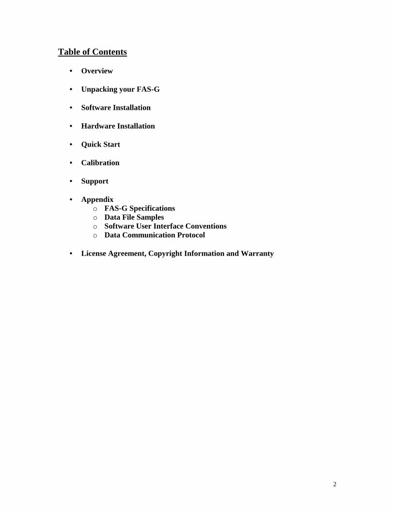
Handling a Path/File access error You may receive an error message when you first run the software. The error message will say Error: 75, Description: Path/File access error. This is caused sometimes when the files from the CD are copied to your hard drive. The error is easily curable.
• Exit the FAS-G application. • Locate a file named ‘FASGSettings.ini’ contained in the directory ‘C:\
FASG\Logs’. • Highlight the file with your mouse. • Click your right mouse button. • A pop-up window will appear. • Click the <Properties> menu item. • Another pop-up window will appear. • Use your mouse to uncheck the <Read-only> checkbox in the attributes section. • Click <OK>. • Re-launch the FAS-G application and the error will no longer occur.
9
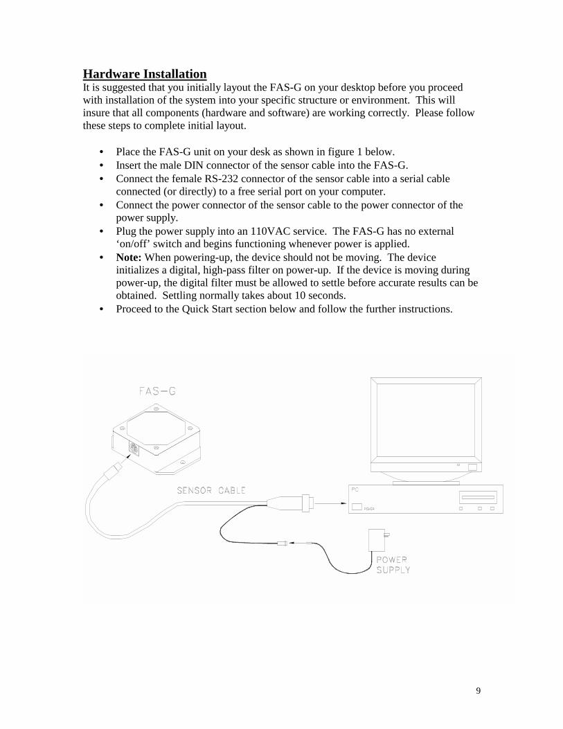
Hardware Installation It is suggested that you initially layout the FAS-G on your desktop before you proceed with installation of the system into your specific structure or environment. This will insure that all components (hardware and software) are working correctly. Please follow these steps to complete initial layout.
• Place the FAS-G unit on your desk as shown in figure 1 below. • Insert the male DIN connector of the sensor cable into the FAS-G. • Connect the female RS-232 connector of the sensor cable into a serial cable
connected (or directly) to a free serial port on your computer. • Connect the power connector of the sensor cable to the power connector of the
power supply. • Plug the power supply into an 110VAC service. The FAS-G has no external
‘on/off’ switch and begins functioning whenever power is applied. • Note: When powering-up, the device should not be moving. The device
initializes a digital, high-pass filter on power-up. If the device is moving during power-up, the digital filter must be allowed to settle before accurate results can be obtained. Settling normally takes about 10 seconds.
• Proceed to the Quick Start section below and follow the further instructions.

10
Quick Start When you have completed the instructions in the Software and Hardware Installation sections above, proceed as follows: Run Software Double-click the FAS-G Data Acquisition and Display software icon on your desktop. The Main screen will appear. Select Communications Port
• Go to Main screen. • Click <Tools>. • Click <Comm Port>. The Communication Port screen will appear. • Using your mouse, click the radio button representing the serial port that you
connected to the FAS-G. • Click <OK> to set the communication port and return to the Main screen.
Test FAS-G in Display Angles-Dials
• Go to Main screen. • Click <Display>. • Click <Angles-Dials>. The Angles-Dials screen will appear. • Click <File>. • Click <Sample>. A check will occur to the left of the menu item indicating
sampling is in progress. • The application will begin sampling the FAS-G and continuously display its
Uncompensated and Gyro Compensated angles. Congratulations You’re off and running! Refer to the Help file to discover all the functions that FAS-G Data Acquisition and Display software provides. You are also welcomed to contact our technical support staff on any matter at [email protected].

11
Calibration Background This option will allow the user to run a calibration routine on the FAS-G accelerometers if required. Note: The FAS-G is shipped calibrated and normally does not need to be recalibrated. Calibration in the field must be coordinated with the factory. Calibrating Accelerometers
• Physically place the FAS-G in the orientation shown below in figure below. Use a vertical surface that is flat and is perpendicular (90 degress) to the floor.
• On the Calibrate screen, click <File>, then click <Read>. You will notice that the computer is now continuously acquiring Ax and Ay bits data from the FAS-G.
• Physically rotate the FAS-G around the axis specified below in a slow and deliberate manner, keeping the FAS-G surface flat against the vertical surface. Spin about this axis over 360 degrees at least twice. Keep the FAS-G in this orientation.
Ax and Ay Calibration Orientation
• On the Calibration screen use your mouse in the Select frame to check ALL. • Click <File>, then click <Write>. • Calibration values will be written to the FAS-G. A confirming message will
appear. Click <OK>. • You may now remove the FAS-G from the surface. Calibration is complete.

12
Support Sales, Technical and Corporate: MicroStrain, Inc. 310 Hurricane Lane Williston, VT 05495 USA Phone: 802-862-6629 Fax: 802-863-4093 Email: [email protected] M-F 8:30am-5:00pm EST WWW: www.microstrain.com

13
Appendix
• FAS-G Specifications • Data Files Samples • Software User Interface Conventions • Data Communication Protocol

14
FAS-G Specifications Range Single axis (roll): 360 degrees A/D Resolution 12 bits D/A Resolution (output voltage) 12 bits Dynamic Compensation Closed loop digital control (0 to 50 Hz) Angle Resolution Roll: < 0.1 degrees (angle resolution specs. taken at most
aggressive filter setting) (static)
Temperature Drift Single axis: ±0.025 %/deg.C (temperature specs. represent 95% confidence intervals)
Nonlinearity 0.23% full scale (static) Repeatability 0.10 degrees Accuracy Roll: ±1.0 degrees typical (accuracy specs. taken at
constant ambient temp., tested with known sine and step inputs including angular rates to 300 deg/s)
Output Data Rate 6.5535 ms update interval (152.6 Hz) Analog Output Modes Gravity Inclination Angle-
0-360 deg 0-4096 v Gyro Compensated Inclination Angle-
+/-300 deg/sec max 0-4096v Angular Rate- ax, ay bits 0-5 v
Digital Output Format RS-232 serial (see appendix for Data Communications
Protocol) Transmission Rate 19200 bits/sec Supply Voltage 5.2 volts DC min. Supply Current 30 milliamps

15
Connector 8 pin mini DIN; mating connector available from MicroStrain or Digi-Key P/N CP-2080-ND or CUI Stack
P/N MD-80 Operating Temperature - 40 to 85 deg Celsius Enclosure (w/tabs) 64 mm by 90 mm by 25 mm; 2.5” by 3.5” by 1.0” Shock limit 1000g (unpowered); 500g (powered)

16
Data File Samples Sample of Angles Data File MicroStrain FAS-G Data File Version 1.2.2 Date file created: 11/12/01 Time file created: 12:48:08 PM Time(Seconds) Uncomp Gyro
0.03 91.9 321.3 0.07 91.9 321.1 0.08 91.9 321.1
Sample of Bits Data File MicroStrain FAS-G Data File Version 1.2.2 Date file created: 11/12/01 Time file created: 12:48:32 PM Time(Seconds) Gx Ax Ay Tick
0.01 2032 3910 2003 8145 0.03 2033 3909 2003 8149 0.05 2032 3909 2003 8152
Sample of Angles and Bits Data File MicroStrain FAS-G Data File Version 1.2.2 Date file created: 11/12/01 Time file created: 12:48:52 PM Time(Seconds) Uncomp Gyro Gx Ax Ay Pot Tick
0.03 91.9 210.6 2033 3909 2002 65312 10950.05 91.9 210.6 2032 3908 2002 65312 10950.07 91.9 210.5 2033 3904 2002 65312 1096
Sample of Scaled Sensor Data File MicroStrain FAS-G Data File Version 1.2.2 Date file created: 12/10/01 Time file created: 2:43:03 PM Time(Seconds) AxG AyG GValue
0.01 0.551758 0.813232 275.75 0.04 0.459229 0.881836 94.5 0.06 0.453125 0.847168 -43 0.08 0.449219 0.800537 -329.5
17
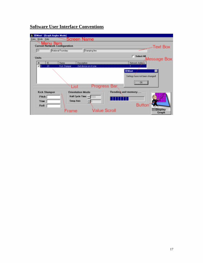
Software User Interface Conventions
18
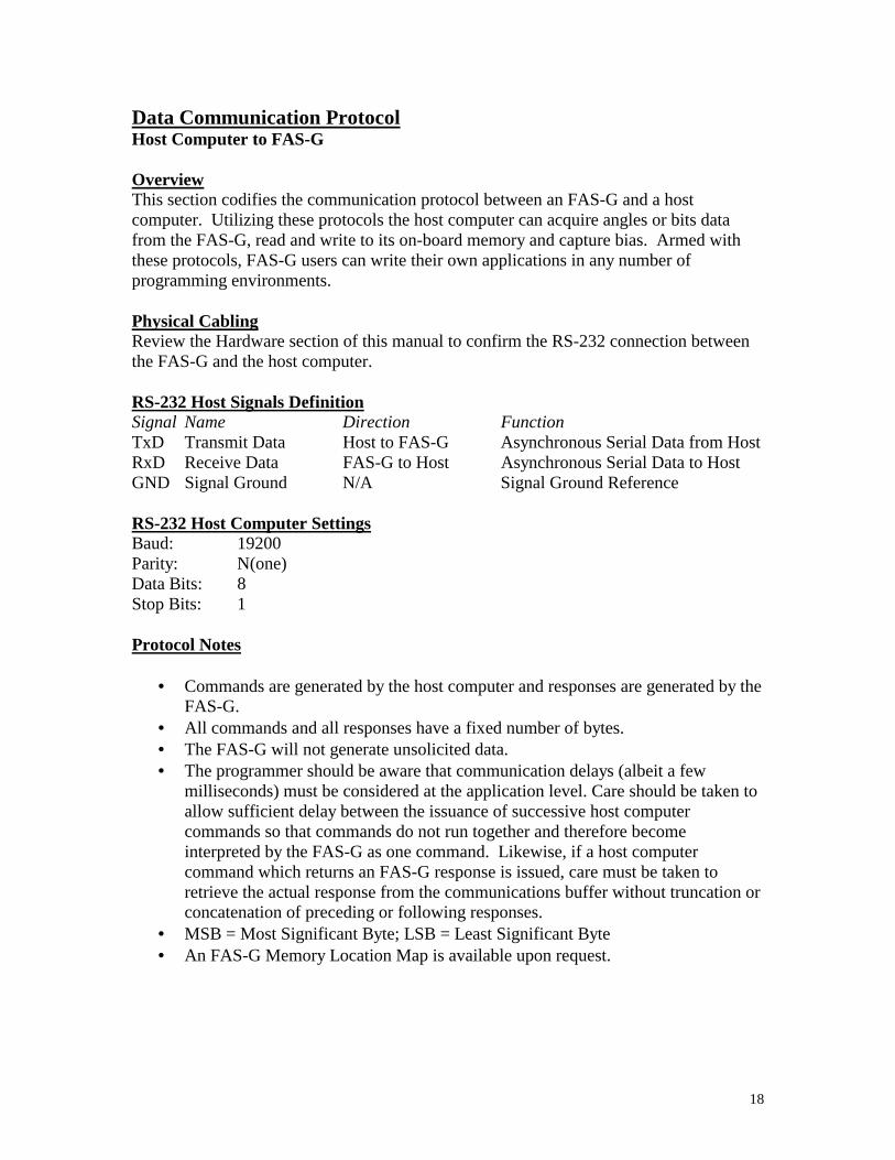
Data Communication Protocol Host Computer to FAS-G Overview This section codifies the communication protocol between an FAS-G and a host computer. Utilizing these protocols the host computer can acquire angles or bits data from the FAS-G, read and write to its on-board memory and capture bias. Armed with these protocols, FAS-G users can write their own applications in any number of programming environments. Physical Cabling Review the Hardware section of this manual to confirm the RS-232 connection between the FAS-G and the host computer. RS-232 Host Signals Definition Signal Name Direction Function TxD Transmit Data Host to FAS-G Asynchronous Serial Data from Host RxD Receive Data FAS-G to Host Asynchronous Serial Data to Host GND Signal Ground N/A Signal Ground Reference RS-232 Host Computer Settings Baud: 19200 Parity: N(one) Data Bits: 8 Stop Bits: 1 Protocol Notes
• Commands are generated by the host computer and responses are generated by the FAS-G.
• All commands and all responses have a fixed number of bytes. • The FAS-G will not generate unsolicited data. • The programmer should be aware that communication delays (albeit a few
milliseconds) must be considered at the application level. Care should be taken to allow sufficient delay between the issuance of successive host computer commands so that commands do not run together and therefore become interpreted by the FAS-G as one command. Likewise, if a host computer command which returns an FAS-G response is issued, care must be taken to retrieve the actual response from the communications buffer without truncation or concatenation of preceding or following responses.
• MSB = Most Significant Byte; LSB = Least Significant Byte • An FAS-G Memory Location Map is available upon request.

19
Command Table Base Command Definition 0x95 Send Angles Data 0x98 Send Bits Data 0x6C Capture Bias 0x66 Read Internal Non-Volatile Memory 0x65 Write Internal Non-Volatile Memory Send Angles Data command Function: To request current angles data from the FAS-G Command: 0x95 Response Data: 5 data bytes defined as follows: 0x95 Uncompensated Angle MSB Uncompensated Angle LSB Gyro Compensated Angle MSB Gyro Compensated Angle LSB Notes: To convert MSB and LSB to an integer, use this formula: Gyro Angle data = (MSB * 256) + LSB Uncompensated and Gyro are the same. To convert Angle data to Angle degrees, use this formula:
Angle degrees = Angle data * 360 / 65536 Both angles use same formula.
20
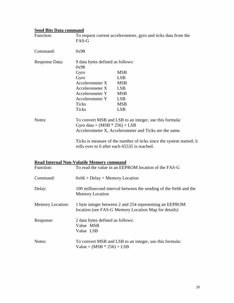
Send Bits Data command Function: To request current accelerometer, gyro and ticks data from the
FAS-G Command: 0x98 Response Data: 9 data bytes defined as follows: 0x98 Gyro MSB Gyro LSB Accelerometer X MSB Accelerometer X LSB Accelerometer Y MSB Accelerometer Y LSB Ticks MSB Ticks LSB Notes: To convert MSB and LSB to an integer, use this formula: Gyro data = (MSB * 256) + LSB Accelerometer X, Accelerometer and Ticks are the same.
Ticks is measure of the number of ticks since the system started; it rolls over to 0 after each 65535 is reached.
Read Internal Non-Volatile Memory command Function: To read the value in an EEPROM location of the FAS-G Command: 0x66 + Delay + Memory Location Delay: 100 millisecond interval between the sending of the 0x66 and the
Memory Location Memory Location: 1 byte integer between 2 and 254 representing an EEPROM
location (see FAS-G Memory Location Map for details) Response: 2 data bytes defined as follows: Value MSB Value LSB Notes: To convert MSB and LSB to an integer, use this formula: Value = (MSB * 256) + LSB

21
Capture Bias command Function: To capture bias on-board the FAS-G Command: Delay + 0x6C + Delay Delay: 100 millisecond interval between the sending of the 0x66 and the
Memory Location
Notes: Delays are issued to place an interval between the capture bias command and preceding or following commands
Write Internal Non-Volatile Memory command Function: To write a value to an EEPROM location of the FAS-G Command: 0x65 + Delay + 0x71 + Memory Location + Value MSB + Value
LSB + 0xAA Delay: 100 millisecond interval between the sending of the 0x65 and the
0x71 Memory Location: 1 byte integer between 2 and 254 representing an EEPROM
location (see FAS-G Memory Location Map for details) Value MSB: Value \ 255 Value LSB: Value And 255 Response: 2 data bytes defined as follows: Memory Location MSB Memory Location LSB Notes: To convert MSB and LSB to an integer, use this formula: Value = (MSB * 256) + LSB

22
License Agreement, Copyright Information and Warranty
TERMS AND CONDITIONS OF SALE AND LICENSE OF MICROSTRAIN EQUIPMENT AND SOFTWARE PURCHASED OR ACQUIRED FROM
MICROSTRAIN AND MICROSTRAIN DEALERS AT THEIR AUTHORIZED LOCATIONS
LIMITED WARRANTY and SOFTWARE LICENSE AGREEMENT
CUSTOMER OBLIGATIONS CUSTOMER assumes full responsibility that this hardware purchased (the "Equipment") and any copies of software included with the equipment, or licensed separately (the "Software", collectively the “Product”) meets the specifications, capacity, capabilities, versatility and other requirements of CUSTOMER. CUSTOMER assumes full responsibility for the condition and effectiveness of the operating environment in which the Product functions and for the Product’s installation. MICROSTRAIN, INC. a Vermont corporation, (“MicroStrain”) is the supplier of the Product which is the subject of this Warranty and License Agreement.
LIMITED WARRANTIES AND CONDITIONS OF SALE For a period of one hundred eighty (180) calendar days from the date of the MicroStrain invoice received upon acquisition of the Product, MicroStrain warrants to the original CUSTOMER that the Product and the medium upon which the Software is stored is free from manufacturing defects. This warranty is only applicable to acquisitions of MicroStrain Products by the original customer from MicroStrain. The warranty is void if the Product has been subjected to improper or abnormal use. If a manufacturing defect is discovered during the stated warranty period, the defective Product must be returned to MicroStrain for repair or replacement, in the discretion of MicroStrain along with a copy of the invoice. The original CUSTOMER'S sole and exclusive remedy in the event of a defect is limited to the correction of the defect by repair or replacement at MicroStrain's election and sole expense. MicroStrain has no obligation to replace or repair expendable items. MicroStrain warrants to the original CUSTOMER that spare parts for Equipment purchased will be available from MicroStrain for a period not to exceed two (2) years. MICROSTRAIN makes no warranty as to the design, capability, capacity, or suitability for use of the Software, except as provided in this paragraph. Software is licensed on an "AS IS" basis without warranty. The CUSTOMER'S exclusive remedy in the event of a Software manufacturing defect, is its repair or replacement within thirty (30) calendar days of the date of the MicroStrain invoice received upon license of the Software. The defective Software shall be returned to MicroStrain along with the invoice. Except as provided herein no employee, agent, franchise, dealer or other person is authorized to give any warranties of any nature on behalf of MICROSTRAIN. EXCEPT AS SPECIFICALLY PROVIDED HEREIN, MICROSTRAIN MAKES NO EXPRESS WARRANTIES, NOR ANY IMPLIED WARRANTIES OF MERCHANTABILITY

23
OR FITNESS FOR A PARTICULAR PURPOSE.
LIMITATION OF LIABILITY EXCEPT AS PROVIDED HEREIN, MICROSTRAIN SHALL HAVE NO LIABILITY OR RESPONSIBILITY TO CUSTOMER OR ANY OTHER PERSON OR ENTITY WITH RESPECT TO ANY LIABILITY, LOSS OR DAMAGE CAUSED OR ALLEGED TO BE CAUSED DIRECTLY OR INDIRECTLY BY "EQUIPMENT" OR "SOFTWARE" SOLD, LEASED, LICENSED OR FURNISHED BY MICROSTRAIN, INCLUDING, BUT NOT LIMITED TO, ANY INTERRUPTION OF SERVICE, LOSS OF BUSINESS, ANTICIPATORY PROFITS, INCIDENTIAL, SPECIAL, DIRECT, INDIRECT, OR CONSEQUENTIAL DAMAGES RESULTING FROM THE USE OR OPERATION OF THE "EQUIPMENT" OR "SOFTWARE." IN NO EVENT SHALL MICROSTRAIN BE LIABLE FOR LOSS OF PROFITS, OR ANY INDIRECT, SPECIAL, DIRECT OR CONSEQUENTIAL DAMAGES ARISING OUT OF ANY BREACH OF THIS WARRANTY OR IN ANY MANNER ARISING OUT OF OR CONNECTED WITH THE SALE, LEASE, LICENSE,USE OR ANTICIPATED USE OF THE "EQUIPMENT" OR "SOFTWARE." NOT WITHSTANDING THE ABOVE LIMITATIONS AND WARRANTIES, MICROSTRAIN'S LIABILITY HEREUNDER FOR DAMAGES INCURRED BY CUSTOMER OR OTHERS SHALL NOT EXCEED THE AMOUNT PAID BY CUSTOMER FOR THE PARTICULAR "EQUIPMENT" OR "SOFTWARE" INVOLVED. MicroStrain shall not be liable for any damages caused by delay in delivering or furnishing Equipment and or Software. No action arising out of any claimed breach of this Warranty or transactions under this Warranty may be brought more than one (1) year after the cause of action has accrued or more than two (2) years after the date of the MicroStrain invoice for the Equipment or Software, whichever first occurs.
SOFTWARE LICENSE MICROSTRAIN grants to CUSTOMER a non-exclusive paid-up license to use one copy of the MicroStrain Software on one computer, subject to the following provisions: Except as otherwise provided in this Software License, applicable copyright laws shall apply to the Software. Title to the medium on which the Software is recorded or stored (ROM) is transferred to CUSTOMER, but not title to the Software. CUSTOMER may use Software on a multi-user or network system only if either, the Software is expressly labeled to be for use on a multi-user or network system, or one copy of this software is purchased for each node or terminal on which Software is to be used simultaneously. CUSTOMER shall not use, make, manufacture, or reproduce copies of Software except for use on one computer and as is specifically provided in this Software License. Customer is expressly prohibited from disassembling or reverse engineering the Software. CUSTOMER is permitted to make additional copies of the Software only for backup or archival purposes or if additional copies are required in the operation of one computer with the Software, but only to the extent the Software allows a backup copy to be made.

24
CUSTOMER may resell or distribute unmodified copies of the Software provided CUSTOMER has purchased one copy of the Software for each one sold or distributed. The provisions of this Software License shall also be applicable to third parties receiving copies of the Software from CUSTOMER. All copyright notices shall be retained on all copies of the Software.
APPLICABILITY OF WARRANTY The terms and conditions of this Warranty are applicable as between MICROSTRAIN and CUSTOMER to either a sale of the Equipment and/or Software License to CUSTOMER or to a transaction whereby MicroStrain sells or conveys such Equipment to a third party for lease to CUSTOMER. The limitations of liability and Warranty provisions herein shall inure to the benefit of MICROSTRAIN INC., the author, owner and or licensor of the Software and any manufacturer of the Equipment sold by MicroStrain Inc.