Preliminary Design Review - AIAA OC Rocketry |...
66
AIAA Orange County Section Student Launch Initiative 2011-2012 Preliminary Design Review Rocket Deployment of a Bendable Wing Micro- UAV for Data Collection Submitted by: AIAA Orange County Section NASA Student Launch Initiative Team Orange County, CA Submitted to: Marshall Space Flight Center Huntsville, Alabama November 28, 2011 Image From: XPRS.ORG Project Manager Sjoen Koepke Website: http://AIAAOCRocketry.org
Transcript of Preliminary Design Review - AIAA OC Rocketry |...

AIAA Orange County Section
Student Launch Initiative 2011-2012
Preliminary Design Review
Rocket Deployment of a Bendable Wing Micro-UAV for Data Collection
Submitted by: AIAA Orange County Section
NASA Student Launch Initiative Team Orange County, CA
Submitted to: Marshall Space Flight Center
Huntsville, Alabama
November 28, 2011
Image From: XPRS.ORG
Project Manager Sjoen Koepke
Website: http://AIAAOCRocketry.org

Table of Contents
1. Summary of PDR Report 3 1.1 Team Summary 3 1.2 Launch Vehicle Summary 3 1.3 Payload Summary 3 2. Changes made since Proposal 3 3. Vehicle Criteria 4 3.1 Selection Design and Verification of Launch Vehicle 4 3.2 Recovery Subsystem 17 3.3 Mission Performance and Predictions 20 3.4 Interfaces and Integration 23 3.5 Launch Operations 25 3.6 Safety and Environment 27 4. Payload Criteria 27 4.1 Selection Design and Verification of Payload Experiment 27 4.2 Payload Concept Features and Definition 33 4.3 Science Value 33 4.4 Safety and Environment (payload) 34 5. Activity Plan 35 5.1 Status of Activities and Schedule 35 6. Conclusion 36 Appendix A Safety Precautions 37 Appendix B Hazards and Waste Threat and Disposal 42 Appendix C Risks and mitigation 44 Appendix D Materials Weights and Size 48 Appendix E Motor 50 Appendix F Flight Checklist 51 Appendix G Budget 57 Appendix H Time line 59 Appendix I AIAA OC Section Launch Safety Rules 60 Appendix J AIAA OC Section Shop Safety Rules 63 Appendix K Safety Rules when using Hazardous Materials 65
[2]

1. Summary of PDR Report 1.1. Team Summary
1.1.1. Team Name The AIAA OC Section Student Launch Initiative team name is OC Rocketeers.
1.1.2. Location The team location is: 20162 East Santiago Canyon Road Orange, CA 92869
1.1.3. Team Officials and Mentors The team officials and mentors are Bob Koepke, Jann Koepke, Michael Stoop, Andrea Earl, and Dr. Robert Davey.
1.2. Launch Vehicle Summary 1.2.1. Size
The total length of our Rocket will be 119.9 inches long, and the diameter of my rocket will be 5 inches.
1.2.2. Motor Choice The motor we chose is the Aerotech K-1050. This motor will keep our rocket under the speed of sound, and propel it a mile high.
1.2.3. Recovery System The recovery system consists of a total of four parachutes. The drogue and main parachute are located in the bottom section of the rocket. There will be another parachute located in the top section of the rocket. The final parachute will be on the UAV. The recovery electronics include the Raven altimeter and the G-Wiz Partners HCX, along with nine volt batteries and associated wiring. They are located in the electronics bay along with the payload. There is more information on this in the recovery subsystem of the Preliminary Design Review.
1.3. Payload Summary 1.3.1. Summarize Experiment
The payload of our rocket is an unmanned Arial vehicle (UAV). The experiment will begin once the UAV has been released from the sabot. It will be manually controlled by one of our team members until about 400 feet, where pre-determined commands will take over. Once deployed from the sabot, the UAV will use a telemetry kit to collect data. The telemetry kit will collect airspeed, altitude, compass heading, and artificial horizon through a 3 axis magnetometer. The UAV will also have a video feed in real time.
2. Changes made since Proposal ( 1-2 pages maximum) 2.1. Highlighted Changes
2.1.1. Changed made to vehicle criteria The vehicle is now 5 inch diameter instead of 6 inch diameter, we needed to lessen the weight of the rocket. The rocket also has a 4 inch extension for the sustainer cavity. The four inches come from the avionics bay; the avionics bay will be four inches shorter than the coupler.
2.1.2. Changes made to payload criteria
[3]

The payload criteria has not been changed 2.1.3. Changes made to activity plan
The activity plan has not been changed 3. Vehicle Criteria
3.1. Selection, Design and Verification of Launch Vehicle 3.1.1. Mission Statement, Requirements, and Mission Success Criteria
The mission statement is as follows: We, the OC Rocketeers, will construct and launch a rocket that will reach a mile high while deploying an UAV. The rocket will include a dual deploy recovery and will remain reusable.
The vehicle Requirements is as follows: Our team will design build and fly a rocket that has a dual deployment recovery system. It will reach an altitude of a mile at apogee. The data from the altimeters will be collected for the duration of the launch and reviewed after the vehicle has returned. The payload, the UAV, will deploy from the sabot at the second event and will detach from the parachute, be able to manually fly and will be able to fly to 3D way points in autopilot mode. The Rocket will remain reusable after the launch. The tracking system will work and enable the team to retrieve the rocket after each launch. The rocket will not exceed a mile, and will not land past 2,500 feet from the launch pad. The rocket will not accelerate faster than Mach1, and will not pose a safety threat to spectators or any other personnel. The vehicle Criteria is as follows: Our team’s rocket will be designed and built by the team. It will be flown and reach a mile high. The recovery system will use dual deployment and will work successfully. For the payload will be launched from the sabot at the second event and will be able to transmit the GPS location, video in real time and will be able to be flown manually and on autopilot. The rocket will not exceed mach1, pose as a safety threat and won’t travel outside of the 2,500 feet range from the launch pad. It will be a success if it meets these criteria, gathers useful data, and can be flown again without major repair.
3.1.2. Major Milestone Schedule ( Project initiation, design, manufacturing, verification, operations, and major reviews) • October 19, 2011Proposal Accepted • October 21, 2011 Trail Web Ex Confrence • October 22, 2011 Girl Scout Workshop • October 23, 2011 SLI Meeting (start writing PDR) • October 23 – November 23, 2011 Work on PDR • November 4, 2011 Website Presence Established • November 5, 2011 Girl Scout Workshop • November 20, 2011 Girl Scout Launch • November 23, 2011 PDR Subsections Finished • November 24 – 27, 2011 Proof reading of the PDR • November 28, 2011 PDR Submitted • December 5 - 14, 2011 WebEx PDR Presentation
[4]

• December 3 - 17 , 2011 Design Scale Model • December 10, 2011 Order Parts • December 11, 2011 Will Call • December 3-17 , 2011 Build Scale Model • December 16 - Ongoing Testing • January 15 , 2012 Launch Scale Model • January 23, 2012 CDR Submitted • January 24 - 31 , 2012 Finalize Full Scale Design • February 1 , 2012 Order Parts • February 2, 2012 Will Call • February 1 – 10, 2012 WebEx CDR presentations • February 11- 25 , 2012 Build Full Scale Rocket • March 10, 2012 Launch Full Scale Rocket • March 26, 2012 FRR Due • April 2 – 11 , 2012 WebEx FRR Presentation • April 18, 2012 Travel to Huntsville • April 19 – 20 , 2012 Flight Hardware and Safety Checks • April 21, 2012 Launch Day • May 7, 2012 PLAR Submitted
3.1.3. System Level Review Several systems are required to accomplish our mission. These are shown in the diagram below (subsystems of those systems are covered in subsequent sections):
3.1.3.1. Vehicle The vehicle is the rocket itself, it contains several sub systems: payload, recovery, and propulsion. All of these subsystems work together to create and form our project, without all of these working together our project would be incomplete and faulty. The payload was our team choice, we decide to launch a UAV from our Rocket that will fly around via RC down to 400 feet, and then fly to different way points and land autonomously. The recovery is one of the most important parts of rocket, if this is faulty the team could lose all electronics and data, the flight would be inconclusive, tragic, and poses a safety threat to the spectators. All of the recovery electronics will be located in the electronics bay, and our UAV will be launched via a sabot in the upper section of our rocket. The propulsion is the rocket engine. The team decided to use a K1050 motor from Aerotech.
3.1.3.1.1. Design Details
[5]

The Rocket was designed using Rocksim and is made up of 4 main parts. First there is the 24 inch long conic nose cone with a 6 inch long shoulder. The nosecone will be attached to the upper section via 3 screws. Next is the 51 inch upper section that will hold our 31 inch sabot and 84 inch upper section parachute. There will be a triple thickness bulkhead in the upper
section directly below the nosecone shoulder for the shock cord to attach to. The Sabot will be 31 inches long and split along the longer axis pivoting from the top end. It will contain our UAV and the UAV parachute before they are deployed. There will be a sealed I bolt on either side of the pivot point with one consecutive loop of shock cord run through them in order to force the sabot open when deployed. There will be a shock cord that attaches to the upper section bulkhead and the top of the sabot. Both the upper section parachute and a GPS unit will be attached to this shock cord. Next is the avionics bay. It is a 12 inch section that will house all of the recovery electronics. It overlaps 5.5 inches into both the upper bay and the lower bay with a 1 inch long coupler around the middle. Last is the 38.75 inch lower bay. This will house the motor mount, motor, drogue parachute, main parachute, tender descended, GPS and the nylon shock cord that the GPS and the drogue and main parachutes will be attached to. All of the outer body tubes and the coupler around the middle of the payload bay will have a 6 inch outside diameter. The inside diameter of all body tubes and the outside diameter of the payload bay will be 5.9920 inches. The outside diameter of the shoulder on the nosecone will be 3.875 inches. Lastly is the tail cone. It will be made out of a nose cone and some centering rings and accept a 54mm motor. Since we will be using a single use motor, our motor will use friction retention. There will be three fins equally placed around the outside of the lower bay flush with the bottom of the lower bay. The
[6]

fins will have a root chord length of 10.3333 inches, tip chord length of 8 inches, a sweep length of 7.4427 inches, a sweep angle of 53.285o, a semi span of 5.5 inches, and they will be 0.1875 inches thick. The fins will be made out of a G10 fiberglass frame with a light weight foam core all covered in a carbon fiber laminate. All exposed pieces of the Rocket will be made out of carbon fiber. The recovery section including the electronics and parachutes are covered in detail in section 3.2.
Component Material Qty Weight (grams)
Total Weight (grams)
Length (inches)
Width (inches)
Thickness (inches)
Vehicle
Nosecone Carbon Fiber 1 360 360 24 5 0.028
Upper Body Tube Carbon Fiber 1 1003 1003 47.5 5 0.056 Bulkhead G-10 Fiberglass 1 114 114 n/a 5 0.18
Sabot
Bulkhead G-10 Fiberglass 2 114 288 n/a 5 .18 Coupler Carbon Fiber 1 211 211 31 5 .028
Middle Body Tube Carbon Fiber 1 21 21 1 5 0.056
Avionics Bay
Coupler Carbon Fiber 1 253 253 12 5 0.028
Bulkhead G-10 Fiberglass 2 114 228 n/a 5 0.18
Lower Body Tube Carbon Fiber 1 818 818 38.75 5 0.056
Fins Carbon Fiber, G
10 Fiberglass, Balsa 3 72 217 10.333 n/a 0.06
Launch Rail Lug Aluminum 2 4 4 1.526 0.75 0.29
Tail cone assembly Polystyrene 1 75 75 1.25 5 n/a Motor Retention Aluminum 1 42 42 1 2.6 0.09
Propulsion
Aerotech K1050 Motor APCP, Plastic 1 2128 2128 25 2 n/a
The final rocket is custom designed to our needs and has the following characteristics: • Length: 115.98 inches • Diameter: 5.02 inches • Span: 16.02 inches • Mass: 333 ounces • Center of Gravity: 71.45 inches behind the nose tip • Center of Pressure: 86.93 inches behind the nose tip • Stability Margin: 3.10
[7]

To select a motor we needed to have all of the details of components for the rocket (major vehicle components are in the table above, for complete list see appendix D). The total final weight from our table was 258 ounces, or 20.8 pounds (this varied as we loaded different motors). This corresponded closely with the weight of the individual components entered into Rocksim using their data base. We selected several different motors made by Cesaroni and Aerotech, since both manufacturers have a reputation for being consistent and reliable. Our target altitude was just under 1 mile. From the simulations, the K1050 single use motor carried our rocket to 5,177 feet – just short of the needed 5,280 feet (better to err on the low side of 1 mile) with a burn time of 2.3 seconds. Specifications of this motor as well as the thrust curve are in Appendix E.
Engine Total Impulse (Ns)
Total Mass (g)
Max Altitude (ft)
Max Velocity (ft/s)
Max Accel (ft/s/s)
K 1440-WT
2368.3 1893g 4935 778 741
K660 2437.5 1949g 5100 683 351 K590-DT 2415 1994g 5122 637 608 K1130-BB
2550.7 2574g 5126 754 482
K1050-SU
2530.0 2128g 5178 766 458
If the design should need to change requiring less thrust, engines are available (e.g. the K590, K660, and k1440) as shown in the table above. However, if more thrust is required, the only option is the K1130 (though is gives a lower altitude). This means that more than likely we would have to modify our design to gain altitude. This motor selection also keeps the vehicle from exceeding mach1, another requirement.
3.1.3.2. Launch System When the team launches the rocket there’s a lot that contributes to it. To launch a rocket it requires: a launch rail, a launch controller with a safety interlock system, a weather station, wire/cable, two garden tractor batteries, alligator clips, a remote relay, and a fire extinguisher. The team’s rocket will use launch rail guides, thus we need a launch rail to launch. To actually launch the rocket you need a launch controller with a safety interlock system which needs a power supply which is the 12v garden tractor battery, wires/cables run out to the launch pad to a
[8]

remote relay which attaches to a second 12 v battery. The launch controller closes the remote relay that provides power to the igniter. In this way, less power is lost in the long wire run from the controller to the pad. Just in case anything happens to our engine we will have a fire extinguisher on hand. Before we actually launch our rocket we need to check our weather station to make sure the wind speed is less than 20 miles an hour.
3.1.3.3. Tracking System The tracking system allows the team to find their rocket after it is launched, keep in mind that the rocket could be up to 2,500 away from the pad. The electronics we will be using are: Big Red Bee Beeline GPS transmitter, Yaesu VX-6R Transceiver, Bionics Tiny Track 4, and Garmin E-Trex Vista. The Big Red Bee will be located in the nose cone of the rocket, this so that the radio waves will not interfere with the electronics in the electronics bay. The Big Red Bee will send radio waves to the Yaesu VX-6R Transceiver, the transceiver will be connected to the Bionic Tiny Track 4, which will take the audio from the Yaesu and convert them into a digital signal. The Garmin translates that into a location that will show both our location as well as that of the vehicle on the screen. The RF signal from the Big Red Bee can also be used with a Yagi antenna as a radio direction finder.
3.1.3.4. Retrieval The retrieval of the rocket is the most simplistic of all the system. All we need is a group of ready people (people from our team) who are willing to walk to retrieve the rocket. Hopefully they are wearing comfortable shoes that day. With the retrieval, they have to be sure that they recover all parts just in case something malfunctioned.
3.1.3.5. Data Analysis Data Analysis is when the team collects their data from the flight. We would collect the data from both flight computers to see the curve of the flight, when the ejection charges were fired and to see what height they acquired. For this process we would need the electronic device we were taking information from, a computer to download the information to, and a download cable so we could download the information.
3.1.3.6. System Performance and Characteristics We expect all systems to work together so that our project is successful. All of our major systems include: vehicle, launch, tracking, retrieval, and data analysis. We expect the vehicle to work well with all of its subsystems. The vehicle contains the subsystems: recovery, payload, and propulsion. The recovery has to fire a total of six charges, two for the drogue, two for the UAV, and two for the main at Apogee, 1000 feet, and 900 feet respectively. The recovery should return the rocket safely to the ground, within the 2,500 feet range. The UAV will launch and land successfully. The propulsion will launch the rocket to a total of mile high without exceeding it. The motor that will be used is a K1050 by Aerotech. The launch subsystem will launch the rocket on a
[9]

rail guide 200 feet away from the launch controller with a safety interlock system. The rocket will reach a safe speed before leaving the launch pad. Tracking the rocket is essential because it enables us to record the data from the launch. The Big Red Bee, Yaesu VX-6R Transceiver, Bionics Tiny Track 4, and Garmin E-Trex Vista will work together to give us an accurate location. We will retrieve the rocket using the tracking system. We will have a group of team members use the tracking system to find the rocket and return it. After the rocket is returned the electronics will be plugged into a computer and the data will be uploaded. After that the team will for analyze the data to reach a conclusion regarding the effect of the flight
3.1.3.7. Evaluation and Verification Metrics The vehicle can be watched and tested on the ground to verify that the system will work in flight. We can download data from the flight computers to verify that it worked completely. For the payload the UAV will deploy and land safely. The launch can be controlled by the members, but they will be launching at a ROC launch. They will launch on a launch rail, and be within 2,500 of the launch pad. They will also not exceed mach1 and will not have a height higher than a mile. The tracking system will work and successfully guide the team to their rocket. The members will retrieve their rocket using the tracking device. The members will record the data from the launch, and write a conclusion statement using the results.
3.1.4. Subsystems 3.1.4.1. GPS Subsystem
The GPS and Downlink Transmitter for the vehicle will be a Beeline GPS from Big Red Bee measuring 2 7/8" x 1 1/4", the antenna is 6.25" long. This device is an integrated GPS receiver and 70cm amateur transmitter (two mentors to the team have an amateur radio license) with a micro controller translating the position received from the GPS receiver
into AX.25 APRS (Automatic Packet Reporting System) information packets containing the latitude, longitude, and altitude of the rocket. This information is then transmitted as audio information via an integrated FM transmitter on any frequency of our selection in the 70 cm amateur radio band (420 – 450 MHz). The device is powered from a single cell 750mAH lithium battery (approximately 4.2 volts) which provides power for up to 10 hours. The device will also store 10 minutes of location data after launch is detected.
We will be using two Big Red Bee Beeline GPS transmitters on the vehicle. One of the GPS transmitters will be located on the 1 inch nylon shock cord in the Top Section. The GPS transmitter will be protected using Styrofoam casing. The second GPS transmitter will be located on 1 inch nylon shock cord
[10]

in the sustainer section of the rocket. The second GPS transmitter will also be protected in a Styrofoam casing.
3.1.4.2. Recovery Subsystem The vehicle will use redundant dual deployment for recovery and one more ejection for payload. The top section will be connected to the sabot with the parachute in between via a nylon shock cord, and the sustainer and the avionics bay will also be connected via a nylon shock cord. However, the avionics bay and the sustainer will have both a drogue and a main parachute between them. Recovery will occur in three phases – near apogee a small drogue parachute will be deployed that is designed to slow the rocket for initial decent. Much later, at an altitude of 1000 feet, our top section will separate deploying the UAV (with its own parachute) and deploying a larger parachute just for the top section and sabot. This separation will also lighten the sustainer and avionics bay allowing it to slow down. Finally the main will deploy via a fruity chutes Descender at 850 feet slowing us down to a safe landing speed. Each half of the redundant recovery electronics will use a different sensing device. In this way, if there is a bug in the design of either device that would affect the recovery during our flight it will not be replicated in the backup electronics. Each of the two recovery electronics has its own separate battery capable of powering the electronics for a minimum of 1 hour dwell time plus flight time. That battery is disconnected through an interlock key switch accessible on the outside of the vehicle approximately 3.5 ft above the fin end of the rocket so that the electronics is unarmed and not powered until it is safe to do so (when on the launch pad). They key can be removed only when the switch is locked ON. The recovery electronics will ignite a measured portion of gunpowder using an electric match. Recovery electronics are totally independent of the payload electronics and power. To assure that the recovery electronics will be minimally affected by the RF transmitters on board the vehicle, the interior of the avionics bay is sprayed with MG Chemicals SuperShield. One to two mil coating provides 40dB - 50dB shielding across a frequency range of 5 to 1800MHz. On board transmitters are at or near 420, 450, 900, and 1280 MHz. We also have receivers at 2.4GHz but do not transmit.
3.1.4.3. Scientific/Engineering Payload Subsystem The payload consists of an Unmanned Aerial Vehicle. Once deployed at 1000 feet, the UAV will collect telemetry using a telemetry kit. The telemetry kit consists of a barometer, air speed sensor, artificial horizon, voltage and current sensors for batteries, and GPS module. The UAV will be flown manually until about 400 feet. Then, the UAV will switch to autopilot and follow preset commands. This gives the experiment the ability to possibly transfer to military operations requiring the deployment of an unmanned vehicle to take footage of any unknown or potentially deadly landscape. The motor that the UAV will be using is an Alpha 480 brushless motor using 22-28 Amps. More information about the payload subsystem can be found in section for 4 of the PDR.
3.1.4.4. Scale Model and partial Subsystem
[11]

Our scale model will be a 0.6 scale rocket with a 38mm motor mount. This will make it have a 3 inch diameter and be roughly 70 inches tall. We will use a J335-RL to propel the rocket up to approximately 1500ft. we will deploy a drogue at apogee, and our upper section parachute at 800ft. At this time we will deploy a weight with a parachute to simulate our UAV and at 500ft we will deploy our main parachute. We do recognize that we should be making a carbon-fiber scale model; however, we currently do not have the funds to do so. If enough money ends up being raised our scale model will have a carbon fiber based airframe. At the time of our scale model we also plan to have an RC vehicle built that will be capable of basic flight under RC and possible autonomous as well. If funding and time permit we would like to build a scale UAV capable of being launched from our scale model rocket.
3.1.4.5. Full Scale and Full subsystems Our full scale model will be 119 inches tall and have a 54mm motor mount. We will use an Aerotech k1050 single use to propel the rocket up to approximately 5280ft. we will deploy a drogue at apogee, and our upper section parachute at 1000ft. At this time we will deploy our UAV and at 850ft we will deploy our main parachute.
3.1.5. Performance Characteristics for the System and Sub System and determine evaluation and verification metrics The performance characteristics for the rocket are as follows: The rocket will reach a mile high, the rocket will not exceed mach1, the rocket will not travel outside of a 2,500 fee range from the launch pad, the rocket will use GPS and the GPS ground station will properly display the location, the rocket will use dual redundant dual deploy recovery system, the payload will work successfully and the rocket will remain reusable. The verification of metrics will be through the data recorded on the HCX and on the Raven, along with observation.
3.1.6. Verification Plan and Status 3.1.6.1. GPS Subsystem
Big Red Bee Beeline GPS • Validate that each GPS transmitter is actually transmitting
on a frequency in the 70cm ham band. We should hear tones on the Yaesu VX-6R. Status: Status: Need to validate from last year.
• Validate the ground station is encoding GPS signals by listening on 144.390 MHz, a frequency used in the Los Angeles area for APRS to see data on the Garmin. Status: Need to validate from last year
• Validate the GPS transmitter and ground station can work together by setting up the transmitter and receiver and validating to a known location. Status: Need to validate from last year
[12]

• Range Testing (ground): Repeat the test above in the desert with the GPS transmitter on the ground. Increase the distance between transmitter and receiver, noting the distance when the decoding stops and when the signal is so weak it cannot be used for direction finding. We would like to see 2500 ft. Status: Need to validate from last year
• Range Testing (elevated): Repeat the test above with the GPS transmitter on the top of an 8 foot step ladder. We need to see at least one mile. Status: Need to validate from last year
3.1.6.2. Recovery Subsystem • Validate the team’s understanding of the Raven altimeter and
HCX flight computers and how they are programmed by an application running on the PC. During this test we will also make cards indicating the meaning of the beep sequences from each flight computer for use during actual launches – some sequences indicate errors and would stop the launch until fixed. Status: We programmed an Entacore AIM flight computer since it was available – it should be similar to the Raven and HCX. This step will be repeated on the Raven and HCX.
• Bench test the Raven altimeter and HCX flight computers by connecting the batteries and running the flight simulation supplied by the manufacturer. The e-matches are replaced by LEDs (with a 100 ohm series resistor) and each flight computer connected to the PC running the manufacturer’s configuration program. A simulation is then run validating that the LEDs light at the appropriate times when the ejection charges should have fired. Status: Run on the Entacore AIM USB flight computer. Not started on the Raven or HCX.
• Bench test simulating altitude with a vacuum chamber. Each flight computer is programmed using the manufacturer’s configuration program. The batteries and LEDs are connected and the entire assembly is placed in a sealed chamber. Pressure is then lowered by sucking on an attached tube to simulate launch and altitude. Pressure is next returned to ambient – this process simulates a flight (using the barometric altimeter) and the LEDs should light when the ejection charges would fire. We have access to a Druck DPI 605 Pressure Calibrator to use instead of sucking on the tube. Status: Not started.
• Field testing: The flight computer will be set up in a rocket body and payload section to simulate the actual vehicle and payload. E-matches with black powder will be used rather than LEDs. Each flight computer will be connected via USB to the PC and a simulation run. This will validate full simulated functionality of the flight computer, level of black powder required, ability to shear
[13]

the nylon pins, and the ejection of the parachute. This test will be repeated as necessary to adjust the amount of black powder required to assure full parachute deployment without damage to the rocket. And it will validate the payload section is fully sealed and protected from the black powder ejection charge. Status: Not started.
3.1.6.3. Scientific/engineering payload subsystem • Bench test of payload subsystem electronics. All electronics will
be tested on the ground. Results are observed to see if the individual electronics work properly. Status: Not Started
• Bench test of the payload subsystem in a store bought plane. The results will be observed to see if the indivual subsystems work together. Status: not started.
• Field test of the payload subsystem. Similar to above, but the payload will be flown and will collect and report back data to the ground station. The flight will be repeated in different states of weather Status to assure reasonable data is collected. Status: not started.
3.1.6.4. Scale Model and Partial subsystem • A scale model of the full sized vehicle presented in this
document will be designed and simulated on Rocksim (based upon this document and NASA feedback). The vehicle will use a 3 inch body tube and an identical design and layout. Due to size constraints, it will be flown without the payload. Status: Vehicle in the early stages of design.
• The scale vehicle will then be built and flown. It should fly to the altitude predicted by Rocksim simulations with the drogue deployed at apogee and the main at 900 feet. Status: not started
3.1.6.5. Full Scale and Full Subsystem • The full sized vehicle as presented in this document (with
modifications as directed through NASA feedback) will be built and flown. This vehicle will have a full avionics bay with redundant dual deployment. It will fly on an Aerotech K1050 single use motor. We will launch at a regular, scheduled ROC launch at Lucerne Dry Lake in the Mojave Desert to take advantage of their FAA waiver. If for some reason scheduling does not permit launching at an ROC launch, we have our own launch equipment and will obtain an FAA waiver to launch at the same location using our own launch equipment.
3.1.7. Risks The risks can be found in appendix C. This covers risks such as what could go wrong with the rocket as well as personnel risks top the team and spectators.
3.1.8. Planning of Manufacturing, Verification, Integration and operations ( include component testing, functional testing and static testing)
[14]

Once the design has been approved by NASA we can begin manufacturing. In preparation, we have obtained a bendable wing and had it laser imaged, once it was imaged it was transferred into a solid works document. This allows us to be able to make a mold of the bendable wing using the solid works image in a CNC machine. We have some of the electronics and most of the vacuum bagging supplies. Sources have been identified for most components: http://aeroconsystems.com/cart/products/Featherweight_Raven_Altimeter_Flight_Computer235-0.html
Component Vendor /Manufacturer URL Scale size vehicle components
Fiberglass body tube, Nose cone, bulkheads and other miscellaneous parts are available from Giant Leap Rocketry
http://www.giantleaprocketry.co m
Full Scale Vehicle components
Carbon fiber body tube and Nose cone are available from Performance Rocketry
http://www.performancerocketr y.com/
Full Scale Vehicle components
Fiberglass bulkheads and centering rings can be found at Giant leap Rocketry
http://www.giantleaprocketry.co m
Additional vehicle components
Payload bay coupler, longer body tube couplers, motors, e-matches, black powder from What’s Up Hobbies (vendor at ROC launches)
http://whatsuphobby.com
Recovery Electronics Raven flight computer available from Aerocon Systems
http://aeroconsystems.com
GPS transmitter Beeline GPS transmitter and download cable direct from manufacturer
http://www.bigredbee.com
Parachutes Parachutes, launch lugs, miscellaneous parts, launch rail from vendor Giant Leap Rocketry
http://www.giantleaprocketry.co m
Parachutes Heavier parachutes- both main and drogue from Rocketman Enterprises
http://www.the-rocketman.com
West System Adhesive West Systems Epoxy is available from the local West Marine store
http://www.westmarine.com
Launch Pad Controller We are using the 6 pad controller from Pratt Hobbies
http://www.pratthobbies.com
“Remove before flight” flags
Flags and some electronics including the key switches are available from Aerocon Systems
http://aeroconsystems.com
Vacuum Bagging Supplies
Release film, carbon fiber, breather film, vacuum bagging film and Heat resistant tape are available from Aircraft Spruce
http://www.aircraftspruce.com/
UAV electronics The arduPilot and shield, MediaTek, Xbee Telemetry Kit, servos and Sony DV-D3130CDNH camera are available from DIY Drones
http://diydrones.com/
UAV electronics The Alpha 480 Brushless motor, Volcano Proton 30A, and the Spectrum DX7 Transmitter are available from Hobby Partz
http://www.hobbypartz.com/
UAV electronics Other UAV supplies is available from Ultimate hobbies
http://www.ultimatehobbies.co m/
Most of the construction will be done at the home of one of the mentors. All components will be assembled using West System Epoxy. Fin alignment will be assured using the BMI Fin Jig. Verification and testing will be done at
[15]

the home of one of the mentors as well as at the launch site at Lucerne Dry Lake in the Mojave Desert in Southern California. John Coker (who also brings us thrustcurve.org) did a strength study of various epoxies which showed West Systems and Aeropoxy as far superior to hobby store epoxy (<http://www.jcrocket.com/adhesives.shtml> ). We have chosen West Systems since it is easier to obtain than Aeropoxy.
3.1.9. Confidence and Maturity of the Design Several members of the team have been using Rocksim for many years and when the flight simulations on Rocksim have been successful with reasonable stability margin the flights have always been successful and safe. One of the teams mentors design and sells rockets as a business and is our guide for design and assembly.
3.1.10. Dimensional Drawings The drawing below is the whole rocket with measurements listed and locations of where different components are located
3.1.11. Electrical Schematics for Recovery System Below is the electrical schematic for the Recovery System. The electrical schematic includes the two altimeters, the raven and HCX,
[16]

3.1.12. Mass Statement The mass statement can be found in Appendix D.
3.2. Recovery Subsystem 3.2.1. Attachment Scheme
The attachment scheme is as follows. The upper section has two connection points one on a bulkhead with a “U” bolt which is located one inch down from the shoulder of the nose cone. The second attachment point is on a “U” bolt on the sabot. The Sustainer section also has two attachment points, the first attachment point will be a “U” bolt on the centering ring for the motor mount and the second attachment point is on a “U” bolt on the Avionics bay. The shock cord the team will be using is one inch nylon shock cord which will be attached to the “U” bolts using quick links.
3.2.2. Recovery Electronics In the recovery system we have two flight computers, Raven flight computer and G-Wiz Partners HCX. Our team is using two different types of altimeters so that if one malfunctions, or has a design flaw, the other one shouldn’t. We hope by using this system we won’t have to worry about a faulty recovery system. The two systems are electrically isolated and each has an interlock switch which will allow the recovery electronics to be off until the vehicle is on the launch pad ready for launch.
3.2.3. Black Powder Charges The black powder charge is necessary for successful deployment of the parachute. Our team will have three black powder charges, one for the drogue parachute, one for the top section and one for the main parachute. Our team will use 4444F gunpowder. For the first ejection charge, the drogue parachute, the cavity size is 12.75 inches and we are using 5 inch body tube. Then the team calculated what the PSI we need is. We are using
[17]

4 #2 nylon screws which need 35 pounds each, we need 140 pounds of force. The equation we used to calculate PSI is as follows PSI = (Pounds of Force) / (π x r²) The pounds of force the team will use is 250 for the drogue (the 140 pounds of force only accounts for sheering the pins) and 300 for the upper section ( we need to push the sabot out along with shearing the pins).
250 pounds of force PSI = (250) / (3.14 x 2.5²) = 12.73 Rounded PSI to 13
300 pounds of force PSI = (300) / (3.14 x 2.5²) = 15.28 Rounded PSI to 15.5
To calculate the amount of gunpowder we need we will use the following formula: Grams of black powder = C x D² x L C = psi x 0.0004
C = 13 x 0.0004 = .0052 (Drogue) C = 15.5 x 0.0004 = .0062 (Upper)
D = Diameter of the airframe in inches D = 5² = 25
L = Length of the cavity to be pressurized in inches L = 12.75 (Drogue) L = 8.5 (Upper)
Black Powder Calculation for the Drogue Grams of black powder = 0.0052 x 25 x 12.75 = 1.6575 Rounded to 2 grams
Black Powder Calculation for the Upper section Grams of Black Powder = 0.0062 x 25 x 8.5 = 1.38125
Rounded to 1.5 grams
The main parachute uses a L2 Tender Descender from Fruity Chutes. The recommended amount of black powder is .33 grams of 4444F gunpowder. The team will be using .33 grams of 4444F gunpowder.
3.2.4. Parachutes The initial size estimate of the parachutes required is based upon the estimated weight of the vehicle. And the liftoff weight will be different than the weight under recovery since the propellant will have burned off. For the initial estimates, we chose 6 different rocket engines across a rather narrow impulse range. The weights of those engines are as follows:
Motor Grains Loaded weight (g) Propellant weight (g) Burnout weight (g)
K828FJ No Data 2223g 1373g 850g
K750-RL 6 2057g 1321g 733g
K820-BS 6 1982g 1164g 750g
[18]

K590-DT 6 1994g 1169g 755g
K660 6 1949g 1177g 734g
K1050 No Data 2128g 1362g 776g
For the vehicle weight estimate, we built a model in Rocksim with all weights accounted for totaling 7275g without a motor loaded. The top section weighs 111oz and the bottom section (with burnt motor) weighs 139oz. The following table was derived by using an on-line calculator for parachute size (http://www.aeroconsystems.com/tips/descent_rate.htm) with a main parachute size of 84”, a drogue size of 24”, UAV size of 36”, and the top section size of 60” (based upon commercial availability).
3.2.4.1. Drogue Parachute We used the following site to calculate the descent rates by comparing the mass of the rocket and the diameter of the parachute. <http://www.aeroconsystems.com/tips/descent_rate.htm>.The drogue parachute is 24 inches in diameter, made of rip stop nylon and it descends at a rate of 77.75 feet per second and will lower to 17.43 after the second event. It will collapse once the main parachute is deployed. The drogue parachute will be deployed by the electronics at apogee.
3.2.4.2. Main Parachute We used the following site to calculate the descent rates by comparing the mass of the rocket and the diameter of the parachute. <http://www.aeroconsystems.com/tips/descent_rate.htm>.This parachute is 84 inches long in diameter and made of rip stop nylon. The descent rate is 17.43 feet per second. The parachute will lower the rocket down to the ground from an altitude of 900 feet. The main parachute will be deployed when the vehicle returns to an altitude of 900 feet on the drogue.
3.2.4.3. Upper Section Parachute We used the following site to calculate the descent rates by comparing the mass of the rocket and the diameter of the parachute. <http://www.aeroconsystems.com/tips/descent_rate.htm>.This parachute is 60 inches in diameter and made of rip stop nylon. The descent rate is 17.26 feet per second. The parachute will be deployed at 1000 feet. This ejection charge will also push out the sabot and release the UAV.
3.2.4.4. UAV Parachute We used the following site to calculate the descent rates by comparing the mass of the rocket and the diameter of the parachute. <http://www.aeroconsystems.com/tips/descent_rate.htm>. This parachute is 36 inches and made of rip stop nylon. The descent rate is 18.42 feet per second. This parachute will be released after the second
[19]

event when the sabot is pushed out of the Upper section body tube and hinges open. This will happen roughly around 1,000 feet.
3.3. Mission Performance and Predictions 3.3.1. Mission Performance Criteria
In order for our mission to be successful, the rocket must launch safely and achieve a height of roughly 1 mile. Our drogue parachute will deploy at apogee, and we will have separation of the upper and lower sections at 1000 feet deploying the UAV. At 850 our main parachute will deploy and all sections of our rocket will land successfully and not sustain damage.
3.3.2. Flight Profile Simulations, Altitude Predictions with simulated vehicle data, component weights and simulated motor thrust curve We ran many different simulations to get our rocket as close to one mile as possible below are some of the flight simulations that we ran. Component weights can be found in appendix D and the motor thrust curve can be found in appendix E.
3.3.3. Stability Margin, Simulated Center of Pressure and Center of Gravity Relationships and locations Rocksim calculated the center of gravity at 71.5 inches back from the tip of the nose cone and the center of pressure at 86.9 inches back from the tip of the nose cone giving a stability margin of 3.10.
3.3.4. Calculated Kinetic energy at landing for each independent and tethered section of the launch vehicle The formula that our team used is below.
K.E. = (½) (m x .434) (v x .305) ² (.738) M = mass in pounds V = Velocity in ft/sec K.E. = Kinetic Energy in ft lb force
We have three possible sections, the Upper section, the Sustainer and the UAV. Below is the Mass of the section in pounds
Upper Section Mass = 5.5 Sustainer Mas = 10.6 UAV Mass = 1
Below is the calculated Velocity in ft/sec. Upper section descent rate = 17.26 Sustainer descent rate = 17.43 UAV descent rate = 18.42
[20]

The Upper Section Kinetic Energy Calculation K.E. = (1/2) (5.5 x .434) (17.26 x .3050 )² (.738) = 24.40956537
Rounded to 24.4 ft lb force The Sustainer Section Kinetic Energy Calculation
K.E. = (1/2) (10.6 x .434) (17.43 x .3050)² (.738) = 47.97515802 Rounded to 48 ft lb force The UAV Kinetic Energy Calculation
K.E. = (1/2) (1 x .434) (18.42 x .3050) ² (.738) = 5.054695823 Rounded to 5.1 ft lb force
The Kinetic Energy that the upper section has at landing is 24.4 feet pound force The Kinetic Energy that the sustainer section has at landing is 48 feet pound force. The Kinetic Energy that the UAV would have at landing is 5.1 feet pound force.
3.3.5. Calculated Drift
Drogue (5280ft-1000ft)
Weight (lbs.) Parachute size (in)
Velocity (ft/s) Wind Speed (MPH)
Drift (ft)
17.8124 24 77.75 5 404 17.8124 24 77.75 10 807 17.8124 24 77.75 15 1211 17.8124 24 77.75 20 1614
UAV (1000ft-0ft) Weight (lbs.) Parachute size
(in) Velocity (ft/s) Wind Speed
(MPH) Drift (ft)
1 24 18.42 5 398 1 24 18.42 10 796 1 24 18.42 15 1194 16 24 18.42 20 1593
Top Section (1000ft-0ft) Weight (lbs.) Parachute size
(in) Velocity (ft/s) Wind Speed
(MPH) Drift (ft)
5.49999 60 17.26 5 425 5.49999 60 17.26 10 850 5.49999 60 17.26 15 1275 5.49999 60 17.26 20 1700
[21]

Drogue after Upper section (1000ft-850ft) Weight (lbs.) Parachute size
(in) Velocity (ft/s) Wind Speed
(MPH) Drift (ft)
10.6249 24 61 5 18 10.6249 24 61 10 36 10.6249 24 61 15 54 10.6249 24 61 20 72
Main (850ft-0ft) Weight (lbs.) Parachute size
(in) Velocity (ft/s) Wind Speed
(MPH) Drift (ft)
10.6249 84 17.43 5 358 10.6249 84 17.43 10 715 10.6249 84 17.43 15 1073 10.6249 84 17.43 20 1431
Total Distance traveled Upper section Wind Speed (MPH) Total distance traveled (ft)
5 829 10 1657 15 2486 20 3314
Total Distance Traveled Sustainer Wind Speed (MPH) Total Distance Traveled (ft)
5 780 10 1558 15 2338 20 3117
Total Distance Traveled UAV Wind Speed (MPH) Total Distance Traveled (ft)
5 398 10 769 15 1194 20 1593
[22]

3.4. Interfaces and Integration 3.4.1. Payload Integration Plan
The payload will be housed in a sabot until it is deployed when the second event (the second ejection charge) goes off at 1,000 feet. The sabot is 31 inches long and has a diameter of 4.85 inches. The sabot will hold the UAV, the wings of the UAV will be wrapped around the body of the UAV. Once the second event goes off then the sabot will be pushed out and will hinge open releasing the UAV, the UAV
will have a 36 inch parachute that will open once the UAV is deployed from the sabot. The parchutet on the UAV will be released via a signal from the ground station – the Spektrum DX7. The layout of the electronics of the UAV is as follows on the image below.
3.4.2. Interfaces that are Internal to the Launch Vehicle ( such as between compartments and subsystems of the launch vehicle) The internal interfaces of the vehicle are in the pictures below.
[23]

3.4.3. Interfaces between the launch vehicle and the ground The Interfaces between the launch vehicle and the ground are in the pictures below.
3.4.4. Interfaces between the Launch Vehicle and the Ground Launch System
[24]

The Interfaces between the launch vehicle and the Ground launch system include the rail guides the launch rail, the stand for the launch rail, the electric match, the alligator clips, the copper wire and the electronic launch controller with safety interlock switches. The Vehicle with have two one inch launch rail guides that will side onto a one inch launch rail. Once the rocket is on the launch rail then the electric match can be put in the motor. Once the electric match is in then the electric match is connected to the alligator clips. The alligator clips connect to the copper wire which connects to the electronic launch controller. When it is time to launch then the Electronic launch controller will be turned on with the safety interlock switch, armed for the launch and the launch button will be pressed which will send an electrical current out to the copper wire to the alligator clips to the electrical match which will light the engine. The launch rail guides will then slide off the launch rail and the rocket will begin the flight.
3.5. Launch Operations The team will launch their rocket at a ROC launch (Rocketry Organization of California (<http://www.rocstock.org>). The ROC launch provides all equipment if the team did not launch there they would need: FAA waver, launch rail, 200+ feet of wire/cable, launch controller with a safety interlock, fire extinguisher, 2 mini tractor batteries, alligator clips, relay, and a no smoking sign.
3.5.1. Type of Launch System and Platform The Launch platform we have is a launch rail with a metal stand. Our rocket has two rail guides one located on the 6” diameter of the rocket and one located on the fin of the sustainer (the rocket will connect to the launch rail on two sides out of the four. The launch system is the electronic launch controller with an override safety key. The launch controller has an arm switch to arm and disarm the launch pad. Since the launch controller is electronic it has a battery in which it connects to for power. Copper wire is used to get power to the launch pad and alligator clips hook onto the electric igniter of the engine. There will be a continuity check out near the launch pad to check to see if the pad has continuity.
3.5.2. Outline of Final Assembly and Launch Procedures 3.5.2.1. Nosecone
The nosecone holds nothing but will be held in place with a screw during flight. Nosecone section will be blocked off from the rest of the body tube by a bulk head located one inch down from the end of the shoulder of the nosecone. The bulkhead will have a “U” bolt on the side that faces down (towards the avionics bay and the cavity which holds the parachute and the sabot. The nosecone will be attached using steel screws.
3.5.2.2. Upper Section, UAV and Recovery The upper section will have two attachment points, one attachment point is at the “U” bolt on the bulkhead that separates the nosecone section and the other attachment point will be on the “U” bolt on the Sabot. The sabot will hold the UAV; the UAV will remain off until it has exited the sabot. The Parachute will be folded and UAV will be loaded
[25]

into the sabot and the UAVs parachute will be folded. That is done then the upper section of the rocket can be loaded. The recovery electronics are located in the avionics bay of the rocket, near the center. The recovery electronics will trigger three ejections, one for the upper section of the rocket and two for the lower section of the rocket. The upper section parachute will deploy second after the drogue parachute. The upper section parachute will deploy around 1000 feet. The sabot containing the UAV is connected to the upper parachute, it will also deploy at 1000 feet. The sabot will release the UAV at around 1000 feet. The UAV will have its own parachute.
3.5.2.3. Payload and Sabot The payload, the UAV, is located in the sabot, an encasing. The sabot is located inside of the upper section of the rocket. The sabot is attached to the upper section parachute and will deploy out of the rocket with a 36 inch parachute. The sabot will have a means of routing for the electrical match. The upper parachute will deploy at 1000 feet. Once it is deployed and the sabot is out of the rocket, the payload, the UAV, will be released from the sabot. The UAV will have its own parachute which will open once released from the sabot.
3.5.2.4. Avionics Bay The payload bay is housed in a 12” section of coupler. Inside are two sleds mounted on opposite sides of a custom aluminum rail guide pair. The recovery electronics and batteries are mounted on one sled along with the electrically isolated batteries for the scientific payload. The scientific payload is mounted on the other sled. Each sled is attached to the aluminum rail guides with screws so it can be easily removed to gain access to the back of the sled. Once the total size, material, and weight of the entire avionics bay (scientific payload and recovery electronics) was determined, the rocket design could be completed. To assure that the payload section does not weaken the rocket, yet can be removed for servicing and data retrieval, four inches of the coupler is inserted into the vehicle body tube on either side of the bay. The remaining four inches in length is in the center and has a regular body tube section cemented in place. The one body tube insertion length is consistent with best practices for using couplers to join sections of body tube with or without a payload. The payload will have conductive coating (10 MHz-18 GHz, 50dBaHook/38mm).
3.5.2.5. Sustainer and Recovery The sustainer (lower section of the rocket) will be 38.75 inches long with a 1.75 inch long tail cone. This section will holds 18 inch long 54mm motor mount. It will also contain both our drogue and main parachutes for the lower section. The first ejection will be located in the sustainer of the rocket. It will deploy the drogue parachute at apogee. At this point, Tender Descender with shock cords will be connecting the
[26]

sustainer to the avionics bay. At about 850 feet, the main parachute will deploy. This is after the upper parachute, sabot, and the UAV have deployed.
3.5.2.6. Propulsion
HAZARDOUS OPERATION – SEE SAFTEY PLAN
Open the package with the Aerotech motor. Lightly grease the motor and insert into the casing. This assembly (without igniter) can be placed into the rocket and the motor retention cap screwed over the end of the motor. Twist the bare wire leads of the igniter together and securely wrap around the body of the vehicle or tape in place.
3.5.2.7. Final Launch Procedure Once on the launch pad (rail), the electronics can be armed by turning the two key switches to the ON position listening for the audible validation from the recovery electronics that they are ready for flight. The two keys with the “Remove Before Launch” flags can then be removed. The igniter is then installed in the motor, the wires untwisted and attached to the launch system. The vehicle and payload are now ready to launch.
3.6. Safety and Environment (Vehicle) 3.6.1. Identified Safety Officer
The Safety officers for our team are Divya and Sjoen. 3.6.2. Preliminary Analysis of the Failure Modes
The failure modes of our rocket can be found in appendix a. Appendix A has a table of all the possible things that could go wrong with our rocket..
3.6.3. Listing of Personnel Hazards Personnel hazards can come from materials and or processes. For the personal hazards in materials there are Material Safety Data Sheets (MSDS), these can be found on our team website along with manuals. Our team will comply with all of NAR and TRA rules and regulations. All mitigations can be found in Appendix C.
3.6.4. Environmental Concerns The environmental concerns that our team has can be found in Appendix B.
4. Payload Criteria 4.1. Selection, Design and Verification of Payload Experiment
The UAV payload of the rocket is designed to deploy from the rocket, fly manually to approximately 400 ft., and utilize autopilot by follow pre-determined commands during the flight, landing successfully, all the while taking video throughout the flight. This gives the experiment the ability to possibly transfer to military operations requiring the deployment of an unmanned vehicle to take footage of any unknown or potentially deadly landscape.
4.1.1. Review of the Design at System Level
[27]

[28]
On a system level, this consists of the ArduPilot Mega controlling autonomous flight, following a set of uploaded waypoints. At the same time, a connected telemetry kit will allow us to view the on-board data collected by the ArduPilot Mega’s barometer, air speed sensor, artificial horizon, voltage and current sensors for batteries, and GPS module. The servos must maneuver the plane through human input and by using the collected data provided by ArduPilot Mega. The electronic system of the payload is the ArduPilot Mega, which allows for autopilot commands to be downloaded and executed during flight. A member of the payload team will manually fly the UAV until it reaches 400ft, at which time the autopilot will take over and follow the preset commands. This allowed the experiment to have more value as a practical endeavor, where in real life a flight route might be set and allow the video to be collected without human involvement.
4.1.2. Payload Subsystems 4.1.2.1. Vehicle
The vehicle is a carbon fiber design to allow the lightness needed in order for the rocket to lift the payload as well as offering the stiffness and rigidity to have a successful flight. The bendable wing will allow the UAV to fit in the rocket while maintaining the structural integrity. The motor is placed in the back to protect it during landing. The plane will be approximately 30 inches long by 30 inches wide (with the wings extended) and 2.2lbs
4.1.2.2. Motor - Alpha 480 brushless The motor the UAV will be using is an Alpha 480 brushless OutRunner motor. The motor spins at a maximum of 1020rpm with no load. The motor input watts is 275 and the resistance is .06 ohms. The motor has an idle current of 1.10A, a continuous current of 22A and a Max burst current of 28A. The Alpha 480 Brushless
OutRunner motor uses 6 to 10 cell Nickel-Cadmium and Nickel-Metal Hydride batteries or 2 to 3 cell Lithium-ion polymer batteries, we will be using 3 cell Lipo baterries. The Alpha 480 weighs 3.9 oz. or 110 grams, the motor has an overall diameter of 1.4 inches, a shaft diameter of .16 inches and an overall length of 1.42 inches.
4.1.2.3. Ardupilot (CPU) and IMU Shield (Interface) The autopilot system the UAV will be using is the ArduPilot Mega (Red). The ArduPilot is based on a 16MHz Atmega2560 processor, and has a built in hardware failsafe that uses a separate circuit which is a multiplexer chip and ATMega328 processor to transfer control from the RC system to the autopilot and back again. The ArduPilot has the ability to reboot the main processor midflight and has a dual-processor design with 32 MIPS of onboard power. The Ardupilot supports 3D waypoints
and mission commands which is limited by memory which is approximately 600 to 700 waypoints. The ArduPilot uses

256k Flash memory, can use two way telemetry, hardware driven servo control and LEds for power failsafe status and autopilot status.
The ArduPilot has a shield/oil pan(Blue) which is the Interface. The Shield has a Dual 3.3V regulator and has a relay switch for cameras, lights or payloads. The Shield uses a 12-bit 16 MB Data Logger and 10bit analog expansion ports. The shield has a built in voltage dividers to measure the aircraft battery, a new vibration resistance Invensense Gyros (triple axis), analog devices ADX330 Accelerometer, an airspeed sensor port and an Absolute Bosch pressure sensor and temp for accurate altitude. The Shield weighs around 0.5 oz. or 13 grams.
4.1.2.4. GPS - MediaTek GPS The GPS for our payload, the UAV, will be a MediaTek GPS. The MediaTek dimensions are 16mm x 16 mm x 16 mm and weights 8 grams. The MediaTek uses a L1 frequency (1575.42 MHz) code. The MediaTek is highly sensitivity up to 165dBm tracking (extends positioning coverage). The MeadiaTek has low power consumption, 48mA when acquisition and 37mA when tracking, and has a low shut-down current consumption at 15uA
typical. The MeadiaTek uses a USB/UART interface and includes a molex cable adapter
4.1.2.5. Camera - Sony DVD3130CDNH camera The camera that the UAV will be using is a Micro Compact Super Vision CCD Camera DV-D3130CDNH. The image device is a 1/3 Sony CDD with a total pixels is 795 x 595. The camera horizontal resolution 550 TV line, and has a scanning system of NTSC. The camera has a video output of 1Vp-p75 and an output terminal of a .6m cable, and a BNC – male for video. The camera has a 3.6 mm lens, the dimension of the camera is 30 x 30
and the total weight is 1.7 oz. 4.1.2.6. Camera Transmitter - Lawmate transmitter
The camera transmitter the UAV will be using is a Lawmate TM-121800 transmitter. The Transmitter uses a 1.2 GHz, 23 cm ham radio ATV band. The transmitter has one RF channel which is 1280MHz. The transmitter
[29]

has a long rang of more than 500 meters (unobstructed View) and the transmitter supports NTSC and PAL standards (we are using NTSC). The camera transmitter uses FM-FM modulation and uses 12VDC operation. The typical current is 460mA. The transmitter is 2.0x1.0x0.53 inches. The transmitter weighs 35 grams.
4.1.2.7. Xbee Telemetry The RF down link for the telemetry the UAV will be using is the Xbee. We will be using the Xbee telemetry kit from DIY Drones, this kit includes the following: XtreamBee Board, Xbee-PRO 900 extended range module with RPSMA connector, Xbee-PRO 900 extended range module with wire atenna, XtreamBee UAB Adapter, Duck antenna optimized for 900Mhz and a Xbee-Oil Pan
connector cable. The Xbee Pro has a 156 data rate and has 50 mW power output.
4.1.2.8. Electronic Speed Controller – volcano proton 30A The Electronic Speed controller (ESC) that the UAV will be using is a Volcano Proton 30A. The output the ESC has is 30A continuous, and 40A burst for up to 10 seconds. The ESC input voltage uses 5 to 12 cell Nickel-Cadmium or Nickel-Metal Hydride battery or 2 to 4 cell Lithium battery. The maximum
speed of the ESC is 210,000 rpm for 2 Poles BLM, 70,000 rpm for 6 poles BLM, and 35,000 for 12 poles BLM. The ESC has a length of 45mm, a width of 24mm and a height of 11 mm, and weighs 25 grams. The ESC had a safety arming feature, the motor does not spin after the battery is connected, Throttle Calibration, throttle range can be configured to provide best throttle linearity, and many programmable items such as brake setting, battery type, Low Voltage protection mode, low Voltage cutoff Protection Threshold, start mode , and timing mode. The ESC has a military standard capacitor, extreme low resistance PCB, and a microprocessor that uses separate voltage regulator IC.
4.1.2.9. Servos The servos the UAV will be using are 9G EXI Digital Metal Gear Servos D213F. The servo weighs 0.32 grams and has the dimensions of .89 inches x .45 inches x .87 inches. The servos use 4.8 Volts and use M20S motor. The gear type that the servo uses is metal bearings and the servo type is digital.
[30]

4.1.2.10. Controller/Main Transmitter The controller/Main transmitter the UAV will be using is a Spektrum DX7. The controller has 7 channels and uses a 2.4 GHz band. The receiver the controller uses is an AR7000. The controller has a 20-model memory and has airplane. The controller has switch assignments and P-mixes. The controller uses 3-axis dual rate and expo and 3-position flap.
4.1.2.11. Ground Station The ground station consists of a laptop, Xbee telemetry receiver, the video receiver, Video to USB converter and the Spektrum DX7. The laptop is connected to the Xbee and video receiver. The xbee telemetry receiver receives information on 900MHz. The video receiver receives information on 1.2 GHz. The video receiver is connected to the laptop using the video to USB converter. The Spektrum DX7 sends information out on 2.4 GHz. The computer will run a program called ArduPilot Mega Mission Planning. The program will show us the GPS location and the video.
4.1.3. Performance Characteristics and verified metrics The ArduPilot Mega, being the main device for the interface of our payload, is the most important electronic characteristic of the payload. The camera will have its own battery and will also be an important part of the payload, especially in the purpose of the entire operation: having a deployed UAV take video. Otherwise, the folding-wing UAV is the central component of the payload, and without its success, the experiment will be a failure. The evaluation of our success consists of the success of the UAV’s deployment from the rocket, the flight both manually and by auto pilot, the video footage, and the landing. Success is determined if each subsystem works properly on its own and within the entire system.
4.1.4. Verification Plan and Status We will verify the success of the payload based on the footage received from the UAV as well as success of the ArduPilot mega switch to autopilot.
Requirements Description Verification Exit of the sabot The UAV will properly exit
from the sabot We will test opening the Saot
Unfolding of wing
The UAV wings will unfold to its ultimate length
We will test the opening of the wings before.
Proper video footage
The Video will show clear footage during the exit of the sabot
We will test the video range before using a plane and by walking
Switch to Autopilot
The UAV will switch from human input to autopilot
We will test the Adru Pilot in a RC plane
Landing of the UAV
The UAV will safely land on the ground
We will also test this with Ardu Pilot in a RC plane
[31]

4.1.5. Preliminary Integration Plan The rocket will be in a sabot during launch when the second event occurs then the sabot will be pushed out and the sabot will hinge open releasing the UAV, the UAV will power on once released which is caused by the micro switch. The layout of all the components and the interconnect diagram are located in section 3.4.1.
4.1.6. Precision of instrumentation, repeatability of measurement and recovery system The precision of instrumentation is high because all the data we are collecting is real time and the data that is not in real time will be checked if it is reasonable. The data that we collect can be repeated process – because the data we are collecting is in real time you cannot expect to see the same exact result, but you can repeat the process. The recovery system is dual redundant dual deploy, this means the recovery system will not fail because the recovery system has a backup.
4.1.7. Drawings and Electrical Schematics for Key Elements of the Payload The electrical schematics are as follows below, the UAV will not be laid out in this way, this diagram is to show how everything interconnects. The actual layout of the UAV is in section 3.4.1.
4.1.8. Key Components if the payload and how they work together to achieve the desires results for the experiment The key elements of the payload are the ArduPilot Mega, camera, GPS, and Xbee telemetry. The ArduPilot Mega attaches to the Xbee telemetry, ESC, and MediaTek GPS. The Xbee transmitter that will be on the UAV will transmit the information from the barometer on the ArduPilot Mega, the 3 axis gyros in the ArduPilot Mega, and the Media Tek GPS to the Xbee’s receiver on the ground. From there it will be connected to the laptop for viewing. Batteries will be connected to the ESC which will be connected to both the motor and the ArduPilot Mega, providing it and everything else
[32]

connected to it with power. The camera will be powered by its own batteries and will have its own Lawmate video transmitter to give us live video feed on the ground.
4.2. Payload Concept Features and Definition 4.2.1. Creativity and Originality
While deployment of a UAV during a rocket launch has been done before, the concept of a bendable wing UAV is still new. There are many innovative features of our payload, such as deploying said UAV from a rocket, then flying it to 400 feet, and using autopilot to return it to ground level
4.2.2. Uniqueness or Significance The UAV we will deploy has a unique bendable wing design. The bendable UAV wings will be significant because it will allow our project to test the versatility and stability of bendable wings, especially at a variety of altitudes
4.2.3. Suitable Level of Challenge Though building the UAV will be difficult, the wing design in this case will bring challenges of its own. The bendable carbon fiber wing will be a challenging design to work with, because it is not only a new concept with little reference material but also likely to create problems with flight stability. Also, the duration of the flight must be short to conserve battery, because the amount of battery will be limited to conserve mass. The limits on the flight time may cause future problems, depending on how quickly we can get the plane back to the ground. These challenges will definitely make our project suitably demanding
4.3. Science Value 4.3.1. Payload Objectives
The scientific payload is designed to capture footage of ground surveillance with the safety of a UAV. The application use for the payload includes Military purposes in hostile environments that need surveillance at a distance.
4.3.2. Payload Success Criteria The Success criteria for out payload is as follows • The UAV exits the sabot • The Parachute attached to the UAV opens and the wings on the UAV
unfolds • The UAV detaches from the parachute • All the Subsystems work by itself and in the system • The UAV reacts to the Spectrum transmitter during flight. • The UAV is able to fly and can be switched from autopilot to manual
control at 400ft • The ArduPilot Mega’s barometer, artificial horizon, and servo control
results are relayed to the ground station via the Xbee telemetry system from DIY Drones
• The video footage is captured and sent to the ground station. • The ground stations shows the video footage • The MediaTek GPS system works and can accurately report where
the UAV is located
[33]

• The ground station for the GPS unit on the UAV can accurately display where the MediaTek GPS says it is located.
• The UAV is able to fly autonomously and safely. • The UAV lands and all on board equipment is reusable/not damaged.
. 4.3.3. Experimental Logic, Approach and Method of Investigation
Our logic in determining our payload and its scientific value began with the realization that major universities like MIT had tried a very similar experiment with minimal success. Since we knew that we needed to choose a more difficult experiment, this payload option stood out to us, especially because the UAV could have important real-life (Military) application. We first decided that our payload would be a UAV. The next step was determining the UAV’s on-board equipment, mainly the ArduPilot Mega and the camera. Then part of our team designed the rocket that would carry this payload. Then we found out how we were going to make the wings. This process involves making a mold in a CNC machine for our wing based on a 24” bendable wing given to us by graduate students studying similar concepts at the University of Florida in Gainsville. Using that mold, we will make 3 ply carbon fiber wings by putting carbon fiber material in the mold and cooking it in an oven while the carbon fiber and the mold are sealed and compressed by a vacuum pump We are going to investigate the success of the payload by flying the electronics in another RC plane.
4.3.4. Test and Measurement, Variables and Controls In order to test all variables we will test each subsystem that will eventually be in our bendable-wing UAV on a standard RC plane. The subsystems that will be tested are the ArduPilot, the MediaTek GPS, the Xbee Telemetry, the Servos, the ground station and the controller. We can determine the success of each of these systems during the test flights in the other RC plane. We will also conduct experiments to determine the battery life of the batteries that will be on board the UAV. Another test we will conduct is the opening of the sabot. Tests will be conducted separately for all components that are not actually part of the UAV. Once everything is tested then we will test the subsystems in our own UAV.
4.3.5. Relevance of Expected Data and accuracy/error analysis If no major problems arise, our experiment should yield the result that the deployment of a bendable- wing UAV that will be able to fly on autopilot and take video during flight from a rocket is possible. It should be easy to determine the success, as it will be visible if the UAV does not fly properly or it does not take video that is transmitted live to the ground station.
4.3.6. Preliminary Experiment Process Procedures To gather information, we are going to transmit video live from the UAV with our Lawmate video transmitter. In order to receive the information and data from the ArduPilot Mega, our Xbee transmitter on the UAV will send the collective data from the ESC, barometer, and Media Tek GPS to our ground station where it will be viewed on a laptop screen.
4.4. Safety and Environment (payload) 4.4.1. Identified Safety Officer
The safety officers for the team are Divya and Sjoen.
[34]

4.4.2. Failure Modes and Mitigations. You can find the failure modes in appendix A and the mitigations in appendix C.
4.4.3. Personnel Hazards Personnel hazards can be through materials and or processes. For materials there is Material Safety Data Sheet (MSDS), these can be found on our team website along with manuals. Our team will comply with all NAR and TRA rules and regulations. We will use all safety data instructions with our materials. All mitigations can be found in Appendix C.
4.4.4. Environmental Concerns The environmental hazards can be found in appendix B.
5. Activity Plan 5.1. Status of Activities and Schedule
5.1.1. Budget Plan Our budget is in Appendix G. To pay for this, we are going to target fundraising the many aerospace industries in Southern California. These include Boeing, Raytheon, Northrop Grumman, and Lockheed Martin. Even though JPL is close-by, they cannot help since all of their funds are allocated. We are planning to have a writing letter campaign asking for donations. The AIAA Orange County section is also helping us with a grant from Boeing, since they have inside contacts. When we write the articles for the newspapers we will ask for donation as well if we are allowed. We are planning to sell see’s candy in the winter and spring seasons.
5.1.2. Timeline The time line can be found in appendix H.
5.1.3. Educational Engagement • The SLI team was apart of the AIAA booth at Education Alley, which is a part of
the AIAA Space 2011 Conference and Exposition. From September 27 through September 29th, hundreds of school classes visit Education Alley on a field trip to learn about space and even hear astronauts speak.
• The SLI team has taken part ROCtober with the Rocketry Organization of California (ROC) on October 8-9, 2011. ROCtober is a youth launch sponsored by the ROC where scouts, 4H, and any youth are invited to Lucerne Dry Lake to learn about and launch rockets. Saturday is “Meet the Mentors and Teams” day where team members will be present in a booth all day to meet younger rocketeers and talk about rocketry, TARC, and SLI. On Sunday team members will be present in a booth to help these younger rocketeers build and prepare to fly their rockets. We did this last year and it was very successful.
• The SLI team has helped Girl Scouts in the Marina Del Ray area build rockets at a large meeting on October 22, 2011 and another build meeting in Long beach on November 5, 2011. The younger scouts will be at the Marina Del Ray build meeting, while the older scouts will be at the Long Beach build meeting. We did this last year and it was very successful.
• The SLI team has helped at the Girl Scout rocket launch in San Gabriel on November 20, 2011 (tentative date). They will promote rocketry, TARC, and SLI and help with preparation and the launch. This is the launch not only for the girl
[35]

scouts that attended build meetings above but also for several other rocketry build sessions for the Girl Scouts in other cities. We did this last year and it was very successful
• The SLI team will have a booth at Youth Expo sometime in April ( the dates have yet to be decided for this event). The team members will be promoting TARC, SLI, NAR, AIAA and aerospace at this event. We did this last year and were able to reach a lot of teachers and students.
• The SLI team will contact Discovery Science Center to attempt to participate in an event to promote SLI and aerospace. Last year at a fundraiser for SLI someone from Discovery Science Center spoke with the team about participating with Discovery Science Center.
6. Conclusion The AIAA Orange County section SLI team is very excited to be a part of the Student Launch Initiative program for yet another year. We hope that we continue and complete the project with even better results than last year. We believe that our payload will work properly and will follow all commands. We believe that our rocket will achieve all the set criteria along with our payload. This project has helped all the team members develop new and very important skills. These skills will help each team member in a variety of ways
[36]

Appendix A This is a table of what might or could go wrong with our project with solutions and safety precautions. What could go wrong How we will fix it The Rocket misfires -We will use E-Matches for our Cesaroni
engines, they are the provided igniters -We will double check the igniter before putting on the cap on of the Cesaroni Engine -We will we check for contiguity before returning to the spectator area
The rocket struggles off the launch pad -We will use a large enough engine that has enough impulse for the rocket(K635) -We will make sure the engine we use manufacture recommendation of weight is applied to our rocket
The engine “chuffs” -We will use a single use Engine for our rocket, That will be a Cesaroni engine, manufacture made
The engine explodes -We will use a single use engine for our rocket, That will be a Cesaroni engine, manufacture made
The Drogue parachute does not deploy -We will double check our recovery system before launch, once while assembling it and once before it is placed on the launch pad -Before leaving the launch pad we will check that our Electronics bay is armed and ready to go -We will test how long a battery will last in the recovery system, in case there is a delay because of weather conditions or other such things that would prevent launching -We will use a electronics bay and tape in our batteries before launch -We will check that there is no air between the gun powder and the E-match -We will check that all electronics are wired properly and will do what they are programmed to do in flight
The Drogue parachute deploys at the wrong altitude
-We will double check our recovery system before launch, once while assembling and once before it is placed on the launch pad -We will test how long a battery will last in the recovery system, in case there is a
[37]

delay because of weather conditions or other such things that would prevent launching -We will program our electronics and test them to make sure they work properly -We will check that there is no air between the gun powder and the E-match
The Main parachute does not deploy -We will double check our recovery system before launch, once while assembling it and once before it is placed on the launch pad -Before leaving the launch pad we will check that our Electronics bay is armed and ready to go -We will test how long a battery will last in the recovery system, in case there is a delay because of weather conditions or other such things that would prevent launching -We will use a electronics bay and tape in our batteries before launch -We will check that there is no air between the gun powder and the E-match -We will check that all electronics are wired properly and will do what they are programmed to do in flight
The Main parachute deploys at the wrong altitude
-We will double check our recovery system before launch, once while assembling and once before it is placed on the launch pad -We will test how long a battery will last in the recovery system, in case there is a delay because of weather conditions or other such things that would prevent launching -We will program our electronics and test them to make sure they work properly -We will check that there is no air between the gun powder and the E-match
The Upper Section Parachute does not deploy
-We will double check our recovery system before launch, once while assembling it and once before it is placed on the launch pad -Before leaving the launch pad we will check that our Electronics bay is armed and ready to go -We will test how long a battery will last in
[38]

the recovery system, in case there is a delay because of weather conditions or other such things that would prevent launching -We will use a electronics bay and tape in our batteries before launch -We will check that there is no air between the gun powder and the E-match -We will check that all electronics are wired properly and will do what they are programmed to do in flight
The Upper Section Parachute deploys at the wrong altitude
-We will double check our recovery system before launch, once while assembling and once before it is placed on the launch pad -We will test how long a battery will last in the recovery system, in case there is a delay because of weather conditions or other such things that would prevent launching -We will program our electronics and test them to make sure they work properly -We will check that there is no air between the gun powder and the E-match
The UAV is damaged during the launch -We will protect the UAV from the launch and from the ejection charge
Electronics in the UAV Fail -We will test the electronics individually and together in the system before launch.
The Sabot does not Exit the Upper Section Body Tube
-We will use black powder tests to test the sabot to make sure it does deploy. -We will have a backup charge to make sure the sabot (and parachute) exits the upper section body tube.
The UAV does not deploy -We will test the deployment of the UAV from the sabot this includes ground tests -We will have the backup charge to ensure that the sabot exits the Upper Section.
The UAV deploys at the wrong altitude We will test the deployment of the UAV from the sabot this includes ground tests -We will have the backup charge to ensure that the sabot exits the Upper Section.
The Rocket weather cocks -Our rocket will be stable, not over stable -We won’t have over sized fins -We might include a tail cone to reduce drag
The rocket folds upon itself -We will use a engine that won’t accelerate to that speed
[39]

-We will use fiber glass material to construct our rocket
The altimeter(s) gets damaged -we will use an electronics bay to hold all electronics -we will have rails with nuts to hold the sled in place so it will not shake and slide during launch -We will secure our electronics onto the sled securely so they will not come apart from it
The battery(s) of our electronics bay fall out
-We will tape in battery(s) so they will not fall out
The battery(s) ‘die’ during launch -we will use fresh batteries for each launch, testing them to make sure there isn’t any fault in their power (very low electricity output) -We will test how long a battery will last in the recovery system, in case there is a delay because of weather conditions or other such things that would prevent launching
The electric match doesn’t ignite the black powder
-We will fresh e-Matches when launching our rocket, that made from a recommendable manufacturer -We will check that there is pyrogen at the end of the e-match and enough of it to be able to ignite the black powder
The altimeter isn’t set to fire the drogue - We will double check to make sure that ‘chute the electronics bay is set up correctly and
everything is programmed to do everything that it is supposed to
The altimeter isn’t set to fire the drogue ‘chute at correct height
-We will double check the programming of our altimeters is correct
The altimeter isn’t set to fire the main - We will double check to make sure that ‘chute the electronics bay is set up correctly and
everything is programmed to do everything that it is supposed to
The altimeter isn’t set to fire the main ‘chute at the correct height
-We will double check the programming of our altimeters is correct
Tracking devices isn’t accurate -We will test our tracking devices before using it in our vehicle -We will make sure that our tracking devices is accurate so we may retrieve the rocket
Tracking devices doesn’t transmit radio waves
-We will check that our tracking devices is set up properly and is functioning correctly
[40]

before loading it into the electronics bay -We will make sure that the batteries are new and fresh to make sure that our tracking devices can transmit radio waves
Tracking devices are damaged in launch - We will place the GPS on the vehicle in Styrofoam which will protect them during launch. The GPS in the Styrofoam will be securely attached to the nylon shock cord. - The GPS on the UAV will be on the UAV in the Sabbot. The sabot will protect the UAV and all the electronics on the UAV during launch.
[41]

Appendix B This is a table showing environment hazards and waste material and how we fix there apposed threat or how we dispose of the properly There is grass surrounding the launch pad -The site we will be launching at Lucerne
Dry Lake, there is no surrounding grass. The rocket’s launch pad is angled or faced so that it will be launched at targets, clouds, near airplanes, or on trajectories that take it directly over the heads of spectators or beyond boundaries of the launch site.
-The site we will be lunching at is at Lucerne dry lake. The launch is regulated by ROC, there is a area for spectators, they wait for airplanes to pass and the rockets do not launch into clouds.
The rockets launch pad is near trees, power lines, buildings and persons not involved in the launch
-the launch site we will be launching at is at Lucerne dry lake, there are no trees, power lines, or buildings. There are miles and miles of open space so there will be no problem with people who are not involved with the launch presenting a hazard.
The launcher isn’t 1500 feet away from an -The launch site we will be launching at id inhabited building or from any public Lucerne Dry Lake, we will be roughly five highway on which traffic flow exceed ten miles out from the road. vehicles per hour, not including traffic flow related to the launch Person(s) are closer to the launch pad of a high power rocket than the person actually launching the rocket
-The launch site we will be launching at is at Lucerne Dry Lake at a ROC Launch. There is a designated spectator area.
The recovery system fails, the rocket free falls
-The rocket will have a dual recovery system, to prevent a failed recovery -The Batteries will be tested and known to work after sitting on the launch pad for an hour plus the launch and recovery.
Person(s) recovering the rocket attempt to recover it in a hazardous area
-The launch site we will be launching at does not contain hazardous areas like tall trees or power lines
The Rocket might be unstable -The rocket will be constructed using *Rocksim, documentation proving it is stable will be on hand if asked to prove the rockets stability
The payload in the high power rocket could be flammable, explosive, or cause harm.
-The rocket’s electronics bay does not contain explosive material/ substances. The use of black powder is limited to how pressure is necessary to deploy the drogue ‘chute or the main ‘chute
Disposal: Batteries -The team will dispose of this material at
Anaheim Disposal, Inc.
[42]

Customer Service (714) 238-2444 1131 North Blue Gum Street Anaheim CA 92806 or at Datamax-O’neil 8 Mason, Irvine, CA 92618-2705 (949)206-6810
Electrical Matches -The team will dispose of this material at Anaheim Disposal, Inc. Customer Service (714) 238-2444 1131 North Blue Gum Street Anaheim CA 92806 or at Datamax-O’neil 8 Mason, Irvine, CA 92618-2705 (949)206-6810
Dead or Damaged Electronics -The team will dispose of this material at Anaheim Disposal, Inc.
Customer Service (714) 238-2444 1131 North Blue Gum Street Anaheim CA 92806 or at Datamax-O’neil 8 Mason, Irvine, CA 92618-2705 (949)206-6810
Fiberglass -The team will dispose of this material at Higgins Environmental 311 Yorktown Huntington Beach, CA 92648 (714) 747-9850
Paint Materials -The team will dispose of this material at Higgins Environmental 311 Yorktown Huntington Beach, CA 92648 (714) 747-9850
Spent Engines -The team will dispose of this material at Higgins Environmental 311 Yorktown Huntington Beach, CA 92648 (714) 747-9850
Epoxy -The team will dispose of this material at Higgins Environmental 311 Yorktown Huntington Beach, CA 92648 (714) 747-9850
[43]

Appendix C The Appendix C contains a table displaying the risks and the probability of them occurring and how much damage it could impose, the lower the number the lower the risk. The table should be read left to right to left, the left showing a consequence that is less severe.
5 Risk: The rocket weather cocks Mitigation: the design is not over stable
10 Risk: The Rocket lands in mud Mitigation:Make sure launch site is dry
15 Risk: A parachute misfires Mitigation: double check programming on the altimeter is correct
20 Risk: The tracking device isn’t accurate Mitigation: Make sure tracking device works
25 Risk: The UAV hits an object Mitigation: UAV can be switched from autopilot to manual mode Each member in the payload subsection will know how to fly the UAV
30 Risk: The battery(s) of our electronics bay fall out Mitigation: zip tie batteries and double check connection
4 Risk: The engine “chuffs” Mitigation: make sure igniter is all the way in the engine
9 Risk: The rocket lands in a dangerous area mitigation: Launch site is clear of all hazardous materials
14 Risk: electrical matches for the upper section don’t have a route to properly fit and get down to the bulkhead near the nosecone Mitigation: Use either groves or a half moon design
19 Risk: A servo cable on the UAV catches Mitigation: test the cables before flight and have a large enough opening
24 Risk: A part or battery disconnects Mitigation: use strong connectors and zip ties to secure wires
29 Risk: No recovery system Mitigation: Double-check our rocket is set up correctly
3 Risk: the rocket struggles off the launch pad Mitigation: use the correct size launch rod
8 Risk: Interference of the lawmate video transmitter and xbee telemetry Mitigation: Make
13 Risk: a parachute fires at the wrong alititude Mitigation: double check programming on
18 Risk: The electronics in the UAV over heat Mitigation: Air vents will be placed for the
23 Risk: Sheer pins aren’t put in place Mitigation: double check the rocket before placing on
28 Risk: Loss in signal via controller Mitigation: using a 2.4GHZ radio for long range and
[44]

sure that the frequencies do not interfere with one another
the altimeter is correct
entering and exiting of air – this will provide enough ventilation
the launch pad less interferences
2 Risk: The rocket folds upon itself Mitigation: body tube and nose cone are fiberglass
7 Risk: The parachute tangles around the UAV Mitigation: Make sure the parachute is correctly folded
12 Risk: The engine explodes Mitigation: make sure there is no defects in engine
17 Risk: The UAV Motor propeller breaks during sabot release Mitigation: A folding propeller will be used – this opens up when the motor powers on.
22 Risk: Tracking device is damaged in launch Mitigation: Make sure Tracking device is secure and is fully encased in the styrofoam
27 Risk: The black powder isnt the correct amount Mitigation: have a backup charge to either “blow it out or blow it up”
1 Risk: rocket misfires Mitigation: check continuity
6 Risk: The Parachute doesn’t detach from the UAV Mitigation: Check harnesses and linkages
11 Risk: The Rocket’s fins break Mitigation: Use in wall fins
16 Risk: The altimeters aren’t set to fire the parachutes Mitigation: double check programming on the altimeter is correct
21 Risk: Tracking device doesn’t transmit radio waves Mitigation: double check tracking device is on
26 Risk: The electric match doesn’t ignite the black powder Mitigation: make sure there electric match is touching the black powder
[45]

Appendix C ‘Continued’
This is a table of risks that don’t deal directly with the rocket and subsystems. This would include budgeting, parts, school
holidays and team members themselves. The table should be read left to right to left, the left showing a consequence that
is less severer.
4 Risk: Lack of mentors and knowledge Mitigation: Our team has a large group of mentors that are skilled in rocketry, UAVs and Composite Martials
8 Risk: Team members not being familiar with the project Mitigation: our team will give presentations on their sections. We will also review vital information
12 Risk: school holidays not coinciding Mitigation: A large sum of our team have the same holiday schedule
16 Risk: Not raising enough money to cover travel fees Mitigation: Our team plans on holding many fundraising events
20 Risk: Not following the schedule Mitigation: The team will be constantly reminded of the schedule
3 Risk: Large number of team members leave for the holidays Mitigation: Most people are not leaving or if they are it is for a short period of time
7 Risk: Not being recognized publically by media response Mitigation: Local media already has interest in our team
11 Risk: Vehicle receives damage traveling to launch site Mitigation: The vehicle will travel safely inside the car.
15 Risk: Electronics damaged during tests Mitigation: Our team will be precautious during testing
19 Risk: Suppliers not having our items in stock Mitigation:The team will have a backup supplier
2 Risk: Parts are delayed Risk: Bob will pick up parts or order well in advanced
6 Risk: Not completing the educational engagement Mitigation: our team is ready and willing to help the community
10 Risk: Members not completing written sections Mitigation: The team will have many meetings to finished written sections
14 Risk: Not raising enough money to cover the costs Mitigation: Our team plans on holding many fundraising events
18 Risk: Written Document not being completed on time Mitigation: The team will push themselves to finish the written document
1 Risk: Parts are damaged while being delivered Mitigation: Bob will
5 Risk: The wrong part(s) is delivered Mitigation: we will email the vendor to
9 Risk: Vehicle getting damaged Mitigation: Vehicle will be stored safely
13 Risk: Miscommunication between members Mitigation: Our team
17 Risk: Not all members are readily availed to travel to Huntsville

pick up parts or will hope for the best
double check our order or Bob will pick up parts
will have frequent meetings throughout the project
Mitigation: Members who don’t have a break during the time to travel to Huntsville are willing to miss school for this educational program
[47]

Appendix D This appendix shows all materials, weights and sizes of parts that we will use on our rocket. This included everything from body tubes to electronics.
[48]

Appendix D cont’d
[49]
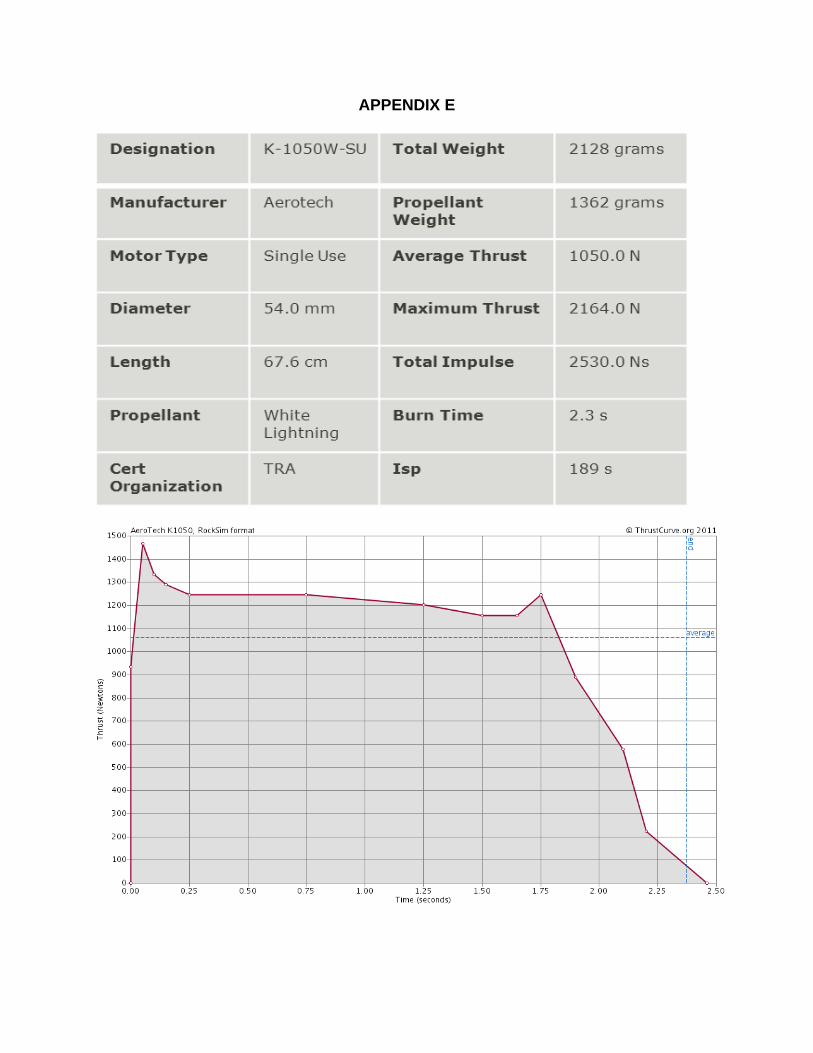
APPENDIX E

APPENDIX F
Flight Checklist
□ Pre-preparation • Remove all parachutes and set them aside • Remove the payload bay and remove the sleds assembly from inside the bay • Remove the UAV and parachute if still in the sabot
• Remove any spent engine from the rocket and the engine itself from the engine HAZARDOUS MATERIAL – SEE MSDS
casing and dispose of properly • Wash off any residue from the casing and set it aside to dry
□ Visual inspection before proceeding • Verify that all shock cords are not frayed or burned (replace if needed) • Verify that all shock cords are attached securely with quick links to the “U” bolts • Verify that all Nomex parachute shields are in good shape and not burned
through
□ Payload and recovery • Verify that both flight computers are programmed correctly (see manuals – this
should have already been completed)
• Make certain that the 4 recovery power and shunt switches are in the OFF HAZARDOUS MATERIAL – SEE MSDS
position • Remove the old 9VDC batteries and discard correctly. Replace with new
batteries and secure with tie wraps.
□ Assemble the avionics bay • Pull all switch wires to the upper (main) end of the avionics bay • Begin to insert the bulkhead and sled assembly with the recovery electronics and
payload into the lower (drogue) end of the avionics bay • Pull all 6 wires from the aft (main/drogue) bulkhead assembly through the
avionics bay to the upper end (UAV) • Connect the 6 wires from the aft (main/drogue) bulkhead assembly to the
terminal block on the upper end (UAV) – the wires are color coded • Connect the 4 wires from the UAV bulkhead end y to the terminal block on the
upper (main end) – the wires are color coded • Connect the 2 wires from the switch #1 (gray wires marked SW #1) to the
terminal block locations marked switch #1
[51]

• Similarly connect the 2 wires from each of the switches #2, #3, and #4 to their terminal block locations marked switch #2, #3, and #4 respectively
• Carefully slide the sled with the electronics into position in the avionics bay • Put the upper (main end) bulkhead in place and secure with washers and wing
nuts
□ Test the flight computers • Turn ON the Raven flight computer • Align the payload bay vertically as if it were on the launch pad • Verify the first set of beeps is 9 (indicating the battery is 9VDC) . • A low beep repeating every 2 seconds indicates an error • If there is no error, you will hear a series of 4 beeps: (1st) is the drogue, (2nd) is
the UAV, (3rd) is the Main, (4th) is unused – a low beep indicates no continuity and a high beep indicates continuity
• Short out the DROGUE pyro terminals for the Raven and verify you hear 1 high beep as the 1st beep
• Remove the short above and short out the UAV pyro terminals for the Raven and verify you hear 1 high beep as the 2nd beep
• Remove the short above and short out the MAIN pyro terminals for the Raven and verify you hear 1 high beep as the 3rd beep
• Turn OFF the Raven and turn ON the HCX CPU and PYRO • You should hear two beeps (for JP7 enabled for stage) and no warble (bad
battery) followed by a series of four sets of two beeps each (2 – 2 – 2 – 2) (this indicates the HCX is working but there is no continuity)
• Short out the DROGUE pyro terminals for the HCX and verify the series of 4 sets of beeps changes so the second is 1 beep ( 2 – 1 – 2 – 2) – this indicates continuity
• Remove the short above and short out the UAV terminals for the HCX and verify the series of 4 sets of beeps changes so the third is 1 beep ( 2 – 2 – 1 – 2) – this indicates continuity.
• Remove the short above and short out the MAIN terminals for the HCX ans verify the series of 4 sets of beeps changes so the fourth is 1 beep (2 – 2 – 2 – 1) – this indicates continuity
• Turn OFF both HCX switches
HAZARDOUS OPERATION – SEE SAFTEY PLAN
□ Prepare the TWO DROGUE parachute ejection charges • Measure the black powder for each DROGUE parachute ejection charges • Cut off an end of a rubber glove finger and pour in the black powder • Twist the wire ends of the e-match together • Insert an e-match and into the glove finger with the black powder • Compress the each glove finger and seal tightly with narrow masking tape
[52]

• Make certain the payload power switch is in the OFF position • Untwist the ends of the e-matches and connect to the DROGUE terminal blocks • Secure the glove finger/e-match/black powder so it won’t shift during launch
HAZARDOUS OPERATION – SEE SAFTEY PLAN
□ Prepare the TWO Tender Descender ejection charges • Measure the black powder for each TENDER DESCENDER main parachute
ejection charges • Twist the wire ends of the e-match together • Insert an e-match and into the Tender Descender cavity for the ejection charge
and tape in place • Remove the retainer assembly from the Tender Descender if installed • Pour the black powder into the cavity • Re-install the retainer assembly • Make certain the payload power switches are in the OFF position • Secure the wires to the Tender Descender to the shock cord so they will not be
fouled upon deployment • Untwist the ends of the e-matches and connect to the TENDER DESCENDER
terminal blocks
□ Prepare the TWO UAV parachute ejection charges • Measure the black powder for each UAV parachute ejection charges • Twist the wire ends of the e-match together • Insert an e-match and into the Tender Descender charge glove finger with the
black powder • Compress the each glove finger and seal tightly with a narrow masking tape • Make certain the payload power switches are in the OFF position • Untwist the ends of the e-matches and connect to the UAV terminal blocks • Secure the glove finger/e-match/black powder so it won’t shift during launch
□ GPS preparation – installed on the shock cord • Verify that the battery for both GPS units are fully charged by measuring it with a
voltmeter. It should measure between at least 3.85 volts and may be as high as 4.2 volts if just removed from the charger
• Connect the battery and verify the GPS has locked on to satellites (may take several minutes – verification process TBD)
• Verify the transmitter is working using the ground tracking station and Garmin display
• Slide the GPS into its protective covering • Secure the GPS and protective covering onto the shock cord (near
DROGUE/MAIN and the second near UAV).
[53]

□ Vehicle preparation – MAIN parachute • Open the MAIN parachute completely and verify the shroud lines are in good
shape and not tangled • Connect the MAIN parachute to the shock cord using the swivel • Carefully fold and roll the MAIN parachute, rolling the shroud lines ½ way around
the parachute, then reversing direction and continue rolling • Place the MAIN parachute into the Deployment bag • Roll the shock cord in a figure “8” and put the shock cord into the forward body
tube followed by the parachute in the Nomex shield verifying the parachute is completely protected by the Nomex shield
□ Vehicle preparation – DROGUE parachute • Open the DROGUE parachute completely and verify the shroud lines are in good
shape and not tangled • Connect the DROGUE parachute to the shock cord using the swivel • Carefully fold and roll the DROGUE parachute, rolling the shroud lines ½ way
around the parachute, then reversing direction and continue rolling • Place the e-match and black powder charge into the empty rear body tube • Place the DROGUE parachute into the Nomex shield and wrapping the shield
around the parachute • Roll the shock cord in a figure “8” and put the shock cord into the read body tube
(with fins) followed by the parachute in the Nomex shield verifying the parachute is completely protected by the Nomex shield
• Insert the MAIN AND DROGUE end of the payload bay into the rear body tube (with fins) and secure with four #2 nylon shear screws
□ Vehicle preparation – UAV parachute • Open the UAV parachute completely and verify the shroud lines are in good
shape and not tangled • Connect the UAV parachute to the shock cord using the swivel • Carefully fold and roll the UAV parachute, rolling the shroud lines ½ way around
the parachute, then reversing direction and continue rolling • Place the UAV parachute into the Nomex shield and wrapping the shield around
the parachute • Roll the shock cord in a figure “8” and put the shock cord into the forward body
tube followed by the parachute in the Nomex shield verifying the parachute is completely protected by the Nomex shield
□ Vehicle preparation – UAV • Verify that the two rechargeable UAV payload batteries are at full charge by
measuring with a voltmeter. They should measure at least 11.55VDC and may be as high as 12.6VDC if recently removed from the charger.
[54]

• Verify that all connectors are seated correctly • Connect the parachute and verify that the parachute release mechanism is
assembled properly and the parachute can be released • Roll the wings around the fuselage • Place the UAV into the Sabot with its parachute and close the sabot assuring that
the microswitch holds the power OFF. • Carefully route the ejection charge wiring through the channel in the sabot. • Insert the sabot into the forward body tube • Place the UAV end of the Avionics Bay into the the forward body tube and secure
with four #2 nylon shear screws
□ Vehicle preparation - propulsion • Remove the Aerotech engine from its cardboard tube and locate the igniter • Twist the bare metal ends of the igniter together and set it aside • Assure the delay is correct • If using the reloadable motor (preferred is single use) follow these instructions:
o Place the delay element on the end of the propulsion grains o Lightly grease the outside of the plastic grain and delay case and insert
into the metal casing o Insert the motor into the vehicle and secure with the motor retaining cap
• Secure the igniter to the outside of the vehicle
□ Final vehicle preparation for launch • Submit the vehicle for inspection to the range safety officer – when approved
proceed to the assigned launch rail • Side the vehicle onto the launch rail • Arm the Raven recovery electronics (one switch) and verify the following beeps
o Nine indicating the battery is at least 9 volts o Three high pitched beeps followed by one low beep indicating continuity of
the three electric matches. o If you hear a low pitched beep every 2 seconds, something is wrong.
• Turn the HCX CPU and Pyro switches on (two switches) • Turn the HCS shut switch ON – this is the final arming of the HCX and verify the
following beeps o Two low pitched beeps indicating we are not set for multiple stages or
clustering o A pause o A series of two beeps, followed by one beep, followed by one beep,
followed by two beeps, a pause, then this series repeats o If you hear any other series of beeps, there is a problem. Consult the
beep table on the next page • Untwist the bare metal ends of the igniter and insert completely into the motor
and secure
□ The vehicle can now be launched
[55]

G-Wiz HCX Flight Computer Beep Code Table
Flight Computer Status Codes Normal Status Code 1. LED turns on then off. 2. The LED turns on and the beeper gives one (JP7 OUT) or two (JP7 IN) low pitch beeps. 3. LED turns off. 4. There is a half second pause. 5. Starting with pyro port one, each pyro port reports status with either a single quick “beep” (for good continuity) or a double “beep” if the port has incomplete continuity. 6. A one second pause, and then the sequence repeats from step 2.
Low Battery 1. LED turns on, then off. 2. The LED turns on and the beeper gives one (JP7 OUT) or two (JP7 IN) low pitch beeps. 3. After a half second pause, the beeper gives a short warble. 4. LED turns off. 5. There is a half second pause. 6. Pyro port report status 7. A one second pause, and then the sequence repeats from step 2.
SD Card is Unplugged 1. The LED turns on then off. 2. Long, High pitch beep. 3. Long, low pitch beep. 4. 3/4 second delay. 5. Normal status code starts.
Power-On Self-Test Failure (POST Failure) 1. Long warble. 2. Then a half second delay. 3. 1 – 7 high pitch beeps giving a failure code. o For 1 to 4 beeps: Hardware error. Do not fly. See manual. o For 5 or 6 beeps: Reformat or replace card. See manual for more information. o For 7 beeps: The SD card is full. Reformat or replace card. 4. A 1 second pause, and then the sequence repeats.
Break Wire Error 1. Short warble. 2. A 1 second pause, and then the sequence repeats.
1.1.1.1.1.1 For Breakwire Flight
1. Power HCX off. 2. Correctly attach ends of break wire to TB2 pins3/4.
For Non-Breakwire Flight 1. Power HCX off 2. Attach a wire to TB2 pins3/4. 3. Connect HCX to FlightView 4. In Configuration window, Main tab, check Analog Input.
[56]

APPENDIX G
Budget:
[57]

[58]

APPENDIX H Timeline:

APPENDIX I AIAA OC Section Launch Safety Rules
For all rocketry activities (Youth – TARC – modified for SLI)
In an emergency, dial 911 California Poison Control Center: 1-800-222-1222
Our teams own rules completely comply with the rules stated above. The AIAA Orange County Sections rules are stated below and contain a table similar to the one included above. • The materials that will be used will be lightweight materials such as; paper, wood,
rubber, plastic, fiberglass or only when it’s necessary, metal.
• The motors that will be used will be certified commercially made rocket motors. They will not be tampered with or used for anything except recommended by the manufacturer. There will not be smoking, open flames or any other heat sources within 25 feet of the motors.
• The rocket will be launched with an electrical launch system, and with electrical motor igniters that are installed when the rocket is on the launch pad or in the designated prepping area. The launch system will have a safety interlock that is in series with the launch switch that is not activated until the rocket is ready for launch and will use a launch switch that returns to the off position when released. If the rocket has an onboard ignition systems for motors and or recovery devices, they will have safety interlock that interrupts the current path until the rocket is at the launch pad. If the ignition systems has a second battery and relay at the pad, than the batter will be disconnected while the rocket is placed on the launch pad and the igniter is connected to the launch system.
• The launcher that is used will be a stable device that provides rigid guidance until the rocket has attained a speed that ensures a stable flight , and is pointed within twenty degrees of vertical. If the wind is over five miles per hour then the launcher length that permits the rocket to attain safe velocity before separation from the launcher. A blast defector will be used to prevent the motors exhaust from hitting the ground. There will be no dry grass around each launch pad in accordance with the minimum distance table.
• If the rocket doesn’t launch, then the launchers safety interlock or disconnect the battery. Sixty seconds will be waited after the launch attempt before allowing anyone to approach the rocket. If the ignition system has a second battery and relay at the pad, that battery will be disconnected before approaching the rocket.
[60]

• The rocket will be checked for stability, a sound construction and any previous damage before it is allowed to fly. The rocket will not have a total thrust more than 40,960 N-Sec.
• The launch pad area will be checked to make sure there is no one closer to the launch pad than the minimum distance table states. The sky will be checked above the launch site to make certain there is no airplanes, helicopters or any other aircraft in the area before launching. Stating “Range is clear” and “Sky is clear” before proceeding to launch. This will be followed by a five second count down to warn anyone in the area of launch.
• The rocket will not be launched at targets into clouds or obscuring phenomena, near airplanes or on trajectories that make it directly over the heads of spectators or beyond the boundaries of the launch site and will not have a flammable or explosive payload in the rocket. The rocket will not be launched to an altitude where the horizontal visibility is less than five miles. If the wind exceeds twenty miles an hour the rocket will not be launched. The person(s) launching the rocket will comply with the Federal Aviation Administration airspace regulations when flying and will make sure our rocket does not exceed any applicable altitude limit in effect at the launch site.
• The rocket will not be launched between sunset and sunrise e.g. not in the dark.
• The rocket will be launched outdoors in an open area where trees, power lines, buildings and person(s) not involved in the launch do not represent a hazard, and that is at least as large on its smallest dimension as one-half of the maximum altitude which rockets are allowed to be flown at that site, or 1500 feet, whichever is greater.
• The launcher location will be at least 1500 feet away from any inhabited building or from any public highway on which traffic flow exceeds ten vehicles per hour, not including traffic flow related to the launch. It will also be no closer than the appropriate Minimum Personnel Distance from the accompanying table from any boundary of the launch site.
• No person(s) shall be closer to the launch of our rocket than the person who is actually flying the rocket. All spectators shall remain behind the person launching the rocket. No person(s) shall be closer to the launch that the minimum safe distance table.
• The rocket will use a recovery system so that all parts of the rocket return safety and undamaged and can be flown again. We will use only flame-resistant or fireproof recovery system wadding and heat shields in our rocket.
[61]

• No person(s) will attempt to recovery the rocket from power lines, tall trees, or other dangerous places, fly it under conditions where it is likely to recovery in spectators areas or outside the launch site, nor attempt to catch it as it approaches the ground.
Two jobs exist to ensure safety, the range safety officer and the launch control officer.
The RSO (Range Safety Officer): has the overall control responsibility for the safety of the range and can shut down the launch site if it deems necessary. They are responsible to make certain that each rocket that is flown is safe to fly before it is launched. They make certain the fins and launch lug are present and securely fastened to the body tube. They make certain that the engine is installed properly and that the recovery system is functional. Although all persons responsible for designing and building a rocket need to make certain it is safe to fly, the range safety officer has the ultimate responsibility.
The LCO (Launch Control Officer) is responsible for supervising the actual launching of the rockets and that all conditions are safe to do so. This includes making sure that the launch pads are not armed when people are close to them. Before each launch they must check for people, including spectators, in an unsafe location and nearby aircraft. For the first launch of a rocket or if the launch includes any unusual risks, the flight will be announced as a “Heads-Up” flight. This person must track each flight until the rocket returns to ground level. Again, although all persons are responsible for designing and building the rocket, need to take these same precautions, the launch control officer has the ultimate responsibility.
[62]

APPENDIX J AIAA OC Section Shop Safety Rules
For all rocketry activities (Youth – TARC – modified for SLI) In an emergency, dial 911 California Poison Control Center: 1-800-222-1222 There is always a risk when someone is handling shop tools or near someone who is handling shop tools. Great precaution should always be there. Here are the AIAA Orange County Section shop rules In general: • Keep work area clean and orderly; neatly arrange equipment and material. Put all
tools and materials back where you found them.
• If you are unsure about safe operation or process, request assistance from the program manager or mentor.
• When working with chemical, X-Acto knives, electrical tools or any tool where there is a danger of fumes or particles entering your eyes where safety glasses.
• If there is any unsafe conditions report them to your program manager or Mentor immediately. Rely on your own judgment an knowledge of safety to guide you.
• Horseplay is forbidden.
• If lifting a heavy object, lift with your legs not with your back, keep your back straight.
• Flammable liquids such as paints, solvents and thinners have to be stored in their original containers or in an approved safety cans with flamer arresters.
• Never use an air hose for cleaning or dusting yourself off. Never point it at anyone.
• If you have long hair you must tie it back or tuck it under a cap so it won’t be caught in rotating tools.
• Think through the entire tasks before starting them and never rush or take chances.
• Using heavy glues and house hold chemicals should only be done in well ventilated areas; heavy sanding, painting and use of chemicals should only be done outdoors.
• When creating documents that require work with potentially hazardous tools or operations, that section will be marked with the following:
[63]

HAZARDOUS OPERATION – SEE SAFETY PLAN
Electrical Tools • Don’t work with power tool sunless there is at least one other person present.
• Before operating any machine or equipment be certain alls safety guards are in place. The guards must be in replaced as soon as repairs or servicing on a machine has been completed and put into operation.
• Never tie down, block out or otherwise make inoperative of any type of safety device, attachment method or guard.
• Before energizing or operating any equipment verify the safety of all personnel.
• When a machine is de-energizing for the purpose of changing the setup or making a minor adjustment, turn off the machine and pull the plug. Allow the machine to come to a complete before proceeding with your task.
• Never oil, remove guards or attempt to repair machinery while it is on and in motion.
• Never use electrical equipment while standing on damp or wet surfaces or when your hands are wet.
• Wear clothes suitable for the work that you are doing. Loose clothing, neckties, rings, and watches, and even gloves create a hazard when operating tools. Long sleeves non-synthetic clothes should be worn when sparks or hot metal is present.
• Never use a rag near moving machinery.
[64]

APPENDIX K Safety Rules when using Hazardous Materials
In an emergency, dial 911 California Poison Control Center: 1-800-222-1222
In the course of completing the launch vehicle, team members will come into contact with many hazardous substances. These substances will not pose a threat to the team members as long as rules are followed when handling. Material of concern includes adhesives and paints as well as the actual materials used to build the vehicle. The manufacturer of that material knows best the hazards posed. The manufacturer and safety organizations publish MSDS for each product.
An MSDS (Material Safety Data Sheet) is there to provide the overview of how to work safely with or how to handle this chemical or material. This is compiled by the manufacture of the particular chemical. MSDS do not have a particular format but are required to have certain information per OSHA (Occupational Safety and Health Administration) 29 CFR 1910.1200. A listing of the required information can be found on this website; <http://www.osha.gov/pls/oshaweb/owadisp.show_document?p_table=standards&p_id= 10099>.
Threats to team member’s safety that must be accounted for include (see details below the table):
Risk Mitigation Impact to the body Gloves, apron, goggles Cut or puncture Gloves and Apron Chemicals – fumes and/or direct contact
Gloves, respirator, goggles
Heat/cold Gloves Harmful Dust and small particles Mask and Goggles Loud noises Earplugs
The team will keep a copy of the MSDS for all materials used in the construction of the vehicle, when an MSDS exists for that material. In addition, the following items will be present and available for use by team members whenever they are working or constructing the vehicle or payload, or whenever launching. • Safety goggles • Rubber gloves • Leather gloves • Respirators / Dust Masks • Protective aprons • Ear Plugs
[65]

Eye protection must be worn whenever there is a danger of • Dust, dirt, metal or wood chips entering the eye. This can happen when sawing,
grinding, hammering, or using power tools. When at a launch this can occur during strong winds (common at Lucerne Dry Lake)
• Chemical splashes including use of paints, solvents, or adhesives • Objects thrown (intentionally or inadvertently) or swinging into a team member
Gloves must be worn to protect the team member’s hands whenever there is a danger of contact with a hazardous material • Latex or rubber gloves for possible contact with a hazardous chemicals such as
adhesive, paint, or thinners, or even some solid materials • Leather gloves to protect against impact or getting cut or abraded (e.g. in the use
of some power tools such as grinders)
Team members will always work in a clean, well-ventilated area. Protection for a team member’s lungs (dust mask or respirator) must be used whenever: • Working with a chemical emitting fumes (e.g. paints and solvents) the team
member must wear a respirator • Working in an environment where there is dust (e.g. sanding and working with
power tools) the team member must wear a dust mask.
Body protection, such as an apron must be worn whenever there is danger of • Splashes or spills from chemicals • Possible impact from tools
Ear protection (plugs or ear muffs) must be worn whenever there are loud noises present, which includes • Using loud power tool or hammers • At launches when launching larger rocket motors
When creating documents that require work with potentially hazardous materials including chemicals, that section will be marked with the following:
HAZARDOUS MATERIAL – SEE MSDS
A sample MSDS is included in the next appendix to show what is included. As materials are identified during the research and design phases of this project, suitable MSDS for all materials used will be obtained and made available to all team members in hard copy form in the work area as well as being posted on the web site.
[66]