Preface - Sunbird · 01 Preface Thank you for choosing CPS. We are happy to provide you with...
26
Transcript of Preface - Sunbird · 01 Preface Thank you for choosing CPS. We are happy to provide you with...


01
User Manual
Preface
Thank you for choosing CPS. We are happy to provide you with first-class products and quality service.
The manual inc ludes instal lat ion, operat ion, maintenance, troubleshooting, and safety notice. As long as you follow the instruction of this manual, you will get the professional guidance and our wholehearted service.
Customer-orientation is our forever commitment. We hope this “User Manual” become your good helper in solar power generation.
Please check the latest version at http:// www.chintpower.com/en
Shanghai CHINT Power Systems Co., Ltd

02 03
User Manual User Manual
7.3 LCD Menu.........................................................................................36
7.4 State..................................................................................................38
7.5 Running-Info......................................................................................38
7.6 Statistic-Info.......................................................................................38
7.7 Current Error......................................................................................39
7.8 History Errors.....................................................................................40
7.9 Set-Param..........................................................................................40
7.10 Inverter-Info......................................................................................41
8. Product maintenance procedures ..............................................................42
9. Devanning..................................................................................................42
10. RECYCLING AND DISPOSAL.................................................................44
11. TROUBLESHOOTING..............................................................................45
12. Guaranty Service......................................................................................46
Contents
1 Information on this Manual.....................................................................04
1.1 Validity............................................................................................04
1.2 Target Group..................................................................................04
1.3 Symbols Used................................................................................04
2 Safety......................................................................................................05
2.1 Intended Use..................................................................................05
2.2 Safety Precaution...........................................................................06
3 Product Overview....................................................................................07
3.1 Product Appearance.......................................................................07
3.2 Major Characteristics......................................................................08
3.3 Datasheet.......................................................................................10
4. Installation Instructions .........................................................................16
4.1 ASSEMBLY PARTS.......................................................................16
4.2 Mounting Instructions.....................................................................17
4.3 Mounting Procedure.......................................................................18
5. Electrical Connection.............................................................................21
5.1 Safety.............................................................................................21
5.2 Overview of Connection Area........................................................21
5.3 Requirements for connection.........................................................22
5.3.1 Cable requirements: ...................................................................22
5.3.2 Circuit breaker requirements:......................................................23
5.4 AC connection procedure...............................................................24
5.5 DC connection procedure...............................................................25
5.5.1 Conditions for DC Connection.....................................................25
5.5.2 Connection Procedures by H4.....................................................266.Communication and Monitoring Setting...................................................29
6.1 Communication through RS485......................................................296.2 Communication through Ethernet RJ45..........................................306.3 Extended Wi-Fi Solution with Wi-Fi Bridge.....................................31
6.4 Communication Cable Assembly Instructions.................................31
7. LCD Operation........................................................................................34
7.1 LCD DISPLAY.................................................................................34
7.2 Startup the Inverter............................................................................35

04 05
User Manual User Manual
Danger, Warnings, cautions and Notice tell you about the dangerous conditions that can occur if you do not follow all instructions in this manual. Read and follow all warnings and cautions carefully.
2 Safety
2.1 Intended Use
The CPS inverters are PV inverter which converter the direct current of a PV array into alternating current and feed this into the electricity grid.
The inverters are designed according to the safety rules. However, improper use, alteration or modification may cause lethal hazards for the operator or third parties, or may result in damage to the units and other property. CPS is not responsible for the loss and invalidate these warranty claims.
1 Information on this Manual
1.1 Validity
This User Manual describes instructions and detailed procedures for installing, operating, maintaining, and troubleshooting of the following CPS grid-tied inverters:
√ CPS SCJ1KTL
√ CPS SCJ1.5KTL
√ CPS SCJ2KTL
√ CPS SCJ3KTL
√ CPS SCJ4KTL
√ CPS SCJ5KTL
Please keep this manual where it will be accessible at all times.
1.2 Target Group
This manual is for qualified electrically skilled person, who must strictly perform the tasks follow this manual.
1.3 Symbols Used
DANGER DANGER: indicates a hazardous situation which, if not avoided, will result
in death or serious injury.
WARNING WARNING: indicates a hazardous situation which, if not avoided, can
result in serious injury or moderate injury.
CAUTION CAUTION: indicates a hazardous condition which, if not avoided, can
result in moderate or minor injury.
NOTICE NOTICE: indicates a situation that can result in property damage, if not avoided.

06 07
User Manual User Manual
CAUTION ● The PV inverter will become hot during operation. Please don’t touch the
heat sink or peripheral surface during or shortly after operation.
● Risk of damage due to improper modifications.
● Never modify or manipulate the inverter or other components of the
system.
NOTICE ● The PV inverter is designed to feed AC power directly to the public utility
power grid Do not connect AC output of the inverter to any private AC
equipment.
3 Product Overview
3.1 Product Appearance
Type Size(mm) Weight(kg)CPS SCJ1KTL 415*331*140 11
CPS SCJ1.5KTL 415*331*140 11CPS SCJ2KTL 415*331*140 11
CPS SCJ1KTL/1.5KTL/2KTL
2.2 Safety Precaution
DANGER ● DANGER due to electrical shock and high voltage.
● Do not touch the operating component of the inverter; it might result in
burning or death.
● To prevent risk of electric shock during installation and maintenance,
please make sure that all AC and DC terminals are plugged out.
● Do not touch the surface of the inverter while the housing is wet, it might
lead to electrical shock.
● Do not stay close to the inverters while there are severe weather
conditions including storm, lighting, etc.
● Before opening the housing, the CPS inverter must be disconnected from
the Grid and PV generator; you must wait at least five minutes to let the
energy storage capacitors fully discharged after disconnecting from power
source.
WARNING ● The installation, service, recycling and disposal of the inverters must be
performed by qualified personnel only in compliance with national and local
standards and regulations.
● Any unauthorized actions including modification of product functionality
of any form may cause lethal hazard to the operator, third parties, the units
or their property. CPS is not responsible for the loss and deny these
warranty claims.
● CPS inverters must only be operated with PV generator. Do not connect
any other source of energy to the inverters.
● Be sure that the PV generator and inverter are well grounded in order to
protect properties and persons.

08 09
User Manual User Manual
Flexible:
● Multi-country configuration
● RS485 / Ethernet communication
● Wide range of DC input voltage
● IP65 for indoor and outdoor
● Flexible grid standards adaption
● DC insulation monitoring
● Ground fault protection
Reliable:
● Comprehensive protection function
● Compact design, fanless
● First-class componentType Size(mm) Weight(kg)
CPS SCJ3KTL 478*358*179 23CPS SCJ4KTL 478*358*179 23CPS SCJ5KTL 478*358*193 26
CPS SCJ3KTL/4KTL/5KTL
3.2 Major Characteristics
CPS has following characteristics which make grid-tied solar inverter “Higher Efficiency, High Reliability and High Quality.
.
High Yield:
● Dual MPP tracker, transformless design
● Wide MPPT voltage range, MPPT accuracy up to 99.9% efficiency
● Leading MPPT algorithm
● Low start-up voltage
● High conversion efficiency
● Natural convection, maintenance free
● Easy LCD operation with multi-language display
● DC switch(optional)
● Small size,light weight,easy installation

10 11
User Manual User Manual
AC Short Circuit Protection Integrated
Thermal Protection Integrated
Anti-islanding Protection AFD(Active Frequency Drift)
Interface
DC Connection MC4/H4
LCD Display LCD(16x2 Characters, Backlight) & LED(3 Lights)
Display Language Multi Language
Datalogger & Communication RS485 (Standard), Ethernet(Standard), Wi-Fi(Optional)
General Data
Topology Transformerless
Consumption at Night[W] <0.2
Consumption at Standby[W] 6
Operating Temperature Range -25°C to +60°C (45°C to 60°C with derating )
Cooling Method Natural Convection
Ambient Humidity 0% to 98% Non-condensing
Altitude Up to 2000m(without power derating)
Noise [dBA] <30
Ingress Protection IP65 (Indoor & Outdoor Installation)
Mounting Wall Bracket
Dimensions (W*H*D) [mm] 415*331*140
Weight [kg] 11
Standard Warranty [Year] 5(Standard)
Certificates
AS4777, AS3100, VDE0126-1-1/A1, G83-2, G59-2,G59-
3,C10/11,UTE C15-712-1, TF3.2.1, EN50438, IEC62116,
IEC61727,IEC61000-6-2/3,IEC62109-1/2,ABNT NBR
16149,CE,TUV
3.3 Datasheet
Type CPS SCJ1KTL CPS SCJ1.5KTL CPS SCJ2KTL
Input (DC)
Max. DC Power [W] 1200 1800 2300
Max. DC Voltage [V] 480
MPPT Voltage Range [V] 90-425 100-425
Nominal DC Voltage[V] 360
Start Voltage [V] 100 150
Min. DC Voltage [V] 80 100
Max. DC Input Current [A] 10 11 12
Number of MPPT 1
Sting(s) per MPPT 1
DC Switch Optional
Output (AC)
Rated AC Power [W] 1000 1500 2000
Max. AC Power [W] 1100 1650 2200
Rated AC Current [A] 4.3 6.5 8.7
Max. AC Current [A] 5.7 8.5 11.0
Norminal AC Voltage/Range 220V, 230V, 240V/180V-280V
Grid Frequency/Range 50Hz, 60Hz/ ±5Hz
Power Factor(cos φ) >0.99(full load)
Total Harmonic Distortion(THDi) < 2%
Feed-in Phase/Connection Phase Single Phase
Efficiency
Max. Efficiency 97.2% 97.3% 97.4%
Euro Efficiency (at 360Vdc) 96.4% 96.5% 96.7%
MPPT Accuracy >99.5%
Protection
Internal Over-voltage Protection Integrated
DC Insulation Monitoring Integrated
DCI Monitoring Integrated
GFCI Monitoring Integrated
Grid Monitoring Integrated

12 13
User Manual User Manual
GFCI Monitoring Integrated
Grid Monitoring Integrated
AC Short Circuit Protection Integrated
Thermal Protection Integrated
Anti-islanding Protection AFD(Active Frequency Drift)
Interface
DC Connection MC4/H4
LCD Display LCD(16x2 Characters, Backlight) & LED(3 Lights)
Display Language Multi Language
Datalogger & CommunicationRS485 (Standard), Ethernet(Standard), Wi-
Fi(Optional)
General Data
Topology Transformerless
Consumption at Night[W] <0.2
Consumption at Standby[W] 6
Operating Temperature Range -25°C to +60°C (45°C to 60°C with derating )
Cooling Method Natural Convection
Ambient Humidity 0% to 98% Non-condensing
Altitude Up to 2000m(without power derating)
Noise [dBA] <30
Ingress Protection IP65 (Indoor & Outdoor Installation)
Mounting Wall Bracket
Dimensions (W*H*D) [mm] 478*358*179
Weight [kg] 23
Standard Warranty [Year] 5(Standard)
Certificates
AS4777, AS3100, VDE0126-1-1/A1, G59-2, G59-3,G83-2, C10/11,UTE C15-712-1, TF3.2.1, EN50438, IEC62116, IEC61727,IEC61000-6-2/3,IEC62109-1/2,ABNT NBR 16149,CE,TUV
Remarks:
Meet the grid standard that AC current per phase not exceeding 16A.
Type CPS SCJ3KTL CPS SCJ4KTL
Input (DC)
Max. DC Power [W] 3400 4500
Max. DC Voltage [V] 580
MPPT Voltage Range [V] 120-500
Nominal DC Voltage[V] 360
Start Voltage [V] 150
Min. DC Voltage [V] 100
Max. DC Input Current [A] 30
Number of MPPT 2
Sting(s) per MPPT 1
DC Switch Optional
Output (AC)
Rated AC Power [W] 3000 4000
Max. AC Power [W] 3300 4400
Rated AC Current [A] 13.0 17.4/161
Max. AC Current [A] 15.0 20 /161
Norminal AC Voltage/Range 220V, 230V, 240V/180V-280V
Grid Frequency/Range 50Hz, 60Hz/ ±5Hz
Power Factor(cos φ) >0.99(full load)
Total Harmonic Distortion(THDi) < 2%
Feed- in Phase/Connect ion Phase
Single Phase
Efficiency
Max. Efficiency 97.6% 97.6%
Euro Efficiency (at 360Vdc) 96.8% 96.8%
MPPT Accuracy >99.5%
Protection
Internal Over-voltage Protection Integrated
DC Insulation Monitoring Integrated
DCI Monitoring Integrated

14 15
User Manual User Manual
GFCI Monitoring Integrated
Grid Monitoring Integrated
AC Short Circuit Protection Integrated
Thermal Protection Integrated
Anti-islanding Protection AFD(Active Frequency Drift)
Interface
DC Connection MC4/H4
LCD DisplayLCD(16x2 Characters, Backlight) & LED(3
Lights)
Display Language Multi Language
Datalogger & CommunicationRS485 (Standard), Ethernet(Standard), Wi-
Fi(Optional)
General Data
Topology Transformerless
Consumption at Night[W] <0.2
Consumption at Standby[W] 6
Operating Temperature Range -25°C to +60°C (45°C to 60°C with derating )
Cooling Method Natural Convection
Ambient Humidity 0% to 98% Non-condensing
Altitude Up to 2000m(without power derating)
Noise [dBA] <30
Ingress Protection IP65 (Indoor & Outdoor Installation)
Mounting Wall Bracket
Dimensions (W*H*D) [mm] 478*358*193
Weight [kg] 26
Standard Warranty [Year] 5(Standard)
Certificates
A S 4 7 7 7 , A S 3 1 0 0 , V D E 0 1 2 6 - 1 - 1 / A 1 , G59-2, G59-3,G83-2, C10/11,UTE C15-7 1 2 - 1 , T F 3 . 2 . 1 , E N 5 0 4 3 8 , I E C 6 2 11 6 , IEC61727,IEC61000-6-2/3, IEC62109-1/2,ABNT NBR 16149,CE,TUV
Type CPS SCJ5KTL
Input (DC)
Max. DC Power [W] 5200
Max. DC Voltage [V] 580
MPPT Voltage Range [V] 120-500
Nominal DC Voltage[V] 360
Start Voltage [V] 150
Min. DC Voltage [V] 100
Max. DC Input Current [A] 32
Number of MPPT 2
Sting(s) per MPPT 1
DC Switch Optional
Output (AC)
Rated AC Power [W] 5000
Max. AC Power [W] 5000
Rated AC Current [A] 21.7
Max. AC Current [A] 25
Norminal AC Voltage/Range 220V, 230V, 240V/180V-280V
Grid Frequency/Range 50Hz, 60Hz/±5Hz
Power Factor(cos φ) >0.99(full load)
Total Harmonic Distortion(THDi) < 2%
Feed-in Phase/Connection Phase Single Phase
Efficiency
Max. Efficiency 97.7%
Euro Efficiency (at 360Vdc) 97.1%
MPPT Accuracy >99.5%
Protection
Internal Over-voltage Protection Integrated
DC Insulation Monitoring Integrated
DCI Monitoring Integrated

16 17
User Manual User Manual
4.2 Mounting Instructions
● Mounting on a solid surface out door or indoor.
● Site altitude is less than 2,000m above the sea level.
● The mounting location must be clear and safely accessible at all times without the use of additional aids such as scaffolding or lifting platforms. If this is not the case, service work may be restricted.
● Mount vertically or tilted backwards by max. 15°
● The connection area must point downwards.
● Never install the inverter forward tilt, sideways tilt, horizontally or even upside down.
Install the inverter at eye level for convenience checking the LCD display and possible maintenance activities.
● Given the weight of the device, this will facilitate disassembly for service work.
● The ambient temperature should be below 45°C to ensure optimum operation. Choose locations with sufficient air exchange. Ensure additional ventilation, when necessary.
● Do not expose the inverter to direct solar irradiation as this could cause power derating due to overheating.
● In order to avoid audible vibrations in living areas, do not mount the unit on plasterboard walls or similar.
● Observe the recommended clearances to walls, other inverters or other objects, as shown in the follow diagram. That ensures sufficient heat dissipation and gives you enough space to unplug the PV Connector, communication port and operate the DC-switch.
4. Installation Instructions
4.1 ASSEMBLY PARTS
Check the delivery for completeness and for any visible external damage. Contact your specialist dealer if anything is damaged or missing.
Object Quantity DescriptionA 1 Grid-tied solar inverter
B 1 Rear panel
C
1 sets DC connector (for CPS SCJ1KTL/1.5KTL/2KTL)
2 sets DC connector (for CPS SCJ3KTL/4KTL/5KTL)
D 1 RS485 connector(if attached)
E 6 M6×50 Expansion screw
F 6 Expansion tube
G 4
M4×12 Cylinder head screw and Lock washer
(CPS SCJ1KTL/1.5KTL/2KTL)
M5×12 Cylinder head screw and Lock washer
(CPS SCJ3KTL/4KTL/5KTL)
H 1 User manual, including installation guide
I 1 Warranty card

18 19
User Manual User Manual
CPS SCJ3KTL/4KTL CPS SCJ5KTL
2) According to the marks, drill 6 holes in the wall, The aperture is 8mm and the depth is 50mm (in conformity with position marked in above picture), and then place expansion tubes in the holes using a rubber hammer.
3) Mount the rear panel.Wring six screws into the expansion tubes and tightly mount the rear panel on the wall.
4.3 Mounting Procedure
Use the rear panel in the package as a drilling template and mark the position of the holes, as illustrated below.
CPS SCJ1KTL/1.5KTL/2KTL

20 21
User Manual User Manual
5. Electrical Connection
5.1 Safety
NOTICE ● Internal components of the inverter can be damaged by Electrical
discharge, take measurement to avoid Electrical discharge during relevant
operation.Earth yourself before touching any components.
5.2 Overview of Connection Area
CPS SCJ1KTL/1.5KTL/2KTL
CPS SCJ3KTL/4KTL/5KTL
4) Carefully attach the inverter to the rear panel according to the position of the screws. Make sure the backside of the inverter is closely against the rear panel. When two people transport the inverter, make sure each one use the hand grip in right position as illustrated in the picture.
5) Pay attention to the four notches cut in both flanks of heat sink (as illustrated in above picture), which should be placed in corresponding hooks from the rear panel. Make sure that the heat sink and the rear panel are buckled together and the inverter is tightly attached to the rear panel. And tighten the screws with 0.59N.m torque.
6) Please carefully check the accessories and original carton to make sure during the installation every necessary part is used and nothing is missing.
22 23
User Manual User Manual
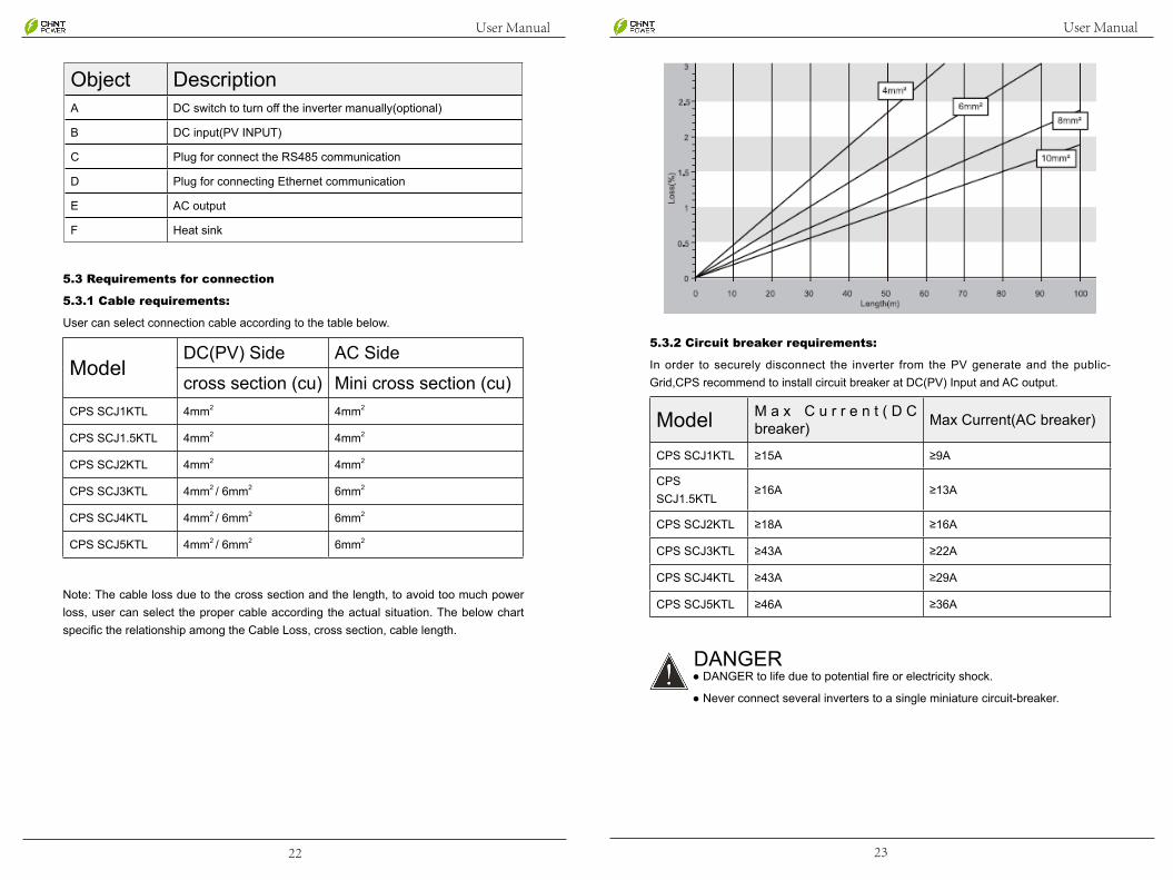
5.3.2 Circuit breaker requirements:
In order to securely disconnect the inverter from the PV generate and the public-Grid,CPS recommend to install circuit breaker at DC(PV) Input and AC output.
Model M a x C u r r e n t ( D C breaker) Max Current(AC breaker)
CPS SCJ1KTL ≥15A ≥9A
CPS SCJ1.5KTL
≥16A ≥13A
CPS SCJ2KTL ≥18A ≥16A
CPS SCJ3KTL ≥43A ≥22A
CPS SCJ4KTL ≥43A ≥29A
CPS SCJ5KTL ≥46A ≥36A
DANGER ● DANGER to life due to potential fire or electricity shock.
● Never connect several inverters to a single miniature circuit-breaker.
Object DescriptionA DC switch to turn off the inverter manually(optional)
B DC input(PV INPUT)
C Plug for connect the RS485 communication
D Plug for connecting Ethernet communication
E AC output
F Heat sink
5.3 Requirements for connection
5.3.1 Cable requirements:
User can select connection cable according to the table below.
ModelDC(PV) Side AC Side
cross section (cu) Mini cross section (cu)CPS SCJ1KTL 4mm2 4mm2
CPS SCJ1.5KTL 4mm2 4mm2
CPS SCJ2KTL 4mm2 4mm2
CPS SCJ3KTL 4mm2 / 6mm2 6mm2
CPS SCJ4KTL 4mm2 / 6mm2 6mm2
CPS SCJ5KTL 4mm2 / 6mm2 6mm2
Note: The cable loss due to the cross section and the length, to avoid too much power loss, user can select the proper cable according the actual situation. The below chart specific the relationship among the Cable Loss, cross section, cable length.

24 25
User Manual User Manual
4) Use a screw driver and loose the three screws at the side of the straight plug. Then insert the stripped N, L and PE cable according to the corresponding position and fully tighten the screws.
NOTE: ● The PE conductor must be 5 mm longer than the L
and N conductor.
● L and N must not be swapped. Reverse connection
may cause the inverter can not work normally or
even damage the inverter.
5) Aim the terminals on the straight plug to the holes of the grommet, and then compress them together.
5.5 DC connection procedure
5.5.1 Conditions for DC Connection
CPS SCJ1KTL, CPS SCJ1KTL, CPS SCJ2KTL Single MPPT, one DC input connection set per MPPT.
CPS SCJ3KTL, CPS SCJ4KTL, CPS SCJ5KTL:Dual MPPT(PV1 and PV2), one DC input connection set per MPPT. The default setting of Double MPPT is independent mode.So you can install two Solar panels that are in different numbers or directions .The system is more flexible.
5.4 AC connection procedure
1) Strip the cable with the length 0.276 inches (9/32″) - (7mm) and please be careful NOT to nick conductors.
2) Screw off and separate each component of AC connector as follows.
3) Pass the cable through each component from right to the left as follows.
Tighten the screws with 3.0N·m torque.

26 27
User Manual User Manual
3) Insert stripped cable into contact barrel and insure all conductor strands are captured in the contact barrel and the conductors are visible in the contact barrel observation hole.
Barrel observation hole Conductor should be visible
Barrel observation hole Conductor should be visible
4) Crimp contact barrel by using the hex crimping die. Ensure it is fixed.
Crimped pin contact
Crimped socket contact
Remove guide:
1) Take out the H4 unlocking tool.
2) Using the tool aim at the two holes of the H4 connector.
5.5.2 Connection Procedures by H4:
Connect the PV generator and the inverter using H4 connectors, as follows.
Note: If using MC4 connector, the operating procedures are similar to that of H4 connector.
The DC connectors come pre-assembled and the caps are loose. The whole connector will include the male side and female side as showed below:
Male side connector (M) Female side connector (F)
Assembly Instructions:
1) Strip the cable with the length of 0.276 inches (9/32”)-(7mm) and please be careful NOT to nick conductors.
2) Use specified strip tool in this step. Adjust the strip stopper and put the cable in corresponding notch to strip the length of 7mm.

28 29
User Manual User Manual
6.Communication and Monitoring Setting
CPS offers 2 standard communication interfaces for CPS solar inverters: RS485 and Ethernet RJ45. All the CPS products involved in the solar monitoring system are:
CPS Datalogger data logger for local monitoring and maintenance of large solar power plants.
CPS web portal: free monitoring application through web, IPhone, IPAD and Android App. Internet access must be ensured for the inverter network configuration before CPS Web Portal service registration.
CPS web Server: the local web monitoring application through web browser built in all CPS inverters.
For more details, please refer to CPS Monitoring Solution through http://www.chintpower.com/en
6.1 Communication through RS485
RS485 is used for multi-point communication.
Note:
1) RS485 can communicate and monitor up to 32 inverters.
2) The MAX. length of the communication cable should not exceed 1000m.
CPS Datalogger Multi-point Monitoring
PC+ CPS Datalogger Multi-point Monitoring
3) Force the tool into the holes.
4) Pull the tool out when it is completely inserted into the H4 connector.
Cable Requirements:Cable Size Cable pull – out force requirement
4 mm² Min. 400N.m(90Lbs)6 mm² Min.450N.m(100Lbs)10 mm² Min.500N.m(110Lbs)
1) Insert contact cable assembly into back of male and female connector. A“click” should be heard or felt when the contact cable assembly is seated correctly.
2) Wrest the cap by using the torque of 2.6~2.9N·m.
3) After wrested the cap tightly, align the 2 half connectors and mate them together by hand until a “click” is heard or felt.

30 31
User Manual User Manual
6.3 Extended Wi-Fi Solution with Wi-Fi Bridge
We choose EW-7228APn of EDIMAX as the Wi-Fi bridge reference
All the Wi-Fi bridge or repeater(For example, Edimax EW-7228APn) which has Ethernet RJ45 port can connect to CPS with RJ45 cable and to Wi-Fi router wirelessly.(For details please refer to the document “CPS Monitoring Solution with Integrated RJ45 Plus Wi-Fi Bridge.pdf” from http://www.chintpower.com/en
6.4 Communication Cable Assembly Instructions
All cables mentioned in this Manual are 5E Shielded Cable, as shown in below picture.
Terminals
According to different communication solutions, users may need at least one of the below terminals. They are 3Pin Connector and RJ45 Plug as shown in below picture.
Connection Procedures
1) Inverter 1 connects to Inverter 2 through RS485 cable; Inverter 2 connects to Inverter 3 through RS485 cable. In the same way to connect all inverters.
2) Inverter 1 connects to CPS Datalogger through RS485-L cable.
3) Connect CPS Datalogger to PC through Router.
4) Open the internal Web Server of CPS Datalogger for plant and inverter monitoring.
6.2 Communication through Ethernet RJ45
When users choose Ethernet communication solution, users can access to Inverter real-time information through Inverter IP address, or through CPS Logger IP address. The inverter is configured enable DHCP as default, and the router will automatically allocate IP address.

32 33
User Manual User Manual
RS485-L Cable
RS485-L cable is used to connect Inverter and CPS Datalogger when inverters are monitored via RS485. One end of the cable uses 3Pin Connector, and the other end uses RJ45 Plug. Connection is shown in below:
Wire Connector No. RJ45 plug's Pin NO
Blue & White 1 5
Blue 2 4
RJ45 Cable
RJ45 cable is the standard cable for Ethernet communication. Users can buy this cable in stores, or can assemble RJ45 cable as below:
Each end of the cable must be connected to RJ45 Plug according to below table and make sure they are fixed well.
RJ45 plug's Pin NO
One RJ45 plug's Wire colorOne RJ45 plug's Wire color
1 White & Green White & Orange
2 Green Orange
3 White & Orange White & Green
4 Blue Blue
5 White & Blue White & Blue
6 Orange Green
7 White & Brown White & Brown
8 Brown Brown
Tools:
When making a communication cable, the professional tools shown in below are needed.
RS485 Cable
When using RS485 for monitoring, users need RS485 cables to connect between inverters for multi-point monitoring. In this case, we provide connection by using the 3Pin connectors.
Each cable should be connected to the connectors according to below table.
Connector No. Color
1 Blue & White
2 Blue
3 Metal shielded wire

34 35
User Manual User Manual
7.2 Startup the Inverter
CPS Innverter can be configured for various countries, if it is the first time the inverter starts up after installation, LCD will quickly switch to and stay at the country setting interface. Only the inverter is set to comply with a certain country, it will work and display normally. Otherwise, LCD will always stay at the “Please Set The country First” interface.
There are 32 countries for choosing until March 2014.
1 Australia 17 China
2 Austria 18 Thailand
3 Belgium 19 Default
4 Brazil 20 Hungary
5 Denmark 21 Morocco
6 Finland 22 Germany
7 France 23 Israel
8 Luxembourg 24 Greece
9 Netherland 25 Malaysia
10 Norway 26 New Zealand
11 Poland 27 Spain
12 Sweden 28 Croatia
13 Switzerland 29 Uruguay
14 UK 30 Czech Republic
15 Italy 31 Sri lanka
16 Portugal 32 Japan
Note: If you can’t find the country you want, please directly select ‘Default’.Default mode represent the VDE 0126-1-1.
After Country configuration, Inverter will have a self-check when starting up. If no malfunction is found and grid connection requirement is met, inverter LCD will go to the countdown screen.
7. LCD Operation
7.1 LCD DISPLAY
Object Description
APOWER:
Yellow light shines when the inverter is energized.
B
FAULT:
Red light shines when fault occurs and automatically goes out when the fault is removed.
CRUN:
Green light flashes when the inverter runs good.
D /ESC
E /ENT
FLCD screen for viewing the running data & recorded information, and setting parameters.

36 37
User Manual User Manual
7.3 LCD Menu
(Take CPS SCJ3KTL as an example)
SN:1012391441009D
PC:101010239

38 39
User Manual User Manual
Data name Explanation UnitE-Today The generated energy of current day kWh
E-MonthTotal generated energy of the month and the daily
generated energy of current monthkWh
E-YearTotal generated energy of current year and the monthly generated energy of current year.
kWh
E-TotalThe total energy generated by the inverter and total generated energy of the year.
KWh
T-Today The operating time of current day hT-Total Total hours of operation time h
7.7 Current Error
If something is wrong with inverter, the Fault LED will be on, meanwhile we can check the details from LCD.
Please go to Chapter 9 “TROUBLESHOOTING” for further information
Error Explanation Type of ErrorConsistent Err S Consistent Error (Slave)
Error
Grid Volt Err S Grid Voltage Error (Slave)Grid Freq Err S Grid Frequency Error (Slave)Grid Loss Err S Grid Loss Error (Slave)Bus Over Volt S Bus Over voltage(Slave)GFCI Err S GFCI Error (Slave)Over-TEMP. S Over-temperature (Slave)PV Over Volt S PV-Over voltage (Slave)AC Over Current M AC-Over current (Master*)Isolation Err M Isolation Error (Master)Grid Volt Err M Grid Voltage Error (Master)Grid Freq Err M Grid Frequency Error (Master)V-Grid 10m Err M Grid Voltage 10min Error(Master)DCI Err M DCI Error(Master)GFCI Err M GFCI Error (Master)Over-TEMP. M Over-temperature (Master)Other Err S Other Error (Slave)
Permanent
Error
Int. Comm Err S Internal Communication Error(Slave)Curr Sensor Err S Current Sensor Error (Slave)2.5V Ref Err S 2.5V Ref Error (Slave)Other Err M Other Error (Master)Curr Sensor Err M Current Sensor Error (Master)GFCI Dvc Err M GFCI Device Error (Master)Int. Comm Err M Internal Communication Error(Master)E2PROM R/W Err M E2PROM R/W Error (Master)2.5V Ref Err M 2.5V Ref Error (Master)DCI Device Err M DCI Device Error(Master)Relay Err M Relay Error (Master)
7.4 State
If the country has been set, the LCD will show the machine type when inverter is started up, then it automatically displays inverter operation status: Normal, Wait, Shutdown, Fault, P-Fault, Update.
Status Explanation
Normal The inverter in normal (function) operation
Wait The inverter in stand-by state
Shutdown The inverter stops working
Fault A fault occurs during operation
P-faultA fault occurs repeatedly and has reached a certain times during Operation
Update The state of updating firmware
Press “ENT” to enter the second level menus.
7.5 Running-Info
“Running-Info” includes real time system data. All the data are explained inthe following Table.
Electrical Real Time Data (Running-Info)
Data name Explanation UnitP-ac Output AC power WV-grid Grid voltage VI-grid Output AC Current AF-grid Grid frequency HzV-PV1 DC Voltage of PV array1 VI-PV1 DC Current of PV array1 AV-PV2 DC Voltage of PV array2 VI-PV2 DC Current of PV array2 ATemp. The temperature of the inverter ℃
7.6 Statistic-Info
“Statistic-Info” includes some statistics information. All the data are explained in the following table.
> Running-Info
Statistic-Info
>Current Error
History Errors
> Set-Param
Inverter-Info

40 41
User Manual User Manual
Ethernet :
The inverter can get an IP address from router by using DHCP (Dynamic host
configuration protocol) or user can set a fixed IP.
If user manually set an IP address, the inverter will use it all the time until reset a new one or use DHCP model to get an IP addr.
Change Password:
User can change the password by the “Change Password” menu.
Clear Errors
Be caution that this operation will clear up all the history error records.
If user wants to clear up the history error records, move the cursor and press ENT to enter the sub-items, press ENT to confirm the setting when the below menu occurs. Press ESC or ENT to exit when “Set Complete!” appears.
Clear Energy:
Be caution that this operation will clear up the generated energy data of E-Today
、E-Month、E-Year、E-total、T-Today、T-Total etc. If user wants to clear up the generated energy record, move the cursor to “clear energy” and press “ENT” to enter the sub-items, press “ENT” to confirm the setting when the below menu occurs. Press ESC or ENT to exit when “Set complete!” appears.
Factory Setting:
Note: This operation will erase all history data record, such as generated energy, error logs etc. And the password and Grid Compliance will be set back to default
settings.
Enter “Factory Setting” menu to enter the password, the system will required
users to re-confirm “Factory Setting”. Press “ENT” button to confirm. You can
see “Set complete” to finished the “ Factory setting” and press “ESC” or “ENT”to exit the “ Set complete”
7.10 Inverter-Info
User can read the inverter detailed machine information:
User can enter the corresponding sub-menu to see the detailed information .
Enter the “Firmware Ver” , it will show the firmware version of master control unit, slave
> Machine Type
Grid Compliance> Firmware Ver
>SN code
Product Code
7.8 History Errors
When enter the History Errors menu if one or more error had happened, we can see the error occurred time. Move the cursor to the desired error time, press ENT to see the detailed error information (see the above table)
>11/11/09 12:00 11/11/07 15:12
7.9 Set-Param
Note: Every parameter is effective after the below menus have been confirmed.
Date :
This setting includes year, month and date”. Press “▼ ” or “▲ ” button to
choose one of the items: year/ month/date, press ENT to make the cursor “^”
point to the selected item. Then press “▼” or “▲” button to set the parameter.
Press ENT to confirm this item setting, then it automatically points to the next
item setting. Repeat the operation steps to set other item.
When the three items have been set, “Are you sure to set it?” will appear; press
ENT to confirm it. Then press ESC or ENT to exit when “Set Complete!”
appears.
Time :
This setting includes “hour, minute and second”.
Please refer to the operation steps of “Date Setting”.
Grid Compliance:
The Gird Compliance may be different in the different countries. If the chosen
country of “Grid Compliance” is incorrect, we can modify it.
Set complete!Are you sure to set it?
Date: 2011/10/31
Time:15:48:28

42 43
User Manual User Manual
2、Hold the inveter with two hands, and then push up the machine.
Hand position
Hand position
control unit, display board (the firmware version will vary when it is updated)
8. Product maintenance procedures
In order to reduce the risk, inverter should not be exposed in harsh environment such as rainy day,frosting day,science, in fog,greasy and large amounts of dust;Do not install the inverter in the sealed space;Don’t cover and block the vents, or the inverter will be damaged by the overheating.
The inverter should avoid fire and lightning strikes. Any unqualified wire may damage the inverter.
Because the inverter itself can produce arc components, so it can not be installed in the flammable, explosive environment where including batteries and inflammable materials and without protection equipment side that including: the component system of gasoline engine, fuel cylinder or other in the fuel side.
You should keep the inverter in the proper preventive maintenance and maintenance. Using wet cloth to clearn the external of the nverter and stains. At the same time you should tight the DC input terminal screws; Clean the dust of the inverter surface by using a high pressure gun .
You should close the inverter before cleaning and maintaining the machine.
9. Devanning
1、Unscrew the screws that on the four sides of the rear panel.

44 45
User Manual User Manual
3、When the machine is pushed to the top of the screen, you can remove the machine from the front.
10. RECYCLING AND DISPOSAL
WARNING This device shall not be disposed of in residential waste.
To comply with European Directive 2002/96/EC on waste Electrical and
Electronic Equipment and its implementation as national law, electrical
equipment that has reached the end of its life must be collected separately and
returned to an approved recycling facility. Any device that you no longer
required must be returned to your dealer or you must find an approved
collection and recycling facility in your area.
Ignoring this EU Directive may have severe affects on the environment and
your health.
11. TROUBLESHOOTING
For safety, two micro control CPU is needed, Master CPU and Slave CPU. In the table below “M” represent Master CPU, “S” represent Slave CPU.
Error Code Message Description
01 Consistent Err S Different value between S and M
02 Grid Voltage Err SThe grid frequency at the inverter is less or more than the permissible value. Due to legal requirements, the inverter switches automatically off while the error state is present.
03 Grid Freq Err SThe grid frequency at the inverter is less or more than the permissible value. Due to legal requirements, the inverter switches automatically off while the error state is present.
04 Grid Loss Err S The Grid is disconnected05 Bus Over Volt S Bus Voltage is higher than the permissible value.06 GFCI Err S Ground leakage current is higher than permissible value.
07 Over-TEMP. S The internal temperature of inverter is higher than the permissible value.
08 PV Over Volt S The PV voltage is higher than the permissible value.09 AC Over Current M The AC current is higher than the permissible value.
10 Isolation Err M The resistace between PV+ or PV- to Ground is lower than permissible value.
11 Grid Volt Err M The grid frequency at the inverter is less or more than the permissible value. Due to legal requirements, the inverter switches automatically off while the error state is present.
12 Grid Freq Err M13 V-Grid 10m Err M14 DCI Err M The DC injection to grid is higher than permissible value.15 GFCI Err M Ground leakage current is higher than permissible value.
16 Over-TEMP. M The internal temperature of inverter is higher than the permissible value.
17 Other Err S Other problem.
18 Int. Comm Err S Communication between Control board and display board have problem.
19 Reserved Reserved20 Reserved Reserved21 Reserved Reserved22 Other Err M Other problem.23 Curr Sensor Err M Current sensor have problem.24 GFCI Dvc Err M Ground leakage current is higher than permissible value.
25 Int. Comm Err M Communication between Control board and display board have problem.
26 E2PROM R/W Err M E2PROM can not be written and read27 2.5V Ref Err M Reference voltage have problem28 DCI Device Err M The DC injection to grid is higher than permissible value.29 Relay Err M Relay have problem.30 VGrid Consist S Different grid voltage value between S and M31 FGrid Consist S Different grid frequency value between S and M32 DCI Consist S Different DC injection value between S and M33 GFCI Consist S Different leakage current value between S and M

46 47
User Manual User Manual
12. Guaranty Service
Please refer to the warranty card.
CPS grants a standard warranty period of 66 months (5.5 years) for the Series inverters starting from the date of shipment from CPS factory or 60 months (5years) starting from the date of purchased invoice marked (whichever is longer).
If you need after-sales service, please contact the agent or manufacturer. They will provide service for you. For more details, please refer to the warranty card.
ABBREVIATION
LCD Liquid Crystal Display
LED Light Emitting Diode
MPPT Maximum Power Point Tracking
PV Photovoltaic
GFCI Ground Fault Current Interrupter
Vdc Voltage at the DC side
Vac Voltage at the AC side
Vmpp Voltage at the Maximum Power Point
Impp Amperage at Maximum Power Point
Voc Open Circuit Voltage
Isc Short Circuit Current
AC Alternating Current (Form of electricity supplied by Utility Company)
DC Direct Current (Form of electricity generated by PV modules)
VDE 0126-1-1 German standards for establishing suitability for Grid
Connection of the Inverter.
DC Switch Switch in the DC Circuit. Disconnects DC source from Inverter. May be integrated or external to Inverter.
If you have technical problems concerning our products, contact the CPS Service line.
Shanghai CHINT Power Systems Co., Ltd.
Block 4, 3255 Sixian Road,SongJiang District, Shanghai 201614, P.R. China
TEL : +86-021-3779-1222
FAX : +86-021-3779-1222-6003
Chint Power Systems Global Customer Service Center
Block 5, 3255 Sixian Road, SongJiang District, Shanghai 201614, P.R. China
Hotline : +86-021-3779-1222 - 6300
FAX : +86-021-3779-1222-6016
Mail: [email protected]
Custemer Service Center (Cooperation Service Providers) in Europe:
Hotline +49 (0)40 254 000 927
Stephanstraße 4-8, 76316, Malsch, Germany
Customer Service Center in North America
Hotline: +1-972 761 3992
700 International Pkwy, Suite 102, Richardson, TX 75081
Sales Hotline: 021-3779-1222-6800E-mail: [email protected]

Block 4, 3255 Sixian Road,SongJiang District,
Shanghai 201614, P.R. China
TEL : +86-021-3779-1222
FAX : +86-021-3779-1222-6003
Shanghai CHINT Power Systems Co., Ltd.