Predictive Engineering Tools for Injection-Molded … Engineering Tools for Injection-Molded ......
15
PNNL-24834 Ba Nghiep Nguyen, Leonard S. Fifield Pacific Northwest National Laboratory, Richland, WA 99354 Eric J. Wollan, Dale Roland PlastiComp, Inc., Winona, MN 55987 Umesh N. Gandhi Toyota Research Institute North America, Ann Arbor, MI 48105 Steven Mori MAGNA Exteriors and Interiors Corporation, Aurora, Ontario, Canada Gregory Lambert, Donald G. Baird Virginia Polytechnic and State University, Blacksburg, Virginia 24061 Jin Wang, Franco Costa Autodesk, Inc., Ithaca, NY 14850 Charles L. Tucker III University of Illinois at Urbana-Champaign, Urbana, IL 61801 Project period: From October 1 st 2012 to September 30 th , 2016 Reporting period end date: September 30 th , 2015 Quarterly report submitted to: Aaron Yocum, National Energy Technology Laboratory, Morgantown, WV 26507 Predictive Engineering Tools for Injection-Molded Long-Carbon-Fiber Thermoplastic Composites October 2015
Transcript of Predictive Engineering Tools for Injection-Molded … Engineering Tools for Injection-Molded ......
PNNL-24834
Ba Nghiep Nguyen, Leonard S. Fifield Pacific Northwest National Laboratory, Richland, WA 99354
Eric J. Wollan, Dale Roland
PlastiComp, Inc., Winona, MN 55987
Umesh N. Gandhi
Toyota Research Institute North America, Ann Arbor, MI 48105
Steven Mori
MAGNA Exteriors and Interiors Corporation, Aurora, Ontario, Canada
Gregory Lambert, Donald G. Baird
Virginia Polytechnic and State University, Blacksburg, Virginia 24061
Jin Wang, Franco Costa
Autodesk, Inc., Ithaca, NY 14850
Charles L. Tucker III
University of Illinois at Urbana-Champaign, Urbana, IL 61801
Project period: From October 1st 2012 to September 30th, 2016 Reporting period end date: September 30th, 2015 Quarterly report submitted to: Aaron Yocum, National Energy Technology Laboratory, Morgantown, WV 26507
Predictive Engineering Tools for Injection-Molded Long-Carbon-Fiber
Thermoplastic Composites
October 2015

PNNL-24834
PNNL-24834
Predictive Engineering Tools for Injection-molded Long-Carbon-Fiber Thermoplastic
Composites
Ba Nghiep Nguyen, Leonard S. Fifield
Pacific Northwest National Laboratory, Richland, WA 99354
Eric J. Wollan, Dale Roland
PlastiComp, Inc., Winona, MN 55987
Umesh N. Gandhi
Toyota Research Institute North America, Ann Arbor, MI 48105
Steven Mori
MAGNA Exteriors and Interiors Corporation, Aurora, Ontario, Canada
Gregory Lambert, Donald G. Baird
Virginia Polytechnic and State University, Blacksburg, Virginia 24061
Jin Wang, Franco Costa
Autodesk, Inc., Ithaca, NY 14850
Charles L. Tucker III
University of Illinois at Urbana-Champaign, Urbana, IL 61801
October 2015
Project period: From October 1st 2012 to September 30th, 2016
Reporting period end date: September 30th
, 2015
Quarterly report submitted to:
Aaron Yocum, National Energy Technology Laboratory, Morgantown, WV 26507
Prepared for
the U.S. Department of Energy
under Contract DE-AC05-76RL01830
Pacific Northwest National Laboratory
Richland, Washington 99352
PNNL-24834
The objective of this project is to advance predictive engineering (PE) tools to accurately predict fiber
orientation and length distributions in injection-molded long-carbon fiber thermoplastic composites for
optimum design of automotive structures using these materials to meet weight and cost reduction
requirements defined in Table 2 of DE-FOA-0000648 (Area of Interest 1).
Background
This project proposes to integrate, optimize and validate the fiber orientation and length distribution
models previously developed and implemented in the Autodesk Simulation Moldflow Insight (ASMI)
package for injection-molded long-carbon-fiber thermoplastic composites into a cohesive prediction
capability. In our previous US Department of Energy (DOE) funded project, entitled “Engineering
Property Prediction Tools for Tailored Polymer Composite Structures,” Pacific Northwest National
Laboratory (PNNL), with the University of Illinois and Autodesk, Inc., developed a unique assembly of
computational algorithms providing state-of-the-art process and constitutive models that enhance the
capabilities of commercial software packages to predict fiber orientation and length distributions as well
as subsequent mechanical properties of injection-molded long-fiber thermoplastic (LFT) composites.
These predictive capabilities were validated using fiber analysis data generated at Oak Ridge National
Laboratory on two-dimensional (2D) structures consisting of edge-gated plaques and center-gated disks
injection-molded from long-glass-fiber/polypropylene (PP) and long-glass-fiber/polyamide 6,6 (PA66)
pellets. The present effort aims at rendering the developed models more robust and efficient to automotive
industry part design to enable weight savings and cost reduction. This ultimate goal will be achieved by
optimizing the developed models, improving and integrating their implementations in ASMI, and
validating them for a complex three-dimensional (3D) long-carbon fiber (LCF) thermoplastic automotive
part. Both PP and PA66 are used for the resin matrices. Local fiber orientation and length distributions at
the key regions on the part are measured for the model validation based on a 15% accuracy criterion. The
project outcome will be the ASMI package enhanced with computational capabilities to accurately predict
fiber orientation and length distributions in automotive parts designed with long-carbon fiber
thermoplastics.
3. Accomplishments
During the last quarter of FY 2015, the following technical progress has been made toward project
milestones:
1) PlastiComp used the PlastiComp direct in-line (D-LFT) Pushtrusion system to injection mold 40
30wt% LCF/PP complex parts with ribs, 40 30wt% LCF/PP complex parts without ribs, 10 30wt%
LCF/PA66 complex parts with ribs, and 35 30wt% LCF/PA66 complex parts without ribs. In
addition, purge materials from the injection molding nozzle were obtained for fiber length analysis,
and molding parameters were sent to PNNL for process modeling.
2) Magna cut samples at four selected locations (named A, B, C and D) from the non-ribbed Magna-
molded complex parts based on a plan discussed with PNNL and the team and shipped these samples
to Virginia Tech for fiber orientation and length measurements.
3) Virginia Tech started fiber orientation and length measurements for the samples taken from the
complex parts using Virginia Tech’s established procedure.
4) PNNL and Autodesk built ASMI models for the complex parts with and without ribs, reviewed
process datasheets and performed preliminary analyses of these complex parts using the actual
molding parameters received from Magna and PlastiComp to compare predicted to experimental
mold filling patterns.
5) Autodesk assisted PNNL in developing the workflow to use Moldflow fiber orientation and length
results in ABAQUS® simulations.
PNNL-24834
6) Autodesk advised the team on the practicality and difficulty of material viscosity characterization
from the D-LFT process.
7) PNNL developed a procedure to import fiber orientation and length results from a 3D ASMI analysis
to a 3D ABAQUS® model for structural analyses of the complex part for later weight reduction study.
8) Toyota built a finite element model for the complex parts subjected to torsion loading.
9) PNNL built the 3D ABAQUS® model of the complex ribbed part subjected to 3-point bending.
10) University of Illinois (Prof. C.L. Tucker) advised the team on fiber orientation and fiber length
measurement options, modeling issues as well as interpretation of data.
4. Progress and Status
4.1 Molding the Complex Parts with and without Ribs (PlastiComp)
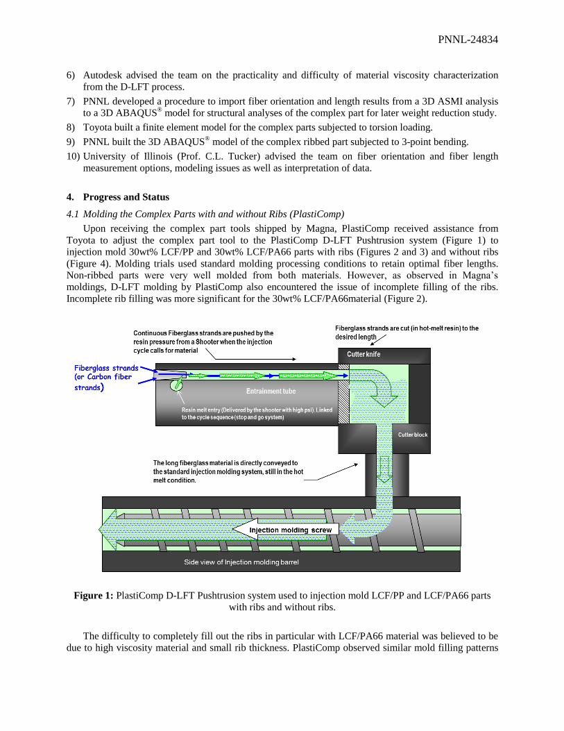
Upon receiving the complex part tools shipped by Magna, PlastiComp received assistance from
Toyota to adjust the complex part tool to the PlastiComp D-LFT Pushtrusion system (Figure 1) to
injection mold 30wt% LCF/PP and 30wt% LCF/PA66 parts with ribs (Figures 2 and 3) and without ribs
(Figure 4). Molding trials used standard molding processing conditions to retain optimal fiber lengths.
Non-ribbed parts were very well molded from both materials. However, as observed in Magna’s
moldings, D-LFT molding by PlastiComp also encountered the issue of incomplete filling of the ribs.
Incomplete rib filling was more significant for the 30wt% LCF/PA66material (Figure 2).
Figure 1: PlastiComp D-LFT Pushtrusion system used to injection mold LCF/PP and LCF/PA66 parts
with ribs and without ribs.
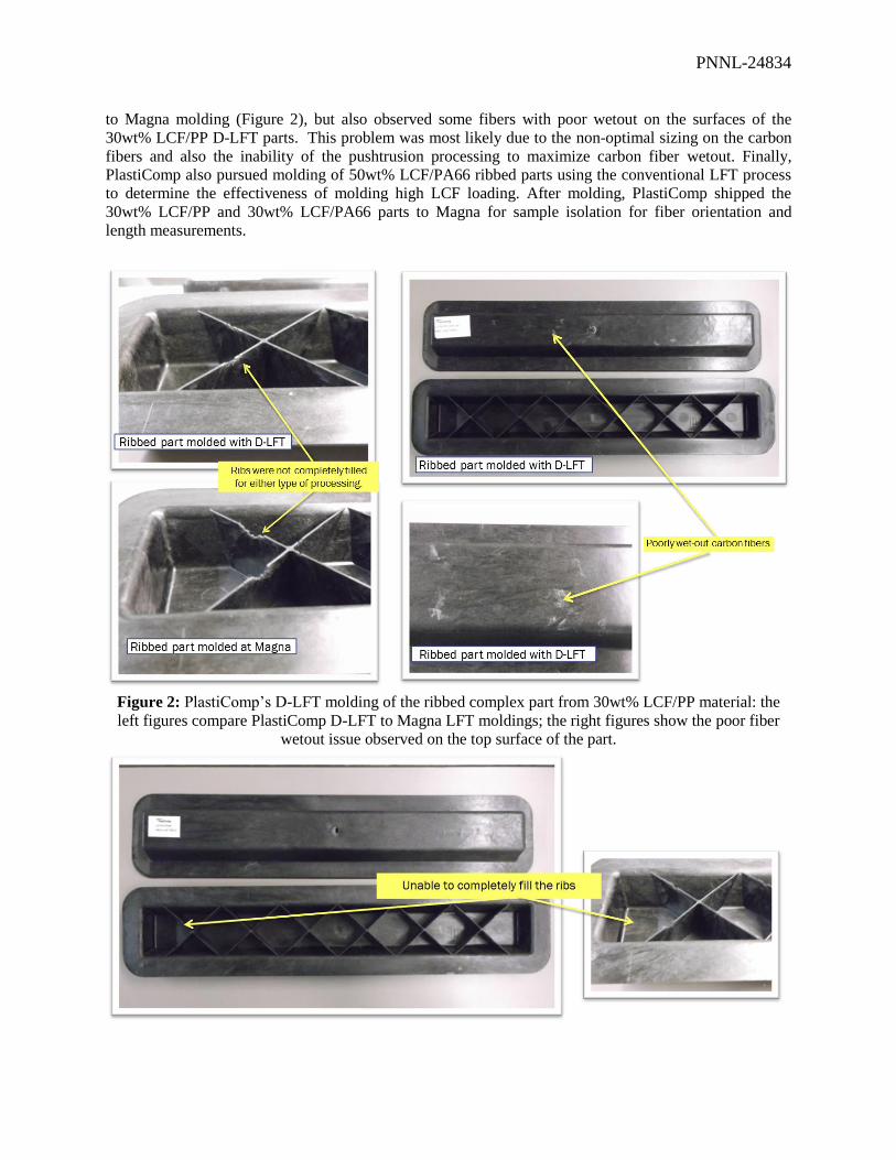
The difficulty to completely fill out the ribs in particular with LCF/PA66 material was believed to be
due to high viscosity material and small rib thickness. PlastiComp observed similar mold filling patterns
PNNL-24834
to Magna molding (Figure 2), but also observed some fibers with poor wetout on the surfaces of the
30wt% LCF/PP D-LFT parts. This problem was most likely due to the non-optimal sizing on the carbon
fibers and also the inability of the pushtrusion processing to maximize carbon fiber wetout. Finally,
PlastiComp also pursued molding of 50wt% LCF/PA66 ribbed parts using the conventional LFT process
to determine the effectiveness of molding high LCF loading. After molding, PlastiComp shipped the
30wt% LCF/PP and 30wt% LCF/PA66 parts to Magna for sample isolation for fiber orientation and
length measurements.
Figure 2: PlastiComp’s D-LFT molding of the ribbed complex part from 30wt% LCF/PP material: the
left figures compare PlastiComp D-LFT to Magna LFT moldings; the right figures show the poor fiber
wetout issue observed on the top surface of the part.
PNNL-24834
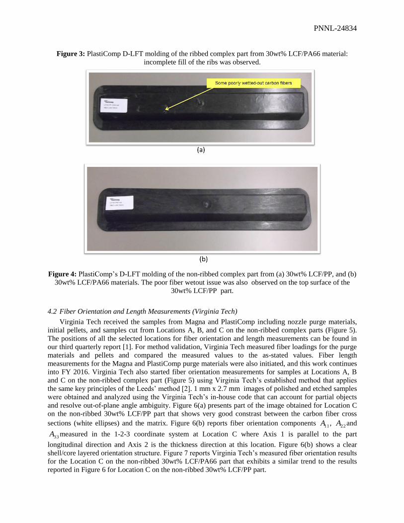
Figure 3: PlastiComp D-LFT molding of the ribbed complex part from 30wt% LCF/PA66 material:
incomplete fill of the ribs was observed.
Figure 4: PlastiComp’s D-LFT molding of the non-ribbed complex part from (a) 30wt% LCF/PP, and (b)
30wt% LCF/PA66 materials. The poor fiber wetout issue was also observed on the top surface of the
30wt% LCF/PP part.
4.2 Fiber Orientation and Length Measurements (Virginia Tech)
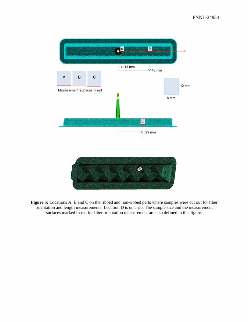
Virginia Tech received the samples from Magna and PlastiComp including nozzle purge materials,
initial pellets, and samples cut from Locations A, B, and C on the non-ribbed complex parts (Figure 5).
The positions of all the selected locations for fiber orientation and length measurements can be found in
our third quarterly report [1]. For method validation, Virginia Tech measured fiber loadings for the purge
materials and pellets and compared the measured values to the as-stated values. Fiber length
measurements for the Magna and PlastiComp purge materials were also initiated, and this work continues
into FY 2016. Virginia Tech also started fiber orientation measurements for samples at Locations A, B
and C on the non-ribbed complex part (Figure 5) using Virginia Tech’s established method that applies
the same key principles of the Leeds’ method [2]. 1 mm x 2.7 mm images of polished and etched samples
were obtained and analyzed using the Virginia Tech’s in-house code that can account for partial objects
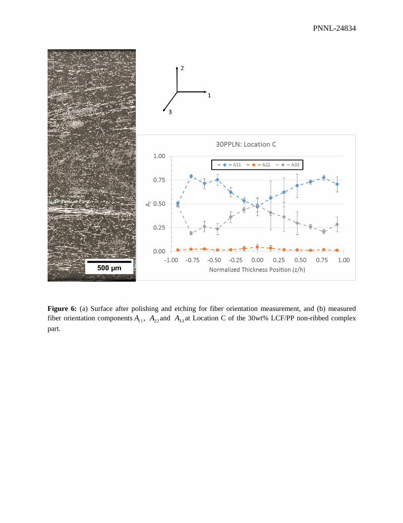
and resolve out-of-plane angle ambiguity. Figure 6(a) presents part of the image obtained for Location C
on the non-ribbed 30wt% LCF/PP part that shows very good constrast between the carbon fiber cross
sections (white ellipses) and the matrix. Figure 6(b) reports fiber orientation components 11A , 22A and
33A measured in the 1-2-3 coordinate system at Location C where Axis 1 is parallel to the part
longitudinal direction and Axis 2 is the thickness direction at this location. Figure 6(b) shows a clear
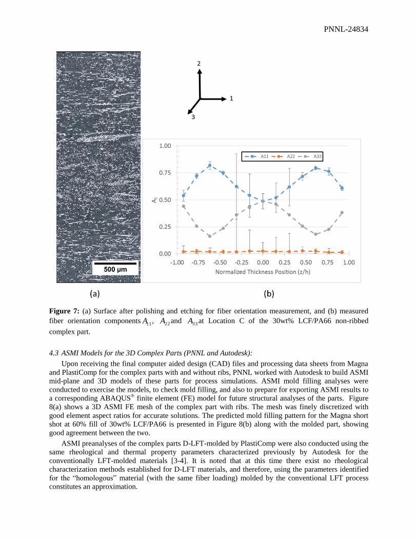
shell/core layered orientation structure. Figure 7 reports Virginia Tech’s measured fiber orientation results
for the Location C on the non-ribbed 30wt% LCF/PA66 part that exhibits a similar trend to the results
reported in Figure 6 for Location C on the non-ribbed 30wt% LCF/PP part.
PNNL-24834
Figure 5: Locations A, B and C on the ribbed and non-ribbed parts where samples were cut out for fiber
orientation and length measurements. Location D is on a rib. The sample size and the measurement
surfaces marked in red for fiber orientation measurement are also defined in this figure.
PNNL-24834
Figure 6: (a) Surface after polishing and etching for fiber orientation measurement, and (b) measured
fiber orientation components11A ,
22A and 33A at Location C of the 30wt% LCF/PP non-ribbed complex
part.
PNNL-24834
Figure 7: (a) Surface after polishing and etching for fiber orientation measurement, and (b) measured
fiber orientation components11A ,
22A and 33A at Location C of the 30wt% LCF/PA66 non-ribbed
complex part.
4.3 ASMI Models for the 3D Complex Parts (PNNL and Autodesk):
Upon receiving the final computer aided design (CAD) files and processing data sheets from Magna
and PlastiComp for the complex parts with and without ribs, PNNL worked with Autodesk to build ASMI
mid-plane and 3D models of these parts for process simulations. ASMI mold filling analyses were
conducted to exercise the models, to check mold filling, and also to prepare for exporting ASMI results to
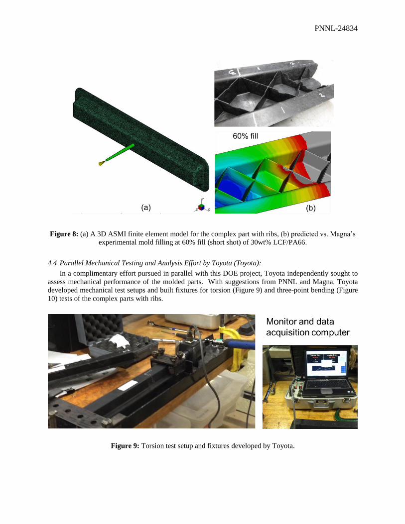
a corresponding ABAQUS® finite element (FE) model for future structural analyses of the parts. Figure
8(a) shows a 3D ASMI FE mesh of the complex part with ribs. The mesh was finely discretized with
good element aspect ratios for accurate solutions. The predicted mold filling pattern for the Magna short
shot at 60% fill of 30wt% LCF/PA66 is presented in Figure 8(b) along with the molded part, showing
good agreement between the two.
ASMI preanalyses of the complex parts D-LFT-molded by PlastiComp were also conducted using the
same rheological and thermal property parameters characterized previously by Autodesk for the
conventionally LFT-molded materials [3-4]. It is noted that at this time there exist no rheological
characterization methods established for D-LFT materials, and therefore, using the parameters identified
for the “homologous” material (with the same fiber loading) molded by the conventional LFT process
constitutes an approximation.
PNNL-24834
Figure 8: (a) A 3D ASMI finite element model for the complex part with ribs, (b) predicted vs. Magna’s
experimental mold filling at 60% fill (short shot) of 30wt% LCF/PA66.
4.4 Parallel Mechanical Testing and Analysis Effort by Toyota (Toyota):
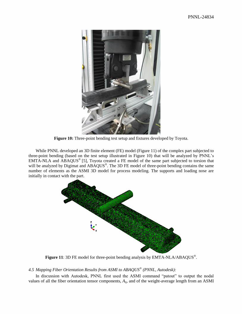
In a complimentary effort pursued in parallel with this DOE project, Toyota independently sought to
assess mechanical performance of the molded parts. With suggestions from PNNL and Magna, Toyota
developed mechanical test setups and built fixtures for torsion (Figure 9) and three-point bending (Figure
10) tests of the complex parts with ribs.
Figure 9: Torsion test setup and fixtures developed by Toyota.
PNNL-24834
Figure 10: Three-point bending test setup and fixtures developed by Toyota.
While PNNL developed an 3D finite element (FE) model (Figure 11) of the complex part subjected to
three-point bending (based on the test setup illustrated in Figure 10) that will be analyzed by PNNL’s
EMTA-NLA and ABAQUS®
[5], Toyota created a FE model of the same part subjected to torsion that
will be analyzed by Digimat and ABAQUS®. The 3D FE model of three-point bending contains the same
number of elements as the ASMI 3D model for process modeling. The supports and loading nose are
initially in contact with the part.
Figure 11: 3D FE model for three-point bending analysis by EMTA-NLA/ABAQUS®.
4.5 Mapping Fiber Orientation Results from ASMI to ABAQUS® (PNNL, Autodesk):
In discussion with Autodesk, PNNL first used the ASMI command “patout” to output the nodal
values of all the fiber orientation tensor components, Aij, and of the weight-average length from an ASMI
PNNL-24834
analysis. Next, the use of the ASMI command “MPI2ABQ” has allowed creating an ABAQUS® input file
that contains exactly the same 3D finite element mesh information as the ASMI 3D mesh (e.g., same node
coordinates and element connectivity). PNNL then developed a procedure in PNNL’s EMTA-NLA to
import ASMI’s nodal fiber orientation and length results into the as-created ABAQUS® mesh. Finally, to
complete the FE model for the complex part subjected to three-point bending (Figure 11), it was
necessary to include the model for the supports and loading nose, application of boundary conditions, the
model for the contact of the part with the supports and loading nose as well as the material assignment for
all these entities. In this work, the elastic behavior model of EMTA-NLA will be used in ABAQUS®
analyses to design the part in the final stage considering weight and cost saving requirements.
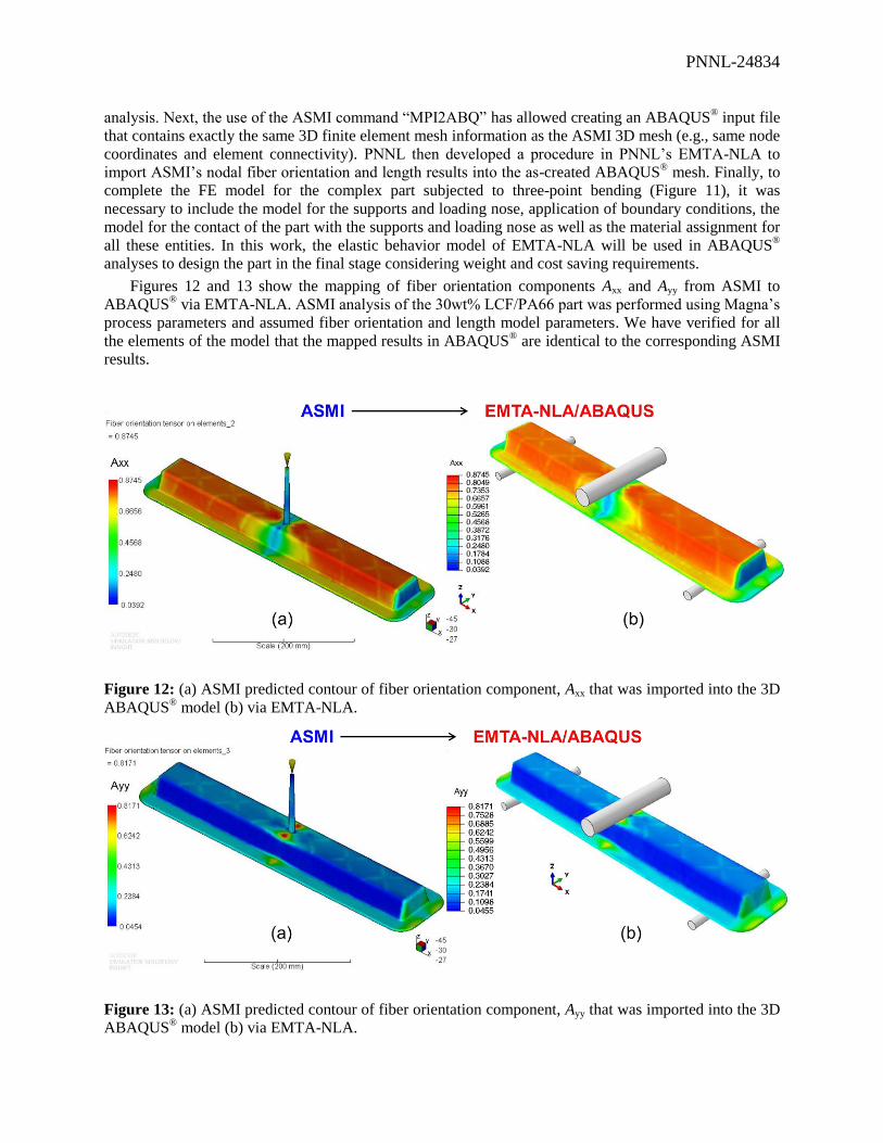
Figures 12 and 13 show the mapping of fiber orientation components Axx and Ayy from ASMI to
ABAQUS® via EMTA-NLA. ASMI analysis of the 30wt% LCF/PA66 part was performed using Magna’s
process parameters and assumed fiber orientation and length model parameters. We have verified for all
the elements of the model that the mapped results in ABAQUS® are identical to the corresponding ASMI
results.
Figure 12: (a) ASMI predicted contour of fiber orientation component, Axx that was imported into the 3D
ABAQUS® model (b) via EMTA-NLA.
Figure 13: (a) ASMI predicted contour of fiber orientation component, Ayy that was imported into the 3D
ABAQUS® model (b) via EMTA-NLA.

PNNL-24834
5 Publications/Presentations
None
4 Patents
None
5 Future Plans
Magna will cut out samples from the designated locations of the ribbed parts molded by Magna as
well as the ribbed and non-ribbed parts molded by PlastiComp and ship the samples to Virginia Tech for
fiber length and fiber orientation measurements. Virginia Tech continues performing fiber orientation and
length measurements for all the samples cut out from the Magna and PlastiComp parts. PNNL will work
with Autodesk to validate fiber orientation and length predictions upon receiving measured data from
Virginia Tech. In addition, Toyota will pursue structural analyses of the ribbed parts subjected to torsion
while PNNL will pursue analyses of the same parts subjected to three-point bending. Structural responses
will be considered once the ASMI fiber orientation and length predictions are validated for the complex
parts.
6 References
[1] Nguyen, B.N.; Fifield, L.S.; Mori, S.; Gandhi, U.N.; Wang, J.; Franco, C.; Wollan, E.J.; Tucker III,
C.L. (2015 c). Predictive Engineering Tools for Injection-Molded Long-Carbon-Fiber Thermoplastic
Composites – FY 2015 Third Quarterly Report; PNNL-24472; Pacific Northwest National Laboratory,
Richland, WA.
[2] Hine PJ, Davidson N, Duckett RA, Clarke AR, and Ward IM. Hydrostatically Extruded Glass-Fiber-
Reinforced Polyoxymethylene. I: the Development of Fiber and Matrix Orientation, Polymer Composites,
1996, 17:720-9.
[3] Autodesk, Inc. (2014 a). “Material Testing Report: MAT5404.”
[4] Autodesk, Inc. (2014 c). “Material Testing Report: MAT5406.”
[5] Nguyen, B.N.; Kunc, V.; Jin, X.; Tucker III, C.L.; Costa, F. Injection-Molded Long-Fiber
Thermoplastic Composites: From Process Modeling to Prediction of Mechanical Properties. In
Proceedings of the 28th Technical Conference of ASC; Paper # 13, Bakis, C.E., Ed., DEStech
Publications, Inc., Lancaster, PA, 2013.
7 Budgetary Information