Influence of ground motion duration on structural dynamic ...
PREDICTION OF STRUCTURAL SUPPORTS INFLUENCE ON ROTATING MACHINERY DYNAMICS
Dr. Leonid Moroz SoftInWay Inc.
1500 District Ave, Burlington, MA 01803, USA [email protected]
Dr. Leonid Romanenko SoftInWay Inc.
1500 District Ave, Burlington, MA 01803, USA [email protected]
Dr. Roman Kochurov SoftInWay Inc.
1500 District Ave, Burlington, MA 01803, USA [email protected]
Evgen Kashtanov SoftInWay Inc.
1500 District Ave, Burlington, MA 01803, USA [email protected]
ABSTRACT Rotor lifetime and safety primarily depend on the level of
rotor vibration. In order to avoid unwanted consequences for the plant due to rotor damage and to meet the highest requirements of design reliability, accurate rotor dynamic predictions are mandatory. Having the correct rotor model is a critical issue in dynamics prediction. Often research activities are focused only on the rotor-bearing system analysis. However, generally, the whole system, which includes the rotor, bearings, casing and structural supports should be considered. Special attention should be paid to the influence of structural supports which reveals when the rotor is supported by ball bearings because of low damping and high bearing stiffness.
The approach presented in this paper allows us to simulate the influence of structural supports on rotor dynamics response and as a result, the full picture of rotor-bearing-support system resonances can be analyzed to avoid potential problems. The methodology is based on support vibrations modal reduction technics. According to the approach, the natural frequencies and their mode shapes should be calculated for the separate support structure applying a three-dimensional finite element model and the relative displacements at bearing location points are measured. Supports’ normalized modal characteristics (modal mass and modal stiffness) for each vibration mode should then be imported in a rotor dynamics algorithm for rotor unbalance response analysis.
The approach allows for simulation of different types of support structures such as bearing pedestals, steel foundations, tabletop-type foundation, frame and pipe supports of arbitrary geometry, and so on. Validation based on the Jeffcott rotor model is presented. The current methodology has been applied to a
single- stage compressor’s rotor-bearing-support system which was manufactured and commissioned. The results of the simulations are discussed.
NOMENCLATURE RBFS – rotor-bearing structural supports system RBS – rotor-bearing system FE – finite element FEA – finite element analysis DF – dynamic forces DOF – degree of freedom MP – modal parameters
INTRODUCTION Prediction of rotor vibrations is a significant task in rotating
machinery design and analysis. Many scientists are involved in rotor dynamics research, and the rotor dynamics analysis theory is presented in various fundamental books [1], [2], [3].
A good practice for safe rotor design typically involves the avoidance of any resonance situation at operating speeds with some margins including resonances by a reason of structural supports vibration. If the design can’t be changed to satisfy frequency margins, the vibration amplitudes and forces acting on the bearings have to be measured and analyzed according to standards or company design practice [4].
It is well-known that critical speeds of rotor-bearing systems which are supported by pedestal or steel foundation are different in comparison to separate rotor-bearing systems without supports [5]. New resonance peaks in the rotor amplitude-frequency response characteristics also appear due to multi-mode vibrations of the support structure. In most cases, ordinary
Proceedings of ASME Turbo Expo 2017: Turbomachinery Technical Conference and Exposition GT2017
June 26-30, 2017, Charlotte, NC, USA
GT2017-63035
1 Copyright © 2017 ASME
rough methods which are based on the supports stiffness, damping, and mass input can’t give a full picture of rotor-bearing-supports system vibrations. Some true resonance conditions produced by these supports might be out of proper attention. The difference between the values of critical speeds calculated for RBS against RBFS can be significant and can be reached from 10 to 30 percent [3].
To account for the structural support effect on rotor dynamics, several approaches can be used. A classical approach for rotor dynamics simulation is to model the support structure of a rotor-bearing system with a series of the journal bearing stiffness and damping and a spring-damper-mass system which represents support structure/casing mass, stiffness, and damping. In most cases, it is very difficult to estimate the mass, stiffness and damping characteristics of the rotor support.
One way to leverage these uncertainties is to perform equipment vibration measurements. Methods based on a dynamic model of the support structure creation from measured frequency responses is applied and discussed in [5], [7], and [8]. However, in many cases, especially at the rotor system design phase, experimental results are not available or it’s undesirable from a cost-effectiveness point of view.
Another approach is to simulate a full conjugated model which includes detailed 3D FEA supports and rotor-bearing system models. The disadvantages of such an approach are that it results in an extremely complicated modeling process of the full system and long calculation time [9], [10].
An approach to reduce calculation time and overall complexity of FE models, based on modeling the rotor with solid elements and utilized transfer functions to represent the flexible support is proposed in [11]. A transfer function method is used to evaluate coupled rotor-foundation eigenfrequencies and to identify critical resonances in [12] and the comparison with measured data is discussed. A case study of a real shaft train is run based on MDOF approach including validation with experimental results [13]. In [14] the research is performed to study how turbomachines baseplates cause coupling transfer functions between bearings. Experimental validation of the developed approach is performed for the multistage centrifugal compressor.
The main goal of this article is to present a practical approach which allows one to account for structural support influence in terms of rotor dynamics response with high accuracy and effectiveness in relation to engineering efforts. This methodology was implemented in a rotor dynamics analysis software and is based on support vibrations modal reduction technics. As a preliminary step, the natural frequencies and their modal shapes are calculated for the separate support structure applying a three-dimensional FE model. Calculated relative displacements at the bearing location points and support’s normalized modal characteristics (modal mass and modal stiffness) for each vibration mode is then imported in rotor dynamics beam-type FE model. The advantages of the current approach are the automation between all simulation steps, low calculation time and high accuracy of results which is confirmed by test examples.
1. METHODOLOGY DESCRIPTION The equation of rotor-bearing system motion can be written
in the following form:
𝑀𝑀�̈�𝑥 + 𝐵𝐵�̇�𝑥 + 𝐾𝐾𝑥𝑥 = 𝐹𝐹(𝑡𝑡) + 𝑅𝑅(𝑡𝑡), (1) 𝐵𝐵 = 𝐺𝐺 + 𝐷𝐷, (2)
where 𝑥𝑥– rotor displacement vector, �̇�𝑥–rotor velocity vector, �̈�𝑥–rotor acceleration vector, 𝑀𝑀–mass matrix, 𝐺𝐺 – gyroscopic matrix, 𝐷𝐷 – damping matrix, 𝐾𝐾 – stiffness matrix, 𝐹𝐹(𝑡𝑡) –excitation forces vector, 𝑅𝑅(𝑡𝑡) – bearing reactions vector for the rotor.
The equation of structural supports motion can be written as follows:
𝑀𝑀1�̈�𝑦 + 𝐷𝐷1�̇�𝑦 + 𝐾𝐾1𝑦𝑦 = 𝑅𝑅1(𝑡𝑡), (3) where 𝑦𝑦, �̇�𝑦, �̈�𝑦 – support structure displacement, velocity and acceleration; 𝑀𝑀1, 𝐷𝐷1, 𝐾𝐾1 − mass, damping and stiffness matrixes correspondingly; 𝑅𝑅1(𝑡𝑡) − bearings reactions vector for supports.
Bearings reactions vector 𝑅𝑅(𝑡𝑡) = − 𝑅𝑅1(𝑡𝑡) can be expressed in terms of rotor and support structure displacement and velocity at bearings location as follows:
𝑅𝑅(𝑡𝑡) = 𝐾𝐾𝐵𝐵(𝑥𝑥𝐵𝐵 − 𝑦𝑦𝐵𝐵) + 𝐷𝐷𝐵𝐵(�̇�𝑥𝐵𝐵 − �̇�𝑦𝐵𝐵), (4) where 𝐾𝐾𝐵𝐵 equals bearing stiffness matrix, 𝐷𝐷𝐵𝐵 is the bearing damping matrix, 𝑥𝑥𝐵𝐵 , �̇�𝑥𝐵𝐵 is equal to rotor displacement and velocity at bearings location, and 𝑦𝑦𝐵𝐵 , �̇�𝑦𝐵𝐵 represents structural supports displacement and velocity at bearings location.
Structural support displacements can be expanded as follows:
𝑦𝑦(𝑡𝑡) = 𝑦𝑦�𝛼𝛼(𝑡𝑡), (5) where 𝑦𝑦� is the matrix of foundation’s eigenvectors, normalized by matrix of mass (or M-normal method), 𝛼𝛼(𝑡𝑡) is the modal coefficients. Generally, the natural modes can be M-normalized (to the mass matrix), or K-normalized (to the stiffness matrix) – these two methods of normalization gives identical results.
The modal coefficients 𝛼𝛼(𝑡𝑡) are satisfy following equations
�̈�𝛼 + 𝛿𝛿�̇�𝛼 + 𝑝𝑝2𝛼𝛼 = 𝑅𝑅1(𝑡𝑡)𝑦𝑦�, (6) where 𝛿𝛿 is the unitary matrix of modal damping and 𝑝𝑝2 is the unitary matrix of squared natural frequencies. At this step we assume that modal shapes are not coupled by resistance forces.
The major concern in rotor dynamics prediction – rotor forced vibrations which are the results of unbalance inertia forces (unbalance response). These forces can be presented in the following form:
𝐹𝐹(𝑡𝑡) = 𝐴𝐴𝐴𝐴𝐴𝐴𝐴𝐴(𝜔𝜔𝑡𝑡) + 𝐵𝐵𝐴𝐴𝐵𝐵𝐵𝐵(𝜔𝜔𝑡𝑡), (7)
2 Copyright © 2017 ASME

where 𝐴𝐴, 𝐵𝐵 are the coefficients’ vectors and 𝜔𝜔 is the angular rotor velocity.
Nodal displacement from equation (1) and modal coefficients from equation (5) can be found in the following form:
𝑥𝑥(𝑡𝑡) = 𝐶𝐶1𝐴𝐴𝐴𝐴𝐴𝐴(𝜔𝜔𝑡𝑡) + 𝐶𝐶2 sin(𝜔𝜔𝑡𝑡); (8) 𝛼𝛼(𝑡𝑡) = 𝐶𝐶3𝐴𝐴𝐴𝐴𝐴𝐴(𝜔𝜔𝑡𝑡) + 𝐶𝐶4 sin(𝜔𝜔𝑡𝑡), (9)
where coefficients 𝐶𝐶1,𝐶𝐶2,𝐶𝐶3,𝐶𝐶4 is determined from the system of linear algebraic equations.
Stability analysis is performed supposing the excitation forces are equal to zero and solution is written in the following form:
𝑥𝑥(𝑡𝑡) = 𝑅𝑅𝑅𝑅�𝐶𝐶5𝑅𝑅𝑥𝑥𝑝𝑝(𝜆𝜆𝑡𝑡)�; (10) 𝛼𝛼(𝑡𝑡) = 𝑅𝑅𝑅𝑅�𝐶𝐶6𝑅𝑅𝑥𝑥𝑝𝑝(𝜆𝜆𝑡𝑡)�, (11)
where 𝐶𝐶5, 𝐶𝐶6 are eigenvectors and 𝜆𝜆 – eigenvalues. Analyzing the real part sign, we made a conclusion on system stability. If all eigenvalues have a negative real part, the motion is stable. If just one real part is positive, the motion is unstable.
Thus to describe structural supports, (2 + 𝑁𝑁𝐵𝐵)𝑁𝑁𝑀𝑀 number of parameters, where 𝑁𝑁𝐵𝐵 represents the number of bearings and 𝑁𝑁𝑀𝑀 represents the number of supports’ natural frequencies, should be determined.
Most state-of-the-art rotor dynamics software do use beam elements to model the shaft. Such an approach gives accurate analysis results (especially beams according to the Timoshenko formulation) and significantly speed-up calculation time. The proposed method for structural supports effect simulation described above allows for use of the beams elements for rotor dynamics analysis while structural supports/foundation) simulation is performed with 3D FE approach.
2. JEFFCOTT ROTOR-BEARING-STRUCTURAL SUPPORTS SYSTEM SIMULATION. METHODOLOGY VALIDATION
The Jeffcott rotor model with structural supports presented on the sketch in Fig. 1 is used for methodology validation.
Figure 1: Jeffcott Rotor-Bearing Supports System
Isotropic bearings with stiffness’s of C1=10E6 N/m and C2=10E7 N/m are used in the analysis.
To validate the proposed methodology, two identical rotor models were created in the rotor dynamics module (Fig. 2) and FE software (Fig. 3). Timoshenko theory is used to developed mechanical models for the rotor.
Figure 2: FE Model for Rotor-Bearing System without Structural Supports
The simple support structure was modeled using 3D solid
20-node hexahedral elements – see Fig. 3.
Figure 3: FE Model for Rotor-Bearing System with Structural Supports
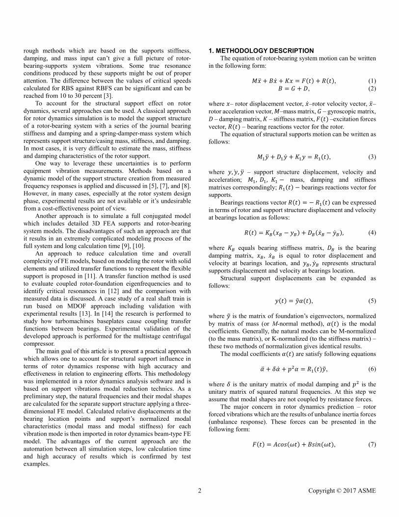
According to the proposed methodology, at the first step, the
separate supports structure was calculated and modal characteristics were used as the input data (Fig. 4) to simulate a rotor-bearing system response.
3 Copyright © 2017 ASME
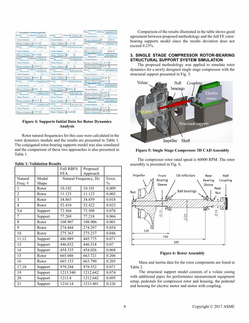
Figure 4: Supports Initial Data for Rotor Dynamics Analysis
Rotor natural frequencies for this case were calculated in the
rotor dynamics module and the results are presented in Table 1. The conjugated rotor-bearing supports model was also simulated and the comparison of these two approaches is also presented in Table 1.
Table 1: Validation Results
Full RBFS FEA
Proposed Approach
Natural Freq. #
Modal Shape
Natural Frequency, Hz Error, %
1 Rotor 10.192 10.191 0.009 2 Rotor 11.123 11.123 0.002 3 Rotor 34.865 34.859 0.018 4 Rotor 52.410 52.422 0.023 5,6 Support 72.564 72.509 0.076 7 Support 77.269 77.218 0.066 8 Rotor 108.907 108.906 0.001 9 Rotor 274.444 274.297 0.054 10 Rotor 275.363 275.237 0.046 11,12 Support 446.089 445.775 0.071 13 Support 446.832 446.518 0.07 14 Support 454.335 454.026 0.068 15 Rotor 665.086 663.721 0.206 16 Rotor 665.153 663.790 0.205 17,18 Support 979.244 978.552 0.071 19 Support 1213.540 1212.642 0.074 20 Support 1213.8 1212.642 0.095 21 Support 1216.14 1213.401 0.226
Comparison of the results illustrated in the table shows good agreement between proposed methodology and the full FE rotor-bearing supports model since the results deviation does not exceed 0.23%.
3. SINGLE STAGE COMPRESSOR ROTOR-BEARING STRUCTURAL SUPPORT SYSTEM SIMULATION
The proposed methodology was applied to simulate rotor dynamics for a newly designed single stage compressor with the structural support presented in Fig. 5.
Figure 5: Single Stage Compressor 3D CAD Assembly
The compressor rotor rated speed is 60000 RPM. The rotor assembly is presented in Fig. 6.
Figure 6: Rotor Assembly
Mass and inertia data for the rotor components are listed in Table 2.
The structural support model consists of a volute casing with additional pipes for performance measurement equipment setup, pedestals for compressor rotor and housing, the pedestal and housing for electric motor and motor with coupling.
4 Copyright © 2017 ASME
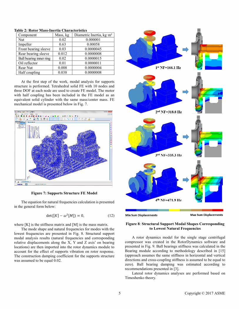
Table 2: Rotor Mass-Inertia Characteristics Component Mass, kg Diametric Inertia, kg·m² Nut 0.02 0.000001 Impeller 0.63 0.00058 Front bearing sleeve 0.03 0.0000045 Rear bearing sleeve 0.012 0.0000008 Ball bearing inner ring 0.02 0.0000015 Oil reflector 0.01 0.0000011 Rear Nut 0.008 0.0000004 Half coupling 0.038 0.0000008
At the first step of the work, modal analysis for supports
structure is performed. Tetrahedral solid FE with 10 nodes and three DOF at each node are used to create FE model. The motor with half coupling has been included in the FE model as an equivalent solid cylinder with the same mass/center mass. FE mechanical model is presented below in Fig. 7.
Figure 7: Supports Structure FE Model The equation for natural frequencies calculation is presented
in the general form below:
det ([𝐾𝐾] − 𝜔𝜔2[𝑀𝑀]) = 0, (12) where [K] is the stiffness matrix and [M] is the mass matrix.
The mode shape and natural frequencies for modes with the lowest frequencies are presented in Fig. 8. Structural support modal analysis results (natural frequencies and corresponding relative displacements along the X, Y and Z axis’ on bearing locations) are then imported into the rotor dynamics module to account for the effect of supports vibration on rotor response. The construction damping coefficient for the supports structure was assumed to be equal 0.02.
Figure 8: Structural Support Modal Shapes Corresponding
to Lowest Natural Frequencies
A rotor dynamics model for the single stage centrifugal compressor was created in the RotorDynamics software and presented in Fig. 9. Ball bearings stiffness was calculated in the Bearing module according to methodology described in [15] (approach assumes the same stiffness in horizontal and vertical directions and cross-coupling stiffness is assumed to be equal to zero). Ball bearing damping was estimated according to recommendations presented in [3].
Lateral rotor dynamics analyses are performed based on Timoshenko theory.
5 Copyright © 2017 ASME
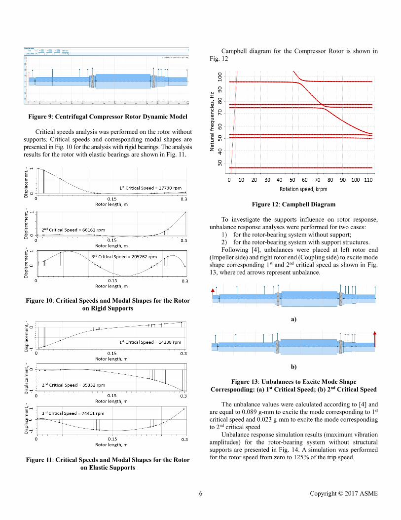
Figure 9: Centrifugal Compressor Rotor Dynamic Model
Critical speeds analysis was performed on the rotor without supports. Critical speeds and corresponding modal shapes are presented in Fig. 10 for the analysis with rigid bearings. The analysis results for the rotor with elastic bearings are shown in Fig. 11.
Figure 10: Critical Speeds and Modal Shapes for the Rotor
on Rigid Supports
Figure 11: Critical Speeds and Modal Shapes for the Rotor
on Elastic Supports
Campbell diagram for the Compressor Rotor is shown in Fig. 12
Figure 12: Campbell Diagram
To investigate the supports influence on rotor response, unbalance response analyses were performed for two cases:
1) for the rotor-bearing system without support; 2) for the rotor-bearing system with support structures. Following [4], unbalances were placed at left rotor end
(Impeller side) and right rotor end (Coupling side) to excite mode shape corresponding 1st and 2nd critical speed as shown in Fig. 13, where red arrows represent unbalance.
a)
b)
Figure 13: Unbalances to Excite Mode Shape Corresponding: (a) 1st Critical Speed; (b) 2nd Critical Speed
The unbalance values were calculated according to [4] and are equal to 0.089 g-mm to excite the mode corresponding to 1st critical speed and 0.023 g-mm to excite the mode corresponding to 2nd critical speed
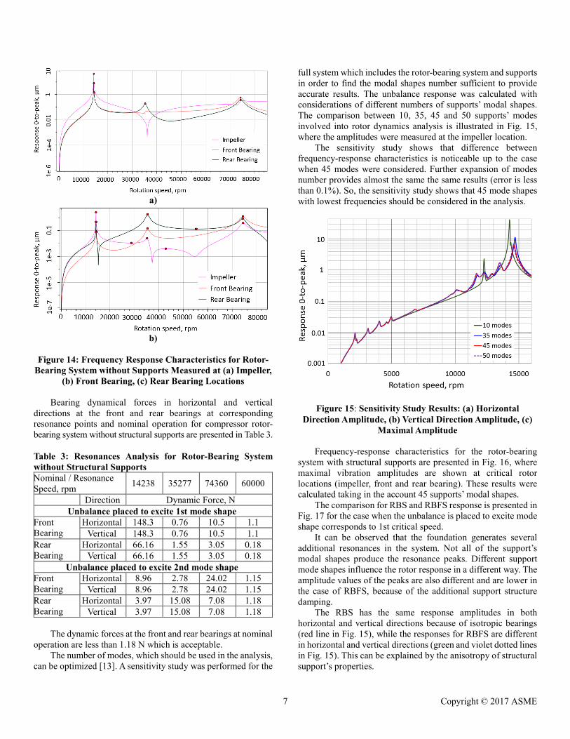
Unbalance response simulation results (maximum vibration amplitudes) for the rotor-bearing system without structural supports are presented in Fig. 14. A simulation was performed for the rotor speed from zero to 125% of the trip speed.
6 Copyright © 2017 ASME
a)
b)
Figure 14: Frequency Response Characteristics for Rotor-
Bearing System without Supports Measured at (a) Impeller, (b) Front Bearing, (c) Rear Bearing Locations
Bearing dynamical forces in horizontal and vertical
directions at the front and rear bearings at corresponding resonance points and nominal operation for compressor rotor-bearing system without structural supports are presented in Table 3. Table 3: Resonances Analysis for Rotor-Bearing System without Structural Supports Nominal / Resonance Speed, rpm 14238 35277 74360 60000
Direction Dynamic Force, N Unbalance placed to excite 1st mode shape
Front Bearing
Horizontal 148.3 0.76 10.5 1.1 Vertical 148.3 0.76 10.5 1.1
Rear Bearing
Horizontal 66.16 1.55 3.05 0.18 Vertical 66.16 1.55 3.05 0.18
Unbalance placed to excite 2nd mode shape Front Bearing
Horizontal 8.96 2.78 24.02 1.15 Vertical 8.96 2.78 24.02 1.15
Rear Bearing
Horizontal 3.97 15.08 7.08 1.18 Vertical 3.97 15.08 7.08 1.18
The dynamic forces at the front and rear bearings at nominal
operation are less than 1.18 N which is acceptable. The number of modes, which should be used in the analysis,
can be optimized [13]. A sensitivity study was performed for the
full system which includes the rotor-bearing system and supports in order to find the modal shapes number sufficient to provide accurate results. The unbalance response was calculated with considerations of different numbers of supports’ modal shapes. The comparison between 10, 35, 45 and 50 supports’ modes involved into rotor dynamics analysis is illustrated in Fig. 15, where the amplitudes were measured at the impeller location.
The sensitivity study shows that difference between frequency-response characteristics is noticeable up to the case when 45 modes were considered. Further expansion of modes number provides almost the same the same results (error is less than 0.1%). So, the sensitivity study shows that 45 mode shapes with lowest frequencies should be considered in the analysis.
Figure 15: Sensitivity Study Results: (a) Horizontal Direction Amplitude, (b) Vertical Direction Amplitude, (c)
Maximal Amplitude
Frequency-response characteristics for the rotor-bearing system with structural supports are presented in Fig. 16, where maximal vibration amplitudes are shown at critical rotor locations (impeller, front and rear bearing). These results were calculated taking in the account 45 supports’ modal shapes.
The comparison for RBS and RBFS response is presented in Fig. 17 for the case when the unbalance is placed to excite mode shape corresponds to 1st critical speed.
It can be observed that the foundation generates several additional resonances in the system. Not all of the support’s modal shapes produce the resonance peaks. Different support mode shapes influence the rotor response in a different way. The amplitude values of the peaks are also different and are lower in the case of RBFS, because of the additional support structure damping.
The RBS has the same response amplitudes in both horizontal and vertical directions because of isotropic bearings (red line in Fig. 15), while the responses for RBFS are different in horizontal and vertical directions (green and violet dotted lines in Fig. 15). This can be explained by the anisotropy of structural support’s properties.
7 Copyright © 2017 ASME

a)
b)
Figure 16: Frequency-response characteristics for RBFS. Unbalance applied to excite the mode corresponding to
(a) 1st critical speed (b) 2nd critical speed
Figure 17: The Comparison for RBS and RBFS Response
Bearing dynamical forces for compressor rotor-bearing system with structural supports are presented in Table 4. Table 4: Resonances Analysis for Rotor-Bearing System with Structural Supports Nominal / Resonance Speed, rpm 14571 35246 74600 60000
Direction Dynamic Force, N Unbalance placed to excite 1st mode shape
Front Bearing
Horizontal 25.10 0.67 10.28 0.17 Vertical 19.44 0.75 8.95 0.18
Rear Bearing
Horizontal 5.52 0.43 3.04 0.17 Vertical 8.92 1.53 2.62 0.18
Unbalance placed to excite 2nd mode shape Front Bearing
Horizontal 0.83 0.23 23.20 0.99 Vertical 0.79 2.59 20.70 1.15
Rear Bearing
Horizontal 0.33 2.24 7.19 1.16 Vertical 0.34 14.80 6.00 1.17
The dynamic forces at the front and rear bearings at nominal
operation are less than 1.17 N. The bearing DF for RBFS are decreased at resonance conditions in comparison to the RBS.
CONCLUSION Structural supports influence rotor response and should be
considered in the rotor dynamics analysis process at the design step. An improved automated approach for the structural support’s influence predictions on rotor dynamics is proposed. The main advantage of the methodology is automation and integration between all analysis steps within the software modules. Such approach accelerates a rotor-bearing-support system dynamics analysis:
- calculation time decreases in 5-7 times in comparison with full 3D models analysis;
- the modeling process is easier which also saves time. The validation of the methodology is done based on the
Jeffcott rotor model on simple solid structural supports and shows high accuracy in the results (the error is less than 0.3 percent).
The method was applied to single stage compressor lateral rotor dynamics, and influence of structural supports on rotor response have been studied including:
- supports mode shape number; - effect of supports stiffness anisotropy in vertical and
horizontal directions; - supports influence on bearings dynamical forces. The single stage compressor, described in the paper, is in the
final phase of commissioning and in the future, it’s planned to be tested to prove analysis methodology by experimental validation.
The method is recommended to be applied to many industrial applications (turbine, compressors, fans, pumps, and etc.), where rotating equipment is supported by pedestals, tabletop-type foundation, frame and pipe supports of arbitrary geometry supports.
8 Copyright © 2017 ASME

REFERENCES [1] Childs, D., 1993, Turbomachinery rotordynamics
phenomena, modeling, and analysis, Wiley-Interscience, New Jersey, USA.
[2] Rao, J.S., 1996, Rotor Dynamics, New Age, New Delhi, India.
[3] Kramer, E., 1993, Dynamics of rotors and foundations, Springer-Verlag, Berlin, Germany.
[4] API, 684, 2005. API recommended practice, American petroleum institute, Washington, USA.
[5] Neto, R.R., Bogh, D.S., and Flammia, M., 2008, ”Some Experiences on Rigid and Flexible Rotors in Induction Motors Driving Critical Equipment in Petroleum and Chemical Plants”, IEEE Transactions on Industry Applications.
[6] Florian, C., Hiss, G., and Zimmer, A. K., 2004, “Methods for generating rotor dynamic models in retrofits of large steam turbines from onsite measurements”, ASME Turbo Expo, Düsseldorf, Germany, GT2014-26217.
[7] Subbiach, R., 2012, “On the determination of bearing support pedestal conditions using shaker testing”, 10th internal conference on vibrations in rotatory machining, London, Great Britain.
[8] Yu, M., Feng, N., and Hahn, E., 2012, “Identification of foundations in rotating machinery using modal parameters”, 10th internal conference on vibrations in rotatory machining, London, Great Britain.
[9] Yan, W., Shaposhnikov, K.,Yu, P., Ma, Y., and Hong, J., 2015, “Experimental investigation and numerical analysis on influence of foundation excitation on the dynamics of the rotor system”, ASME Turbo Expo, Montreal, Canada.
[10] Ming, F., Tao, W., and Hui, L., 2012, ”Dynamics of turbine foundation considering full interaction among facility, structure and soil”, 15 WCEE , Lisbon, Portugal.
[11] Lingnan, Hu, and Palazzolo, A., 2016, “Solid element rotordynamic modeling of a rotor on a flexible support structure utilizing mimo support transfer functions” ASME Turbo Expo, Seoul, South Korea.
[12] Ehehalt, U., Luneburg, B., Daniel, C., Strackeljan, J., and Woschke, E., 2009, “Methods to Incorporate Foundation Elasticities in Rotordynamic Calculations”, 8th International Conference on Vibrations in Rotating machines, Vienna, Austria.
[13] Kruger, T. D., Liberatore, S., Knopf, E., and Clark, A., 2013, “Consideration of complex support structure dynamics in rotordynamic assessments”, ASME Turbo Expo, San Antonio, Texas, USA. GT2013-95196.
[14] Meli, E., Pallini, G., Rindi, A., Capanni, F., Rossin, S., and Panara, D., 2015, “Effect of support structure dynamics on centrifugal compressor rotor response”, III Middle East Turbomachinery Symposium, Doha, Qatar.
[15] Gargiulo Jr., E.P., 1980, “A Simple Way to Estimate Bearing Stiffness”, Machine Design. 5, pp. 107-110.
9 Copyright © 2017 ASME