Precont KS · 8 ACS-CONTROL-SYSTEM GmbH l Lauterbachstr. 57 l D-84307 Eggenfelden l l...
12
01.14 Technical manual Main features 2-wire 4...20mA or 3-wire 0...10V technology Pressure switch with pnp switching output from 5 up to 95% adjustable Hysteresis from 1,5% up to 20% adjustable Polysilicone resp. thin film sensor with metallic membrane Pressure ranges fine leveled acc. to DIN 16 128 Overload limit up to 4-times of the measurement range Version with damping system Housing in high-grade steel in protection class IP 65 Precont KS Transmitter With metallic membrane from 0...400 bar, Precision 0,15%, 2-wire 4...20mA or 3-wire 0...10V technology
-
Upload
truongkhuong -
Category
Documents
-
view
217 -
download
0
Transcript of Precont KS · 8 ACS-CONTROL-SYSTEM GmbH l Lauterbachstr. 57 l D-84307 Eggenfelden l l...

01.14Technical manual
Main features
2-wire 4...20mA or 3-wire 0...10V technology
Pressure switch with pnp switching output from 5 up to 95% adjustable
Hysteresis from 1,5% up to 20% adjustable
Polysilicone resp. thin film sensor with metallic membrane
Pressure ranges fine leveled acc. to DIN 16 128
Overload limit up to 4-times of the measurement range
Version with damping system
Housing in high-grade steel in protection class IP 65
Precont KS
TransmitterWith metallic membrane from 0...400 bar,Precision 0,15%, 2-wire 4...20mA or3-wire 0...10V technology

ACS-CONTROL-SYSTEM GmbH l Lauterbachstr. 57 l D-84307 Eggenfelden l www.acs-controlsystem.de l [email protected]
You have purchased a high-grade and modern measuring device of ACS-CONTROL-SYSTEM GmbH.
We want to give thanks for your purchase and for your confidence to us.
The actual technical manual includes instructions for installation, electrical connection and inauguration, as well as the technical data of the device.
Modifications, that answer the purpose of the technical progress, are reserved byACS-CONTROL-SYSTEM GmbH without prior notice.
If a question occurs, that can‘t be answered by the listed informations, please call on our technicians team in Eggenfelden Tel: +49 8721/ 9668-0 or [email protected]
All rights reserved

ACS-CONTROL-SYSTEM GmbH l Lauterbachstr. 57 l D-84307 Eggenfelden l www.acs-controlsystem.de l [email protected] 3
IndexInstrument Safety . . . . . . . . . . . . . . . . . . . . . . . . . . . . . . . . . . . . . . . . . . . . . . . . . 4Unpacking the instrument . . . . . . . . . . . . . . . . . . . . . . . . . . . . . . . . . . . . . . . . . . . 4Installation . . . . . . . . . . . . . . . . . . . . . . . . . . . . . . . . . . . . . . . . . . . . . . . . . . . . . . . 4Electrical Connections . . . . . . . . . . . . . . . . . . . . . . . . . . . . . . . . . . . . . . . . . . . . . . 5Connecting diagram . . . . . . . . . . . . . . . . . . . . . . . . . . . . . . . . . . . . . . . . . . . . . . . . 6Operation . . . . . . . . . . . . . . . . . . . . . . . . . . . . . . . . . . . . . . . . . . . . . . . . . . . . . . . . 8 Checking the span 8 Checking the supply voltage 8 Checking span start and span end 8Maintance and trouble-shooting . . . . . . . . . . . . . . . . . . . . . . . . . . . . . . . . . . . . . . 8Shut-down . . . . . . . . . . . . . . . . . . . . . . . . . . . . . . . . . . . . . . . . . . . . . . . . . . . . . . . 8Dimension Drawings . . . . . . . . . . . . . . . . . . . . . . . . . . . . . . . . . . . . . . . . . . . . . . . 9Order code . . . . . . . . . . . . . . . . . . . . . . . . . . . . . . . . . . . . . . . . . . . . . . . . . . . . . . . 10

ACS-CONTROL-SYSTEM GmbH l Lauterbachstr. 57 l D-84307 Eggenfelden l www.acs-controlsystem.de l [email protected]
Instrument SafetyThis instrument was built and tested according to DIN 57 411 part 1 / VDE 0411part 1. Protective measures for electrical apparatus and was shipped in technicallysafe condition.Protection class II is applicable.In Order to maintain this condition and to ensure safe operation, the user must follow the hints and warnings given in these operating instructions.The instrument must be operated only by trained persons. Maintenance and repair should be carried out only by trained, qualified personnel familiar with the relevant hazards.The instrument may be operated within the specified environmental conditions (see data sheet) without impairing its safety.
Unpacking the instrumentRemove instrument and accessories from the packing. Enclosed standard accessories:Operating instructions 56001400Check, if the shipment is correct and complete and if the instrument was damaged by improper handling during transport and storage.
Warning!If the instrument is so heavily damaged that safe operation seems impossible, the instrument must not be taken into operation. We recommend to keep the original packing for shipment in case of maintenance or repair.
InstallationWhen selecting the place of installation, or before installing the transmitter, the rules given below must be followed:
- The freezing point of process media and condensates must be taken into account.- The specified temperature limits (see data sheet) under consideration of the heat radiation of
adjacent equipment must not be exeeded.- The pressure membrane must not be damaged, therefore, the plastics protective cap of the
threaded coupling of the transmitter should be removed only shortly before installation.- Before mounting, a sealing ring B to DIN 16258 must be fitted in front of the threaded coupling!
The sealing ring material depends on the process medium and must be selected by the user.- Mounting may be done using a 27 mm spanner.

ACS-CONTROL-SYSTEM GmbH l Lauterbachstr. 57 l D-84307 Eggenfelden l www.acs-controlsystem.de l [email protected] 5
Electrical ConnectionsAll eletrical wiring must conform to local standards (e.g. VDE 0100). The input and signal leads must be kept separate from mains and control leads.
The connections must be made according to the connecting diagram.
The transmitter may be energized only from power supply units with safe galvanic isolation from the mains (➔ VDE 0550).
The supply voltage must be direct current.
In order to prevent stray interference, we recommend using twisted and screened input leads. The screen must be connected to the terminal for grounded measurement. This terminal is connected conductantly with the metal housing of the transmitter.
When using an instrument socket according to DIN 43 650, the cable direction is selectable by removing the socket insert and re-fitting it at an angle of 90°.
NoteThe terminal for grounded measurement on the instrument connection is marked with symbol(protective earth).

ACS-CONTROL-SYSTEM GmbH l Lauterbachstr. 57 l D-84307 Eggenfelden l www.acs-controlsystem.de l [email protected]
Connecting diagram
Instrument socket DIN 43 650/CTwo-wire1 Output (+)2 Output (-)3 not connected
Measurement earthThree-wire1 Output (+)2 Supply and output (-)3 Supply (+)
Measurement earth
Cable endTwo-wire(red) output (+)(black) not connected(white) output (-)(blue) not connected(green) measurement earthThree-wire(red) output (+)(black) supply (+)(white) supply and output (-)(blue) not connected(green) measurement earth

ACS-CONTROL-SYSTEM GmbH l Lauterbachstr. 57 l D-84307 Eggenfelden l www.acs-controlsystem.de l [email protected] 7
Instrument socket DIN 43 650/ATwo-wire1 Output (+)2 Output (-)3 not connected
Measurement earthThree-wire1 Output (+)2 Supply and output (-)3 Supply (+)
Measurement earth
Round connector M12x1Two-wire1 (red) output (+)2 not connected3 (white) output (-)4 not connectedhousing - shieldThree-wire1 (red) output (+)2 (black) supply (+)3 (white) supply and output (-)4 not connectedhousing - shield

ACS-CONTROL-SYSTEM GmbH l Lauterbachstr. 57 l D-84307 Eggenfelden l www.acs-controlsystem.de l [email protected]
OperationWarning !If the instrument is damaged to an extent that safe operation seems impossible, take the instrument out of operation (➔section shut down) and protect it against accidental operation.
Checking the spanBefore commisioning, check if the span specified on the transmitter type label corresponds to the operating pressures at the measuring point. The maximum operating pressure must be lower than the span end value.
Checking the supply voltageTo avoid measurement errors, note that the supply voltage (DC) from the connected voltage source is sufficient.
The minimum voltage to at the transmitter terminals must be:
12 V DC across terminals 1+ and 2– (twowire conntection)
15 V DC across terminals 3+ and 2– (three-wire connection)
The maximum permissible DC voltage at the relevant terminals for two-wire and three-wire versions is 30 V DC.
Checking span start and span endThe instruments have a fixed range. The tolerance for span start and span end at an ambient temperature of 20 °C is ≤± 0,4% of the output signal span. When checking, the output value for span start and span end must be within this tolerance.
Maintance and trouble-shootingThe transmitter needs no maintance.
In case of trouble, the rest of the system (pressure lines, valves electrical wiring, connected units, etc.) should be checked.
Shut-downBefore permanent shut-down, disconnect the instrument from all voltage sources and protect it against accidental operation.
Before instrument switch-off, take care that other equipment and/or facilities is/ are not affected. If necessary, appropriate measures must be taken.
With final shut-down and scrapping of the instrument, appropriate disposal because of the silicone oil filling must be ensured.

ACS-CONTROL-SYSTEM GmbH l Lauterbachstr. 57 l D-84307 Eggenfelden l www.acs-controlsystem.de l [email protected] 9
Dimension Drawings
Electrical connection with Instrument socket DIN 43 650/C
Electrical connection with Instrument socket DIN 43 650/C** + 4 mm on versions with mechanical damping and device ≥ 40 bar.
Electrical connection with cable end
Electrical connection with cable end** + 4 mm on versions with mechanical damping and device ≥ 40 bar.
ACS-CONTROL-SYSTEM GmbH l Lauterbachstr. 57 l D-84307 Eggenfelden l www.acs-controlsystem.de l [email protected]
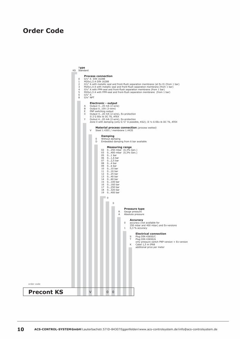
Precont KS V C 000
order code
TypeKS Standard
Process connection 0 G½” A DIN 16288 1 M20x1,5 A DIN 16288 2 G½” A with metallic seal and front-flush separation membrane (at Ex 0) (from 1 bar) 3 M20x1,5 A with metallic seal and front-flush separation membrane (from 1 bar) 4 G½” A with FPM-seal and front-flush separation membrane (from 1 bar) 5 M20x1,5 A with FPM-seal and front-flush separation membrane (from 1 bar) 6 G¼” A 8 G¼” NPT
Electronic - output A Output 4...20 mA (2-wire) B Output 0…10V (3-wire) E PNP switching output X Output 4...20 mA (2-wire), Ex-protection II 2 G EEx ib IIC T6, ATEX Y Outout 4...20 mA (2-wire), Ex-protection Zone 0 with damping (only G ½“ A possible, KS2); II ½ G EEx ib IIC T6, ATEX
Material process connection (process wetted) V Steel 1.4301 / membrane 1.4435
Damping 0 Without damping D Embedded damping from 6 bar available
Measuring range 02 0...250 mbar (0,3% Gen.) 03 0...400 mbar (0,3% Gen.) 05 0...1 bar 06 0...1,6 bar 07 0...2,5 bar 08 0...4 bar 09 0...6 bar 10 0...10 bar 11 0...16 bar 12 0...25 bar 13 0...40 bar 14 0...60 bar 15 0...100 bar 16 0...160 bar 17 0...250 bar 18 0...320 bar 19 0...400 bar
0
0
Pressure type R Gauge pressure A Absolute pressure
Accuracy 0 accuracy (not available for 250 mbar and 400 mbar) and Ex-versions 1 0,3 % accuracy
Electrical connection S Plug DIN 43650/C T Plug DIN 43650/A only pressure switch PNP-version + Ex-version K Cabel 1,5 m IP68 additional price per meter
Order Code

ACS-CONTROL-SYSTEM GmbH l Lauterbachstr. 57 l D-84307 Eggenfelden l www.acs-controlsystem.de l [email protected] 11