Precise Measurement of Heat of Combustion With a Bomb ... · standard procedures for measurements...
32
NBS MONOGRAPH 7 Precise Measurement of Heat of Combustion With a Bomb Calorimeter U.S. DEPARTMENT OF COMMERCE NATIONAL BUREAU OF STANDARDS
Transcript of Precise Measurement of Heat of Combustion With a Bomb ... · standard procedures for measurements...
NBS MONOGRAPH 7
Precise Measurement of Heat of Combustion With a Bomb Calorimeter
U.S. DEPARTMENT OF COMMERCENATIONAL BUREAU OF STANDARDS
T&E NATIONAL BUREAU OF STANDARDS
Functions and Activities
The functions of the National Bureau of Standards are set forth in the Act of Congress, March 3, 1901, as amended by Congress in Public Law 619, 1950* These include the development and maintenance of the national standards of measurement and the provision of means and methods for making measurements consistent with these standards; the determination of physical constants and properties of materials; the development of methods and instruments for testing materials, devices, and structures; advisory services to government agencies on scientific and technical problems; inven tion and development of devices to serve special needs of the Government; and the development of standard practices, codes, and specifications. The work includes basic and applied research, develop ment, engineering, instrumentation, testing, evaluation, calibration services, and various consultation and information services. Research projects are also performed for other government agencies when the work relates to and supplements the basic program of the Bureau or when the Bureau's unique competence is required. The scope of activities is suggested by the listing of divisions and sections cm the inside of the bade cover.
Publications
The results of the Bureau's work take the form of either actual equipment and devices or pub lished papers. These papers appear either in the Bureau's own series of publications or in the journals of professional and scientific societies. The Bureau itself publishes three periodicals available from die Government Printing Office: The Journal of Research, published in four separate sections, presents complete scientific and technical papers; the Technical News Bulletin presents summary and preliminary reports on work in progress; and Basic Radio Propagation Predictions provides data for determining the best frequencies to use for radio communications throughout the world. There are also five series of nonperiodical publications: Monographs, Applied Mathematics Series, Handbooks, Miscellaneous Publications, and Technical Notes.
Information on the Bureau's publications can be found in NBS Circular 460, Publications of the National Bureau of Standards ($1.25) and its Supplement ($1.50), available from the Super intendent of Documents, Government Printing Office, Washington 25, D.C.

UNITED STATES DEPARTMENT OF COMMERCE . Frederick H. Mueller, Secretary
NATIONAL BUREAU OF STANDARDS - A. V. Astin, Director
Precise Measurement of Heat of Combustion
With a Bomb Calorimeter
R. S. Jessup
National Bureau of Standards Monograph 7
Issued February 26, 1960
For sale by the Superintendent of Documents, U.S. Government Printing Office, Washington 25, D.C. - Price 25 cents

Contents-
1. Introduction. ___,__ 1.1. Definitions of
a. Heat units________________-_--_--. 1b. Heats of combustion^_-_______-_.__ 2
2. General discussion of bomb-calorimetric measure ments -______-________-___--______-_-.._--__ 2
3. Factors affecting accuracy in bomb-calorimetricmeasurements ___________________________ 3
3.1. Undesirable side reactions,_______________ 3a. Incomplete combustion.____________ 3b. Oxidation of crucible and fittings___ 4c. Reaction of acids with bomb material- 4d. Combustible impurities in oxygen.___ 4
3.2. Experimental techniques of individual meas urements________-_-___-_-_-___-__ 4
a. Weight of sample of combustible_____ 4b. Weight of calorimeter plus water_____ 5c. Temperature measurements _________ 6d. Firing energy_____________________- 9e. Materials in bomb__ _________-_-__ 9f. Acids formed in combustion _________ 9
4. Summarized directions for a bomb-calorimetric ex periment_______________________________ 10
4.1. Preliminary adjustment of apparatus.--.-. 104.2. Preparation and weighing of sample of
benzoic acid_--____----_--_-_-______ 104.3. Preparation of bomb___-__-_____________ 104.4. Weighing of calorimeter plus water______ 104.5. Assembly of calorimeter.________________ 104.6. Adjustment of initial temperature of calo
rimeter. _____________________________ 114.7. Observation of temperature and ignition
of sample ____________________________ 114.8. Analysis of contents of bomb_-----____-__ 11 4,2. a. Preparation and weighing of sample of
fuel__._______________________ 11
Page4. Summarized directions for a bomb-calorimetric ex
periment Continued 4.3. a. Preparation of bomb._______________ 114.6. a. Adjustment of initial temperature of
calorimeter. ________________________ 114.8. a. Analysis of contents of bomb.._.______ 12
5. Calculation of resurts____---_-_-____________-__ 125.1. Calibration experiment._________________ 12
a. Heat of combustion of benzoic acid-__ 12 b. Correction terms Ci and c2 __________« 13c. Corrected temperature rise __________ 13d. Example illustrating the calculations
E and EB- ______________________ 145.2. Calculation of heat of combustion_______ 15
a. Energy equivalent of calorimeter asused-_ __________________________ 15
b. Corrected temperature rise______-._-- 15c. Corrections Ci, c2 , c3 ____.___________ 15d. Calculation of Q (gross)..------___-- 15e. Calculation of Q p (net)____________ 16
6. References-__________________________________ 16
7. Appendix_______________.____________________ 177.1. Apparatus. ____________________________ 17
a. Bridge-_-_-..---_-_--___-________ 17b. Thermometer--..__________________ 18c. Galvanometer._ ___________________ 18d. Bomb...-.______________________ 18e. Calorimeter and jacket _____________ 19f. Balance for weighing samples. . _._.__ 20 g. Balance for weighing calorimeter..--_ 20 h. Oxygen purifier_____--_-_-_________ 20i. Laboratory table for bridge_________ 21j. Pressure gage-_-_-_---__________-_- 21
7.2. Glass sample bulbs. ___________________ 21in


Precise Measurement of Heat of Combustion With a Bomb Calorimeter l
R. S. Jessup
This Monograph gives detailed descriptions of apparatus and methods which are used at the National Bureau of Standards for precise determinations of heats of combustion of liquid hydrocarbon fuels. Numerical examples are given of methods of calculating results of measurements from observed data. The technique of making and filling glass bulbs to contain samples of volatile liquid fuels is described.
The accuracy of the methods described is about 0.1 percent. This is intermediate between the accuracy of 0.01 or 0.02 percent attained in certain measurements on pure compounds, and the accuracy of several tenths of one percent obtainable with published standard procedures for measurements on fuels.
1. Introduction
Standard methods of moderate precision for bomb-calorimetric measurement of heats of com bustion of solid and liquid fuels are published by the American Society for Testing Materials [1,2]. 2 These methods can be used to measure heat of combustion with an accuracy of several tenths of one percent. Apparatus and methods for measurements of heat of combustion with an accuracy of 0.01 or 0.02 percent have been described in the literature [3]. The attainment of such accuracy involves the use of rather laborious and time-consuming procedures. In some applications of fuels the heat of combustion is required with an accuracy of approximately 0.1 percent, which is probably not attainable with the standard methods referred to [1, 2], but can be attained with less expenditure of time and effort than is required in the most precise measurements.
This Monograph describes methods and appara tus used at the National Bureau of Standards in connection with several series of investigations of heats of combustion of aircraft fuels [4, 5, 6, 7]. The restrictions of the treatment to a particular set of apparatus, and a particular experimental procedure involves some loss of generality, but this is not believed to be serious. Most precise measurements of heats of combustion of materials containing essentially only the elements carbon, hydrogen, nitrogen, and oxygen have been made in apparatus of similar design, to which the same procedures are applicable. Descriptions of other equally satisfactory apparatus for this purpose will be found in reference [3] and the references there cited. There will also be found in some of these references descriptions of apparatus and procedures suitable for measurements on materials containing considerable amounts of such elements as sulfur and halogens. The apparatus and methods described in this Monograph are not suitable for measurements on such materials.
Although the apparatus described in this Monograph is suitable for measurement of heat
of combustion with an accuracy of 0.01 or 0.02 percent, the procedure in measurements on fuels is such that a considerable saving in time was achieved at the cost of a somewhat lower precision. This lower precision resulted from several factors as follows:
(1) As a rule only two experiments were made on each fuel, as compared with six or more experi ments where the highest possible accuracy is desired; (2) an approximate method was used to obtain the corrected temperature rise of the calo rimeter, i.e., the temperature rise corrected for heat of stirring and heat transfer between calorimeter and surroundings; (3) because some liquid fuels are quite volatile there may be an appreciable loss of lighter components in handling. In spite of these effects the results of measurements even on the most volatile fuels (gasolines) are, in general, precise to about 0.05 percent. The results contain a nearly constant systematic error of approxi mately 0.03 percent (for hydrocarbon fuels) due to neglect of the Washburn correction [18] which takes account of the difference between heats of combustion in oxygen under a pressure of about 30 atm and at a pressure of 1 atm.(If desired, this error can be approximately cor rected, in the case of hydrocarbon fuels only, by reducing the observed heat of combustion by 0.03 percent.)
In other respects the methods described are applicable in measurements of the highest preci sion, and may serve as a useful guide to persons interested in such measurements.
1.1. Definitions of Terms
a. Heat Units
The heat units used in connection with measure ments of heats of combustion of fuels are the IT calorie 3 and the Btu. These units are here defined as follows:
* The preparation of this Monograph was supported in part by the Air Force Ballistic Missiles Division, Air Research and Development Com mand, U.S. Air Force.
8 Figures in brackets indicate the literature references on page 16.
* IT calorie is an abbreviation for International Steam Tables calorie. This calorie was adopted by the International Steam Table Conference held in London in July 1929 [12], and is in fairly general use in engineering practice both in this country and abroad.

1 IT calorie=4.1868 absolute joules 1 Btu = 1055.07 absolute joules.
The definition of the Btu was obtained from that of the IT calorie by means of the relations
1 pound (avoirdupois) 453.5924 grams 1 IT calorie per gram 1.8 Btu per pound.
b. Heats of Combustion
The quantity directly measured in a bomb- calorimetric experiment is generally referred to as the "total (or gross) heat of combustion at con stant volume"; this quantity is represented by the symbol Q 9 (gross) in this Monograph. A precise definition of this term requires a specification of the initial states of the reactants (oxygen and fuel) and of the final states of the products of combus tion. For most purposes the following definition is sufficient: The total (or gross) heat of combustion at constant volume of a liquid or solid fuel containing only the elements carbon, hydrogen, oxygen, nitrogen and sulfur is the quantity of heat liberated when unit weight of the fuel is burned in oxygen in an enclosure of constant volume, the products of combustion being
gaseous CO2 , N2 , and SO2 and liquid H2O, with the initial temperature of fuel and oxygen and the final temperature of the products of combustion at 25 C.
Although the total heat of combustion is the quantity directly measured in a bomb-calorimetric experiment, the quantity required in many prac tical applications is the "net heat of combustion at constant pressure." This quantity is desig nated by the symbol Qp (net), and may be defined as follows: The net heat of combustion at constant jjressure of a liquid or solid fuel containing only the elements carbon, hydrogen, oxygen, nitrogen, and sulfur is the quantity of heat liberated when unit weight of the fuel is burned in oxygen (or air) at a constant pressure of one atmosphere, the products of combustion being CO2 , N2 , SO2 , and H2O, all in the gaseous state, with the initial temperature offwl and oxygen and the final temperature of products of combustion at 25 C.
For the most fuels to which these definitions apply the elements oxygen, nitrogen, and sulfur will be minor constituents if present at all. The methods described in this Monograph are not suitable for accurate measurements on materials containing more than about 2 percent sulfur.
2. General Discussion of Bomb-Calorimetric Measurements
A bomb calorimeter consists essentially of a calorimeter vessel containing a measured amount of water, in which are immersed (1) a thermometer for measuring the temperature of the water, (2) a stirring device for maintaining the water at a uniform, and therefore definitely measurable temperature, and (3) a "bomb 77 of constant volume in which combustible materials can be burned in oxygen under pressure. In order to control heat transfer between the calorimeter and its environ ment ("thermal leakage") the calorimeter vessel is enclosed by a "jacket" which is separated from the vessel by an air space about 1 cm thick, and which for a majority of precise calorimeters, is kept at constant temperature by means of a thermostat.
A schematic diagram of a bomb calorimeter and its jacket is shown in figure 1. The calorimeter vessel is made in the form shown in order to facilitate stirring of the calorimetric liquid. The effectiveness of a screw propeller stirrer is greatly increased by enclosing it in a tube which extends from near the top to near the bottom of the calorimeter vessel. Putting the tube outside of the main part of the calorimeter vessel, as shown in figure l(b), reduces the total volume of the calorimeter necessary for a bomb of given size.
In principle, a measurement of the heat of combustion of a given material consists in com paring the corrected temperature rise of the calorimeter in an experiment in which a known quantity of energy is supplied to it, with that produced in another experiment by combustion
(c)
FIGURE 1. Schematic diagram of a bomb calorimeter.(a) Assembled calorimeter with jacket: B, bomb; C, calorimeter vessel;
J, jacket wall; P, resistance thermometer; FL, firing leads; CS, calorimeter stirrer; JS, jacket stirrer; TV, tube to thermostat valve; H, jacket heater; TB, thermostat bulb; and TH, tubular housing, (b) Top view of calorimeter vessel OL, opening for firing lead; and OT, opening for thermometer, (c) Firing lead through jacket T, tube; R, rod; and W, washers, (d) Firing lead to calorimeter vessel CL, clip.
in the bomb of a weighed sample of the given material. The temperature rise in both experi ments should be as nearly as possible over the same temperature range from a standard initial tem perature to a standard final temperature. This method of using the corrected temperature rise of the calorimeter to compare an unknown with a known quantity of energy eliminates some of the systematic errors of calorimetric measurements, in particular those associated with uncertainty as to the exact location of the boundary of the
calorimeter, and those associated with various kinds of lag, by virtue of which different parts of the calorimeter are at different temperatures when the temperature is changing.
Experiments to determine the corrected tem perature rise of the calorimeter when a known quantity of energy is supplied to it are generally called calibration experiments, and the mean result of a series of such experiments expressed as energy supplied per unit of corrected temperature rise is called the "energy equivalent" of the calorimeter. The product of the energy equiva lent and the corrected temperature rise of the calorimeter in an experiment in which a material of unknown heat of combustion is burned in the bomb gives the energy liberated in the combus tion reaction plus any side reactions which may occur.
Calibration experiments are conveniently carried out by burning in the bomb weighed samples of a standard material, such as benzoic acid (NBS Standard Sample 39), the heat of combustion of which is accurately known. If the calorimeter is
to be used for measurements of heats of combus tion of volatile liquids, such as gasolines, it is de sirable to supplement the calibration experiments with benzoic acid bv making a series of measure ments on NBS Standard Sample 217 of 2,2,4- trimethylpentane, which is a volatile liquid with a certified value for its heat of combustion. The difference between the measured and certified values of heat of combustion will give an overall check on the accurac3r of the measurements, and in particular, on the effectiveness of precautions taken to eliminate effects of volatility.
Since a measurement of heat of combustion in volves the comparison of two nearly equal changes in temperature covering the range from a standard initial temperature to a standard final temperature, the temperature scale used in the measurement is not important. Thus temperatures can be ex pressed in terms of the resistance in ohms of a given platinum resistance thermometer with the energy equivalent of the calorimeter in calories per ohm, or in Celsius degrees with the energy equivalent in calories per degree.
3. Factors Affecting Accuracy in Bomb-Calorimetric Measurements
The overall error in the result of a bomb- calorimetric measurement is the algebraic sum of individual errors contributed by various factors. Some of the individual errors may be positive and others negative, so that to some extent they may be expected to cancel. However, the extent to which cancellation may take place is uncertain, and may vary from one experiment to another, so that the percentage contribution of each individual error should be kept well below the permissible overall error of the determination. In the present Monograph the permissible difference between dup licate determinations is taken as 0.05 percent. In order to attain this precision, the error contributed by each of the various independent factors should be kept below 0.01 percent so far as possible.
The factors which may affect the accuracy of a bomb-calorimetric determination ma}r be divided roughly into two classes, (1) side reactions which may take place in the bomb, the effect of which cannot be readily evaluated, and (2) the experi mental techniques used in making the various individual measurements. These two classes of factors are discussed in sections 3.1 and 3.2, respectively.
3.1. Undesirable Side Reactions
These include (a) formation of carbon monoxide, carbon, or other products of incomplete combus tion of the samples; (b) oxidation of the crucible in which combustion of the fuel sample takes place, or oxidation of other parts of bomb or fittings; (c) reaction of acids formed in combustion with the material of the bomb; (d) oxidation of com
bustible impurities such as hydrogen or hydro carbon gases in the oxygen used.
a. Incomplete Combustion
In tests of volatile liquid fuels which must be enclosed in glass bulbs to prevent loss by evapora tion, incomplete combustion sometimes occurs as a result of breakage of the bulb before ignition of the sample. In such cases large amounts of carbon will usually be formed, and the results of such tests should be discarded. Normally a bulb containing a volatile liquid sample does not break before ignition of the sample, and in such cases there is generally little or no evidence of incomplete combustion. It occasionally happens that globules of glass remaining in the crucible after combustion are gray or black in color. This may be due to metal oxides formed in combustion of the fuse wire, or to inclusion of a small amount of carbon in the glass while it is molten. De terminations of carbon dioxide in the products of combustion of pure liquid hydrocarbons which were enclosed in soft glass bulbs indicate that the amount of carbon in such glass globules does not exceed 0.01 percent of the carbon in the sample.
Incomplete combustion of solid materials, such as benzoic acid, is very likely to occur if these materials are placed in the crucible in powdered form. For this reason, such materials should be compressed into pellets. For samples of non volatile liquid fuels which are not enclosed in glass bulbs, and for pelleted samples of bensoic acid, incomplete combustion almost never occurs in apparatus such as that described in the appendix.
b. Oxidation of Crucible and Fittings
Oxidation of the crucible and its support and other fittings exposed to the direct action of the flame can be avoided by using platinum crucibles and fittings (see appendix).
c. Reaction of Acids with Bomb Material
Reaction of acids formed in combustion with the material of the bomb can be made negligible by the use of suitable corrosion-resistant material for the bomb. The bomb described in the ap pendix has been found satisfactory in this respect. Bombs provided with gold or platinum linings have also been found to be satisfactory.
d. Combustible Impurities in Oxygen
Combustible impurities in the oxygen used may introduce very serious errors into the results of boinb-calorimetric measurements. Oxygen pre pared by electrolysis of water may contain enough hydrogen to cause errors of 1 percent or more. The possibility of error from this source is elimi nated by passing the oxygen over copper oxide at 500 C before admitting; it to the bomb (see appendix).
3.2. Experimental Techniques of Individual Measurements
The most important of the individual measure ments which go to make up a bomb calorimetric determination include measurements of (a) the weight of the sample of combustible; (b) the weight of the calorimeter plus water; and (c) the temperature rise of the calorimeter, including correction for thermal leakage and heat of stirring. A given percentage error in any one of these measurements introduces an equal percentage error into the final result of the experiment. Other individual measurements which determine rela tively small correction terms and which can be easily made with the necessary precision include measurements of (d) the quantity of energy used to fire the charge of combustible; (e) the amounts of oxygen and other materials in the bomb; and (f) the amounts of nitric and sulfuric acid formed in the combustion reaction.
a. Weight of Sample of Combustible
The sample of combustible (0.8 to 1.5 g) is weighed with a precision of about 0.02 nig using an undamped semimicro balance with a keyboard arrangement for adding and removing the smaller weights (see appendix). Calibrated high grade (class M) weights are used, and the corrections to the weights given on the calibration certificate are applied in determining the weight of the
sample. If weighings are made in the ordinary manner with weights and object weighed on opposite pans of the balance, the balance should be tested to determine whether the balance arms are of equal length. If the arms are found to differ in length by a significant amount a correction for this difference win be necessary.
The necessity for such a correction can be eliminated by using the method of weighing by substitution. This consists in placing on the left- hand pan a fixed weight or "tare," somewhat greater in weight than the heaviest object to be weighed, then placing the object to be weighed on the right-hand pan together with sufficient weights, including rider adjustment, to balance against the tare. The object being weighed is then removed and weights and rider again adjusted to obtain balance. The difference in the weights required in the two cases is the desired weight of the object. In addition to eliminating the effect of any difference in length of the balance arms, this method also eliminates any change in sensitivity with load, since the load is constant. The following description of the procedure is for this method of weighing by substitution.
Each half of the balance beam from the center knife edge to the outer knife edge is graduated in 100 equal divisions, so that if a 1 mg rider were used a change in position of the rider by one division on the scale would correspond to a change in weight of 0.01 mg. However, it may be incon venient to use such a small rider because of the likelihood of its being deformed or lost. Instead, a 10 mg rider may be used so that one division on the scale corresponds to 0.1 mg in weight, and hundredths of a milligram obtained from the deflection of the pointer, as described below.
Weighings are normally made with the weights to the nearest milligram on the right-hand pan of the balance, and the 10 mg rider so placed (be tween 0 and +10 divisions on the beam scale) that the tare weight on the left-hand pan is balanced to the nearest 0.1 mg. The equilibrium position of the pointer with reference to the zero of the index scale is then determined by observing the turning points of the pointer in an odd number of swings (3 or 5).
The procedure in using the balance will be illustrated by an example of the weighing of a sample of benzoic acid. All weighings are made after time has been allowed for temperature equilibrium to be established, and for air currents set up when the balance case was open to die out. To determine when equilibrium has been estab lished, the apparent weight is observed from time to time until no change has been observed during a period of about 10 rnin.
The following observations were made in deter mining the weight of a pellet of benzoic acid, the first set of observations were made with the empty crucible, and the second with the crucible con taining the pellet:

Crucible empty:Weights__*__________________________-_ 12. 493 gRider_________ _________________________ 0.0002Pointer deflection X2, -0.55X0.07X 10- 3 . - .00004
Turning points of swings:-2.6 2.0-2. 5
-2.55 2.0 2 X pointer deflection = 0.55
Turning points of swings:-2. 3 2. 6-2.0
Total weights..... .... .,......_...., 12. 49316
Crucible plus pellet:Weights,.______________________________ 10. 971Rider._________________________________ 0.0003Pointer deflection X2, 0.45 X 0.07 X 10 s ____ . 00003
Total weights._.__.______.._.___.-.... 10. 97133
Observed weight of pellet...________________ 1. 52183Weight correction *___ __-_ _______________ -j- . 00005Corrected weight of pellet _________________ 1. 52188
» The weight correction is the algebraic sum of the certificate corrections to the individual weights used with the empty crucible minus the algebraic sum of the corrections to the weights used with crucible plus pellet.
-2. 15 2. 6 2 X pointer deflection = +0.45
In the above example the weight corresponding to the pointer deflection from the zero of the index scale was obtained by multiplying twice the average deflection (in divisions on the scale) by one-half of the sensitivity reciprocal of the balance, in this case 0.07=1/2X0.14 mg per scale division. (The same result would be obtained, of course, if the average deflection were multiplied by the sensitivity reciprocal, e.g., for the first weigh ing of the above example the average pointer deflection = 0.28 and 0.28X0.14=: 0.04 mg).
The same procedure is followed, for example, in weighing a sample of a volatile liquid which must be enclosed in a glass bulb to prevent loss by evaporation, except in this case it is not nec essary to include the crucible in either weighing. The empty bulb is first weighed against the tare, and then the filled bulb together with glass re moved in sealing is weighed against the tare. It should be emphasized that the balancing weight against the tare with only the weights on the right- hand pan should be determined in weighing both the empty bulb and the filled bulb. The use of a fixed value for the balancing weight against the tare with only the weights on the right-hand pan would introduce errors if the rest point of the bal ance changes between the times of weighing the empty and filled bulbs. This is likely to occur if a considerable length of time elapses between the weighings with the bulb empty and filled. The use of a fixed value for the balancing weight with the empty crucible on the right-hand pan is ruled out by the fact that the crucible is subject to changes in weight in use.
b. Weight of Calorimeter Plus WaterThe calorimeter plus water (3,700 g total
weight) 4 is weighed on a magnetically damped balance having a capacity of 5 kg and a sensitivity of 0.5 mg (see appendix). The procedure in this weighing is as follows: The calorimeter is filled with approximately the desired quantity of water, the temperature of which is adjusted to a value such that after assembly of the calorimeter its temperature will be a few tenths of a degree
< The weight should correspond to an amount of water in the calorimeter such that when the bomb is immersed in the water the calorimeter cover can be put in place with its lower side in contact with the water.
below the desired initial temperature in the experiment. The choice of the temperature to which the water is to be brought before weighing will depend upon a number of factors, including room temperature, the desired initial temperature in the calorimetric experiment, and the relative heat capacities of calorimeter vessel, water, and bomb. No definite rule can be given for this choice, but the operator will learn by experience how to select the proper temperature under the conditions of his particular laboratory and ap paratus.
After adjustment of the temperature the calo rimeter is placed on one pan of the balance with the desired weights (see footnote 4) on the other. The amount of water in the calorimeter is adjusted so that the total weight of calorimeter plus water exceeds slightly that of the weights on the opposite balance pan, and the balance case is closed. Because of evaporation of water the weight of calorimeter plus water decreases slowly, and the pointer on the balance gradually moves toward the zero of the index scale. When the pointer reaches the scale zero the balance beam is arrested, the case is opened, and the calorimeter is removed from the balance and placed in position in its jacket preparatory to making a calorimetric experiment.
It is not feasible in weighing the calorimeter to wait for it to come to temperature equilibrium with the air, partly because this would require a very long time and partly because the desired initial temperature in the calorimetric experiment will usually differ from room temperature. Any difference in temperature between calorimeter and the air in the balance case will cause con vection currents which will affect the observed weight. The effect of this will partially cancel if the difference between the temperature of calo rimeter and the air in the balance case when the calorimeter is weighed is the same in all experi ments, including both calibration experiments and measurements of heat of combustion.
The change in weight of the water in the calorimeter due to evaporation after weighing will affect the energy equivalent of the calorimeter, but the effect of this is small and will cancel if the
527973—60———2

procedure in placing the calorimeter in its jacket and completing the assembly of the system is carried out in the same manner and in the same length of time in the calibration experiments as in measurements of heat of combustion.
In addition to the water in the calorimeter vessel, 1 cm3 of water is placed in the previously dried bomb before each experiment to insure that the space in the bomb is saturated with water vapor at the beginning of the experiment as well as at the end, when water formed in combustion will be present in any case. This water is intro duced into the bomb by means of a buret or pipet accurate to about 0.01 cm3 , immediately before introducing the sample of combustible.
c. Temperature Measurements
The temperature rise of the calorimeter in a combustion experiment is approximately 3 C, and must be measured with an accuracy of 0.0003 if the error in temperature measurement is to contribute not more than 0.01 percent to the result of the calorimetric experiment. Measure ments of temperature differences with this pre cision can be made conveniently with a suitable 25 ohm platinum resistance thermometer, and a Muellcr bridge of the tvpe commonly designated as G-2.
In precise measurements of temperature with a resistance thermometer it is customary to elimi nate the resistance of the thermometer leads completely by making two resistance readings, with the commutator set first in the N position and then in the 7? position. In bomb calorimetric measurements where only a small temperature difference is to be measured and where time for making the temperature measurements is limited, it is permissible to omit changing the commutator setting. However, if this procedure is followed it is very important that all measurements in all ex periments be made with the same commutator setting, since the change in observed resistance per degree change in temperature may be different for the N and R positions of the commutator. The possibility of error due to change in the commu tator setting may be eliminated by permanently disconnecting one of the current leads (c or t) of the thermometer from the bridge. The ther mometer is then effectively a 3-lead thermometer and the bridge can be operated with only one setting of the commutator.
It is also important that the thermometer be immersed to the same depth in all experiments, so that its contribution to the energy equivalent of the calorimeter will be the same in all experiments, and so that the temperature distribution along the leads will be the same.
The observations of the temperature of the calorimeter in a bomb-calorimetric experiment must be made in such a manner as to provide data from which can be derived a value for the tempera ture rise corrected for thermal leakage and heat of stirring. The following procedure is for a
calorimeter with the jacket maintained constant at a standard temperature.6
Temperatures of the calorimeter are measured at definite times during three periods: (1) An ini tial period of 6 to 10 min during which the tem perature change results solely from thermal leakage and heat of stirring; (2) a middle period of about 12 min, at the beginning of which the charge in the bomb is fired, and during which the temperature change is due partly to thermal leakage and heat of stirring but mostly to the heat liberated by the combustion reaction in the bomb this period continues until the rate of change of temperature has become constant; and (3) a final period of 10 min or more, during which the temperature change is again due solely to thermal leakage and heat of stirring. It is de sirable to. choose the initial temperature of the calorimeter so that its final temperature will be slightly below that of the jacket. This reduces the total thermal leakage during the middle period and eliminates heat transfer by evaporation of water from the calorimeter and condensation on the jacket wall which would occur if the tempera- ture of the calorimeter exceeded that of the jacket.
During the initial and final periods the resistance of the thermometer should be measured with the highest possible accuracy, since the overall accu racy of the determination depends directly upon the accuracy of these temperature measurements. During the middle period, because of the very rapid rate of temperature rise, it is not possible to make readings as accurately as during the initial and final periods, but this is not important because the readings of the middle period are used only for calculating the relatively small correction for thermal leakage and heat of stirring.
With a G-2 bridge and a thermometer having a resistance of approximately 25.5 ohms at 0 C, one step in the last dial of the bridge (0.0001 ohm) corresponds to approximately 0.001 C in temperature. Readings of the bridge are made to the nearest 0.00001 ohm (0.0001 ) by interpo lating between two adjacent settings of the last dial of the bridge. This interpolation is accom plished by observing the deflection of the galvanom eter as follows: The galvanometer is located about 2 meters from a ground glass scale graduated in millimeters, which is so placed as to be conven iently observable by the operator of the bridge. In front of the galvanometer mirror is placed a lens of such focal length that the reflected image of the vertical filament of a light source is focused on the ground-glass scale. 6 The bridge current is adjusted so that with constant thermometer resistance a change of 0.001 ohm in the bridge
* The NBS calorimeter is located in an air-conditioned laboratory, the temperature of which is maintained at about 25 C. The jacket tempera ture is always maintained constant at 28 C and the calorimetric experiments cover the range from 25 to 28 C. If room temperature is not controlled the standard temperature of the jacket should be taken high enough so that it will be above room temperature at all seasons. A jacket temperature below that of the room is undesirable as it may result in the condensation of water on the calorimeter, the initial temperature of which is 3 C below that of the jacket.
Lamp and scale devices for indicating galvanometer deflection are available commercially, and are as satisfactory as the device described here.
setting causes a galvanometer deflection corre sponding to a 2.5 cm displacement 7 of the filament image on the scale. This is equivalent to a dis placement of 2.5 mm per step in the last dial of the bridge, i.e., to 2.5 mm per millidegree. This sensitivity is doubled by reversing the current through the bridge and observing the resulting change in position of the filament image. The sensitivity is such that when the bridge current is reversed a displacement of the filament image by 0.5 mm corresponds to 0.00001 ohm (0.0001 ). Reading the bridge by observing the deflection of the galvanometer when the bridge current is reversed not only increases the sensitivity but also reduces the effect of changes in the galvanom eter zero. The reversal of the bridge current is conveniently made by means of a double-pole double-throw toggle switch connected in the battery circuit.
The above discussion of the deflection of the galvanometer when the bridge current is reversed tacitly assumes that the resistance of the thermom eter remains constant during this operation. In an actual calorimetric experiment the resist ance of the thermometer is usually changing with time; in the initial period for example the resistance of the thermometer is increasing at a rate of approximately 0.0007 ohm/min. (0.007 C/min). During this period readings are made once per minute in such a manner as to give the resistance of the thermometer to the nearest 0.00001 ohm at intervals of exactly 1 min. These readings are made as follows: The switch for reversing the bridge current is thrown in the direction such that as the temperature of the calorimeter rises the image of the filament of the galvanometer light source moves toward the observer's right. The bridge dials are ad justed occasionally so as to keep the filament image slightly to the left of its zero position. The time is observed by means of a stop watch, or preferably by means of a combination of stop watch and audible second signals from a standard clock. The position of the filament image is observed to the nearest 0.5 mm at a time 4 sec before the even minute and the reversing switch is thrown immediately. The position of the image is observed again at 4 sec after the even minute 8 and the switch is then thrown back to its original position in preparation for later read ings. If the second position of the filament image is exactly the same as the first, then the galvanometer deflection on the even minute was zero, and the reading of the bridge is correct with zero in the next place after the reading of the
f With the particular combination of bridge, thermometer, galvanometer, and galvanometer to scale distance used, the bridge current of 6.8 ma (thermom eter current of 3,4 ma) gives the sensitivity indicated. Much higher bridge current is .undesirable because of the increased heating of the thermometer and the consequent increased variation of thermometer resistance with slight variations in bridge current. A 6-volt low-discharge storage battery is a convenient source of bridge current.
8 The time which should elapse between the two observations of the galva nometer deflection depends upon the free period of the galvanometer. The reading time of an underdamped galvanometer with a relative damping constant of 0.8 or 0.9 is roughly equal to the free period [19],
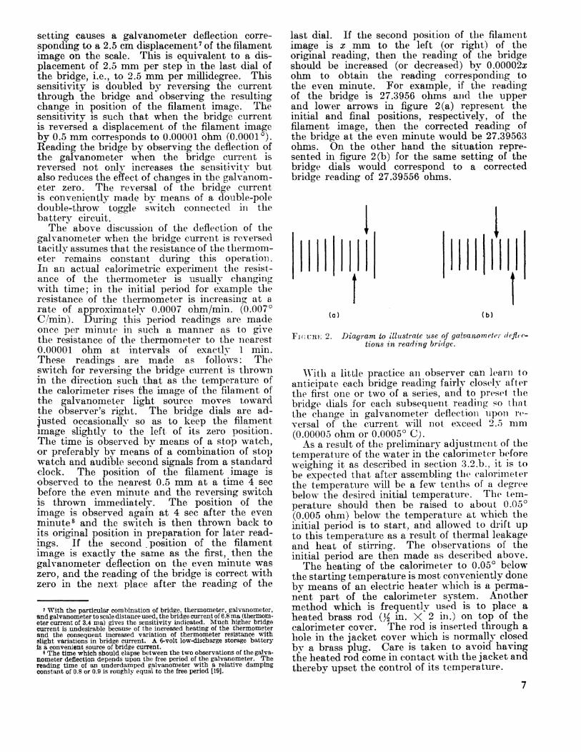
last dial. If the second position of the filament image is x mm to the left (or right) of the original reading, then the reading of the bridge should be increased (or decreased) by 0.00002x ohm to obtain the reading corresponding to the even minute. For example, if the reading of the bridge is 27.3956 ohms and the upper and lower arrows in figure 2 (a) represent the initial and final positions, respectively, of the filament image, then the corrected reading of the bridge at the even minute would be 27.39563 ohms. On the other hand the situation repre sented in figure 2(b) for the same setting of the bridge dials would correspond to a corrected bridge reading of 27.39556 ohms.
(a) (b)
FICCRF; 2. Diagram to illustrate use of galvanometer deflec tions in reading bridge.
With a little practice an observer can learn to anticipate each bridge reading fairly closely after the first one or two of a series, and to preset the bridge dials for each subsequent reading so that the change in galvanometer deflection upon re versal of the current will not exceed 2.5 mm (0.00005 ohm or 0.0005 C).
As a result of the preliminary adjustment of the temperature of the water in the calorimeter before weighing it as described in section 3.2.b., it is to be expected that after assembling the calorimeter the temperature will be a few tenths of a degree below the desired initial temperature. The tem perature should then be raised to about 0.05 (0.005 ohm) below the temperature at which the initial period is to start, and allowed to drift up to this temperature as a result of thermal leakage and heat of stirring. The observations of the initial period are then made as described above.
The heating of the calorimeter to 0.05 below the starting temperature is most conveniently done by means of an electric heater which is a perma nent part of the calorimeter system. Another method which is frequently used is to place a heated brass rod ()£ in. X 2 in.) on top of the calorimeter cover. The rod is inserted through a hole in the jacket cover which is normally closed by a brass plug. Care is taken to avoid having the heated rod come in contact with the jacket and thereby upset the control of its temperature.

The above instructions may be illustrated by an example. The calorimeter temperature before weighing was adjusted to a value such that after assembly of the calorimeter the thermometer read ing was 20.5 + 7.420 ohms. 9 By means of the heated rod referred to above, the temperature was raised until the reading of the bridge was 20.5 + 7.465 ohms. The rod was then removed, the plug replaced in the hole in the jacket, and the calo rimeter temperature allowed to drift upward until the bridge reading was 20.5 + 7.4701 ohms when the readings of the initial period were begun. These are made once per minute as indicated previously.
Immediately after the observations of the initial period are completed the charge of combustible in the bomb is ignited by means of an electric fuse, the sensitivity of the galvanometer is reduced by reducing the bridge current to about one-third of its original value, and the observations of the middle period are begun. These must be made so rapidly that there is no time for reversing the bridge* current for each observation. The ob servations arc made by setting the bridge dials successively at certain predetermined readings and observing the times at which the galvanometer de flection becomes zero. After about 3 min the rate of temperature rise has decreased to such an extent that the bridge current can be increased to its original value and the precise readings of resist ance each minute are resumed. These precise readings are continued until the rate of tempera ture change has been constant for at least 10 min. The observations made after the rate of tempera ture change has become constant constitute those of the final period.
TABLE 1. Observations of time and thermometer resistance during a bomb-calori metric experiment
Time minutes
01 2 3 45 6 6.528 6.621 6.682 6.754 6.820 6.894 6.970 7.066 7.170 7.320 7.3997.496
Resistance minus
27.5 ohms
0.47015 . 47078 .47142 .47206
. 47334
. 47397
.4900
.5100
.5300
.5500
. 5700
.5900
. 6100
.6300
.6500
.6700
.6800
.6900
Difference X 10*
636464
128 (64)1J8 (64) 63
Time minutes
7.614 7.747 7.922 9
1011 12 13 14 15 16 17 18 19 20 21 22 232425 26 27 28
Resistance minus
27.5 ohms
0 7000 7100 7200 75050 7592076270 76410 76470 76499 76515 76525 76534 76540 76546 76553 76560 76566
76586 76592 76599 76606
Difference X 10*
870350 140
00 29 16 10
9 6 6
7 6
20 W(<v(7)
7
Bridge readings made during the course of a typical bomb calorimetric experiment are given in table 1, and are shown graphically in figure 3. The values given for resistance represent the ob served resistance of the thermometer minus 27.5 ohms. The initial period extends from 2=0 to / = 6 min, the middle period from t=6 to Z=18 miri, and the final period from £=18 to t=2S min. The constancy of the differences between consecu tive readings in the initial and final periods is an indication that the system has attained a steady state. This is a necessary condition for the appli- cabilitj7 of the method given in section 5 for calcu lating the corrected temperature rise.
0.5 -
10 15 20
TIME, MINUTES
30
B The bridge has a 20.5-ohm coil in addition to the 10-, 20-, 30-ohin coils, etc., in the lOxlO-ohm decade (see appendix).
FIGURE 3. Bridge readings versus time in a bomb calori metric experiment.
In the particular experiment illustrated in table 1 and figure 3 the time readings during that part of the middle period from t=6 to £ = 9 min were made by means of an electric timer which prints the time at which the operator presses a button when he observes the galvanometer deflection to pass through zero. This instrument is a con venience and would be an important part of the equipment in measurements of extremely high precision. It is not a necessary part of the appa ratus for measurements of the precision aimed at in the procedures described in this Monograph. For such precision it is also not necessary to obtain as many readings in the middle period. It is sufficient to make three or four measurements in the range from 55 to 70 percent of the total tem perature rise, and to read the time to the nearest second (or the nearest 0.01 min) by means of a stopwatch.

The corrected temperature rise for the experi ment illustrated in table 1 and figure 3 is calcu lated in section 5.
d. Firing Energy
The quantity of energy used to fire the charge is the sum of the electric energy used to ignite the fuse plus the heat of combustion of the amount of fuse wire burned. The current for igniting the fuse is obtained from a small transformer with a secondary voltage of about 10. The total firing energy can be determined in a series of blank ex periments in which only the fuse wire is burned. In such experiments the temperature rise of the calorimeter is very small, and the initial tempera ture of the calorimeter should be very near that of the jacket. The rate of change of temperature in the initial and final periods will then be small, and the correction for thermal leakage will also be small.
When a 2-cm length of fuse wire is used in the manner described in the appendix it has been found that if the wire is burned completely 10 the firing energy is constant and equal to 5.2 cal. No appreciable error will result from using this value in any case where the same type of fuse is used, i.e., a 2-cm length of Parr fuse wire wound into a helix and attached to platinum leads. The firing energy in this case is only 0.05 percent of the en ergy normally produced in a combustion experi ment, and any error in the value 5.2 cal will largely cancel if this same value is used for both calibra tion experiments and measurements of heats of combustion, and if the temperature rise is about the same in the two kinds of experiment.
The most serious error likely to be encountered in accounting for the firing energy is that which may result from a short-circuit between the firing electrode and the bomb, either because of failure of the insulation around the electrode or because of moisture getting into the mica insulation inside of the bomb. This mica normally is wet by the acid solution formed in combustion and by the water introduced in washing the interior of the bomb after each experiment. It should be dried thoroughly before each experiment, and the insu lation should be tested before attaching the fuse to its platinum leads. An insulation resistance of less than 10* ohms usually indicates either mois ture in the insulation or some other failure of the insulating material which needs to be corrected. A "megger" or volt-ohmeter or other similar in strument may be used for testing the insulation resistance.
* Combustion of the fuse wire may not be complete in all blank experi ments to determine the firing energy, although it is practically always com plete when a sample of fuel is burned in the bomb. Blank experiments in which combustion of the fuse wire is incomplete should be rejected, or else a correction for the unburned wire should be applied.
e. Materials in Bomb
A calibration of the calorimeter yields a value for the energy equivalent E of the system as ac tually used, consisting of calorimeter vessel, stirrer, water, thermometer, bomb, and contents of the bomb at the beginning of the experiment. The calorimeter vessel, stirrer, mass of water, ther mometer, and bomb will ordinarily be unchanged from one experiment to another, and the crucible and amount of water placed in the bomb will also be constant. However, the mass of the platinum leads to the fuse, the mass of oxygen, and the mass and kind of combustible material may change from one experiment to another. The heat ca pacity of the largest amount of platinum wire in the bomb amounts to only 0.001 percent of the total energy equivalent of the system, so that variations in the amount of platinum wire are en tirely negligible. The mass of oxygen in the bomb is inversely proportional to absolute tem perature and directly proportional to absolute pressure. The temperature is measured to about 0.5 C at the time the oxygen is admitted to the bomb, by means of a mercurial thermometer with its bulb near the bomb. The pressure of the oxygen (about 30 atm~450 psi) is measured to the nearest 0.1 atm (1.5 psi) by means of a calibrated Bourdon gage.
The values of the energy equivalent E obtained in calibration experiments are reduced to the energy equivalent E8 of a standard calorimeter system consisting of the calorimeter vessel with cover, the standard mass of water, stirrer, ther mometer, and bomb containing 1 ml of water, the crucible, and oxygen under an absolute pressure of 30.0 atm at 28.0 C but no combus tible material. In a measurement of heat of combustion the energy equivalent Es of the standard calorimeter system is corrected for any excess of the oxygen pressure at 28 C over 30 atm and for the heat capacity of the charge of combustible.
The reduction of the observed E to the corre sponding value of Es , and vice versa, is discussed in section 5 on calculation of results.
f. Acids Formed in Combustion
Nitric acid is normally formed in the combus tion reaction from nitrogen either in the fuel sample itself or present as an impurity in the oxygen. If sulfur is present in the fuel, oxides of sulfur will be formed. These are entirely con verted to sulfuric acid if nitric acid is also formed. For this reason, if the fuel is known or suspected to contain a significant amount of sulfur, the air initially present in the bomb should not be flushed out with oxygen at the time oxygen is admitted to the bomb. The sulfur will then be all con verted to aqueous sulfuric acid, and therefore to a determinate final state.
The total acid formed in combustion is deter-

mined by washing the inner surface of the bomb with distilled water and titrating the washings against 0.1 N sodium hydroxide, using methyl orange as the indicator.
If both nitric and sulfuric acids are formed the total acid is determined by titration as before, and the sulfur is determined by analyzing the
bomb washings after titration, using the procedure described in ASTM Designation D129-58 [14]. The correction for nitric acid is 14.0 kcal/mole of acid formed. If sulfur is present in the fuel the total acid is corrected for as if it were all nitric acid, and an additional correction of 1,400 cal/g of sulfur is applied.
4. Summarized Directions for a Bomb-Calorimetric Experiment
Summarized directions will now be given for carrying out a bomb-calorimetric experiment with benzoic acid to determine the energy equivalent of the calorimeter. Following these directions there will be a brief discussion of the differences in procedure in an experiment to determine the heat of combustion of a fuel.
4.1. Preliminary Adjustment of ApparatusObserve the temperature of the oxygen purifier
and if necessary bring its temperature to 500 C. (Caution: The temperature and oxygen pressure should never be allowed to exceed values consist ent with safety with respect to the possibility of explosive failure of the purifier. The manufac turer's recommendations regarding safety precau tions should be adhered to rigidly.) Add water, if necessary, to fill the calorimeter jacket bath, bring its temperature to the desired standard value and put the thermostat into operation (see sec. 3.2.C.).
4.2. Preparation and Weighing of Sample of Benzoic Acid
\Yeigh out approximately an amount of benzoic acid somewhat in excess of 1.52 g n and compress it into a pellet. Weigh the pellet on a balance sensitive to about 0.01 g and adjust the weight, if necessary, to 1.52 0.01 g (see footnote 11) by scraping the pellet. Carefully remove any pow dered benzoic acid from the pellet by brushing. Weigh the crucible on the semimicro balance, first empty and then after placing the pellet of benzoic acid into it, following the procedure described in section 3.2.a.
4.3. Preparation of BombTest insulation resistance. If less than 106
ohms, dry mica or replace cone insulator.Attach fuse wire to platinum leads as described
in the appendix. 12 Measure 1.00 cm3 of distilled water into the bomb by means of a buret or pipet. Attach the crucible to its support in such a manner that the fuse is nearly touching the pellet of benzoic acid and assemble the bomb. Connect the bomb
to the oxygen cylinder through the purifier and admit oxygen to a pressure of approximately 30 atm. The oxygen should be admitted slowly so as not to cool the copper oxide in the oxygen purifier below the temperature at which it will oxidize combustible impurities in the oxygen. Close the valve in the oxygen line and open the needle valve on the bomb, allowing the oxygen to escape until the pressure is reduced to atmospheric. This procedure removes about 97 percent of the nitrogen in the air initially in the bomb. Refill the bomb to the pressure of approximately 30 atm, read and record the temperature and pressure, and discon nect the bomb from the oxygen tank. Attach the binding post (fig. 6(b)) with the lead wire to the terminal nut on the bomb.
4.4. Weighing of Calorimeter Plus WaterFill the calorimeter with water, adjust tempera
ture of water, and weigh calorimeter plus water as described in section 3.2.b.
4.5. Assembly of CalorimeterImmediately after the calorimeter is weighed
carry it to the jacket and place it in its proper position in the jacket space. Place the bomb in the calorimeter, 13 put the calorimeter cover in place and press it down until its lower surface is in contact with the water. These operations should be performed rapidly and as nearly as possible in the same manner and in the same length of time in all experiments. Complete the firing circuit by connecting the lead to the bomb electrode to the binding post provided for this purpose (fig. l.(c)) and connect the other lead (already attached to the other binding post) to the calorimeter vessel by means of the clip shown in figure l.(d) (see appendix). Close the jacket cover and connect the calorimeter stirrer to its driving shaft. Meas ure the jacket temperature to 0.001 C (0.0001 ohm) by means of the bridge and resistance ther mometer, then remove the thermometer from the jacket bath, dry it, and put it in place in the calorimeter.
'i The standard mass of benzoic acid should be such as to give a tempera ture rise of approximately 3 C. The mass used should be within 0.01 g of the standard mass.
" It may be convenient to do this while waiting for the attainment of temp erature equilibrium in the balance case in connection with weighing the sample of combustible.
10
13 The bomb should bf lowered into the calorimeter without touching the water with the fingers. This can be done by using some sort of hook on which the bomb can be hung and which can be removed after the bomb is in place. A hook made of a piece of brass or nichrome rod about He in. in diameter and bent into the form shown in fig. 6(f) has been found satisfactory for this pur pose with the Parr bomb. The hooked ends of the rod are inserted into holes on opposite sides of the screw cap of the bomb, and are easily removed after the bomb is in place. The amount of water which adheres to the hook when it is withdrawn from the calorimeter is negligible.
4.6. Adjustment of Initial Temperature of Calorimeter
Adjust the calorimeter temperature to 0.05 (0.005 ohm) below the starting temperature of the initial period, and allow it to drift up to the start ing temperature as described in section 3.2,c. The starting temperature (in calibration experi ments) always has the same value, which is so chosen that the final temperature of the calo rimeter after combustion will be at, or preferably a few hundredths of a degree below, the temperature of the jacket.
4.7. Observation of Temperature and Ignition of Sample
After the temperature of the calorimeter has been allowed to drift up to the starting tempera ture, make and record the readings of time and temperature of the initial period each minute as described in section 3.2.c. Immediately after the last reading of the initial period fire the charge by closing the circuit through the fuse in the bomb. Observe the ammeter in this circuit when the charge is fired. The reading of the ammeter should rise abruptly to about 5 amp and then drop almost instantly to zero. Failure of the current to drop immediately indicates a short circuit, and the charge will probably not be ignited, or if it is ignited the result of the experiment will be in error by an unknown amount because of the excess electrical energy. If the ignition takes place normally, make and record the observations of the middle and final periods as described in section 3.2.c. After the end of the final period remove the thermometer from the calorimeter, insert it in the jacket bath and measure the temperature of this bath to 0.001 . If the temperature control equip ment has been operating properly the jacket tem perature should remain constant to 0.005 or better during an experiment.
4.8. Analysis of Contents of Bomb
Remove the bomb from the calorimeter, dry it, open the needle valve and allow the gas to escape at a rate such as to reduce the pressure to atmos pheric in not less than 1 min. Then open the bomb and examine the interior for unburned carbon, which would indicate incomplete com bustion. If more than a slight trace of unburned carbon is found the experiment should be rejected. If no appreciable amount of unburned carbon is found wash all interior surfaces of the bomb with distilled water and collect the washings quanti tatively in a beaker. The quantity of the wash ings should preferably not exceed 150 ml. Ti trate the washings against a 0.1 TV solution of NaOH using methyl orange as the indicator. Calculate the correction for nitric acid as de scribed in section 5 on calculation of results.
The procedure in a measurement of heat of combustion follows the same steps outlined in paragraphs 4.1 to 4.8, with certain differences in individual steps as indicated below.
4.2.a. Preparation and Weighing of Sample of Fuel
If the material whose heat of combustion is to be determined is a sufficiently nonvolatile liquid, weigh the empty crucible by the method of substitution as described previously, decrease the weights on the pan with the crucible by the desired weight of sample, 14 and add the liquid drop-wise from a pipet until the weights plus sample plus crucible balance the tare weight on the opposite pan, Ordinarily this procedure will add more than the desired weight of sample, and the excess may be removed, for example, by dip ping the end of a fine glass capillary into the liquid. Great care should be taken "during the introduction of the sample into the crucible and making the final adjustment of the weight to avoid getting any of the sample on the outside of the crucible. The final weighing of crucible plus sample is carried out as described in section 3.2. a.
If the material whose heat of combustion is to be determined is a volatile liquid, the enclosure of the sample in a glass bulb (as described in the appendix) and the determination of its weight (as described in sec. 3.2.a.) will ordinarily have been done prior to the beginning of the calorimet- ric measurements. It is then only necessary to place the bulb in the crucible before starting the procedure described in section 4.3. and 4.3.a.
4.3.a. Preparation of Bomb
The procedure here is the same as that described in section 4.3 except that if the sample contains sulfur the air initially in the bomb is not flushed out before filling the bomb with oxygen. If the sample does not contain sulfur the air should be flushed out as described in section 4.3 by filling the bomb with oxygen to 30 atm, allowing the gas to escape until the pressure is reduced to atmospheric, and then refilling the bomb to 30 atm. Where the sample is enclosed in a glass bulb, premature breakage of the bulb when the pressure is first raised to 30 atm can sometimes be detected by the odor of the fuel in the escaping gas when the pressure is released.
4.6.a. Adjustment of Initial Temperature of Calorimeter
111 the case of a nonvolatile liquid where the weight of sample is such as to give a temperature rise equal to that in a calibration experiment the adjustment of the initial calorimeter tempera ture is carried out in the same manner as described in section 4.6.
u The weight of sample should be such a? to pive approximately the same temperature rise of the calorimeter as in the csiUbnition experiments.
11
In the case of volatile samples it is difficult to make the glass sample-bulbs sufficiently uniform in capacity to give the same temperature rise of the calorimeter in all experiments. Select the initial temperature for each experiment so that the mean of the initial and final temperatures of the calorimeter will be the same as in the calibra tion experiments.
4»S«a. Analysis of Contents of Bomb
If the sample contains no sulfur follow proce dure described in section 4.8. If the sample con tains sulfur titrate the bomb washings to deter mine total acid is described in section 4.8. After this titration analyze the bomb washings for sulfur using the procedure described in ASTM Designa tion D129-58 [14].
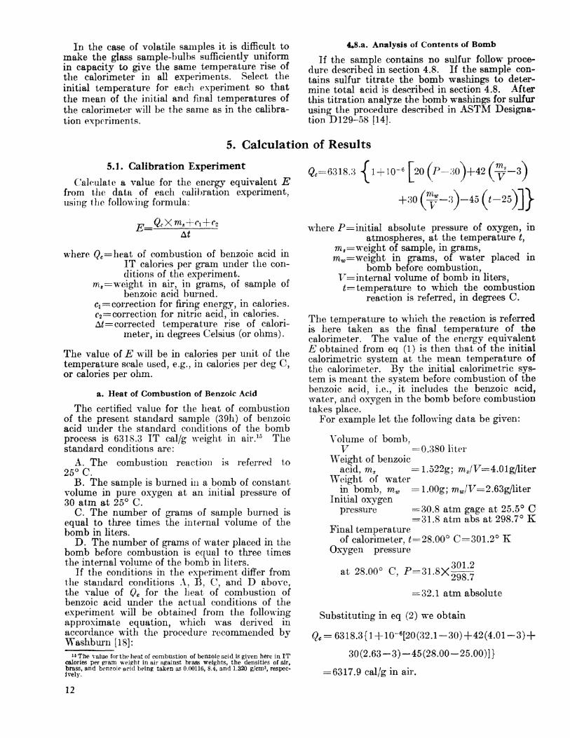
5. Calculation of Results5.1. Calibration Experiment
Calculate a value for the energy equivalent E from the data of each calibration experiment, using the following formula:
where (?c =heat of combustion of benzoic acid in IT calories per gram under the con ditions of the experiment.
m a =weight in air, in grams, of sample of benzoic acid burned.
Ci~ correction for firing energy, in calories.c2 =correction for nitric acid, in calories.A£=corrected temperature rise of calori
meter, in degrees Celsius (or ohms).
The value of E will be in calories per unit of the temperature scale used, e.g., in calories per deg C, or calories per ohm.
a. Heat of Combustion of Benzoic Acid
The certified value for the heat of combustion of the present standard sample (39h) of benzoic acid under the standard conditions of the bomb process is 6318.3 IT cal/g weight in air. 15 The standard conditions are:
A. The combustion reaction is referred to 25 C.
B. The sample is burned in a bomb of constant. volume in pure oxygen at an initial pressure of 30 atm at 25 C.
C. The number of grams of sample burned is equal to three times the internal volume of the bomb in liters.
D, The number of grains of water placed in the bomb before combustion is equal to three times the internal volume of the bomb in liters.
If the conditions in the experiment differ from the standard conditions A, B, C, and D above, the value of Qc for the heat of combustion of benzoic acid under the actual conditions of the experiment will be obtained from the following approximate equation, which was derived in accordance with the procedure recommended by Washburn [18]:
18 The value for the heat of combustion of benzoic acid is given here in IT calories per pram weight in air against brass weights, the densities of air, brass, and benzole acid being taken as 0.00116, 8,4, and 1.320 g/em3 , respec- ively.
&=6318.3
-a,
- 30\f 42^p?-
*-,)-« (,-*,)]}
where P=initial absolute pressure of oxygen, inatmospheres, at the temperature £,
ms =weight of sample, in grams, mw=weight in grams, of water placed in
bomb before combustion, V= internal volume of bomb in liters, t= temperature to which the combustion
reaction is referred, in degrees C.
The temperature to winch the reaction is referred is here taken as the final temperature of the calorimeter. The value of the energy equivalent E obtained from eq (1) is then that of the initial calorimetric system at the mean temperature of the calorimeter. By the initial calorimetric sys tem is meant the system before combustion of the benzoic acid, i.e., it includes the benzoic acid, water, and oxygen in the bomb before combustion takes place.
For example let the following data be given:
Volume of bomb,V =0.380 liter
Weight of benzoicacid, ms = 1.522g; mg/T7 4.01g/liter
Weight of w^aterin bomb, mw l.OOg; mw/V=2.63g/liter
Initial oxygenpressure =30.8 atm gage at 25.5 C
= 31.8 atm abs at 298.7 K Final temperature
of calorimeter, £=28,00 0=301.2 K Oxygen pressure
at 28.00 C, P=31.8X301.2298.7
= 32.1 atm absolute
Substituting in eq (2) we obtain
Qc = 6318.3(1 +10-6[20(32.1-30) +42(4.01-3) +
30(2.63-3)-45(28.00-25.00)]}
= 6317.9 cal/g in air.
12

b. Correction Terms Ci and c2
The correction c\ for firing energy is preferably determined in a series of blank experiments as de scribed in section 3.2.d. The use of the value d = 5.2 cal will not lead to a significant error if the fuse is a 2-cm length of Parr fuse wire wound into a helix and attached to platinum leads. In some cases a greater length (5 cm or more) of fuse wire is attached to electrodes which are located a short distance away from the crucible. In such cases the fuse may not all burn, and the firing energy will be different in different experiments depending upon the length of wire burned. If this procedure is followed, the length of wire burned in each experiment must be determined and the correction Ci may be taken as 2.6X£ calories, where L is the length of wire burned, in centimeters.
The correction c2 for nitric acid is 14.0 kcal/mole of nitric acid formed, or 14.0 N cal/cm3 of sodium hydroxide solution of normality N required to neutralize the acid. Thus if 2.4 cm3 of 0.0987 A7 sodium hydroxide is required to neutralize the nitric acid formed, c 2 ==2.4X 14.0X0.0987 = 3.3 cal.
c. Corrected Temperature Rise
The calculation of the corrected change in re sistance of the thermometer in a bomb calorimet- ric experiment will be illustrated by carrying out the calculations for the experiment in which the data given in table 1 were obtained. As stated in section 3.2.c. the initial, middle, and final peri ods in this experiment extend from t=Q to Z 6, 2=6 to £=18, and £=18 to £=28 min, respectively. The observed change in resistance of the ther mometer is taken as the difference between the bridge readings at £=6 and £=18 min, namely, 0.76540 0.47397 = 0.29143 ohm. This difference is to be corrected for thermal leakage and heat of stirring. Correct methods for calculating this correction will be found in reference [3] and in a number of the references there cited. For the accuracy aimed at in this manual it is sufficient to use the following procedure which has been found empirically to give correct results within about 0.01 percent of the total resistance change. We first calculate the average rates of change of resistance TI and r2 in the initial and final periods, respectively. These are seen to be
0.47397 0.47015 0.003826 6
=0.000637 ohm min
7*2 = -0.76606-0.76540 0.0006610 10 =0.000066 ohm min.
Next we calculate from the data of the middle period the time tm at which 63 percent of the ob served resistance change has taken place. The re sistance at tm is given by that at the final reading of the initial period (at £=6), 0.47397, plus 63 per cent of the observed resistance change. In other words
^=0.47397+0.63X0.29143=0.65757 ohm.
Referring to table 1 it is seen that this resistance is reached at a time intermediate between 7.17 and 7.32 min, and by interpolation we obtain £ ,= 7.227 min. The corrected initial and final re sistances, Ri (corr.) and Rf (corr.), are then ob tained by applying corrections to the observed resistance at £=6 and £=18 min as follows: 1 *
i (corr.)=#6
Rf
= 0.47397+0.000637 X 1.227=0.474752 ohm,
.)^^ (0bs)-r2 (18-£TO )
= 0.76540 0.000066X10.773 = 0.764689 ohm.
The change in resistance corrected for thermal leakage and heat of stirring is then
Ef (corr.) Bi (corr.) = 0.764689 0.474752=0.289937 ohm.
Practically the same result would have been ob tained if only three readings had been taken during the period of very rapid temperature rise, say at 5=0.6300, 0.6600, and 0.6900 ohm.
This result must be corrected for errors in the bridge coils by applying a correction equal to the algebraic sum of the certificate corrections to the coils used in obtaining RI$ (obs) less the algebraic sum of the corrections to the coils used in obtaining RQ (obs.). It is evident that it is not necessary in this calculation of the change in resistance to in clude corrections to coils which enter into both R6 (obs) and jR 18 (obs). In this case such coils in clude one of 20.5 ohms and one of 7 ohms. The bridge correction in the experiment under con sideration was +0.000029 ohm, making the cor rected resistance change AjR=0.289966 ohm.
Resistance of the thermometer can be converted to temperature with the aid of the formula or tables accompanying the NBS certificate for the thermometer. It is somewhat more convenient, however, to compute a table of factors A£/AB which when multiplied by the corrected change in resistance A# will give the desired change in tem perature A£. Such a table may be calculated as follows. First the temperatures corresponding to certain given resistances, say JR 27.5000, 27.6000, ... - 28.5000. . . , are calculated, using the data in the certificate for the thermometer. These tem peratures are then substituted into the formula
A£
! I * M< "I MOO lOOOOj
(3) 17
w Resistances are read to 1 in the fifth decimal. The calculations are carried one place farther to avoid errors from roimding off.
" Strictly speaking, eq (3) gives the derivative dt/dR. This is exactly equal to Af/AR for a finite interval AR, provided it is calculated for the mean tem perature of the interval. If, as is customary, the value of dt/dR corresponds to the mean resistance of a finite interval, then dt/dR is not exactly equal to A7/A.R, but the error is entirely negligible.
13

where RQ, a, and d are constants given in the cali bration certificate for the particular thermometer. The values of B arid corresponding values of Af/A7? calculated from the above formula are tabu lated. The value of At/&R to use in calculating the corrected temperature rise in a given experi ment is that corresponding to the mean of the corrected initial and final values of R for the experiment. This value of A//A7? is obtained from the table, by interpolation if necessary. For ex ample, in the example given above the value of A//A7? used should be mat corresponding to the mean of 27.5 + Rt (corr.) and 27.5 + 7?, (<*orr.) or
-28.1197 ohms. 18
It is found that AZ/A/? increases by about 0.03 percent for an increase in temperature of 1 deg C (0.1 ohm).
It is not necessary, however, to convert re sistance to temperature. If desired, the re sistance change can be taken as the measure of the temperature change, with the energy equiv alent E expressed in caloreis per ohm. The corrected resistance change AB (ohms) in a meas urement of heat of combustion would then be multiplied by K (calories per ohm) to give the energy (calories) produced in the combustion reaction. One disadvantage of this procedure is that E in calories per ohm changes more for a given change in the mean temperature of the experiment than does E in calories per degree. For a typical bomb calorimeter it has been calculated that the change in the value of E for an increase of one degree (0.1 ohm) in the mean temperature of the experiment is about +0.03 percent if E is expressed in calories per ohm, but is less than 0.01 percent if E is expressed in calories per degree. Hence if temperatures are expressed in ohms, then for a precision of 0.01 percent, the mean temperature of the calorimeter should be kept within about 0.2 degree (0.02 ohm) of some fixed value, or else the value of Es in each calibration experiment should be cor rected to some standard temperature, and the mean value of Es for this standard temperature should be corrected to the actual mean temper ature of each measurement of heat of combustion . The greater change with temperature of EB ex pressed in calories per ohm is due to the fact that the resistance of the thermometer is not a linear, function of temperature, i.e., the fact that At/AR is not constant.
A convenient check on the behavior of the calorimeter and the correctness of the temperature measurements may be obtained by calculating the "cooling constant/' k, of the calorimeter. This is defined by
w Strictly speaking, tho corrections to all the coils used should be applied In calculating the mean value of the resistance. In many cases, however, these corrections are too small to be significant in this calculation and may be neglected.
14
where rl and r2 are the average rates of change of resistance in the initial and final periods, respectively, and RI and 7?2 are the observed resistances at the mid-points of these periods. Thus, using the data of table 1 at the beginning of this section (5.1c):
0.000637 0.000066 = 0.76573 - 0.47206
=0.001944.
This quantity is a constant of the calorimeter and should remain constant to better than one percent in different experiments.
d. Example Illustrating the Calculations of E and E,
The calculation of E may be illustrated by an example, using the following data taken from preceding sections as indicated.
Weight benzoic acid, ms ~ 1.52188 g (sec. 3.2 a) Heat of combustion of benzoic acid, Qc =6317.9
cal/g (sec. 5.1.a) Firing energy (2 cm fuse wire), Ci=5.2 cal (sec.
5.1.b)Correction for nitric acid, c2 3.3 cal (sec. S.l.b) Corrected resistance change, A7?=0.289966 ohm
(sec. 5.1.c) Corrected temperature change, At=2.87462 deg
C (A*/AB=9.91364) Oxygen pressure at 28.0 , P=32.1 atm abs
(sec. 5.1.a)Substituting the above values in eq (1), the value
of E is found to be
E= 1.52188X6317.9+5.2+3.3 0.289966
1.52188X6317.9+5.2+3.3 2.87462
33188.7 cal/ohm
=3347.78 cal/deg.
To reduce the above values of E to the cor responding values of Es , the energy equivalent of the standard calorimeter system, it is only neces sary to subtract the heat capacity of the sample of benzoic acid, and of the amount of oxygen in excess of that required to fill the bomb to 30 atm absolute at 28 C, as follows:
Heat capacity of excess oxygen = (32. 1-30.0) X 0.077- ~
Value of S.._.._._ .-.. -_..
cal/ C
3, 347. 780.16 0.44
3,347.18
cal/ohm
33, 188. 71.6 4.4
33,182.7
The factor 0.077 used in calculating the correc tion for excess oxygen is the increase in heat capacity (in calories per degree) per atmosphere

increase in pressure in the bomb used, which has an internal volume of 0.380 liter. For a bomb of volume V the corresponding factor is 0.077 F/0.380. The factor 0.29 used in correcting for the benzole acid is the specific heat of benzoic acid in calories per gram degree Celsius. Both factors are greater by a factor of 10 if E is in calories per ohm (for a thermometer having a resistance of 25.5 ohms at 0 C).
5.2. Calculation of Heat of Combustion
Calculate a value of total (or gross) heat of combustion at constant volume from the data of each measurement, using the following formula.
Q, (4)
where:
Q, (gross) = total heat of combustion at constant volume at the final temperature of the experiment, in IT calories per gram.
E— energy equivalent of the calorimeter as used, in IT cal/deg (or IT cal/ohm)
At= corrected temperature rise of calorim eter in degrees (or ohms)
ra,=mass of sample, in grams
GI— firing energy, in calories
c2 = correction for energy of formation of nitric acid, in calories
c3 correction for energy of formation of sulfuric acid, in calories,
a. Energy Equivalent of Calorimeter as Used
The calorimeter as used differs from the stand ard calorimeter because it contains the sample of fuel and because, in general, the absolute pressure of the oxygen at 28 differs from 30.0 atm. The energy equivalent E of the calorimeter as used is obtained by adding to the energy equivalent Es of the standard calorimeter the heat capacity of the charge of combustible and the heat capacity of the oxygen in excess of that required to fill the bomb to 30.0 atm absolute at 28 C. The calcula tion is illustrated as follows, taking the sample of combustible as 0.92231 g of gasoline, and the oxygen pressure at 28.0 as 29.0 atm absolute:
Energy equivalent of standard calorimeter, E»— = Heat capacity of excess oxygen, (29.0-30.0) X0.077. = Heat capacity of sample, 0.922X0.51.._ ~~ «
Energy equivalent of calorimeter as used, E=
cal/ C
3, 347. 18 -.08+.47
3,347.57
cal/ohm
33, 182. 7 -0.8_1_A 7
33, 186. 6
The factor 0.51 used in calculating the heat capacity of the sample is the specific heat of gasoline 19 at 26.5 C in cal/g C. The factor 0.077 used in calculating the heat capacity of the excess oxygen is defined in section S.l.d. Both factors are greater by a factor of 10 if E9 is in calories per ohm (for a thermometer having a resistance of 25.5 ohms at 0 C). The heat capacity of the glass bulb (less than 0.1 g) used to enclose the sample of gasoline ma3r be neglected.
b. Corrected Temperature Rise
Directions for calculating the corrected temper ature rise are given in section 5.I.e. The value to be used in the example to be given later may be taken as 0.309617 ohm or 3.06943 C.
c. Corrections Ci, c2 , c*
The correction d for firing energy with a 2-cm length of fuse wire may be taken as 5.2 cal. The corrections c2 and c3 are calculated as follows: The correction c2 is calculated as if all the acid found by titration were nitric acid, as described in section 5.1.b. Thus if it required 14.2 ml of 0.0987 N sodium hydroxide to neutralize the total acid the correction c2 would be given by c2 = 14.2X14.0X0.0987=19.6 cal. If the test for sulfur showed 0.0042 g sulfur present in the bomb washings the correction for sulfuric acid, as given in section 3.2.f., would be c3 = 1400X0.0042 = 5.9 cal.
d. Calculation of Qv (gross)
Substituting the values of E in calories per degree (or calories per ohm), AZ (or AJff), GI, c2 , c3, and ms given in sections 5.2.a., b., and c. into formu la (4) yields:
Qv (gross) = 3347.57X3.06943-5.2-19.6-5.9 0.92231
or
Qv (gross) =33186.6X0.309617 5.2 19.6 5.9 0.92231
Both of these expressions yield the value 11107.4 cal/g weight in air for the total (or gross) heat of combustion of the liquid gasoline at constant volume. The corresponding value in terms of engineering units is
Qv (gross) = 11107.4XI.8 = 19993 Btu/lb.
The method of calculation is such that the value obtained for Qv (gross) is referred to the final temperature of the calorimeter, in this case 28.1 C. The observed value may be reduced to the standard temperature of 25 by means of the following formula:
w Taken from NBS Miscellaneous Publication M97 [15] for a gasoline having an API gravity of 70. Values of heat capacity of petroleum products given in this publication for a temperature of 80 F range from 0.42 to 0.52 for API gravities ranging from 10 to 80.
15

Qr (gross,25 C) = Qt (gross,/ 0 C) + A(t-25) (5)
Where the value of the factor A is given in the following table. 20
<>? (gross)
Etn lit}18,50018,60018,70018,80018,90019,00019, 1001 9, 20019,30019,40019,500
A
Jitu/lb0 C0.68.72.76.80.85.89.93.97
1.011.051.09
"v (pross)
Ptvllb19. 60019,70019,80019,90020, OW20, 10020, 20020, 30020, 40020, 50020, 600
A
Btv/K>° C.14.18.22.26.30.35.39
1,431.471.511.55
Substituting the value of Qv (gross, 28.1 C) = 19993 Btu/lb and the corresponding value -4=1.30 from the above table in eq (5) we obtain
Q, (gross, 25 C) = 19993 +1.30X3.1 = 19997 Btu/lb.
values of A werorailculu ted using the specific heats ofliquld petroleum fuels, of gaseous oxygen and carbon dioxide, and of liquid water. The masses of oiypen consumed and of carbon dioxide and water formed in combustion of unit mass of fuel were obtained from an empirical relation between Q, (gross) and hydrogen content. See reference [5]. In general, the change in Q,'gross (Btu/lb) with temperature for any fuel may be calculated from the relation oO, (gross)/df=A", (reactants) A', (products).Here A% (reactants) denotes the heat capacity at constant volume of 1 Ib of fuel plus the oxygen consumed in its combustion, and A% (products) denotes the heat capacity of the products of combustion of one pound of fuel, including gaseous carbon dioxide and liquid water. In calculating K, the heat capacities of solids and liquids may be taken as heat capacities at con stant pressure.
e. Calculation of Q v (net)
If the hydrogen content of the fuel is known the value of the net heat of combustion, 0T (net, 25 ), can be calculated from that for Qv (gross) by means of the following formula [4]:
<?„ (net, 25 C) = <?. (gross, 25 C)- (6) 91.23 (%H)
Thus if Q, (gross, 25 C) = 19997 Btu/lb arid (%H) = 13.9, we obtain
0P (net, 25 C) = 19997 91.23X13.9= 18729 Btu/lb.
If the hydrogen content of the fuel is not known, an approximate value for Op (net, 25 C) can be calculated from the following empirical relation:
Qp (net, 25 C) (7) =4310 + 0.7195 Q, (gross, 25 C).
Substituting the value Q, (gross, 25 C) = 19997 Btu/lb in this equation we obtain
Qp (net, 25 C)=4310+0.7195X19997= 18698 Btu/lb (approximate)
Equation (6) is preferable to eq (7) for calculating net from gross heat of combustion, since the latter equation is purely empirical. A fairly accurate value of (%H) is required in eq (6), since an error of 0.1 in this quantity introduces an error of about 0.05 percent in Qp (net).
6. References
[1] ASTM Method D 240-57T. ASTM Standards 7,143, (1958).
[2] ASTM Method D 271-58, ASTM Standards, 8,999 (1958).
[31 F. D. Rossini, Experimental thermochemistry (Inter- science Publishers, New York, N.Y., 1956), and the references there cited.
[4] R. S. Jessup and C. S. Cragoe, Nat. Advisory Comm. Aeronaut. Tech. Note No. 996 (1945) (copies not available).
[51 S. Rothberg and R. S. Jessup, Ind. Eng. Chem. 43,981 (1951).
[61 R. S. Jessup and J. A. Cogliano, ASTM Bull. No. 201(Oct. 1954).
[7] G. T. Armstrong, R. S. Jessup, and T. W. Mears,Chem. Eng. Data Ser. 3, 20 (1958).
[8] H. C. Dickinson, Bul. BS 11, 189 (1914) S230. [91 N. S. Osborne, H. F. Stimson, and T. S. Sligh, Bul.
BS20, 119 (1925) S503.[10] C. H. Meyers, J. Am. Chem. Soc. 45, 2135 (1923). [11] T. W. Richards and F. Barrv, J. Am. Chem. Soc. 37,
993 (1915).[12] H. N. Davis, Mech. Eng. 51, 791 (1929). [13] See for example:
(a) N. Irving Sax, Handbook of dangerous mate rials (Reinhold Publishing Corp., New York, N.Y., 1951).
16
(b) Manufacturing Chemists Association, General Safety Committee, Guide for safety in the chemical laboratory (D. Van Nostrand and Co., New York, N.Y., 1954).
(c) National Safety Council, Accident prevention manual for industrial operations (Chicago, 111., 1951).
(d) National Board of Fire Underwriters, National electrical code (Chicago, 111., 1940).
[14] ASTM Method D 129-58, ASTM Standards 8, 81 (1955).
[15] C. S. Cragoe, Thermal Properties of Petroleum Prod ucts, NBS Misc. Publ. M97 (this paper is out of print but may be found in many public libraries).
[16] E. J. Prosen and F. D. Rossini, J. Research NBS 27, 289 (1941) RP1420.
[17] J. Coops, D. Mulder, J. W. Dienske, and J. Smitten- berg, Rec. trav. chim. 66, 153 (1947).
[18] E. W. Washburn, J. Research NBS 10, 525 (1933) RP546; see also chapters 5 and 6 of reference [3],
[19] F. K. Harris, Electrical measurements, p. 57 (John Wiley & Sons, Inc., New York, N.Y., 1951).
[20] E. J. Prosen, W. H. Johnson, and Florence Y. Pergiel, J. Research NBS 62, 43 (1959) RP2927.

7. Appendix7.1. Apparatus
The major items of apparatus used in bomb- calorimetric measurements on fuels at the National Bureau of Standards are listed in table 2. On the basis of prices listed in manufacturers' catalogs at the present time (1959), the estimated total cost of replacement of the equipment listed is in the neighborhood of $15,000.
TABLE 2. Major items cf equipment used in measurement of heats of combustion of liquid fuels at the National Bureau of Standards
Mueller bridge. Resistance thermometer. Galvanometer.Calorimeter, jacket, and thermo
stat.Combustion bomb. Platinum crucibles and fittings. Balance.Bet of class M weights for above. Heavy duty balance
Set of weights for above.Oxygen purifier.Temperature controller for oxygen
purifier.Laboratory table for bridge. Laboratory bench. Pellet press. Reducing valve. Julius suspension.
The approximate arrangement of the calorimeter and accessory apparatus is shown in figure 4. The reading station R provides support for the lamp L and ground glass scale S, as well as for some elec trical equipment for measurements not covered in this Monograph. It also contains a convenient "desk" for use in recording the data of bomb calo- rimetric experiments. The arrangement of the equipment for purifying oxygen and admitting it to the bomb is shown schematically in figure 5.
The arrangements shown in figures 4 and 5 are not necessarily the best under all circumstances. For example, the bench BE (fig. 4) is considerably larger than necessary for the calorimeter alone, as part of this table is used for other purposes.
The essential features of the various items of apparatus are described below. Items not obtain able commercialhr , and modifications of com mercial items are described in considerable detail.
FIGURE 5. Arrangement of apparatus for admitting oxygen to bomb.
B, bomb; D, dryer; G, pressure gage; N, needle valve; O, oxygen cylinder; P, oxygen purifier; and K, reducing valve.
a. Bridge
The bridge used is a special Mueller bridge designed especially for bomb-calorimetric measure ments. It is substantially equivalent to the com mercially available bridge designated as 6-2. In addition to the usual 10-, 20-, 30-ohm coils of the lOXlO-ohm decade this bridge has a 20.5-ohm coil. Such a coil is useful in bomb-calorimetric measurements, where the change in resistance of the thermometer in an experiment is of the order of 0.3 ohm, since it makes it possible to avoid a change in setting of the dial of the 10Xl-obm decade which would otherwise be necessary in certain circumstances. Thus if the initial and final resistances of the thermometer are 27.8721
BR
BE
1 , 1 I 1 , 101 2345
FEET
FIGURE 4. Arrangement of calorimetric apparatus. BE, bench; C, calorimeter; BR, bridge; G, galvanometer; L, light source; M, stirring motor; R, reading station; and S, ground glass scale.
17

and 28.1806, the corresponding dial settings with the 20.5-ohm coil would be 20.5 + 7.3721 and 20.5 + 7.6806 and the change in dial setting would involve only the 10X0.1-ohm and lower decades. If no 20.5-ohm coil were available, it would be necessary to change the dial setting of the 10X1- ohm decade from 7 to 8 at a time when the tem perature of the calorimeter was rising very rapidly. This would greatly increase the difficulty of follow ing the temperature of the calorimeter during the period of rapid temperature rise, and might also involve a larger correction to the observed change in resistance of the thermometer.
b. Thermometer
The platinum resistance thermometer has a resistance of approximately 25.5 ohms at 0 C. It is of the strain-free type with coil windings very close to the wall of the enclosing glass tube. It was purchased under a specified requirement that the temperature of the coil with a current of 1 ma flowing through it should not exceed that of the bath in which the thermometer is immersed by more than 0.0003 C. Calorimetric resistance thermometers enclosed in metal sheaths are avail able commercially. These are less subject to breakage than glass-enclosed thermometers, but are subject to damage from bending the metal sheath. Such damage might not be obvious on casual examination, but could be detected by periodic determination of the ice point of the thermometer.
c. Galvanometer
The galvanometer has a sensitivity of about 0.2 ^v/rnm at 1 m, an external critical damping resistance of 40 ohms and a period of about 5 sec. The damping resistance used is so chosen that the galvanometer is slightly underdamped. The gal vanometer is protected from air currents and abrupt changes in temperature by an enclosure made of cork pipe covering (for 6 in. pipe) about 10 in. in outside diameter. The galvanometer is supported b3" a Julius suspension, which is very effective in reducing the effect of vibrations.
d. Bomb
The combustion bomb 21 is made of a corrosion- resistant alloy (Illium). It is provided with a check valve for admitting oxygen and also with a needle valve for releasing the gases contained in it. It is sealed by a self-sealing neoprene gasket. The original bomb has been modified by replacing the three supporting feet furnished with it by new ones of monel metal about 12 mm in height. This permits freer circulation of water under the bomb.
The base-metal electrode inside of the bomb, and the crucible-support rod were cut off leaving lengths of about 3 cm from the point at which they enter the lock nuts. To the shortened electrode
was hard soldered a }(e in. platinum rod about 3 cm in length. To the shortened crucible-support rod was hard soldered a 5-cm length of % in. o.d. platinum tube having a 0.01 in, wall. The ar rangement of electrode, crucible support, crucible, electric fuse and 0.3 mm platinum leads thereto is shown in figure 6(a) (valves not shown). An enlarged view of the platinum crucible is shown at (c) figure 6. The crucible is put in place by sliding the split tube (%* in. o.d.) shown at the right of figure 6(c) over the end of the % in. platinum crucible-support tube referred to above until the fuse is nearly in contact with the sample of combustible. The split tube may be deformed slightly with the fingers to make it fit the % in. tube tightly enough to be held in place by friction. The length of the crucible-support, and the posi tion of the crucible on this support should be such that the crucible cannot come in contact with the water in the bottom of the bomb when the bomb is assembled. If the crucible should come in contact with the water, combustion will be in complete.
21 Parr Instrument Company Catalog No. 1101.
18
FIGURE 6. Bomb and accessories.(a) Bomb, showing arrangement of crucible, crucible support, electrode,
etc. (Valves not shown, see fig. 1); (b) Binding post and lead wire; (c) En larged view of crucible; (d) Platinum lead flattened at end; (e) Fuse wire attached to platinum leads; and (f) Hook for handling bomb.
A supply of platinum lead wire is wound around the electrode and crucible support rods as shown, and a sufficient amount of this to reach down to the crucible is unwound for each experiment. The electric fuse is a 2-cm length of Parr fuse wire (No. 34 AWG chrome! C) which is formed into a small helix by winding it around a rod about 0.04 in. in diameter. The method of attaching the fuse to the platinum leads is illustrated at (d) and (e), figure 6. The ends of the lead wires are first flattened by hammering as shown at (d). The flattened ends are then bent and the fuse inserted as shown at (e), after which the turned-up ends

of the lead wires are hammered down with a small hammer or squeezed together with pliers to clamp the ends of the fuse wires.
The terminal nut attached to the electrode out side of the bomb was replaced by one of the form shown at (a), figure 6. The binding post shown at (b), figure 6, has a split tube at its lower end which can be slipped over the upper part of the terminal nut, where it fits tightly so as to make good electrical contact. The lead wire shown at (b), figure 6, connects this binding post to one on the calorimeter jacket which is connected in the firing circuit. This wire is soldered to spade-type terminals at each end, the larger of which normally is permanently attached to the binding post shown at (b). This wire should be so insulated as to avoid any electrical contact with the calorimeter vessel. With alternating current the contact of the lead wire and bomb electrode with the water in the calorimeter does not result in any appre ciable electrical leakage, provided actual metallic contact with the calorimeter vessel is avoided.
e. Calorimeter and JacketThe calorimeter now used for fuel testing is of
the type described by Dickinson [8]. The calo rimeter vessel is of the form shown at (a) and (b), figure 1. The calorimeter cover is in the form of a flat circular disk with vertical wall about 1 cm in height at the edge. The holes OT and OL (fig. l(b)) are surrounded by metal collars about 1 cm high. The cover fits tightly enough inside of the calorimeter vessel so that it is held in place by friction. Its lower surface is in contact with the water of the calorimeter. The calorimeter vessel is supported inside of the jacket by pins of stain less steel, in the manner described by DickinsonM-
The Dickinson type calorimeter was constructed in the NBS shops. There is a commercially avail able "submarine" calorimeter, 22 based on a design developed at the National Bureau of Standards [20], which has been found to be substantially equivalent in performance to the Dickinson calo rimeter. The submarine calorimeter is supplied without a thermostat for the jacket bath, so that a thermostat for controlling the bath temperature to a few thousandths of a degree must be purchased or constructed.
The thermostat 23 used with the particular Dick inson type calorimeter used for fuel testing is similar to one previously described by Osborne, Stimson, and Sligh [9], It consists of a "bulb" filled with toluene and connected to a glass capil lary U-tube (1.5 mm i.d.) containing mercury. Expansion of the toluene as a result of rising teiii-
22 Catalog Xo. 63090, Precision Scientific Co., Chicago, 111. This calorim eter embodies an improved method of supporting the calorimeter vessel inside of the jacket [20].
23 Temperature-control units for which a control accuracy of 0.001 C. is claimed are available commercially. Numerous other temperature-control devices are described in the literature. See for example the papers cited in reference [3], For any temperature-control unit it is important that the rela tive locations of heater, stirrer, and temperature-sensing element should be as shown in figure 1, that is, the bath liquid should flow from the heater, through the stirrinpr propeller, and over the temperature-sensitive element by the shortest path possible.
perature causes the mercury to make contact with a needle closing an electrical circuit through an electronic relay 24 which shuts off the current in the electric heater in the jacket bath. The "bulb" TB (fig. 1) consists of about 3 m of % 6 in. copper tubing with 0.01 in. wall thickness wound into a helix and so located in the same tubular housing as the jacket bath stirrer that the water flows over the bulb immediately after leaving the stirrer. The glass U-tube and attached valve for admitting or removing toluene are shown in figure 7. The valve has tubular openings at the top and bottom for attaching the reservoir B and the capillary U-tube as described below.
INCHES
FIGURE 7. Valve and glass parts of thermostat.V, valve; TB, tube to thermostat bulb; B, toluene reservoir; F, capillary
U-tube; E, enlargement in capillary; H, platiuum wire; L, leads to relay; C, Fyrex tube; D, brass cap; S, screw; and N, steel needle.
The Pyrex reservoir B contains a supply of toluene which is separated from that in the "bulb" TB (fig. 1) by the valve V when it is closed. This valve is opened when the calorimeter is shut down thus permitting toluene to flow from the reservoir into the bulb as the bath cools. Failure to open the valve when the bath cools usually results in air being drawn into the system through the capillary F (fig. 7). The Pyrex bulb C (fig. 7) also contains toluene which protects the mercury surface in the capillary from oxidation. The en largement E in the capillary is larger in volume than the mercury in the capillary so that no mer cury will be drawn into the metal parts of the system if the valve V is inadvertently left closed when the calorimeter is shut down.
2* American Instrument Company Catalog Xo. 4-5301.
19
Electrical connection between the Valve V and the mercury in the capillary U-tube is provided by a platinum wire 77, long enough to reach from the top of the capillary to near the bottom of the U. The upper end of the wire is flattened and bent at a right angle to the rest of the wire so as to insure electrical contact with the valve.
The glass reservoir B and the capillary glass U- tube are soldered into the tubular openings in the brass valve V with pure tin following the procedure described by Meyers [10].
To fill the thermostat with toluene the tube C (with cap I) removed) is connected to a large bulb G above C (at least 250 cm3 , not shown in fig- 7) by means of a short piece of Tygon tubing. Somewhat more than enough toluene to fill the thermostat is placed in the bulb G, and some is also placed in the reservoir B. Air can be removed from the thermostat system by heating the "bulb" (TB, fig. 1) to about 100 C and repeatedly evacuating the bulb G above the toluene and then admitting air. To test for air in the system, air is admitted above the toluene in 6r, the valve V is opened, the toluene meniscus is brought into the capillary at F, and the valve is closed. If the system is free of air, moderate air pressure applied by mouth above the toluene will not cause a movement of the meniscus in the capil lary of more than 0.2 or 0.3 mm. The removal of air from the system should be done before introducing mercury into the capillary. If air is inadvertently admitted to the system after mercury has been introduced into the capillary, the mercury should be removed before attempting to remove the air.
In preparing for a calorimetric experiment the jacket is first heated to the desired temperature, the heating current is reduced to slightly more than enough to maintain the temperature con stant, and the valve V is closed. Final adjust ment of the temperature can be made by moving the needle A^ up or down by rotating the cap D relative to the screw S (fig. 7). The heating current should be adjusted so that the on and off periods are about equal in length.
The method of bringing the firing leads through the jacket is illustrated in figure l(e).25 Two metal rods, one of which is shown at /?, are ce mented with wax into tubes T which pass through the jacket, so that the rods are insulated from the jacket. Each rod is drilled and tapped at each end for a 4-40 brass screw, which is used to clamp the terminal of the lead wire between the two washers, Tlr, thus forming a binding post at each end of the rod. The terminal at the left end of the lead wire shown in figure l(d) is attached per manently to one of the inner binding posts and the clip at the other end of the wire (d) is slipped over the edge of the calorimeter vessel when it is
35 This method is not applicable to some types of calorimeters, for example, submarine calorimeters. The important feature of the method is that the leads are in good thermal contact with the jacket, but are electrically insulated from it.
20
assembled preparatory to making an experiment. The other lead wire, from the binding post on the bomb (see fig. 6(b)), is attached to the other inner binding post after the bomb has been put in the calorimeter and the calorimeter cover has been put in place. The two outer binding posts are connected through an ammeter and a switch to a small transformer having a secondary voltage of 8 or 10. The switch should be of the momentary contact push-button type normally open except when held closed by the operator.
f. Balance for Weighing Samples
The balance used for weighing samples of com bustibles is an undamped semimicro balance (capacity 100 g) having a sensitivity reciprocal of 0.14 mg per division on the index scale. The balance is provided with a keyboard arrangement for adding and removing weights from 1 to 100 mg. Temperature gradients parallel to the balance beam are reduced by covering the walls of the balance case inside and out with aluminum foil, and bjr locating the balance where temperature gradients in the room are small. It has been found, however, that best results are obtained with the balance when there is a vertical temper ature gradient such that the top of the balance case is warmer by 0.03 to 0.1 C than the bottom.
The weights used with the balance are high- grade one-piece (class M) weights and were cali brated in the Mass and Scale Section of the National Bureau of Standards.
For most purposes a good analytical balance would be satisfactory if provided with high grade calibrated weights, and properly used.
g. Balance for Weighing Calorimeter
This is a magnetically damped heavy duty balance having a capacity of 5 kg and a sensitivity of about 0.5 mg. The tantalum-plated weights used with this balance are of good quality but are not calibrated. Calibration was considered unnecessary since the purpose of weighing the calorimeter is not to determine its absolute weight, but to reproduce the same weight of calorimeter plus water for each experiment. For this purpose it is important that the weights remain constant in value, and that the same weights be used at all times, but the actual masses of the weights used need not be known accurately.
h. Oxygen Purifier
Combustible impurities in the ox}^geii are re moved by passing it through a cylinder containing cupric oxide maintained at a temperature of 500 C (932 F). The purifier 26 consists essen tially of a heavy-walled alloy-steel cylinder having inside dimensions of approximately 1 in. diameter by 10 in. length, and capable of withstanding a pressure of at least 2500 psi at 500 C. The cylinder is provided with an electric heater. It
26 American Instrument Company 1942 Catalog No. 406-31.
has inlet and outlet at opposite ends, and a well for inserting a thermocouple for measurement of temperature. The cylinder is filled with wire-form cupric oxide. The temperature and oxygen pres sure in the purifier should not be allowed to rise above values consistent with safety. The manu facturers recommendations regarding safety pre cautions should be adhered to rigidly. The strength of materials decreases rapidly with in creasing temperature.
The temperature of the purifier can be con trolled by means of a "Fail safe" controller. Such controllers are available commercially.27 The pressure is easily controlled by a reducing valve attached to the oxygen cylinder.
i. Laboratory Table for Bridge
This table should be large enough to accom modate the bridge comfortably, and of a height which will afford convenience in the manipulation of the bridge dials. A table 22 in. square by 18 in. high is convenient for use with a G-2 bridge as it allows space for batteries, etc
j. Pressure Gage
The Bourdon pressure gage used has a 6 in. dial and is graduated from 0 to 800 psi in steps of 10 psi, so that it can be read to about 1 or 2 psi. The gage was calibrated in the Mechanical Instru ments Section of the NBS and was set so as to read correctly at 450 psi.
7.2. Glass Sample Bulbs
For measurements of heat of combustion of kerosenes, gasolines, or other volatile liquids it is necessary, in order to permit accurate weigh ing of the sample and to insure that it is all in the liquid state until it is ignited in the bomb, to enclose the sample in a thin-walled glass bulb, so constructed and filled that it will not break under the pressure of the oxygen. The type of bulb 28 used in testing of volatile fuels at the National Bureau of Standards, and the method of making such bulbs are illustrated in figure 8. Attempts to obtain bulbs of this type from manu facturers of glass laboratory apparatus have been unsuccessful to date, and such bulbs are therefore made in our own laboratory. A brief description of the method of making the bulbs will be given below. It should be recognized, however, that it is virtually impossible to describe the method in such detail as to enable an inexperienced worker to make bulbs successfully on his first attempt. The best that can be done is to outline the method, and to depend upon the individual worker to develop the necessary techniques by trial. It is to be expected that in the early attempts failures will far outweigh successes, and that a reasonable degree of skill can be acquired only by long and patient practice.
17 For example American Instrument Company Catalog No. 49-9570. Arthur S. Lapine and Company Catalog No. 357-70.
« Bulbs of this type were first described by Richards and Barry [11].
The starting material for making bulbs is soft glass tubing 4 to 6 mm in outside diameter.29 Approximately 2 cm of such a tube is heated in a moderately hot air-gas flame of an ordinary laboratory blast burner. When the glass becomes soft it is removed from the flame and drawn down to a fine capillary having a minimum outside diameter of about 1 mm. This procedure is then repeated in such a manner as to leave a short section of the same diameter as that of the original tube, as shown at figure 8(a). The two capillaries are then broken at about their midpoints, leaving a piece such as that shown at figure 8(b). The remaining glass-working operations are carried out with an air-gas micro blast burner capable of producing relatively small flames. Using such a micro burner the piece illustrated at (b), figure 8, is rotated and heated by a small hot flame at the point indicated by the arrows, and is then drawn down to 1 mm outside diameter. This procedure is repeated on the other side of the enlargement in the tube, the final product being as illustrated at(c), figure 8. This piece is then rotated and heated by a small sharp flame at the center of the enlarge ment as indicated by the arrow at (c), and the two halves of the piece are pulled apart as shown at (d), figure 8, where the enlarged end of the piece at the left has been reduced in size by removal of surplus glass. This removal of surplus glass is accomplished by heating the end of the enlarge ment until it softens, and then pulling off small filaments of glass until an enlargement of the proper size remains. After such removal of surplus glass from both of the pieces shown at(d) a spherical bulb, not greater than 14 mm in diameter, is blown on each piece (fig. 8(e)). The spherical bulb is then flattened on one side by holding the bulb above a small soft flame (no primary air) about Y4 in. in diameter by % in. high, and gradually lowering it until the glass on the under side of the bulb softens and flattens. This procedure is then repeated so as to flatten the opposite side of the bulb. The final form of the bulb is shown at figure 8(f), The operations of bringing the bulb down on to the flame and removing it after flattening is complete should be done gradually, since too rapid heating or cooling of the bulb may cause it to break.
The most difficult part of the procedure just described is that of blowing a bulb of the proper size. Success in this operation depends in part upon having the proper amount of glass on the end of the tube (fig. 8 (d)) and in part upon the type of flame used, as well as upon the procedure followed in blowing the bulb. A flame which has been found to be satisfactory is one about % in. in diameter by % in. in height with just enough primary air so that there is a small yellow tip in the flame. The end of the tube (fig. 8(d)) on which the bulb is to be blown is heated in the
80 Pyrex glass has been found unsatisfactory for this purpose, as tinburned carbon is usually found on such glass after a combustion. This may be related to the fact that the Pyrex glass does not melt completely when the sample is burned, as does soft glass, and therefore partially retains its original form, thus inhibiting access of oxygen to the fuel.
21
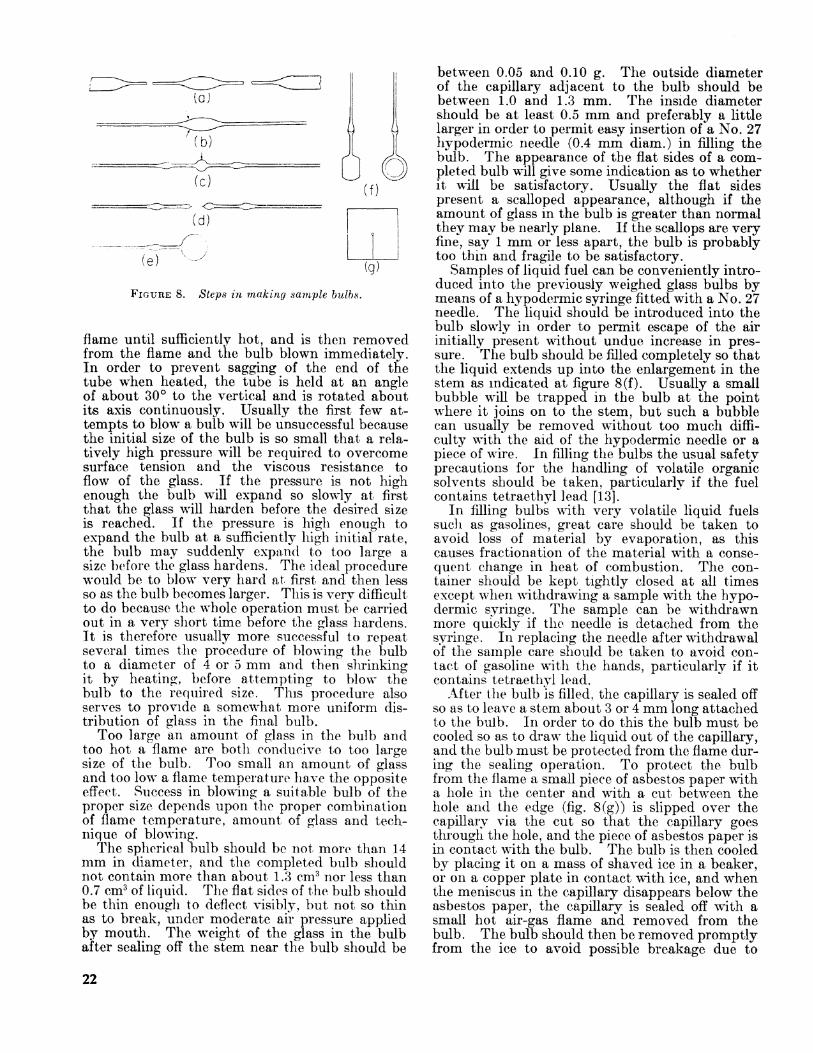
FIGURE 8. Steps in making sample bulbs.
flame until sufficiently hot, and is then removed from the flame and the bulb blown immediately. In order to prevent sagging of the end of the tube when heated, the tube is held at an angle of about 30 to the vertical and is rotated about its axis continuously. Usually the first few at tempts to blow a bulb will be unsuccessful because the initial size of the bulb is so small that a rela tively high pressure will be required to overcome surface tension and the viscous resistance to flow of the glass. If the pressure is not high enough the bulb will expand so slowly at first that the glass will harden before the desired size is reached. If the pressure is high enough to expand the bulb at a sufficiently high initial rate, the bulb may suddenly expand to too large a size before the glass hardens. The ideal procedure would be to blow very hard at first and then less so as the bulb becomes larger. This is very difficult to do because the whole operation must be carried out in a very short time before the glass hardens. It is therefore usually more successful to repeat several times the procedure of blowing the bulb to a diameter of 4 or 5 mm and then shrinking it by heating, before attempting to blow the bulb to the required size. This procedure also serves to provide a somewhat more uniform dis tribution of glass in the final bulb.
Too large an amount of glass in the bulb and too hot a flame are both conducive to too large size of the bulb. Too small an amount of glass and too low a flame temperature have the opposite effect. Success in blowing a suitable bulb of the proper size depends upon the proper combination of flame temperature, amount of glass and tech nique of blowing.
The spherical bulb should be not more than 14 mm in diameter, and the completed bulb should not contain more than about 1.3 cm3 nor less than 0.7 cm3 of liquid. The flat sides of the bulb should be thin enough to deflect visibly, but not so thin as to break, under moderate air pressure applied by mouth. The weight of the glass in the bulb after sealing off the stem near the bulb should be
between 0.05 and 0.10 g. The outside diameter of the capillary adjacent to the bulb should be between 1.0 and 1.3 mm. The inside diameter should be at least 0.5 mm and preferably a little larger in order to permit easy insertion of a No. 27 hypodermic needle (0.4 mm diam.) in filling the bulb. The appearance of the flat sides of a com pleted bulb will give some indication as to whether it will be satisfactory. Usually the flat sides present a scalloped appearance, although if the amount of glass in the bulb is greater than normal they may be nearly plane. If the scallops are very fine, say 1 mm or less apart, the bulb is probably too thin and fragile to be satisfactory.
Samples of liquid fuel can be conveniently intro duced into the previously weighed glass bulbs by means of a hypodermic syringe fitted with a No. 27 needle. The liquid should be introduced into the bulb slowly in order to permit escape of the air initially present without undue increase in pres sure. The bulb should be filled completely so that the liquid extends up into the enlargement in the stem as indicated at figure 8(f). Usually a small bubble will be trapped in the bulb at the point where it joins on to the stem, but such a bubble can usually be removed without too much diffi culty with the aid of the hypodermic needle or a piece of wire. In filling the bulbs the usual safety precautions for the handling of volatile organic solvents should be taken, particularly if the fuel contains tetraethj^l lead [13].
In filling bulbs with very volatile liquid fuels such as gasolines, great care should be taken to avoid loss of material by evaporation, as this causes fractionation of the material with a conse quent change in heat of combustion. The con tainer should be kept tightly closed at all times except when withdrawing a sample with the hypo dermic syringe. The sample can be withdrawn more quickly if the needle is detached from the syringe. In replacing the needle after withdrawal of the sample care should be taken to avoid con tact of gasoline with the hands, particularly if it contains tetraethyl lead.
After the bulb is filled, the capillary is sealed off so as to leave a stem about 3 or 4 mm long attached to the bulb. In order to do this the bulb must be cooled so as to draw the liquid out of the capillary, and the bulb must be protected from the flame dur ing the sealing operation. To protect the bulb from the flame a small piece of asbestos paper with a hole in the center and with a cut between the hole and the edge (fig. 8(g)) is slipped over the capillary via the cut so that the capillary goes through the hole, and the piece of asbestos paper is in contact with the bulb. The bulb is then cooled by placing it on a mass of shaved ice in a beaker, or on a copper plate in contact with ice, and when the meniscus in the capillary disappears below the asbestos paper, the capillary is sealed off with a small hot air-gas flame and removed from the bulb. The bulb should then be removed promptly from the ice to avoid possible breakage due to
22
excessive contraction of the liquid. The filled bulb is conveniently handled by the short project ing capillary by means of forceps of the type ordi narily used for handling balance weights. Parti- cles of asbestos which may adhere to the bulb should be removed by means of a camel's hair brush. Any liquid remaining in the capillary detached from the bulb in sealing it should be re moved before weighing the filled bulb together with this detached capillary. If the liquid is sufficiently volatile it can be removed by flaming the capillary several times with the micro-burner flame. The flame should be applied first to the closed end of the capillary, and moved gradually to the open end in such a manner as to avoid sof tening the glass. If the liquid is of low volatility,
it should be washed out with a volatile solvent, such as benzene or petroleum ether, introduced into the capillary by means of a hypodermic syr inge before flaming as described above.
When first sealed, the bulb may contain a small bubble of air. This will dissolve in the liquid after a time leaving the bulb completely filled with liquid. Bulbs prepared in the manner described should withstand changes in room temperature of 10 C or more, and pressures of at least 30 atm (450 psi) without breaking.
Glass sample bulbs of different types have been described by a number of workers [16, 17].
WASHINGTON, April 14, 1959.
23U.S. GOVERNMENT PRINTING OFFICE: I960


l^^The scope of activities of the National Bureau of Standards at its major laboratories, in Washington, D.CM and Boulder, Colo., is suggested in the following listing of the divisions ami sections engaged in technical work. In general, each section carries out specialized research, development, and engi neering in the field indicated by its title, A brief description of the activities, and of the resultant publications, appears on the inside front cover.
, IXC*Electricity and Electronics. Resistance and Reactance. Electron Devices* Electrical Instru
ments. Magnetic Measurements. Dielectrics. Engineering Electronics. Electronic Instru mentation. Electrochemistry.
Optics and Metrology. Photometry and Colorimetry. Optical Instruments. Photographic Tech nology . Length. Engineering Metrology.
Heat. Temperature Physics. Thermodynamics. Cryogenic Physics. Rheology. MolecularKinetics. Free Radicals Research.
Atomic and Radiation Physics. Spectroscopy. Radiometry. Mass Spectrometry. Solid StatePhysics. Electron Physics. Atomic Physics* Neutron Physics. Radiation Theory. Radio activity. X-ray. High Energy Radiation. Nucleonic Instrumentation. Radiological Equip ment.
Chemistry. Organic Coatings. Surface Chemistry. Organic Chemistry. Analytical Chemistry.Inorganic Chemistry. Electrodepoeition. Molecular Structure and Properties of Gases.Physical Chemistry. Thermochemistry. Spectrochemistry* Pure Substances.
Mechanics. Sound* Mechanical Instruments* Fluid Mechanics. Engineering Mechanics. Massand Scale. Capacity, Density, and Fluid Meters. Combustion Controls.
Organic and Fibrous Materials. Rubber. Textiles. Paper. Leather. Testing and Specifi cations. Polymer Structure. Plastics. Dental Research.
Metallurgy. Thermal Metallurgy. Chemical Metallurgy. Mechanical Metallurgy. Corrosion.Metal Physics.
Mineral Products. Engineering Ceramics. Class. Refractories. Enameled Metals. Consti tution and Microstmcture.
Building Technology. Structural Engineering. Fire Protection. Air Conditioning. Heatingand Refrigeration. Floor, Roof, and Wall Coverings. Codes and Safety Standards. HeatTransfer. Concreting Materials.
Applied Mathematics. Numerical Analysis. Computation. Statistical Engineering. Mathe matical Physics.
Data Processing Systems. SEAC Engineering Group. Components and Techniques. DigitalCircuitry. Digital Systems. Analog Systems. Applications Engineering.
* Office of Basic Instrumentation. • Office of Weights and Measures.
BOULDER, COLORADO
Cryogenic Engineering. Cryogenic Equipment. Cryogenic Processes. Properties of Materials.Gas Liquefaction.
Radio Propagation Physics. Upper Atmosphere Research. Ionosphere Research. RegularPrediction Services. Sun -Earth Relationships. VHF Research. Radio Warning Services,AirgJow and Aurora. Radio Astronomy and Arctic Propagation.
Radio Propagation Engineering. Data Reduction Instrumentation. Radio Noise. Tropo-spheric Measurements* Trophoepheric Analysis. Propagation-Terrain Effects. Radio-Mete*orology. Lower Atmosphere Physics.
Radio Standards. High-Frequency Electrical Standards. Radio Broadcast Service. Radio andMicrowave Materials. Electronic Calibration Center. Microwave Physics. MicrowaveCircuit Standards.
Radio Communication and Systems. Low Frequency and Very Low Frequency Research.High Frecjuency and Very High Frequency Research. Modulation Systems. Antenna Research.Navigation Systems. Systems Analysis Field Operations,


![Heats-of-combustion and of formation of the normal paraffin ......Rossini] HeatsofCombustionandFormation 23 bondswere practicallyidentical withthevalues computedfrom heats of combustion](https://static.fdocuments.us/doc/165x107/6111b98bf85435279f15c57f/heats-of-combustion-and-of-formation-of-the-normal-paraffin-rossini-heatsofcombustionandformation.jpg)


