Precip'itatio Phenomena: Deformation and · PDF filePrecip'itatio Phenomena: Deformation and...
117
Precip'itatio Phenomena: Deformation and Aging Edited by B.N.Doy L.ZLECTEpv ,Approved ffm L r~ Distributior n~ r World Materials Congress 7988 Published by
Transcript of Precip'itatio Phenomena: Deformation and · PDF filePrecip'itatio Phenomena: Deformation and...

Precip'itatioPhenomena:Deformation andAgingEdited by B.N.Doy
L.ZLECTEpv
,Approved ffm L r~
Distributior n~ r
World Materials Congress7988 Published by

PRECIPITATION PHENOMENA:DEFORMATION AND AGING
Proceedings of an International Conferenceheld in conjunction with the
1988 World Materials CongressChicago, Illinois, USA24-30 September 1988
Edited byB. N. Dey
Sponsored byASM INTERNATIONAL'S Materials Sciences Division,
Annealing and Recovery Committee
Published by

The publication of this Conference Proceedings of the 1988 WorldMaterials Congress has been made possible by the generouscontribution of ELETROMETAL S.A.
Copyright© 1988byASM INTERNATIONALTMAll Rights Reserved
No part of this book may be reproduced, stored in a retrieval system,or transmitted, in any form or by any means, electronic, mechanicalphotocopying, recording, or otherwise, without the prior writtenpermission of the publisher. No warranties, express or implied, aregiven in connection with the accuracy or completeness of thispublication and no responsibility can be taken for any claims thatmay arise.
Nothing contained in this book is to be construed as a grant of anyright or manufacture, sale, or use in connection with any method,process, apparatus, product, or composition, whether or not covered byletters patent or registered trademark, nor as a defense against liabilityfor the infringement of letters patent or registered trademark.
Library of Congress Catalog Card Number 88-071671ISBN: 0-87170-338-6SAN: 204-7586
Printed in the United States of America

UNCLASS I FI EDSECURITY CLASSIFICATION OF THIS PAGE ("on Data Entered)
REPORT DOCUMENTATION PAGE READ INSTRUCTIONSBEFORE COMPLETE4 G FORM
1. REPORT NUMBER 12. GOVT ACCESSION NO. 3. RECIPiENT'S CATALOG NUMBER
AO25297.I-MS-CF N/A N/AAN/A
4. TITLS_(and Subtitle) S. TYPE OF REPORT & PERICD COVERED
1988 World Materials Congress Proceedings Final
1 Ort 87 - 31 Mnr 89
24-30 Sep 88, Chicago Eight Volumes 6. PERFORMING ORG. REPORT NUMBER
N/A7. AUTHOR(&) S. CONTRACT oR GRANT NUMBER(.)
S. G. Fishman and A. K. Dhingra, editors DAAL3-87-G-0128
9. PERFORMING ORGANIZATION NAME AND ADDRESS 10. PROGRAM ELEMENT, PROJECT. TASK
AREA & WORK UNIT NUMBERS
ASM International
Detroit, MI 4820Z N/A
1I. CONTROLLING OFFICE NAME AND ADDRESS 12. REPORT DATE
U. S. Army Research Office 1988
P. 0. Box 12211 13. NUMBER OF PAGES
Researh Tri nnl P~ r, Nr 977Q14. MONITORING AGENC-Y NAME & ADORESSQdf' erent from Controling Office) IS. SECURITY CLASS. (of this report)
Unclassified
ISa. DECLASSIFICATION/DOWNGRADINGSCHEDULE
16. DISTRIBUTION STATEMENT (of ehi. Report)
Submitted for announcement only.
17. DISTRIBUTION STATEMENT (of the abetract entered In Block 20, It different from Report)
IS. SUPPLEMENTARY NOTES
The view, opinions, and/or findings contained in this report are
those of the author(s) and should not be construed as an official
Department of the Army position, policy, or decision, unless so
designated by other documentation.19. KEY WORDS (Continue on reveree elde if noceseary nd Identify by block number)
Composites, Sheet Steels, Electronic Materials, Wear Resistance,
Precipitation Phenomena, High Integrity Castings, Inclusions, HSLA Steels
20. A§$RACT"rct=a - ,revoe id f .eas-, wd Identify by block nusnber)
The proceedings of the 1988 World Materials Congress were pu liIed
by ASM and consits of the following volumes:
,"I Microalloyed HSLA Sttels Conference Proceedings / --
2. Inclusions and Their Influence on Material Behavior
3. High Integrity Castings /
&4. ' IPrecipitation Phenomena: Deformation and Aging,
5;/ Wear Resistance of Metals and Alloys (over)
D O F O R M 1 4 7 3 -o o r YP eor a s sM O V S I S S O L E T L A S I F I F
O CLAS,IICATOM OF r AIS PAGE 0(W.n D.ataEntered)

SECURITY CLASSIFICATION OF THIS PAGE(Wlen
Date Entered)
.-ABSTRACT CONTINUED:
6, Electionic Materials and Processing
7 Corrosion-Resistant Automotive Sheet Steels/
8 Cast Reinforced Metal Composites
SD
SECURITY CLASSIFICATION OF THIS PAGE(Wh e ~n Damta Entered)

Program OrganizerBiswa N. Dey, SUNY, Utica, New York 13504
Chief Session ChairmanBiswa N. Dey, SUNY, Utica, New York 13504
Session Chairmen
Session 1: Y. I. Ustinovshikov, Division of Academy of Sciences, Izhevsk, USSRJ. E. Flinn, Idaho National Engineering Laboratories, Idaho Falls, Idaho
Session 2: H. Zhou, Xi'an Jiaotong University, Xian Shaanxi Province, The People'sRepublic of China
F. D. S. Marquis, South Dakota School of Mines, Rapid City, South Dakota
Session 3: E. M. P. Silva, Universidae Federal de Minas Gerais, Belo Horizonte,MG Brazil
C. S. Pande, Naval Research Laboratories, Washington, DC
Session 4: E. Szpunar, 05-230 Kobylka, K. Warszawy, ul. Modrzewskiego 2A PolandD. Atteridge, Oregon Graduate Center, Beaverton, Oregon
T I C
GOPYINSPECTE19
6
NTiS ."3
Sold by: - - --ASM International.....9639 Kinsman RoadMetals Park, OH 44073 ' -Price:
12 2. or
"' ,S !; :2-020

PREFACE
The articles included in this publication are from a program on precipitating alloys, mostlyferrous. These interesting investigations are of immense value for both nuclear and non-nuclear applications. The papers deal with the effects of aging and deformation, in theoryand experiments. Because of time limitation, not all the papers intended for presentation atthe conference, could be included In this publication. I am thankful to all the presenters,who have made this international conference possible. I am also grateful to all chairmen ofthe sessions for kindly agreeing to help for the smooth running of the program. I amthankful to all members of the sponsoring committee for their encouragements. I wish tothank also, my wife Gouri, my daughter Jhilmil and my son Spondon, for their patientassistance in collecting and reorganizing many sections of the edited manuscripts to fulfillour goal of the planned publication.
B. N. DeySeptember 1988Chicago
v

TABLE OF CONTENTS
Precipitation Phenomena: Deformation and Aging-A Phenomenal Affair ............... 1B. N. Dey
Effects of Prior and Simultaneous Deformation on the Sensitization of AusteniticStainless Steels ................................................................ 3
A. Advani, D. Atteridge, S. M. Bruemmer
Static Recrystallization of Cold Deformed Austenitic and Ferritic Stainless Steels ........ 19R. Barbosa, D. B. Santos
Effect of Precipitation of Secondary Phases in 17-14-2 Austenitic Chromium-Nickel-Molybdenum Steels on the Evolution of Low-Cycle Fatigue Cracking ............. 25
E. Szpunar, J. Wawszczak
Aging Behavior of Double Quenched and Cold Worked Multiphase Stainless Steels ....... 35F. D. S. Marquis, S. F. Wang, J. Qadri, M. Hadji, M. N. Datar
Precipitating of Second Phase in Solid Solutions .................................... 53Yu. I. Ustinovshikov
Thermomechanical Treatment of an Fe-Mn-AI-C Sideband Alloy ........................ 69K. H. Han, T. S. Kang, D. E. Laughlin
The Effect of Warm Rolling and Intercritical Annealing on the Microstructure of aH S LA S teel .................................................................... 77
R. Barbosa, D. B. Santos
Strain-Aging of Low.Carbon Martensite ............................................ 83Y. Li, G. Yu, H. Zhou
Deformation and Aging Behaviors of Low Activation Stainless Steel Composites ......... 91F. D. S. Marquis, M. Hadji, N. AroonKiatkong, R. Bhatnagar
Influence of Dynamic Strain Aging on the Work Hardening of a Fe-Mn-Al Steel in theTemperature Range 20 to 7000C ................................................... 107
C. Godoy, B. Gonzalez, P. R. Cetlin, E. M. de Paula e Silva
VII
PRECIPITATION PHENOMENA: DEFORMATION AND AGING-A PHENOMENAL AFFAIR
B. N. DeySUNY
Utica, New York, USA
Precipitation processes in alloys, early stage of aging and results inboth ferrous and non-ferrous, are the formation of a great number ofextremely important for strengthen- sub-electronmicroscopic solute atoming mechanisms in alloys and their clusters;structural applications in chemical, ii) Zone formation: the process innuclear and non-nuclear industrips, which Guinier-Preston zones growas well as other high technology following initial clustering, andareas. hardening as well as x-ray diffrac-
Age-hardening alloys have been tion effects take place. The harden-a subject of extensive studies in ing effects has been attributed tothe past since Wilm (1911) first the transition structures, which whenobserved it in 1906 and Merica et al transform to the equilibrium phases(1920) followed up with other cause softening. Handling straininvestigations. About seven decades causing increase in the internalearlier, Karsten (1939) discovered friction of furnace-cooled Al alloysone of the ingredients, viz. inter- testifies to this latter casemetallics, which are interrelated (Dey, 1965).with the precipitation processes. Cold working, both prior to and
Dreoipit-i-n may be '?fined a, after precipitation hardening treat-
the decomposition of a solid sol- ments is - matter of intrinsic intpr-ution (the parent matrix) into a est, as the changing concentrationnew phase of different composition of imperfections affect both the(the precipitate) and the initial precipitation and the reactionsolid solution with diminished temperature. Physical, mechanicalsolute concentration (depleted and other behaviors of the alloys arematrix). Changes in the physical extrpmely Qensiti!'e tn the deforma-properties (such as resistivity, tion and subsequent processes.etc.) chemical properties (such as Minor plastic deformation immediatelycorrosion, etc.) and the mechanical after quenching increased the hard-properties, such as hardness, damp- ness of an Al alloy (Graf and Guiniering and so on, accompany precipita- 1954). Studies of different sortstion (see Christian, 1974; involving carbide precipitationsSmoluchowski, 1951; Ustinovhikov, and effect of deformations have been1938; Dey, 1965, 1965, 1986). reported during the last thirty yearsOn aging some precipitating alloys (Ustinovshikov, 1984, 1985). Also,after quenching from their solution continuous and cyclic deformationtreatment temperature, two processes research with the help of modern dayusually occur before the equili- technology has shed new light intobrium phases are finally formed: both the theory and the actual ob-i) Clustering: the process which, servations of ferrous and non-accompanied by a marked change in ferrous precipitating systems. Thethe electrical properties an! by following papers will undoubtedlyenergy release-occurs at the very show the current state of the affair.

CHRISTIAN, J. W., The Theory of Trans-formation in Metals and Alloys,Pergamon (1974)
DEY, B. N.. J. Phys. Soc. (Japan), 20533 (1965)Canad. J. Phys. 43, 1347 (1965)in "Role of Interfaces in MaterialDamping", ASM,(1986)
GRAF, R. AND GUINIER A., Compt. Rend.238, 819, (1954)
KARSTEN, K., Pogg. Ann. 46, 160 (1839)MERICA, P., Waltenburg, R. G., ANDSCOTT, H., Trans AIME, 64, 41 (1920)SMOLUCtIOWSKI, R., Phase Transformation
in Solids, Wiley and Chapman (1951)USTINOVSHIKOV, Y., Precipitation in
Solids, Sci. Press (Moscow) (1988)Met. Sci., 18, 337 (1984)
WILM, A., Metallurgic, 8, 225 (1911)
2

EFFECTS OF PRIOR AND SIMULTANEOUS DEFORMATIONON THE SENSITIZATION OF
AUSTENITIC STAINLESS STEELS
Ashok H. Advani, David G. AtteridgeOregon Graduate Center
Beaverton, Oregon 97006-1999, USA
Stephen M. BruemmerBattelle-Northwest
Richland, Washington 99352, USA
ABSTRACT environments (e.g., high-temperatureoxygenated water). This susceptibility is
The presence of prior or simultaneous caused by a change in the grain boundarydeformation results in an acceleration in the microchemistry which occurs when thekinetics and, perhaps, an alteration in the material is heat treated in, or slow cooledthermodynamics of sensitization. This has through, a particular temperature rangebeen observed in a study on the effects of (500-9000 C).prior and simultaneous strain on the The primary composition changeprecipitation of carbides and development of involved is the depletion of chromium insensitization in Types 304 and 316 austenitic the region adjacent to the grain boundarystainless steels. Samples were strained to caused by grain boundar recipitation ofdifferent levels using standard and chromium-rich carbides.T-o Chromiumspecifically designed variable strain tensile depletion (or sensitization) depends on aspecimens. Carbide precipitation and critical balance between the thermo-sensitization behavior was examined using dynamics of carbide precipitation andanalytical electron microscopy (AEM) and kinetics of chromium diffusion. Thus,electrochemical potentlokinetic reactivation variables affecting this critical balance(EPR) tests. control the sensitization response of the
The extent to which the kinetics of material.sensitization is accelerated depends directly Plastic deformation has been known toon the amount of strain present in the be a key variable affecting rates ofmaterial. Specimens subjected to increasing reactions occurring in materials. Reactionstrain levels sensitize at shorter times and thermodynamics and kinetics, for example,achieve higher degree of sensitization (DOS) may be modified by the deformationvalues. Lower chromium minimums and wider, process.7 Sensitization development is,asymmetric chromium-depletion profiles have likewise, altered by the presence ofalso been observed (using AEM) in strained strain. 1,8- 18 However, limited dataversus unstrained samples. Asymmetric exists to quantify the effects of strainingdepletion profiles are associated with on sensitization development. This data isselected grain boundaries where strain-induced vital to understanding the effects ofgrain boundary migration has taken place. thermomechanical processing and fabrica-Carbides on these grain boundaries tend to tion on the sensitization phenomena.extend preferentially into one grain instead In this work, a systematic study hasof growing as thin, flat plates as found on been carried out to evaluate the effect ofunstrained boundaries. straining prior to, or during, isothermal
treatment on the sensitization response ofINTRODUCTION Types 304 and 316 austenitic SS. Degree
of sensitization has been measured usingStainless steels (SS) are susceptible to indirect electrochemical and direct
Intergranular (I) corrosion and stress analytical methods.corrosion cracking (SCC) in certain aqueous
3

EXPERIMENTAL PROCEDURE treatments were performed using variabletime steps out to a total time of 100 hours
MATERIALS - High carbon, Types 304 and at 6250C. Sensitization measurements were316 stainless steel heats were used to made on the material after each heatexamine the effects of deformation on treatment step.sensitization. The composition of the heats The effects of uniaxial deformationare given in Table 1. All heats were received during isothermal treatment wasin the mill processed condition and solution investigated using flat, dogbone-shapedannealed (1100°C/1 hour) before subsequent tensile specimens. Specimens were deformedexperimentation. Solution annealed specimen at constant extension rates varying from Igrain sizes were found to vary from 110 to to 6% strain per hour. Isothermal heating150um. was attained using a clamshell furnace
DEFORMATION SPECIMENS - Three types of surrounding the tensile specimens.deformation tests were performed. They Unstrained specimens were attached to theconsisted of two types of prior deformation gage secticn of the tensile specimentests and one type of simultaneous deformation during heat treatment to ensure that thetest. Prior deformation specimens were control specimens were subjected to anstrained at ambient temperature prior to identical thermal history. Temperaturesisothermal exposure while simultaneous were measured along the gage section duringdeformation specimens were subjected to heat treatment and were found to be withincontinuous deformation at a set strain rate 50C of the specified 6000 C for these tests.during isothermal exposure. Initial isothermal exposure durations were
One type of prior deformation specimens between 0.5 and 1 hour at 6000C. Largerwere given a selected prior strain and then exposure times were subsequently used tosubjected to an interrupted, additive achieve total test times between 5 andIsothermal heat treatment cycle. These 15 hours. Degree of sensitizationspecimens were fabricated from high-carbon measurements were carried out after eachType 316 SS and were used to determine the isothermal exposure.effect of the magnitude of single-step prior The multistep prior deformation teststrain on sensitization development. The and control specimen configurations weresecond type of prior deformation specimens the same as those used for the simultane-were fabricated from high-carbon Type 304 and ously strained specimens. The multistep316 SS and were subjected to ambient straining specimens were deformed at ambientat a fixed strain rate between each heat temperature at strain rates comparable totreating step of an interrupted, additive those used at elevated temperature for theisothermal heat treatment cycle, simultaneously strained specimens. The
Strain magnitude effects of prior magnitude of strain for each ambient strain(single-step) deformation on sensitization cycle was similar to that received by thewere investigated using a specifically respective simultaneously strained specimendesigned, variable strain tensile specimen. during its next thermal cycle. Therefore,The specimen was flat, 300mm in length and had the strain magnitude received by multistepa width varying from approximately 25 to prior and simultaneously strained specimens7.5mm along a gage length of 175mm. Ambient deformed at the same strain rate wereuniaxial tensile testing on this specimen similar at the end of each respectiveproduced a range of strains from 0 to 40% heating cycle. This was done to enable aprior to necking. Strains were estimated by more direct comparison between prior andmarking the gage at 12.5mm intervals and simultaneous deformation. DOS measurementsmeasuring the reduction in cross sectional were made after each isothermal exposureareas at each interval. step and prior to the next straining step.
Sections corresponding to 0.4, 2.8, 8.5, SENSITIZATION MEASUREMENT -13.5, and 30% average strain were cut from the Sensitization response of the differentvariable strain specimen. These were then specimens was measured using the EPR test.aged alongside an unstrained, annealed EPR tests were performed using the methodspecimen at 6250C. Incremental heat proposed by Clarke.19- 21 The EPR test has
Table 1 - Bulk Compositions and Grain Sizes of Stainless Steel Heats
AISI Heat C Cr Ni Mo Mn Si P S N B3 C-6 0.062 197 8.75 0 1.72 67 67" 67 0065 ---
C-7 0.072 18.53 9.33 0.43 1.74 0.46 0.046 0.017 0.036 ---316 SS-16 0.058 17.11 11.43 2.16 1.77 0.41 0.014 0.005 0.008 0.002
4

been shown to be a reliable, quantitative results in EPR-DOS values higher than thatmethod of measuring the DOS for a SS material of the 13.5% strain sample. The data,and can be related to grain boundary chromium however, has not been used for quantitativedepletion.5 ,6 analysis due to the presence of
The laboratory variation of the EPR test intragranular attack.was used to determine DOS for the single-step The acceleration of sensitization withprior deformation specimens. The field deformation illustrates the criticalvariation of the EPR test was used to importance of thermomechanical, not justdetermine DOS for the multistep prior and thermal, effects on sensitizationsimultaneous deformation tests. These test development. An increase in the prestrainvariations have been found to produce level is observed to decrease the "time toequivalent results.22 ,23 Experimental sensitize" the Type 316 heat (time to reachparameters employed are summarized in an EPR value of 5 C/cm 2 ) (Fig 3). This canTable 2. be assumed to reflect a reduction in
chromium carbide nucleation time as aTable 2 - Experimental Parameters for EPR function of strain present in the material.
Tests The presence of strain prior to thesensitization heat treatment also has a
Instrument: Instruspec* Model WC-5 pronounced effect on the rate at which theElectrolyte: 0.5 M H2SO4 + 0.01 M KSCN DOS value increases after initial sensi-
at 300C tization. Acceleration of sensitizationSpecimen kinetics appears to be a direct function of
Preparation: I-Pm Diamond Polish the applied strain. Deformation inducedPassivation accelerated sensitization development has
Conditions: Potential of 0.2V (SCE) also been observed by otherfor 2 minutes investigators.8- 18
Reactivation Differences in sensitization kineticsScan Rate: 6V/hour (AISI 304 SS) with increasing deformation has been
3V/hour (AISI 316 SS) postulated to be due to increased disloca-tion density with strain, thereby enhancing
*Registered Trademark dislocation pipe diffusion of chromium. Ifthe effective chromium diffusivity is a
In addition to the indirect EPR method function of mobile dislocations, then theof detecting sensitization development, density of dislocations created by thelimited direct examination of changes in grain straining process will control chromiumboundary microchemistry (using AEM) were also diffusion, which in turn controls carbidemade. Samples were mechanically thinned (to growth, depletion width and DOS. Hart hasless than 150m) and subsequently jet polished proposed a relation to account for changesusing a solution of 3 volume percent in diffusivity of substitutional impuritiesperchloric acid in methanol. Examination of with changes in dislocation density.25
grain boundary microchemistry was made using a This relation has been quantified toPhilips EM 400T scanning transmission electron account for dislocation density effects onmicroscope (STEM) equipped with an ultra- chromium diffusivity in austenitic SS.1 I
thin window, energy dispersive x-ray A near-linear increase in dislocationdetector. Quantification of x-ray spectra density with strain has been observed bywas made using the Cliff-Lorimer the authors after 100 hours of ageing attechnique.24 6250C (Fig 4). The plot depicts a markedly
higher dislocation density for the 13.51RESULTS AND DISCUSSION strain specimen, as compared to the
annealed (unstrained) specimen, and canPRIOR DEFORMATION EFFECTS ON explain the acceleration in kinetics of
SENSITIZATION - The presence of strain prior sensitization. Measurement of dislocationto heat treatment sharply accelerated density valuea in as-strained specimens issensitization development. Specimens strained being carried out to obtain a moreto levels greater than 1% were observed to fundamental under- standing of stre'sensitize more rapidly and achieve higher DOS effects on chromium diffusivity a-values than unstrained specimens with sensitization development in auste.itic SS.identical heat treatment schedules (Fig 1). Optical micrographs (Fig 5) after EPRThe DOS value after 100 hours of exposure was tests corroborate the changes in DOS foundfound to more than double due to the presence after 10 hours of exposure, as seen inof 13.5% prior strain. Fig 6. The extent of grain boundary attack
Prior deformation appears to linearly after 10 hours of ageing at 6250C was seenincrease DOS, at least after 100 hours of to increase with increasing strain level upexposure at 6250 C and up to a strain level of to about 201 strain, while extensive13.51 (Fig 2). Deforming to 30% strain level intragranular attack is seen on specimens
5

with strains greater than 20%. Observation of deformation rate can be explained bythis nature have also been made in the work of changes in chromium diffusivity caused byPednekar et al,13 and other researchers.13 -17 enhanced dislocation pipe diffusion of
Increasing grain boundary attack as a chromium.function of strain suggests that deformation Grain boundary carbide precipitationcan promote a more uniform development of and chromium depletion characteristics werechromium depletion along grain boundaries in examined on strained and unstrainedmuch shorter exposure times than thermal Type 304 SS specimens. Bright field TEMexposure qlone. Continuous depletion along micrographs are shown in the top of Fig 10grain boundaries is often referred to as a for the C-7 specimen after 9 hours atprerequisite for IGSCC. The presence of EPR 6000C. EPR results for this specimen wereattack within the grains, noted at higher presented in Fig 7a. A deformation rate ofstrain levels, may be beneficial in that it 6% per hour produces an accumulated straindecreases available carbon for IG of more than 50%. This damage isprecipitation and may, therefore, decrease reflected in the high dislocation densitysensitization. which can be seen in the bright-field image
SIMULTANEOUS DEFORMATION EFFECTS ON (upper right, Fig 10). Dislocations areSENSITIZATION - Simultaneous straining also continuously created with time during thedramatically accelerated sensitization simultaneous deformation process leading todevelopment. Measurable DOS is observed in a continuously increasing dislocationshorter times, and EPR-DOS reaches higher density during isothermal exposure.values during additive 6000C anneals-in Grain boundary carbide morphologiesstrained versus unstrained specimens. are also quite different between theSensitization response as a function of beat strained and unstrained samples. Carbidestreatment time is documented in Fig 7 for the are elongated along the boundaries in thetwo Type 304 stainless steels (Heats C-6 and isothermal case, but extend preferentiallyC-7) for a strain rate of 6%/hour. Large EPR- into one grain with deformation. Not allDOS values (>10 C/cm 2) can be noted after only boundaries exhibit this appearance. It is1 hour at 6000C in the deformed specimens, probable that only interfaces which arewhereas more than 9 hours were required to properly oriented with the applied uniaxialapproach a comparable EPR-DOS in the control stress are influenced. Deformation mayspecimens. EPR-DOS values of more than promote discontinuous carbide growth due to35 C/cm 2 are observed after 9 hours for the short-circuit diffusion paths created byC-6 strained specimen versus only about the influx of dislocations. Discontinuous5 C/cm2 for the unstrained specimen. or cellular precipitation involves grain
Differences of this magnitude boundary diffusion and migration. Betrabetsubstantiate the critical importance of et al.2b have documented discontinuousthermomechanical effects oL sensitization precipitation of Cr23C6 carbides indevelopment. A simple isothermal heat Type 304 SS after isothermal heattreatment of many hours at 6000 C does not treatments.result in significant attack in the EPR test, Discontinuous carbide precipitationonly isolated regions along some grain mechanisms whether interface-energyboundaries are ditched. On the other hand, driven27 28 or chemically driven 29 will
strained specimens show almost continuous lead to the formation of asymmetricgrain boundary attack after only one hour at chromium depletion profiles. Precipitation6000C. resulting from volume diffusion where grain
Additional simultaneous strain boundary migration does not occur willexperiments were conducted on the C-6 SS to create nearly symmetric profiles.determine the effect of deformation rate on Chromium depletion was mapped for boththe sensitization development. Specimens strained and unstrained specimens.were deformed at a rate of 1 and 3% strain per Consistent with its much larger EPR-DOS,hour and compared to the 6% results. Sensi- the strained specimens exhibited lowertization kinetics scaled consistently with chromium minimums and wider depletionincreasing deformation rate, as shown in widths. Depletion profile characteristicsFig 8. After 9 hours, EPR-DOS is about 7, 15, for the two C-7 specimens are illustrated23, and 35 for deformation rates of 0, 1, 3, in the lower portion of Fig 10.and 6% per hour. Data for all four isothermal Differences in symmetry between thecontrol (unstrained) specimens are also two profiles can be noted with the strainedplotted in Fig 8 to give some indication of specimen's profile skewed to one side ofthe data scatter in these measurements. the interface. Depletion extendsDecreasing "time to sensitize" (EPR = 5 preferentially into the same grain as notedC/cm 2 ) observed with increasing strain rate for carbide growth. Chromium minimums were(Fig 9) also indicate a decrease in measured at about 8 wt% for the strainednucleation time with increasing deformation, versus 13 wt% for the unstrained specimen.These differences in kinetics with increasing The measured minimum for the deformed SS at
6

6000C is about 2 wt% lower than that observed simultane- ously strained specimen doesfor an isothermally treated specimen at 6000 C, tend to promote slightly larger EPR-DOS asregardless of heat treatment time.5 time at temperature is increased. The
The asymmetry in depletion profiles of difference is, however, not thoughtstrained specimens typically results in the significant. In fact, the oppositeminimum chromium concentration being measured behavior, when comparing multistep priorsome distance from the grain boundary. and simultaneous strain, is demonstrated inMinimum chromium was found to be about 20 to Fig 12b for the Type 304 heat. Prior30 nm from the interface as demonstrated for deformation rates of 3% strain per hourthe C-7 specimen in Fig 10. Grain boundary resulted in larger EPR-DOS at all times.migration appears to be a key in the Detailed conclusions cannot be made fromaccelerated sensitization kinetics. It these few comparisons, but do indicateshould be noted that asymmetric chromium that prior or simultaneous deformationdepletion profiles caused by grain boundary promote similar acceleration of sensi-migration are also possible in isothermal, tization kinetics. This may imply thatunstrained specimens. Their development is, changes in density of dislocations due tohowever, after significantly longer ageing simultaneous straining during heattimes, and the presence of strain appears to treatment are similar to that producedbe a key factor in accelerating their during prior deformation and subsequentoccurrence. Deformation promotes grain isothermal treatment.boundary migration at lower temperatures and Chromium depletion characteristicsdirectly influences chromium depletion width were also examined for the Type 304 heatand DOS. The effect on chromium minimum specimens subjected to multistep priorconcentration due to deformation may be caused deformation after 9 hours at 6000 C.by changes in grain boundary or carbide Minimums were again lower than for theinterface thermodynamics. unstrained isothermal exposures. However,
Simultaneous deformation was also found minimums were still higher than for theto accelerate sensitization development in the simultaneous deformed specimens. ChromiumType 316 SS at 6000 C. Carbide nucleation and concentrations were measured down to aboutsubsequent sensitization are slow at 6000C due 9.2 wtZ for the prior deformation specimensto the presence of molybdenum in these heats. versus 8 wtZ for the simultaneousData for unstrained and specimens strained at specimens. Profiles again were found to be6%/hour are presented in Fig 11. Without slightly asymmetric after the cumulativedeformation, measurable EPR-DOS is not prior deformation and heat treatmentdetected until an exposure of 30 hours and sequence. Total depletion zone widths wereo ly reaches a value slightly more than comparable for the two deformation condi-5 C/cm 2 after 50 hours at 6000 C. The tions. It is not known whether differ-simultaneously deformed specimen, on the other ences in profile characteristics arehand, shows a measurable DOS at short times significant, thereby implying mechanistic(approximately 2 hours) and increases to about differences in the effects of prior and10 C/cm2 after 5 hours, 20 C/cm 2 after simultaneous deformation on sensitization,10 hours and 25 C/cm 2 after 13 hours. These or whether data scatter masks the fact thatvalues are significantly larger than the they are essentially the same.control specimen reached in 50 hours andindicate changes in both "time to sensitize" SUMMARYand kinetics of chromium depletion zonedevelopment. Simultaneous deformation effects The effects of prior and simultaneousare consistent for both Type 304 and 316 SS. deformation on sensitization development
MULTISTEP PRIOR DEFORMATION EFFECTS ON have been studied for Types 304 and 316SENSITIZATION - In order to better compare austenitic SS. The experimentationsimultaneous and prior deformation, multistep discussed above indicates deformation is aprior deformation experiments were performed key variable affecting the sensitizationon both Types 304 and 316 SS. Specimens were response of both 304 and 316 SS.subjected to strain magnitudes, strain rates Lower grain boundary chromium minimumsand isothermal time steps identical to are observed in deformed specimens, whichsimultaneously strained specimens, except that may indicate an alteration in reactionthe deformation was carried out at ambient thermodynamics with deformation. Resultstemperature. Multistep prior deformation EPR- also indicate an acceleration in sensi-DOS tracked quite well with simultaneous tization kinetics with straining prior to,strain data as shown In Figs 12a and b. For or simultaneous with, the sensitizationthe Type 316 case (Fig 12a), the prior heat treatment. Specimens subjected todeformation specimens exhibited measurable increasing deformation exhibit lower "timesDOS after only I hour versus 3 hours for the to sensitize" and achieve higher DOS valuessimultaneous strain and about 30 hours for as a function of both strain and strainthe unstrained specimen. It appears that the
7

by an increase in chromium diffusivity which, 13. Pednekar, S., S. Smialowska,in turn, is hypothesized to be due to a Corrosion, 36, No. 10, 565, (1980).deformation induced dislocation density 14. Briant, C.L., A.M. Ritter, Metall.increase. Wider, asymmetric chromium Trans. 11A, 2009, (1980).depletion profiles observed on strained 15. Cihal, V., "Intergranular Corrosion ofspecimens may also contribute to the observed Steels and Alloys," Elsevier Scienceincrease in kinetics of sensitization Publishers B.V., 146, (1984).development. 16. Rondelli, G., B. Mazza, T. Pastore, B.
Deformation also promotes a higher Vicentini, "Electrochemical Methods indensity of grain boundary carbide Corrosion Research," Edited by M.precipitates, different carbide morphologies Dupont, Materials Science Forum, 8,and a decrease in the time needed to achieve a 593, (1986).uniform chromium depletion zone along grain 17. Bose, A., P.K. De, Corrosion, 43,boundaries. The latter phenomenon has been No. 10, 624, (1987).associated with material susceptibility to 18. Bruemmer, S.M., L.A. Charlot, D.G.intergranular corrosion and stress corrosion. Atteridge, Sensitization DevelopmentDeformation above 20% prior strain, however, in Austenitic Stainless Steel: II.induces a combination of inter- and intra- Measurement and Prediction ofgrain precipitation and, therefore, reduces Thermomechanical History Effects,sensitization susceptibility. Submitted to Corrosion, December 1986.
19. Clarke, W.L., NUREG-0251-1, AugustREFERENCES 1976, and NUREG/CR-1095, February
1981, US. Nuclear Regulatory1. Bain, E.C., R.H. Aborn, J.J.B. Commission, February 1981. Available
Rutherford, Trans. Amer. Soc. Steel from NTIS, Springfield, VirginiaTreating, 21, 481, (1933). 22161.
2. Stawstrom, C., M. Hillert, J. Iron Steel 20. Clarke, W.L., R.L. Cowan, W.L. Walker,Inst., 207, 77, (1969). "Intergranular Corrosion of Stainless
3. Tedmon Jr., C.S., D.A. Vermilyea, J.H. Alloys," ASTM STP 655 - Edited by R.F.Rosolowski, J. Electrochem. Soc., 118, Steigerwald, ASTM, Philadelphia, 99,192, (1971). (1978).
4. Bruemmer, S.M., Corrosion, 42, No. 1, 27, 21. Clarke, W.L., D.C. Carlson, Materials(1986). Performance, 19, No. 3, 16, (1980).
5. Bruemmer, S.M., L.A. Charlot, B.W. Arey, 22. Atteridge, D.G., R.E. Page, S.M.Sensitization Development in Austenitic Bruemmer, NUREG/CR-3613, 2, AnnualStainless Steel: I. Correlation Between Report for 1984, U.S. NuclearSTEM-EDS and EPR Measurements, submitted Regulatory Commission, Washingtonto Corrosion, November 1986. D.C., (1985).
6. Bruemmer, S.M., "Quantitative Measurement 23. Atteridge, D.G., S.M. Bruemmer,and Modeling of Sensitization Development NUREG/CR-3613, 3, No.2, Annual Reportin Stainless Steels," PhD Thesis, Oregon for 1985, U.S. Nuclear RegulatoryGraduate Center, Beaverton, Oregon, May Commission, Washington D.C., (1986).1988. 24. Cliff, G. and G.W. Lorimer, Proc. of
7. Christian, J.W., "The Theory of the Fifth European Congress onTransformations in Metals and Alloys Part Electron Microscopy, Institute ofI - Equilibrium ane, general Kinetic Physics, Bristol, 140, (1971).Theory," Pergamon Press Ltd., 2nd ed., 25. Hart, E.W., Acta Metall., 5, 597,12, (1975). (1957).
8. Solomon, H.D., Corrosion, 36, No. 7, 356, 26. Betrabet, H.S., K. Nishimoto, B.E.(1985). Wilde, and W.A.T. Clarke, Corrosion,
9. Solomon, H.D., D.C. Lord, Corrosion, 36, 43, No. 2, 77, (1987).No. 8, 395, (1980). 27. Tu, K.N., D. Turnbull, Acta Metall.,
10. Solomon, H.D., Corrosion, 41, No. 9, 512, 15, 369, (1967).(1980). 28. Tu, K.N., D. Turnbull, Acta Metall.,
11. Andresen, P.L., H.D. Solomon, D.F. 15, 1317, (1967).Taylor, EPRI NP-1823/Project 1072-1, 29. Fo-urnell, R., and J.B. Clark, Metall.Final Report for 1981, Electric Power Trans., 34, 1972, (1957).Research Institute, California, May 1981.
12. Tedon, C.S., D.A. Vermilyea, D.E.Broecker, Corrosion, 27, 104, (1971).
8

120
o 8.5%100- 0 2.8%
N.80-
Ui 60-
40
20 v
020 40 60 80 100
Accumulated Time at 625C, hr
Fig. 1 - Prior Deformation Effects on Sensitization Developmentin Type 316 SS.
120
S100-
0
60
Prior Strain, %.
Fig. 2 - Variation of EPR-DOS with Prior Strain After 100 Hoursof Ageing at 6250C for Type 316 SS.
9

20Q
-16-
0)N
-12-V)
0
0)
0 I I I I I
0 2 4 6 8 10 12 14
Prior Strain,Fig. 3 - Prior Strain Effects on "Time to Sensitization"
(EPR-DOS = 5 C/cm 2 ) for Type 316 SS.
S 14
-10-
8,
0
°o -
0• I I I I I
0 2 4 6 8 10 12 14
Prior Strain, %Fig. 4 - Variation in Dislocation Density with Prior Strain
for Type 316 SS. Dislocation density measurementswere made on prior strained specimens after 100 hoursof ageing at 6250C.
10

I7.
c (d)
Fig. 5 -Optical Micrographs Indicating Changes in Extent
of EPR Test Attack for (a) 02, (b) 8.5%, Cc) 13.5%,
and (d) 30% Prior Strained Specimens (Type 316 SS).

40 -1- - T
1 - 10-
0 2 4 6 8 10 12 14
Prior Strain, %Fig. 6 - Variation of EPR-DOS with Prior Deformation
After 10 Hours of Ageing at 6250C for Type 316 SS.
12

E0IN
Z0, 00
go0 2 4 6 -1
C. - - - -fie
w -3o-
4..
0 2 '4 6 8 10Accumulated Time at 6000C, hr
303

40Alloy C-6 %h
CE 30 -
U 20- 1 -1%/hr
0a -
10 :,5 * -
- C- -- lothermal
0 (4 Tests)0 2 4 6 8 10
Accumulated Time at 6000C, hrFig. 8 - Simultaneous Deformation Rate Effects on Sensitization
Development In Type 304 SS (Heat C-6) at 6000C.
2.0
S1.6 \
.~1.2
0) -
0 0.8 -
()
~0.4-
0.0 I0 1 2 3 4 56
Strain Rate, %/'hrFig. 9 - Simultaneous Deformation Strain Rate Effects on
"Time to Sensitize" (EPR-DOS - 5 C/cm2) for Type 304 SS,Heat C-6.
14

Microstructure
" 1
4 *, 0.1 jm
Microchemistry20 20
1-
S14 14
" 12 12 6I
E 10 10.. *-8 8- (a ) (b )
I l l l l , , , , j , , * l , , , , , I j j l 1. . . t . .... I , I . ..I-100 -50 0 50 100 150 -100 -50 0 50 100 150
Distance from Grain Boundary, nm Distance from Grain Boundary. nm
Fig. 10 - Transmission Electron Micrographs Illustrating GrainBoundary Carbide Precipitate Morphologies in Strainedand Unstrained Specimens. Grain boundary chromium depletionprofiles in unstrained (a) and strained (b) C-7 specimensafter cumulative heat treatment of 9 hours at 6000C.
15

251 1 -11o Sim Strain 6%/ho Uns trained 07o
S20-
o- 15-
0 S10-
0 2 4 6 8 10 12 14
Accumulated time at 600C, hrFig. 11 - Simultaneous Deformation Effects on Sensitization
Development in Type 316 SS.
16

30o Sim Strain 6%/hV Pre Strain 6%/h
25- o Unstrained 0%
C)4
E) 20E
35 110 1
0 Sim Strain 3%/h30 - Pre Strain 3%/h
-Unstrained 0
~25-
~20-
o15-
S10-----1-------------- --
5-- -' Tests
0 2 4 6 810
Accumulated Time at 600C, hr(b)
Fig. 12 - Comparison of Multistep-.Prior and Simultaneous DeformationEffects on Sensitization Development In (a) Type 316Heat SS-16 and (b) Type 304 Heat C-6.
17

STATIC RECRYSTALLIZATION OF COLD DEFORMEDAUSTENITIC AND FERRITIC STAINLESS STEELS
Ronaldo Barbosa, Dagoberto B. SantosDept. of Metallurgical Engineering,
Universidade Federal de Minas GeraisRua Espirito Santo 35, s.206-Centro30160- Belo Horizonte- M.G.- Brazil
ABSTRACT studied (1-4). However, most researchers have
followed the recrystallization taking place afterAustenitic and ferritic stainless steels frequently hot working. This is of particular interest, sincepresent hot ductility problems during processing. austenitic stainless steels frequently presentStatic recrystallization can restore a work problems of hot workability (1). Recrystallizationhardened microstructure and refine the grain size, refines the microstructure, thus decreasing thethus reducing the tendency for cracks to appear occurrence of cracks. Controll of theplace. Knowledge of the kinetics of recrystallization process during hot deformation isrecrystallization is therefore of interest. The goal usually employed to improve the hot ductility. Theof the present work was to study the kinetics of other alternative is reheating the steel after astatic recrystallization in austenitic stainless certain number of cold or hot deformation stepssteels type 304 and 316 and ferritic stainless steels have been applied. However, little research hastypes 430 and 430M. The latter is a modified been carried out with respect to theversion of type 430 to which Nb and Ti were recrystallization of austenitic stainless steels afteradded. It was observed that nucleation occurs cold deformation.mainly at grain and twin boundaries for the Ferritic stainless steels are those containingaustenitic stainless steels. Some intragranular high levels of Cr and small quantities of Ni. Thenucleation also took place in the 316 steel. Type literature covering the kinetics of430 steels, on the other hand, only show recrystallization in these materials is not asnucleation at grain boundaries . The kinetics of extensive as the one available for the austeniticrecrystallization are slower in 316 steels as grades. However, processing ferritic steels tocompared to type 304. This is associated with the obtain adequate formability and meet strengthpresence of Mo in the 316 grade. The 430M steels specifications requires care in both the cold anddisplay a slower rate of recrystallization than type hot deformation stages (5).430. This is attributed to the presence of Nb in The aim of the present work was to investigatethe modified grade. The time exponent k of the the recrystallization process after the cold rolling
Avrami equation was calculated for all grades. of austenitic stainless steels types 304 and 316An average k value of 1 suitably describes the and ferritic stainless steels types 430 and 430M.kinetics for all steels. The expression t 50 a -1 .7 for EXPERIMENTAL TECHNIQUESthe dependence of the time for 50%recrystallization on strain is applicable to steels Chemical compositions of the materals used are304, 430 and 430M. However, a higher strain gven in Table 1. Austenitic stainless steels areexponent of 3.75 applied to the 316 steels. highly alloyed with Cr and Ni. On the other hand,Activation energies for the recrystallizationprocess were calculated. Their values are 547, 355 ferritic stainless steels are those containing 16-and 120 kJ/mol for the 316, 304 and 430M steels 30% Cr and a negligible quantity of Ni. The nearrespectively. absence of Ni makes ferritic stainless a moreeconomical material. Austenitic stainless is
AUSTENITIC AND FERRITIC STAINLESS competitive because of lower maintenance andsteels are convenient materials in which to study repair costs. Mechanical properties are also betterthe kinetics of recrystallization because no in austenitic steels. However, ferritic stainless
transformation occurs when samples are cooled steels are increasingly being preferred ifto room temperature. The recrystallization of corrosion resistance is the main design criterionaustenitic stainless steels has been extensively (5).
19

Samples were cold rolled with reductions of 20and 40 %. They were then annealed attemperatures ranging from 800 to 1040 C andquenched for metallographic examination.
Table 1 - Chemical composit'on ofa lloysused. All values are given in wt%. -"
Steel 304 316 430 430M
C 0.06 0.07 0.047 0.027
Cr 18.4 17.3 16.1 17.1
Ni 8.8 10.9 0.37
Mo 0.081 2.06
Mn 1.35 1.44 0.54 0.48 (a)
Si 0.43 0.61 0.36 0.30
P 0.017 0.017 0.026 0.027 " -.
S 0.020 0.004 0.008
N 0.036 0.002
Nb 0.13
Ti 0.43
Grain 110 180 60 60Size,
Grain size measurements were carried outusing the mean linear intercept method.Statistical errors were kept within 10 %. Pointcounting was employed to measure the fraction of (b)material recrystallized. A sufficient number of Figure 1- Microstructure of recrystallizingpoints was counted to ensure that an error of less austenite in type 304 steel. Samples werethan 10 % was obtained. In both cases, the deformed 20% and annealed at 94 0 0C. Fractionmeasurements were made to a 95 % confidance recrystallized is 11% after 65s (a) and 65% afterlevel. Samples for metallography were prepared 500s (b). Arrows indicate new grains formedin the standard way. Etching of the 316 steel was from freshly recrystallized material. (Mag.performed using Nygren's reagent (5 gr of Cu2C12, 100X)5 gr of FeCI3, 100 ml of HCl, 80 mol of C2H5OHdiluted in 300 ml of H20). Steels 304, 430 and430M were etched electrolytically with nitric acid boundaries of recrystallized grains. This hs been(10-2Vfo~to ~s).called a repeated nucleation process (2). As010- 12Vfor5to15s). deformation increases, deformation bands
RESULTS AND DISCUSSION increasingly become preferential nucleation sites(Figure 2b).
Qualitative Observations The evolution of recrystallization in ferriticFigures 1 aiid 2 show the development of stainless steel is seen in Figure 3. Recrystallized
recrystallization in type 304 and 316 steels grains can be distinguished from deformed onesrespectively. The nucleation of recrystallizing by the differences in size. The main nucleationgrains is similar in both steels. Grain and sites are grain boundaries alone, since noannealing twin boundaries are preferential sites. annealing twins are available forHowever, Figure 2 also shows that intragranular recrystallization. There is also no visible evidencenucleation occurs in 316 steel. Grains which are for intragranular nucleation. Therefore, the onlyrecrystallized continue to grow. Figure lb shows nucleation sites available for nucleation in ferriticthat nucleation can also occur on the grain stainless steels are at grain boundaries. Figure 4
shows evidence for the presence of coarse Nb(CN)
20

(a)
- e,
(b. ( a-, 1,' / ,
* --. ..• 5z."' j .LT.. " .,..r' ,L@ : "
F 2 - Microstructure of recrystallizing
-,,,.,.,-..,,. ..- austenite in type 430M steel. Samples wereq,annale at 940C Fraction rersalie isomd4%adanalda0°.Fato
2%atr94s (a) 65%, afte 150s(b
Deoratio give was ) q ,20% (a) an 40 (-b.. ersalzdi %frls()ad6%fr40
(M. -. (M .lX)
(b) " .i ..b .
slowFge 3iirotrctre of recrystallizeng i s
austnitin eture in steel Samlesw ee 4% aann d . de ed 40%and a a00CC. Fractionws24afte r90()a recrystallizd ae r s (a)bnd 6f0% foigure 2-Meformation ore st anllzing -(Mag. 100X) .-
at grain boundaries. Finer precipitates will have i. -- .. ,.;-;,.been formed during rolling. This is expected to" " ' "?;:
slow the rate of recrystallization in 430M steels ascomparedo th n e e grade. 2 a e l a ta t widn,6Quantitative Observations
Figures 5 to 7 show the progress ofrecrystallization with annealing time for the type Figure 4- 430M type steel deformed 40% and304, 316, 430,steels respectively. In general, the annealed for l0s at 9000C. Arrow showsrate of recrystallization increases with increases presence of Nb(CN).in the pre-deformation or the annealingtemperature. Recrystallization in type 316 steel isslower than in type :304. This has been attributed literature that Mo, when in solid solution, affectsto the presence of Mo (2,4,6). The retarding effect the mobility of grain boundaries (2,4). It is furtherof Mo is greater at lower temperatures or strains, suggested that Mo will form Mo-C and Mo-Nan observation which is consistent with those of complexes in austenitic stainless steels (4,7). It isprevious workers (4). It is suggested in the
21

worth mentioning that increases in Ni content Similar findings have also been reported recentlyhave no effect on recrystallization rate (8). (2). On the other hand, it has been observed that if
Adding Nb to ferritic stainless steels decreases grain size is increased, then the k values willthe recrystallization rate. It is well known that Nb decrease (3). However, this only occurs when thein deformed austenite either in solution or as original grain size is larger than 200 pm. In thecarbonitrides will retard or even suppress present investigation, an average k of 0.9 wasrecrystallization (9). However, there is little obtained for the 304 steels. This value is
information on its effect on the recrystallization independent of either strain or annealingrate of ferrite. temperature. Average values of k for the other
The dependence of the recrystallized fraction grades are 0.8, 1.1 and 0.9 for the type 316, 430Mon time can be modelled by using an Avrami and 430 steels. This is consistent with nucleationequation occurring mainly at grain boundaries (10). A
range of values for k between 0.5 and 2 has beenX =1-exp(-l3t k (1) reported for austenitic stainless steels (4).
where t is the annealing time, and fi and k are Recently, it has been pointed out that as-cast
constants. Plotting loglo( ln(1/(1-Xv))) versus material presents wider variations in k than
logio t gives straight lines, as shown in Figure 8. wrought ones (2). Thus, an average k value of 1 is
The slope of the curves is k, the time exponent in reasonable for the austenitic and ferritic stainless
equation (1). The graphs for the other steels are steels tested. The ferritic stainless displayed a
similar to the one in Figure 8. For this reason, slightly higher average than the austenitic steels.
only the results for the 304 steel are displayed. This can be explained in terms of the relative
The values of k varied from 0.8 to 1 for the type absence of stacking faults in ferrite as compared to
304 steel. No systematic changes could be austenite.
associated with temperature or strain variations.
100 1 1 1
Xv,% Temp., OC Red., %
80 -* 1040 20* 940 20
60 -a 400 840 20* 40
40 - Z1
20
0 - 1
0 1 2 3 4 5
Log i0 time, s
Figure 5- Evolution of the fraction recrystallized with annealing time for the type 304 steel
100 I I 1Xv,%80 Temp., OC Red.,%80 -o/"/
A 1000 2060 -A 40
0 900 20
40 -
20 0 0
0~~~~~ 0 -,-f I-200
0
0 1 2 3 4 5Log 1O time, s
Figure 6- Evolution of the fraction recrystallized with annealing time for the type 316 steel
22
100Xv,% Temp., OC Red.,%
80x 1000/430 20* 1000/430M 20
60 -A 40o 900/430M 204 _40
40
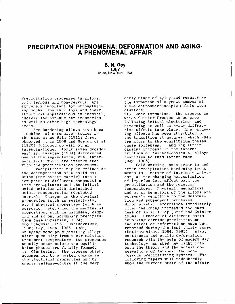
Log 10 time, s
Figure 7- Evolution of the fraction recrystallized with annealing time for the type 430 and 430M
steels.
1.5Temp., 0 C Red., %
0
1 -.5
00
-. 5
-- e .I I
0 1 2 3 4 5Log 10 time, s
Figure 8- Evolution of the fraction recrystallized with annealing time for the type 304 steel.
steels.6
R 3 1/04= log 10 ( 5 31) (2)
A 1040 20
Here, R is the recrystallization rate retardingThe dependence of ts0, the time for 50% of the parameter of the 316 steel in relation to the
material to recrystallize, on the equivalent strain 3 04.steel R3 16 /30 4 is 2.4 at 1000 °C. This is higherin rolling is shown in Figure 9. An expression of than the value of 1.6 calculated from thethe form ts0 i en has been proposed for C-Mn and literature for the same ratio (2).Nb microalloyed steels (11). A thorough review of An activation energy for recrystallization canthese steels (12) has shown that the value of n is be computed if it is assumed that4. In the present investigation, n was found to be1.7 for most of the steels. The type 316, however, Qrex(3displayed n values varying with temperature from txa expi ( - j)4.7 to 2.8 at 900 and 1000 °C, respectively. Here, tx is the time for a given fraction of theAlthough the average (3.7) is close to n -4, values material to recrystallize. In the present paper, tx~reported for the austenitic stainless steels are is equal to t50. Qrex is the activation energy forconsistently lower and approximately 2 (2,3,4). recrystallization, T the absolute annealing
The retarding effects of adding Mo to the steel temperature and R the universal gas constant.can be readily calculated for a given temperature The activation energies obtained were 547, 355from the expression and 120 kJ/mol for the 316, 304 and 430M steels,
23

5_" - I ACKNOWLEDGEMENTS
Logiot50 T.°C % The authors are grateful to Cia Aqos Especiais(s) Itabira, ACESITA for supplying the steels.
o 1040 Thanks are also due to Professor J.J.Jonas and Dr.* 940. x S.Yue of McGill University for their many helpful* 840 comments and continuing encouragement. RB) 1000 '- expresses his thanks to the World University
0 900 Service of Canada for the award of a travelling& 1000 "fellowship and to the UFMG for granting a period
S 900 of sabbatical leave during which this work was10oo carried out. DBS acknowledges with gratitude the
financial support received from FINEP and CNPq2 -during this work.
REFERENCES316. 1- Ahlblom, B. and R. Sandstr6m, Int. Met. Rev.
-- 304 L. 27, 1-27 (1982)
. 430 2- Sandberg, A. and R. Sandstr6m, Mater. Sci.Technol. 2,917-925 (1986)3- Barraclough, D.R. and C.M. Sellars, Met. Sci.
0 - 13,257-267 (1979)0.1 0.5 4- Towle, D.J. and T. Gladman, Met. Sci. 13, 246-
Equivalent Strain 256(1979)5- Richard, P. and T. Sheppard, Mater. Sci.
Figure 9. Dependence of t5o on the equivalent Technol. 2, 841-847 (1986)strain given in the previous pass. 6- Svenson, U.: in "The Hot Deformation of
Austenite", J.B. Ballance, ed. AIME, New York,N.Y., 1977, pp. 499-5167-Keown, S.R.: in "Hot Working and FormingProcesses", C.M. Sellars and G.J. Davies, eds., Therespectively. Qrex values reported in the literature Metals Society, London, U.K., 1980, pp. 140-147
are 525 to 336 kJ/mol for the 316 steel (2,4,13)
and 425 to 334 kJ/mol for the type 304 (2-4,14). No 8- Paxton, M.M. and L. Straalsund, Nucl. Technol.reports were found on activation energy values for 25,546-552(1975)ferritic stainless steels. 9- Andrade, H.L., M.G. Akben and J.J.Jonas,
Metall. Trans. A, 14, 1967-1977 (1983)CONCLUSIONS 10- Cahn, J.W., Ac-a Metall.4, 449-459 (1956)
11- Sellars, C.M. and J.A. Whiteman, Met. Sci.,1- Nucleation in austenitic stainless steels occurs 13, 187-194(1979)mostly at grain and annealing twin boundaries. 12- Sellars, C.M.: in "Hot Working and FormingIntragranular nucleation is also possible in 316 Processes", C.M. Sellars and G.J. Davies, eds., Thetype steel. Metals Society, London, U.K., 1980, pp.1 -15
2- Nucleation in ferritic stainless steels takes 13- Ryan, N.D., H.J. McQueen and J.J. Jonas,place at grain boundaries only. Can. Metall. Q. 22,no 3, 369-378 (1983)3- The kinetics of static recrystallization are 14- Campbell, G.TC., -E.P. Abrahamson Jr. and N.J.slower in type 316 than in 304 steels. This is Grant, Metall. Trans. Aattributed to the presence of Mo in the 316 steel.4- Recrystallization is delayed in 430M steelswhen compared to 430 ones. This is due to theretarding effects of Nb and Ti either in solution oras precipitates.5- Recrystallization follows an Avrami typedependence on annealing time. The values of thetime exponent k in the present research are 0.9,0.8, 1.1 and 0.9 for the 304, 316, 430M and 430steels, respectively. No systematic dependence ofk on either strain or annealing temperature isobserved.6- The dependence of t5 0 on the strain is suitablydescribed by t 50 a p-17 for most of the steelsstudied. The type 316, however, shows a higherstrain exponent of 3.75.5- The calculated values of activation energie forrecrystallization are 547, 355 and 120 kJ/mol forthe 316, 304 and 430M steels, respectively.
24

EFFECT OF PRECIPITATION OF SECONDARY PHASESIN 17-14-2 AUSTENITIC CHROMIUM-NICKEL-
MOLYBDENUM STEELS ON THE EVOLUTION OFLOW-CYCLE FATIGUE CRACKING
Eugeniusz SzpunarInstitute of Atomic Energy,
Poland
Jerzy WawszczakWarsaw University of Technology,
Poland
AUSTEN ITIC CiHROrVIUrM-NICKEL-OLYBDENUM is the diagram /time-temperature-preci-steels, widely used in nuclear power en- pitation/ elaborated for the AISI 316Lgineering as well as in chemical indus- steel by Weisse and Strickler /l/. Ac-try, should be characterized - for the cording to this diagram, the sequencesake of operational safety - by a high of the precipitating phases and the ran-resistance against low-cycle fatigue. ges of their stability can be - for theProcesses of precipitation of intersti- ageing temperature being equal to thattial and intermetallic phases, which ta- of the least durability of the non-equi-ke place in the course of fabrication of librium austenite /800 0C/ - presentedthe installations and equipment, made by means of the following scheme:from these steels, or during their ser-vice, affect their static mechanical X+ M+M23C6+qpropertiesrmerely to a low-degree while _ 'p36 .Cthe influence of these processes on the 0+0.2h 0.2+2.0h 2.0410.0hdynamic oroperties, especially on the hI/low-cycle fatigue resistance, can be of M2C6+ + d M2C6+7+x +essential importance. That is why the 23_6_23_6effect of structural changes in auste- 10.04200.0h >200.Ohnitic steels, taking place during ageingafter quenching, on the development of The kinetics of growth of the indi-cracking under low-cycle fatigue load is vidual interstitial /M2 C / and interme-the subject of investigation in several tallic !3,x,G/ phases as well as theresearch institutions, proportions of these phases permit ma-The investigations so far carried out king the statement that the predominant
focussed mainly on the establishment of p i the pha whe theome
morphology and identification of the proportions of the phases and v mc-precipitated secondary phases while re- rease only when the ageing time exceeds
latively few works were concentrated on r000 h. he hee ing th ec eeds
the cracking process under low-cycle fa- 1000 h. The scheme of the precipitatioCtigue loads. The aim of the present work process in the 00H17N14M2 steel at 815 C,isu ofinds out ainfterreatin p eeen wverified by Bielanik /2/, is as follows:is to find out an interrelation between
structural changes, occurring in auste- M2C r C +26+G +(nitic steels of the 17-14-2 type during 2 3 6+d 423 6ageing, and the evolution of low-cycle O41O.Oh 10.041000.Ohfatigue cracking. 121
STATE OF THE PROBLEM 23 6
PRECIPITATION PROCESSES OCCURRING IN >1000h
THE 0OH17N14V2 STEEL DURING AGEING - Of The 1 phase, occurring at the initialessential importance for determining thedevelopment of precipitation processes stage of the precipitation proceqs, i -of interstitial and intermetallic phases - in the opinion of the authors /3, 4-
25

- the result of a partial decomposition mula /4/:of J ferrite which is present in thissteel in small amounts. According to da/dN = C 6 KM /4/Szpunar and Bielanik /3, 4/, the onsetof the precipitation of the X phase as The instantaneous cracking velocitywell as of the preceding transient pha- as well as the crack trajectory are de-ses, occurs already after ageing times rivative of the process of formation andbelow 10 hours. These phases have a lath displacement of the heavy defected zoneor plate structure, the proneness to surrounding the bottom of the crack un-gliding being therefore restricted in der propagation. The processes of plas-spite of their inconsiderable volume tic deformation taking place in this zo-proportions, not exceeding 3 ? . ne are determinied by such factors as the
level of stacking fault energy and thePHENO-MNA ACCOM-PANYING THE FATIGUE local arrangi.ment of structural consti-
CRACKING - Depending on the magnitude tuents as we .1 as their ahape, propor-and location of the stress amplitude in tion, and properties.the cycle and on the application of pla- The behaviour of aged austeniticin or notched specimens, a different ap- steels during fatigue tests has got noproach is necessary to the interpreta- extensive reflection in the literature.tion of the fatigue of the material, Most of the papers involved refer tosubdivided into an initiation and a pro- phenomena accompanying the fatigue at apagation stage, the research technique maximum cycle stress exceeding the yieldhaving to be adequately modified. The stress or to fatigue taking place atmost manifest result of the fatigue test elevated temperatures, i.e. when an ac-performed on notched specimens at a gi- tive development of the cracks is accom-yen load amplitude, is the number of cy- panied by creep and oxidizing action ofcles which is needed to bring the speci- the environment. In the present work,men to failure /N /. The number of cyc- the findings made by Yamaguchi and Kana-les necessary forc initiating the fractu- zawa /8/ were taken advantage of, refer-re process is generally neglected /IN < ring to the differentiation of the slip10 ! N /. By applying, in the ouantila- band arrangements and of the nature oftive interpretation of the kLietics of fracture in specimens of the SUS 321cracking, the "amplitude of the stress steel aged during various times and atintensity factor" % t, as it has been various temperatures and then subjecteddone by Paris and Erd gan /5/, it is po- to fatigue at elevated temperatures.ssible to perform an analysis of the fa-tigue process at one or - at the most - AIM OF THE WORK- at a few levels of the initial stressamplitude L'5. By following the evolu- The present work aimed at determi-tion of the crack and by expressing it ning the effect of the degree of advan-as a function a = f/N/ /where a is the cement of the precipitation process onlength of the fatigue crack at a known the kinetics of development of fatigueinstantaneous value of the nominal stress cracks and on the fatigue life of theamplitude in the specimen/, one can de- 00H17N14M2 steel aged at various tempe-termine the general form of the equation ratures. One hoped to reveal an effectrepresenting the kinetics of cracking of the precipitation process on the/6, 7/ as structure of slip bands in the neigh-
bourhood of the propagating crack asda/dN = CAn /3/ well as on the topography of fatigue
fractures. In view of the assumption aswhere: to the sensitiveness of this steel withC, n - constants, of the material respect to precipitation processes du-
constant type, ring fatigue cracking, it seemed to beA - function describing any involu- interesting to make a comparison with
tion combination of the ampli- the results of strength tests and har-tude of the stress intensity dness measurements performed for the sa-factor and linearizing the ki- me material in as-quenched condition.netics equation /3/ in the dou- Similarly. taking into considerationble logarithmic coordinate sys- the dislocation model of the plastic de-tem. formation in the crack region, one hoped
The most frequently used measure of the to find a differentiation of the dislo-A iunction is the relation A = A KI, cation structure in the direct neighbour-constituting the classical Parise for- hood of the crack and in the regions si-
tuated far away from the cracking zone.
26

NATERIAL USED FOR INVESTIGATION lowing chemical composition: C - 0.028%,
AND INVESTIGATION PROCEDURE Mn- 1.93%, Si - O.255ACr -17.2%t
Ni - 12.6;, S - 0.011%, P - 0.025%,
The material subjected to investiga- Fe - balance. The specimens were prepared
tion was the 00H17N14M2 steel of the fol- and subjected to examination according toTable 1.
Table 1 Preparation of specimens Investigation programme
1 2 3 4 5 6
Operations:
1. Cutting out2. Roughing3. Heat treatment4. Finishing C
5. Polishing d M6. Etching -
o l.4- F-4 0 l
S0 0 00 ~ Cl) 01 0 0
P -4 -- 0 .4 o¢t '-o %- o o • U0c 0C C'-4 -P 4-)
c 0
77 detail "a" " 0 r
•4 0 .4 *125t ..4 CO o
1 D0 0 0 A 9
4 -0 t
R. o 0 B 0 (o c H.- co Ca -)
001 . 0 +I X ;-9
10 0 10 Z B A
2C 4 H 9 b . -4
0~ .- S 0
00
-Treat- Time Seienubr Number o tested'-mients h Spcmnnmesspecimens
4-)0 1.1 + 1.10 10 10 1 1B 3A 9B
0 0Wno 2 2.1 + 2.10 10 10 1 1B 3A 9B3
$4 00 W 10 3.1 * 3.10 10 10 1 1B 3A 9B
4- WL 0
CO J C\J WD 100 4.1 * 4.10 10 10 1 1B 3A 9B
1000 5.1 4 5.10 10 10 1 lB 3A4 9B3
27

RESULTS OF INVESTIGATION Elongated precipitated particles of thex phase within the grains decorate local-
:ICROSTRUCTURAL EXAI'INATIONS - Vicro- ly, by their shape, the remains of twinstructural examinations served to deter- boundaries and give a distinct indicationmine the degree of changes provoked by that their nucleation took place betweenageing. The polygonal structure of super- the second and tenth hour of the ageingsaturated austenite, containing numerous process /Fig. Ib/.twins, undergoes during ageing /2 h and10 h/ a change manifesting itself by pro- STUDIES ON T F KINETICS OF FATIGUEressive vanishing of twin boundaries CRACKING - Fatigue specimens, of a shapeFig. la/. At the same time, also the de- shown in Table 1, were subjected aftercompcsition of6 ferrite takes place. ageing to a pulsating - from the zeroThis may be seen in Fig. la as elliptic value - bending stress at a constant ma-chains of precipitate at the grain boun- ximum bending force within the cycle gi-daries of austenite. ving in the notch region nominal stres-
a/ b/ ses 6-m = 192 1'a, the frequency being2.5 Hz. an the course of the fatigue test
S.the length of the notch "a" in relation•to the fatigue cracking cycle number I..
. ", was recorded. The test was interruptedand the cracking cycle number "N " was
. - determined after the bend angle Sad rea-,- ched the predetermined value. The expe-
$' * '' rimental cracking curve, written as N =W . = f/a/, was approximated by the quadri-
tic polynomial N = Aa + Ba + C. By cal-culating the inverse of the derivative
Sof the function in the form da/dN=1/2Aa+B/l i !" ' ;': and making a compilation in relation tothe amplitude of the intensity factor 6K,
a serie of pairs of corresponding points,which determine the curve da/dN = f(AK)was obtained. The curve was, next, linea-
Fig. I - Structure of OOH17N14V2 steel rized and such a form of the quantitya/ in as-quenched condition 1250CC/ 2 .5 h was sought which would satisfy the ex-b/ after quenching 1250oc/2.5 h and pression /5/:
egeing 8000C/1000 h.Etched with Villela's reagent. Yagnifi- lg da/dN = nlgXA+ C /5/cation 200x.
In the case under consideration, a sati-An extension of the ageing time up sfactory consistency with the experimen-
to 100 hours markedly increases the et- tal results was obtained by substitutingching intensity of austenite, this being for A the expression /6/:an evidence of an advanced degree of evo- A 2lution of the precinitation process. Si- A Ki) , 6 Ki/n Kimax) /6/milarly, minute precipitate particles I- a.5within some, not numerous, grains can be nK1 4.2 M/(g b) 5 F(a/b) /7/seen.
By supplementary investigations, per- AKimax =-- KI, a = amax /8/formed by electron diffraction technique _3105on extraction replicas, the precipitated F (a/b) = I a/b) (I - a/b .particles involved were identified to bethe X phase. The structure rebuilding In the above-mentioned formulas, g and bphenomena, occurring after 100 hours of are the dimensions of the specimen cross-ageing, intensify as the ageing time is -section, M is the bending moment in theextended until after Polding the steel notch region while a and a represent,for 1000 hours at 800 C they reach a sa- respectively, the instantanus and theturation state while the structure assu- maximum length of the fatigue crack cor-mes a stable form /Fig. Ib/. Especially responding to the critical bend angle.conspicuous is a continuous line of the The correlation coefficient of the equa-precipitated X phase at grain boundaries tion /5/ oscillated around 0.99. By cal-as well as numerous minute particles of culating, for every specimen, the valuesthis phase within the austenite grains. C and n and determining, then, C and n
28

for the given state, a pencil of straight c/lines, as shown in Fig. 2a, was obtained. N 35In view of insignificant differeces inthe value of C for all the specimens in- 30volved, an average _ value was calcula-ted /C = 7.41 x 10 / whereupon, basingon the fixed "C" value, the exponent "n" 25for every state was determined, its va-lue in relation to the ageing time being 0
shown in Fig. 2b. As may be seen from X 20 -
Fig. 2b, the coefficient "n" in the equa-tion of the kinetics of fatigue cracking 15 -has a minimum value at an ageing time of10 hours. Fig. 2c illustrates the effect 10 -iof ageing time of the OOH17N14M2 steel 01 2 10 100 1000 hon the fatigue life expressed by the cra-cking cycles number "N " until the speci-men has been bent thro~gh the predeter- Fig. 2 - Results of fatigue tests:mined angle. a/ averaged results of linearization of
a/ the curves, relating to the kinetics of
do 6 fatigue cracking, by means of the func-tion 5, where: 1 - after quenching,
dg 5 5 2 - after ageing for 2 hours, 3 - afterageing for 10 hours, 4 - after ageingfor 100 hours, 5 - after ageing for
4 1000 hours;4 b/ Variation of the exponent 'n" of the
curves of fatigue cracking versus ageingtime;
c/ variation of the fatigue life "N "
versus ageing time. c
2 RESULTS OF INVESTIGATION OF SLIPBANDS DENSITY IN THE PLASTICALLY DEFOR-MED BOTTOM OF THE FATIGUE NOTCH - On thebasis of microstructural examination an
2 attempt was made to assess the density1of slip bands within the grains in the
immediate neighbourhood of the fatigueL I I i crack. The results of microscopic exami-1,2 1,5 1,8 2.0 2,5 3,0 igA nation of the region adjoining directly
the crack are shown, for the as-quenchedb/ condition as well as after ageing for
100 hours, in Fig. 3. By calculating -- for a given number of cracking cycles-the ratio of the number of grains contai-ning slip bands to the control number ofgrains in the region of the bottom of the
2,0 fatigue crack, a scheme of the increasein density of slip bands with increasingnumber of cracking cycles was obtained,as shown - for all structural states ofthe material - in Fig. 4.
1,5 As may be seen, a complete malleab-lizing of the control number of grainsin the region of the bottom of the fa-tigue notch is likely to appear ageingfor not more than 10 hours.
1,0 -As could be expected, a very distinctdecrease in density of slip bands with
I I the extension of ageing time and inten-0,01 2 10 100 1000 h sification of the precipitation process
has exerted an effect on the dislocation
29

density in the region of the fatiguenotch. Dislocation density not only de- W 1,0 1 2 3 / -*pends on the conditions of fatigue cra-cking but is nizo a f.znction of the dis- Up , 4tance from the bottom of the fatiguecrack under propagation. 0.6
a/ b
0,2
1,5 3,0 4,5 6,0 7,5 9,0 10,5 12,0103 cycies
Fig. 4 - Change in density of slip bands. ... in the fatigue notch region, expressed
- 1 as the ratio of the number of grains inwhich slip occurs to the control numberof grains "W" versus number of fatigue... cracking cycles., - in as-quenched condition, 2 - afterageing for 2 h, 3 - after ageing for
10 h, 4 - after ageing for 100 h,
5 - after ageing for 1000 h.
c/ d/ Specimens for transmission electron mi-
croscopy examinations were prepared bycutting out thin slices /0.1 mm/ and by
.. > electrolytic thinning, until reaching a, foil thickness, parallel to the fatigue
crack surface, at a distance of 0.2,purposes such a specimen was chosen from
-.. a given state which turned out to beclosest, according to Fig. 2c, to theaverage value characteristic of the gi-yen stete. A foil segment permits, depe-
'- ' nding on the perforation site, an appro-ximate establishment of the number ofcracking cycles, determining the pattern
' of the dislocation structure. For inves-tigation, only regions having an identi-
V : V \ cal orientation with respect to the axesof the zone: /110/ and /111/ were selec-ted. A contrast juxtaposition of the pat-
P'ig. 3 - .'icrostructure in the region terns of distribution of dislocationsof the fatigue notch bottom after va- and slip bands testify to the existencerious cracking cycles number: of an essential interrelation betweena/ in as-quenched condition, 500 crac- the intensity of the precipitation pro-king cycles; cess and the dislocation structure.b/ in as-quenched condition, 8000crac- After ageing for 100 hours, dislocationking cycles; tangles are replaced by single disloca-c/ after ageing for 100 h, 500 cracking tion loops or not numerous dislocationcycles; lines concentrated in the boundary re-d/ after ageing for 100 h, 8000cracking gion. Numerous slip bands, occurring incycles; as-auenched condition /Fig. 5a/, under-Specimen etched with Villela's reagent go an essential reduction as the distan-prior to fatigue testing. Magnification ce from the fracture surface is growing,150 x. or begin to vanish completely after age-
ing for 10 hours.
30

a/ b/ ' _RSULTS OF FRACTOGRAiHIC ExAVII:ATICO:-From among the many morpholog'ic formsof fatigue fractures such ones, six innumber, weie chosen which corresponddistinctly with the course of fati-iiephenomena at various stares of the pre-cipitation process. The successive pic-tures /Fig. 6/ represent the evolutionof cracking from the as-quenched condi-gn, tion to that after ageing for 100 hours.
C/ d/"
Fig. 6 - Passage of fatigue crack thro-ugh twin boundary. Fatigue fracture ofa specimen in as-quenched condition.±7agnification 330 x. Fracture surfaceetched.
7ig. 5 - Arrangement of dislocationsand slip bands in as-quenched conditionand after ageing for 100 hours: ft -a/ reyion in the immediate neighbour-hood of the crack, as-auenched condi-tion, cracking cycles number 800 - 15 000magrnification 7 000 x;b/re ion at a distance of 4.5 mm fromthe crack, cracking cycles number 8 000 Fig. 7 - Licrocracks in terrace arran-- 15 000, manification 16 000 x; gement. Fatigue fracture of a specimenc/ re-ion in the immediate nei,7hbour- after ageing for 100 h. Niagnificationhood of the crack, after ageing for 100 7 000 x. Fracture surface etched.h, cracking cycles number 2 000 - 4 000,ma-nification 12 000 x; The topography of the fractures isd/ region at a distance of 4.5 mm from constituted by developed systems of jogsthe crack, cracking cycles number of differentiated sizes and development3 000 - 15 00i, manification 10 o0 x. directions. The lack of the phenomenon
of plastic "crack closing" in the com-pression half-cycle /in view of a pul-sating - from the zero value - courseof the load cycle/ has caused in manyregions a decay of the typical set offatiFue striae. In other regions, a
31

network of microcracks, up to 5 um long, from an intercrystalline to a transcrys-situated at the intersection of slip pla- talline one. This process concerned thenes with the cracking surface, was reve- particles of the phase precipitated wit-aled. The successive pictures /Fig. 8 hin the grains /Fig. 10/ while in theand 9/ represent the image of the aus- boundary region the precipitated parti-tenite grain boundary decorated with pre- cles underwent decohesion along graincipitated particles of the X phase. In boundaries as shown in Fig. 11.spite of a considerably higher magnifi-cation , the precipitated particles in-volved are after ageing for 100 h mar-kedly smaller than those observable af-ter ageing for 1000 h /Fig. 8/.
Fig. 10 - Region with cleavage cracking• of the phase within austenite grains.Fatigue fracture of a specimen aged for
Jw" 1000 h. M1agnification 5 000 x. Fracture7ig. 8 - recipitation at austenite gra- surface etched.in boundary. 'atigue fracture of a spe-cimen after ageing for 100 h. M'agnifi-cation } 600 x. Fracture surface etched.
- Fig. 11 - Region of the austenite grainboundary decorated with precipitated
7ig. 9 - Precipitation at austenite gra- particles of the X phase. Fatigue frac-in boundary. Fatigue fracture of a spe- ture of a specimen after ageing forcimen after ageing for 1000 h. 1agnifi- 1000 h. Magnification 3 500 x. Fracturecation 2 600 x. Fracture surface etched, surface etched.
A developing fatigue crack, coming RESULTS OF MECHANICAL TESTING - Theacross minute Drecipitated particles of changes observed in the course of fati-the X phase /characteristic for short gue testing of the specimens aged forageing times/, generally passed round various times required a corroborationthese obstacles, thus increasing the or some commentary ensuing from the in-amount of energy consumed for fracturing vestigation of other strength proper-the specimen. The growth of the t phase ties and from hardness measurements.particles to the sizes shown in Figs 10 In Fig. 12, the variation of fati-and 11 has ualitatively changed the me- gue properties, expressed by "N " andchani m of cracking of these particles "n", as well as of such mechanigal
32

1,2TENSILE STRENGHT Rm
-HARDNESS HVl
1,0 NcRm .-: ' -- . . . ." . - -'-. ,.."'Z ... ... ._ ,._ . .-- -
Ni cCI -X.-.... . . . . . . .. . ." YIELD STREN T R 02
0,9 [._ R.Q, \ \" I I-R C PARAMETER nr . '-•.
0,87 ~iV -,.." ELONGATION AT FRACTURE A 5 5 -.,.
A---5- FATIGUE LIFE Nc ,0,6 A _ ____-
n0,5
0,01 2 10 100 1000 h
Fig. 12 - Effect of ageing time on selected mechanical properties of0CH1714F2 steel
properties as tensile strength /Rm/, of- ing process, was very weakly accentuatedfset yield stress /R 2/ , percent elon- and had only an inconsiderable effect ongation after fracture /A5/ and Vickers static mechanical properties and on thehardness /HV/ has been presented as a fatigue cracking process. In the steelfunction of ageing time. In order to under investigation, an essential inf-perform a simultaneous assessement of luence on the properties was exerted bythe sensitiveness of the individual pa- the processes of nucleation, growth andrameters to the precipitation process, coagulation of the intermetallic ^ phase.all the results of investigation have In view of a low proportion of high-tern-been represented in fraction form, in perature & ferrite, its decompositionrelation to the as-nuenched condition products did not show any remarkable ef-assumed as a reference state. fect on the mechanical properties.
As already suggested earlier, fati- Taking into consideration the mate-gue properties /particularly the fati- rial and the conditions of experimentalgue life "Nc"/ show, along with the elo- procedure, the statement can be madengation A5, the highest sensitiveness that of a decisive importance, from theto changes in intensity of the precipi- view-point of the fatigue life and thetation process. kinetics of fatigue cracking, is the pro-
portion and morphology of the ^ phase.DISCUSSION OF THE RESULTS The processes of nucleation, growth and
coagulation of the X phase are in theThe fragments of an extensive inves- most unambiguous way described by the
tigation programme, presented in this duration of ageing after quenching. Thatpaper, have fully corroborated the the- is why, in the following discussion, thesis on the effect of the precipitation ageing time has been adopted as the ba-of interstitial and intermetallic pha- sic factor for performing the analysis.ses in the 17-14-2 chromium-nickel-mo- The dependence of the fatigue lifelybdenum steel on the -volution of low- on the ageing time can be subdivided in--cycle fatigue cracking and on the low- to three stages. The first stage of the-cycle fatigue life. The processes of initial period of ageing extends from 0precipitation of interstitial and inter- to 2 hours. Hfere, as a result of diffu-metallic phases, taking place in this sion processes, precipitation of a smallsteel, have a different meaning for the amount of carbides of the 1'2 C6 type ta-course of fatigue cracking. In view of kes place while the process df nuclea-a very low percentage of carbon in the tion of the %4 phase has not begun as yet;steel under investigation, the process one can assume that it is only in theof precipitation - mainly of the 1',.C 6 incubation period. A decrease in hard-type carbides - which normally tak ness and in offset yield stress, and anplace at the initial stages of the age- increase in ductility, expressed by
33

percent elongation, occurs. These proce- to the interference of the traces of pas-sses and the resulting changes in static sage of the crack through the slip sys-properties entail a considereble shorte- tem with fatigue atriae.ning of the fatigue life. At the sametime, they influence favourably the ki- REFERENCESnetics of cracking which is characteri-zed by a decrease of the exponent "n" 1. B. Weiss, R. Strickler, Metallurg ,
in the equation of the kinetics of fa- 851 /1972/tigue cracking. A characteristic featu- 2. J. Bielanik, Doctor's thesis, Silesianre of this structural state is an int- University of Technology, Gliwiceracrystalline cracking of austenite gra- /1987/ins. 3. E. Szpunar, J. Bielanik, Report on
The second stage extends over the the research work entitled "Investi-ageing time from 10 to 100 hours. In gation of the processes of precipita-this period, marked changes occur in tion of intermetallic phases in thethe structure, consisting in nuclea- 0OH17N14M2 steel", Warsaw Universitytion and growth of numerous particles of Technology, Plock /1985/of the X phase, mainly in the regions 4. E. Szpunar, J. Bielanik, 4th Interna-of austenite grains and twin boundaries tional Congress on Heat Treatment ofas well as within austenite grains. Materials, West Berlin /1985/Apart from that, decomposition of hbgh- 5. P. Paris, P. Erdogan, Journal of Ba--temperature d' ferrite into the E phase sic Engineering Trans., ASME /1963/and austenite takes place. Tensile 6. J. Viawszczak, Doctor's thesis, Insti-strength and hardness show an increase, tute of Materials Science, Warsawoffset yield stress becomes stabilized University of Technology /1981/while percentage elongation decreases. 7. J. Wawszczak, Mechanics 104, WarsawA decrease in density of slip bands in University of Technology-77987/the re~ion of the notch bottom is obser- 8. K. Yamaguchi, K. Kanazawa, Transac-vable. In this range of precipitation tions of National Research instituteprocesses, the fatigue life does not for Metals, vol. 25, /1983/show any significant changes while the 9. K. Hatanaka, H. Kanabe, T. Yamada,
exvonent in the enuation of the kine- The Society of Materials Science,tics of fatigue cracking increases. Japan Kyoto /1972/Fracture topography indicates that cra- 10.W. T. Troshchenko, "Cyklicheskaya de-cking goes through the precipitated par- formacya i ustalost metallov", Nau-ticles of intermetallic phases. kova Dumka, Kiev /1985/
The third stage covers the ageing 11.M. Siratori, T. Miesi, H. Maisita,period in the range from 100 to 1000 "Vychislitelnaya mekhanika razrushe-hours. A decrease in formation of new niya", Izdatelstvo "Nir", transl.nuclei of the 'X phase is observed while from Japanese /1986/the already existent precipitated par-ticles growi and coagulate. Hardness andoffset yield stress do not vary to anappreciable extent while the percenta-ge elongation shows a decrease. In theregion of the notch bottom, the densityof slip bands distinctly decreases. Thefatigue life becomes shorter while theexponent "n" in the eriuation of fatiguecracking increases. An analysis of thetopography of fractures indicates thatthe ratio of the intercrystalline to theintracrystalline fracture increases.
The present work has demonstratedthat even minor amounts of intermetallicphases, precipitating in the ageing pro-cess, are likely to exert an essentialinfluence on the low-cycle fatigue lifeas well as on the kinetics of fatiguecracking. The topography of fracturesdepends on the morphology of the preci-pitated secondary phases and on the de-gree of advancement of the precipita-tion process. Fatigue fractures testify
34

AGING BEHAVIOR OF DOUBLE QUENCHED AND COLDWORKED MULTIPHASE STAINLESS STEELS
F. D. S. Marquis, S. F. Wang, J. H. Qadri, M. Hadji, M. N. DatarDepartment of Metallurgical Engineering
South Dakota School of Mines and TechnologyRapid City, South Dakota 57701, USA
ABSTRACT steels as the main candidates for first wallmaterials in fusion reactors. Two major types of
An investigation of athermal, stress stainless steels are commercially available,assisted, strain induced and isothermal phase single phase (austenitic, ferritic andtransformations and phase transformation martensitic) and duplex (austenite/ferrite andstrengthening has been carried out on three low ferrite/martensite). Only in the last decade,carbon, low nitrogen and low phosphorus many millions of dollars have been spent world-multiphase stainless steels of the types: Fe- wide in an attempt to maximize simultaneouslyCr-Ni-Ti; Fe-Cr-Ni-Ti-Nb and Fe-Cr-Ni-Ti-Mo. The the strength, toughness, formability andcombination of Ti, Nb, Mo and P; low C and N pitting/crevice corrosion resistance ofcontents with very high density of athermal and stainless steels. This is justified by thedeformation induced transformation products; complexity of these steels, where various phaseshigh density of substructure (dislocation, twins and morphologies can be obtained, some of themand stacking faults) increased the nucleation being deleterious such as the sigma ( o ) and therate of MC carbides and delayed the Laves phases (1,2). This transfers to theheterogeneous precipitation of M23C6 carbides at materials scientist a heavy responsibility totriple points and grain boundaries. The final insure that these alloys are properly designedmicrostructures consisted of the intertwinning and successfully employed.phases: athermal, stress assisted and strain The microstructural design and theinduced martensites, TiC, NbC, MoC and prediction of the evolution of thephosphides. Tensile strengths in excess of 180 microstructure under load, at elevatedKsi were obtained at 293 K. These strength temperatures and under irradiation, islevels were maintained without any significant surrounded by tremendous complexity and thusdecrease up to 573 K. The Cr-Ni-Ti-Nb multiphase very difficult to achieve. In addition to thesteel exhibited the best combination of preirradiation microstructural variables, theductility and resistance to dislocation motion designer needs to consider stress, temperature,in the temperature range 293 K to 773 K. irradiation nature, dose, dose rate and He/dpaHowever, in the temperature range 773 K to 973 K ratio. Most of the data now available concerningthe best combination of these properties was these variables has been obtained on austeniticexhibited by the Cr-Ni-Ti-Mo multiphase steel, stainless steels, both metastable such as 304The elevated temperature strength and stable such as 316 and PCA (3 to 7).characteristics of these multiphase dispersions In order that these stainless steels can besuggest that these steels may have a much better successfully employed as first wall materials infatigue-creep behavior under in situ irradiation fusion reactors, various major problems must beconditions than any commercial material solved first: loss of ductility, sensitization,currently available. void swelling and helium embrittlement during
elevated temperature irradiation (6 to 9). Basedon the major problems encountered, attemptshave been made recently to modify and improve
THE MECHANICAL PROPERTIES and corrosion these steels (10 to 15).resistance of stainless steels have justified The objective of this research program, oftheir incorporation in nuclear reactors, which partial results are reported in this paperchemical reactors, superheaters, boilers and in and elsewhere in this congress, (15) is to solvethe construction industry. Currently a large totally or partially some or all of the problemsamount of attention is being given to these reported above.
35

cycle of deformation and aging is designated by
SID the first digit, 1, and the second cycle by thefirst digit, 2. The meaning of the second digitsare: 0 - solution treatment, 1 - waterquenching, 2 w liquid nitrogen quenching, 3 -deformation at 293 K up to 1.6 true plastic
S11 11A strain, 4 = deformation at 77 K up to 1.6 trueplastic strain. Capital letters mean aging at
Table 1- Compositions of Precipitation HardenedS12 S12A Cold Worked Multiphase Stainless SteelsLNQ T-773K
MPSSCr-Ni-Ti Cr-Ni-Ti-Nb Cr-Ni-Ti-Mo
Comp.
c7 Ic.293K1 Type 6 C 0.046 0.047 0.0461 7 N 0.024 0.024 0.025
S14E 540 S414C SI48 S14A fl 7- Type 24 Cr 16.00 16.03 15.913973K T873K T 773K 2 28 Ni 11.95 13.64 16.17
Type 22 Ti 0.18 0.17 0.173 41 Nb 0.006 0.79 0.024
142 Mo 0.005 0.005 0.83
14 Si 0.75 0.74 0.72Type 15 P 0.023 0.025 0.0194 16 S 0.022 0.021 0.020
524 ST - SOLUTION TREATMENT 25 Mn 0.97 0.97 0.98C.77K WO - WATER QUENCHING
LN - LIQUID NITROGEN QUENCHING Calc. Cr 17.13 17.54 17.83C. * DEFORMATION AT Eqt.
!24A T - AGING TEMPERATURE Calc. Ni 13.82 15.54 18.04Eqt.
Fig.1 Flow diagram of the sequences oftransformation, deformation and aging the following temperatures: A - 773 K, B - 873processing K, C = 973 K, D = 1073 K, E 1173 K. All the
aging processes were carried out for a timeThe specific project goals are to design, period up to 1000 hours. Small letters mean: h -
manufacture and evaluate multiphase stainless hours; m - minutes.steels (MPSS) consisting of complex mixtures of The microstructures were characterized byaustenite ( Y), athermal martensite ( a 'A), optical microscopy, scanning electron microscopystress assisted and strain induced martensites (SEM), conventional transmission electron
E 'D9 a'D); very fine dispersions of microscopy (CTEM), and scanning transmissionintragranular carbides of the MC type: TiC, NbC analytical electron microscopy (STAEM), (17). X-and MoC and very fine dispersions of Fe-Ti ray diffractometry, selected area diffractionphosphides. The long range evaluation program (SAD), microdiffraction (MD) and magneticinvolves creep, creep-fatigue and irradiation measurements were used to identify, characterizecreep-fatigue tests. and measure the amounts of the phases formed
during each process of deformation and aging.EXPERIMENTAL PROCEDURE Precipitate extraction methods were applied on
grip portions of the tensile specimens whichThe compositions of the multiphase steels were immersed in a 10% solution of bromide in
used in this investigation are presented in methanol, initially for 24 hours.The residuesTable 1. Figure 1 shows a flow diagram of the were then collected and prepared for X-raysequences of deformation and aging processing diffraction analysis. Mechanical properties werecarried out in order to achieve the desired measured using a Vickers diamond pyramidmicrostructural design. Table 2 defines the hardness tester, a Knoop microhardness indenterprecise nature of each process of deformation and a MTS mechanical testing machine. The yieldand aging. In the interpretation of this table strength a , the tensile strength Out and theand of the nomenclature presented in this paper, elongation at'fracture % El, were measured inthe following code must be used: the first the temperature range, 293 K to 973 K, and in
36

the strain rate range, 10-5 to 10-3 sec-i. 16 wt%. The manganese and the silicon contentswere kept at approximately 0.97 and 0.74 wt%,
Table 2.- Deformation and Aging Processing respectively, to insure deoxidation. The ratioMn/Si was kept at above one in order to insure
Proc. good fracture toughness. Strong carbideNo. Nature of Process formers: Ti, Nb and Mo were added at
approximately 0.18 wt% Ti, 0.80 wt% Nb and 0.80First Cycle of Deformation and Aging wt% Mo in order to be able to produce a very
fine dispersion of intragranular MC carbides.S1O Solution treatment. The formation of these carbides raised the M.S1 Water quenching following S10. temperature and allowed the production ofS12 Liquid nitrogen requenching following secondary hardening upon quenching to liquid
SIlI. nitrogen.S13 Deformation by rolling at room Although C and P have been reported with the
temperature (293 K) following S12. capacity of retarding the formation of LavesS14 Deformation by rolling at 77 K phases at grain boundaries (14), their contents
following S13. were kept here deliberately very low atapproximately 0.046 and 0.024, respectively.
S1IA Aging at 773 K of SI1. This was in order to retard the formation ofS12A Aging at 773 K of S12. M23C6 carbides at triple points and grainS13A Aging at 773 K of S13 followed by boundaries. However, the phosphorus content was
water quenching (WQ). kept at 0.024 in order to induce the formationS14A Aging at 773 K of S14 followed by WQ. of phosphides (Fe-Ti-P) and to balance the ratioS14B Aging at 873 K of S14 followed by WQ. of the MC/phosphide phases. Both phases wereS14C Aging at 973 K of S14 followed by WQ. designed to refine the helium bubbleS14D Aging at 1073 K of S14 followed by WQ. distribution and improve void swellingS14E Aging at 1173 K of S14 followed by WQ. resistance. In addition, the formation of a veryS14AA Aging at 773 K of S14A followed by WQ. fine dispersion of intragranular MC carbides
appeared to have the capability of trappingSecond Cycle of Deformation and Aging helium bubbles at their interfaces, preventing
the coarsening of these bubbles at the Y/y grainS22 Liquid nitrogen quenching following boundaries which provides resistance to helium
SI4A. embrittlement. In the microstructural design,S24 Deformation by rolling at 77 K additional intragranular trapping for small
following S22. helium bubbles was provided by very fineS24R Deformation by rolling at 77 K dispersions of tempered athermal, stress
following recrystallization during assisted and strain induced martensites.S14C, S14D or Sl4E. The chromium and nickel contents were
$24A Aging at 773 K of S24 followed by WQ. adjusted in order that the martensite starttemperature (M.) was between room temperature(293 K) and liquid nitrogen temperature (77 K)and the martensite finish temperature (Mf) was
RESULTS AND DISCUSSION below 77 K. In these steels most of theaustenite (y) was retained upon water or brine
Both theoretical and experimental results quenching. These alloys were then partiallywhich are part of those obtained in this transformed to athermal martensite ( a'A) byresearch program are presented and discussed requenching in liquid nitrogen and held at 77 Kbelow: to achieve temperature homogenization and full
transformation as shown in Figure 2 and table 3.DESIGN OF MULTIPHASE STAINLESS STEELS These microstructures (consisting of a mixture
of austenite and martensite) were then deformedThe design of these multiphase stainless by rolling (ausmarforming) up to 1.6 true
steels is primarily a two fold design: the cumulative plastic strain at 293 K and 77 K.chemical design and the microstructural design, This resulted in the transformation of thein order to achieve an optimized combination of metastable austenite into a very large volumephysical and mechanical properties, fraction of martensites ( e'D, E'D) as shown in
The chemical composition of these multiphase Figures 3 to 6 and table 3. The two major rolesstainless steels was adjusted by manipulating of the athermal martensite were first to providethe content of four major types of elements: nucleation sites for the formation of stresscarbon and nitrogen in the first; chromium and assisted and deformation induced martensite,nickel in the second; titanium, niobium and and, secondly, together with the latter refinemolybdenum in the third, and silicon and the helium bubble distribution by providingmanganese in the fourth. In order to obtain the interfaces capable of trapping fine heliumformation of a passive oxide film and insure an bubbles. These microstructures (consisting of aeffective corrosion and oxidation resistance, mixture of austenite and martensite) were thenthe chromium content was kept at approximately prevented to reverse directly into austenite and
37

- 4A-A Z
54ii 54 vtm 54 U'm
- -
54M54i' I
9 01
4 Pm5-.m5 3
- - - MO
Fi. Wae n *iudntoe unhn epne of MS:a of eC-iT;a eand i
Sl b) tf:mrhlg of aAi S1;g an h) eC-iT-b mopooyO Aan ' in 12
ig2Wtr ndlqi nirgnqecigrsoe ofPS a) tf) Fe-Cr-Ni-Ti; a retained in
38

0 o stabilization of the martensite interfaces anda raising of the Ms temperature due to theo depletion of the austenite lattice of
450 stabilizing solutes. Since the aging temperature0
was 773 K, the precipitation processes involve0 not only the diffusion of interstitial solutes
400 - of type 1 (carbon and nitrogen) but also400 /- substitutional solutes of type 3 (Ti, Nb and Mo)
0 *."
- and type 2 (Cr). No significant diffusion of350 substitutional solutes of type 4 (Mn and Si) was
0 *i observed. This is explained by the lower/ stability (i.e. less negative energy of
300 formation of their carbides and nitrites). As a/ ST:1428K, 0.5hr consequence of the additive application ofausmaraging (or amaraging for short) to a
25/" WQ4-77-K WQ/LNQ/F-77*K WQ/e-293"K microstructure obtained by ausmarforming (or250 / amarforming for short), the nucleation rate
o Fe-Cr-Ni-Ti • obtained for very stable MC types of carbides,2 Fe-Cr-Ni-Ti-Nb U dN/dt = N, was very large, much larger than the
20 Fe-Cr-Ni-Ti-Mo density of heterogeneous nucleation sitessupplied by triple points and grain boundaries.This resulted in a very fine dispersion of
150 intragranular carbides which raised theA i recyrstallization temperatures of these
0.5 1.0 1.6 microstructures to very high values, typicallyTRUE PLASTIC STRAIN 1173 K as shown in Figures 7 through 13. In
order to achieve further multiple refinement of500 bthe microstructure ( y' , 'A' -' D, ct'D these
microstructures were then requenched in liquidnitrogen directly after precipitation hardeningor after prior recyrstallization, reapplied toadditional cycles of deformation and aging as
400 0 shown in Table 2. Upon the application of only400two full cycles of amarforming and amaraging,
very fine multiphase microstructures were
obtained with a typical grain size between 1 Pmand 5 im. These microstructural refinementscombined with thermally stable multiphasestructures, with phases of considerably
/3 different chemical compositions, resulted in a
0 very attractive combination of resistance
S 1506K, 0.5hr/WQ/LNQ todislocation motion, crack propagation andT 7corrosion resistance, in the temperature rangect 77K 293K 293 K to 773 K.
200 Cr- Ni- Ti 0 0Cr- Ni- Ti- Nb a 0Cr- Ni- Ti- Mo A 4 QUENCHING RESPONSE
The quencing response of the Cr-Ni-Ti, Cr-Ni-Ti-Nb and Cr-Ni-Ti-Mo steels is shown in
figure 2. A small but significant increase in0.5 1.0 1.5 the water quenched hardness (typically DPH=122TRUE PLASTIC STRAIN to DPH=133) was observed with increasing
solution treatment temperature 1373 K to 1506 K,Fig.3 Effect of solution treatment temperature, in all steels. This hardness increment isamount of plastic strain and deformation explained mainly by the higher solute content oftemperature on the deformation behavior of MPSS the austenite at higher solution treatment
temperatures. Upon requenching in liquidor recrystallize by heating very slowly nitrogen a considerable increase in hardness(ausmaraRing) at 773 K. This resulted in (typically above DPH=20) was observed for alldiffusion controlled transformations, involving steels. This increment in the hardness isnucleation and growth during which very fine explained by the formation of athermalintragranular dispersions of the most stable martensite with morphologies typically shown inalloy carbides, of the MC type: TiC, NbC and figure 2. This requench hardening increased withMoC (by decreasing order of stability) were increasing volume fraction of athermalformed. During tempering three significant martensite formed, which increased as theprocesses occured: precipitation hardening, calculated Ms increased. These Ms temperatures
39

ot~a b
11 49
V. -- 0
Ir - 4 -I\
A 4
54 un S4-:IPA~
W Ig
6- -v
Fig.4 Formnation of stress assisted and strain induced martensite in Cr-Ni-Ti MPSS by S13 and S14: a)
and h): ;=-0.2, 293 K; showing IA and"D'r; c) c-0.5, 293 K; d) E-0.29, 293 K, e) c-1.6, 293 K
showing cellular structures; E) cs,0.2, 77 K, g) f-=0.5, 77 K. h) c =1.6, 77 K, i) c =-0.2, 77 K
40

- I
'/N
'44

p -T - - ~ t j,
4I 5
'led
2. ...-
OM 10 -palZ
I'" 1 i I=4"
Fig.6 Formation of stress assisted and strain induced martensites in Cr-Ni-Ti-Ho MPSS by S13 and S14:
a) .=0.2, -,Q-A K, h) ,-.,291 V, r) -0.9, 201 K, d) -=1.6, 293 K, e) v=0.2, 77 K, f) r=0.2, 77 K, g)
=0.2, 77 K, h) .-=0.5, 77 K, i) _=0.9, 77 K. Notice _'D substructure in f) to i)
42
600 a-d70 ' Cr- Ni- Ti True Plastic Strain6 .2 .5 .9 1.62CWV/c.293K/773K Q
1600 WQ/LNQ/c.77K/773K
500 __ _ _-
Cr- Ni- Ti 0 0 400_
773 K Aging Time. 1 10 100
300I I1
0.25 0.50 0.75 __
TRUE PLASTIC STRAIN AT 77 K_ _ _-_-
10 100Cr- Ni- Ti- Nb 0 [ A TIME, HOURSAging Time Hrs. 1 10 100
700 At 773 K e700 ----
00600
0; ,- I Ti- Nb
0 4True Plastic Strain40. .5 .9 1.6a00
WO/, .77K/773K O v 0-0.
WO/LNQ/,77K/773K 0 Y+
1 10 100TIME, HOURS
400
5000.5 1.0 1.5
TRUE PLASTIC STRAIN AT 77 Ky
400S600 C
'A 300
Cr- NI- Ti- Mo True Plastic Strain500 .0 .2 .5 .9 1.6WQt.77K/773K 0 -'V "
WQ/LNQ/c.77KI773K * *+
400 10 100
TIME. HOURS
Cr- Ni- Ti- No 0 0 6773 K Aging Time Mrs. 1 10 100 Fig.7 First cycle of aging of cold worked MPSS
showing the effect of amount of deformation ,L L deformation temperature, aging temperature and
0.5 1.0 1.5 aging time on the hardness: a) to c) STr- 1506TRUE PLASTIC STRAIN AT 77 K K, d) to f) STr- 1428 K
43

were estimated to be 238 K, 188 K and 138 K for aCr- Ni-Ti 0 A 0 0
Cr-Ni-Ti, Cr-Ni-Ti-Nb and Cr-Ni-Ti-Mo steels a 72 at- 0.2 0.5 0.9 1.6respectively.
AGING OF QUENCHED SPECIMENS 600 0
The aging of quenched specimens, both water s00quenched and liquid nitrogen requenched showed I ,-O o _ _little hardness increment during aging at 773 K.-- ----o -This is explained by the heterogenous 400
precipitition at triple pointq and interfaces.1 10 100 1000FIRST DEFORMATION CYCLE TIME, HOURS
The first deformation cycle (S13 and S14) 700 flshowed considerable increase in the resistanceto dislocation motion, as shown in figure 3. 600 0_ ________
This deformation behavior is significantlyinfluenced by the solution treatment 50temperature. The effect of the amount of5o
deformation and deformation temperature on themicrostructure is shown in figures 4, 5 and 6, 400 Cr-Ni- Ti- Nb 0for Cr-Ni-Ti, Cr-Ni-Ti-Nb and Cr-Ni-Ti-Mo steels 0/o 773KAoing
True plastic strain 1.6 0.9 0.5 0.2respectively. For the same amount of plastic -strain, larger amounts of deformation induced 1 10 100 1000
martensites ( E'D, a'D), larger increases in TIME, HOURS
DPH, ay and au and larger decreases in 60
ductility were observed at lower temperature (77 6
K) in all steels. This is explained by anincrease in the negative volume free energy AGv 500 _-_---___
and a decrease in the total free energy AGT forLhe formation of martensite with the consequent 400
decrease in the critical size of the embryos, 0 --
and the correspondent increase in the nucleation Cr- Ni- Ti-Morate N at lower deformation temperatures. This 300 77 K Et z 0.2 0.5 0.9 1.6
is in agreement with the classic theories ofmartensite nucleation as reported by Marquis 1 10 10 1000
T"', HOURS
Table 3.- Combined Results of X-Ray Diffractionand Magnetic Susceptibility Analysis Fig.8 Aging behavior of MPSS solution treated at
STEEL Cr-Ni-Ti Cr-Ni-Ti-Nb Cr-Ni-Ti-Mo 1506 K
X-ray Magne X-ray Magne X-ray MagneTMT -tic -tic -tic
Diff. Susc. Diff. Susc. Diff. Susc.
WQ y WM y NM y NM7 00 -A
WQ+LNQ Y "A WM Y aA WM y NM
KM 00.2 Y, A aD SM YnA,AaDSM Y ,nA ,DI 600
E t' 0.5 SM SM SM
77 K 0.9 SM SM ,, SM SO Cr- 1n- T1-Solution Treatment0.2 SM SM "MM Temratue- IS k 1420K 138K
TT - Thermomechanical Treatment; Et - true 10plastic strain; NM - non magnetic; WM = weakly TIME. HOURS
magnetic; MM - mildly magnetic; SM - stronglymagnetic. Fig.9 Effect of prior solution treatment(11,16) and Marquis and Thadhani (10) and temperature on the aging behavior of Cr-Ni-Ti-NbMarquis and Fejokwu (12,13). MPSS
44

sOS v* -
* :457;
V. ''"N
~( -~'. - 4
C. r
St £f
At
"('A
- S.-.-"-ar

Cr- NI- TI773k, first aging, 1hT
550
V) 540
0:
530
$2o L10 11M520
510 I11010
TIME, HOURS SECOND AGING )
Soo Cr- 14i- Tib773K. first aging, 12hra 4
490L
10 vim
480
Fig.ll Second cycle of deformation aging:precipitation hardening, a) to c); fine and
470 uniform dispersions of MC carbides in d) Cr-Ni-
Ti and e) Cr-Ni-Ti-Mo
460 specimens did not exhibit much secondaryhardening. This is explained by the fact that
_ ____the Ma temperature was not raised significantly10 100 above 293 K by carbide and phosphide
TIME. HOURS SECOND AGING) precipitation during the first cycle of aging.
Thus the double aging followed by waterquenching showed little hardening as expected.However the specimens that have been quenched in
liquid nitrogen showed significant secondary
773K, first aging, 1tC hardening, which was explained by the second
It-0.9 formation of athermal martensite, which was540 -0 possible due to the significant raising of the
M. above 77 K during first cycle of aging. Thesemicrostructures, with the second generation of
5athermal martensite exhibit slightly better, butnot very strong aging response.
SECOND CYCLE OF DEFORMATION AND AGING
520 The second cycle of deformation and aging ofaged specimens (S24A) exhibited a complex
behavior, of which typical results are presented_ __ __in figure 11. Due to the significant levels of
10 i00 deformation hardening (strain andTIME, HOURS SECOND VAtNG transformation) and precipitation hardening
observed during the first cycle of deformationand aging, specimens were only deformed up to a
46

600
Ci-- Ni- Ti eAging Time
500 Hrs. 1 10*0.2 et.O0O
1.6 ct.0 U
400C
0< 300
200
773 873 973 1073 1173TEMPERATURE, K
Cr- Ni- Ti- Nb fAginq Time Hrs. 1 10
600 0.2c t 0 D31.6e t 0
500 0
4 00
00
200 -\
773 873 973 1073 1173
TEMPERATURE, K
Fig.12 Annealing behavior of MPSS at 1173 K for101 hour: a) and b) Cr-Ni-Ti; c) Cr-Ni-Ti-Nb; d)
Cr-Ni-Ti-Mo; e) Cr-Ni-Ti; f) Cr-Ni-Ti-Nb
47

true plastic strain of 0.4 during the second D
cycle, then aged at 773 K. Results show smalldeformation hardening but considerableprecipitation hardening. This is explained by alarge number of nucleation sites (homogeneousand heterogeneous) developed during the second 00cycle of deformation and second cycle aging.
THERMAL STABILITY AND STRENGTH
The thermal stability and strength of the ji-deformed microstructures obtained during S13,S14 and S24 was investigated. Their recovery andrecrystallization behavior was studied in thetemperature range 773 K tz 1173 K. Typicalresults are shown in figure 12 for specimensthat have been deformed to a true plastic strainof 0.2 and 1.6. Typical recovered and 300
recrystallized microstructures are shown infigure 12. This data show that the minimumrecrystallization temperatures (for 1 hour 0 Previously annealed at 673*K
annealing time) are approximately 973 K for the 0 773*K
Cr-Ni-Ti steel and 1073 K for the Cr-Ni-Ti-Nb a73Kand Cr-Ni-Ti-Mo steels. However these 200 a 9731K
recrystallization temperatures were increased by "1073K
approximately 100 K in each steel by prior '1"73K
precipitation of very fine MC carbides developedduring aging at 773 K, for an aging time close 0.2 0.5 0.9
to peak hardness. TRU[ PLASTIC STRAIN
DEFORMATION OF RECRYSTALLIZED MICROSTRUCTURESFig.13 Deformation behavior of Cr-Ni-Ti-Nb MPSS
The second cycle of deformation of partially
or totally recrystallized specimens is depictedin figures 13 and 14. The amount of deformationhardening observed is considerable, but not aslarge as that observed during the first cycle of a70deformation. Typical microstructures showed amuch smaller austenite grain size and very well Cdefined formation of cell structures with noneor very little (depending on the steel) 150
deformation induced martensite formed. This isexplained by the overlapping roles played byprior: austenite grain size, strain hardening .50
and precipitation hardening. No doubt grainboundaries can act as nucleation sites for theformation of martensite. However during this 0second cycle of deformation, grain boundaries 100
were observed to stabilize the parent phase andhinder the martensite formation. This is due tothe fact that martensite growth relies on 30maintaining a certain coherency with thesurrounding austenite, a high angle grainboundary being an effective barrier to plate 50growth. In addition the effect of prior strainhardening and precipitation hardening wasobserved to be of stabilization of austenite,which is in agreement with previous results(10).
ROOM TEMPERATURE MECHANICAL BEHAVIOR , ,1 2 3
The room temperature mechanical behavior of NUMBER OF CYCLES
some of these multiphase structures is presentedin figures 14 and 15 which show the combined Fig.14 Room temperature mechanical behavior of
effect of deformation and aging on , au, at Cr-Ni-Ti-Nb MPSS
48

20-Aa d 02000
A r180 180180
160 1
* 00
140 4
2 10
1 NQ/120 C-N-t 6
0 10 100 10TIME. HOURS
LA
Cr- Ni- Ti- Nb bUPS140- *u L.-fUE
200 0A 25
03
190 20 131i oea13 73/WQ/LNQ
180 15 0c7120 AGED
- 01010 773K/lhr
.9 * -110160- - - 5
Cr- Ni- Ti 0_1 '__n__heCr-__-T_-NbanCr- Ni- Ti- Nb T3
0 1 10 100 100 Cr- Ni- Ti- Mo ATiff, HOURS A
_ _,_,'_ _0.25 0.5 0.75TRUE PLASTIC STRAIN
180 15 Fig.15 Room temperature mechanical behavior ofS MPSS showing the effect of aging on cold worked
0o 0 microstructures
T, 160UR10 and % El. It can be seen that for one hour agiat 773 K after 0.9 true plastic strain produces
0an veraged structure in Cr-Ni-Ti MPSS, but notin the Cr-Ni-Ti-Nb and Cr-Ni-Ti-Mo MPSS. This
Cr Ni Ti- Mo explained by the solubilities, volume fractions120 ,'' U -Y -f -L 0 and precipitation kinetics of TiC, NbC and MoC.
0 0o6 ELEVATED TEMPERATURE MECHANICAL BEHAVIOR
The elevated temperature mechanical behavior0 1 10 100 of these multiphase structures was investigated
TIME. HOURS in the temperature range 293 K to 1173 K (543Km.3Tm, 1087 K-O.6Tm). Typical results are
49

a180 180o
00
00
00
6 10 1460
0J 00n
100 0 100Ni T
60 60 i T-N
Cr- Ni- T Cr- Ni- Ti- Nb
00000
376737307 373 573 773 973
TEMPERATURE, K TEMPERATURE K
18 0 Cr Ni-.1 Tlvtd n ightmeaue mcaia
373 573 773 973 temperatu r- Ni- Ti- Nb o rN-T;b 7TEPRTREA o C r- Ni- Ti- Mo73Kfr rN-iM
50

shown in figure 16. The microstructures tested 12. Marquis,F.D.S and FeJokwu,"Deformation ofwere very highly deformed (0.9 true plastic Multiphase and Particle Containingstrain) and aged for one hour, which represents Materials", Riso National Laboratory, 1already overaged condition. The tensile strength (1983) 417.at 293 K were 170 Ksi, 185 Ksi and 175 Ksi and 13. Marquis,F.D.S. and Fejokwu,"Strength ofat 773 K were 110 Ksi, 120 Ksi and 130 Ksi Metals and Alloys", Pergamon Press (1985)respectively for the Cr-Ni-Ti, Cr-Ni-Ti-Nb and 2079.Cr-Ni-Ti-Mo multiphase steels. At 773 K the 14. Maziasz,P.J.,"Micon 86", ASTM STP 979elongation at fracture of all steels was (1986)116.approximately 10%. This shows that the Cr-Ni-Ti- 15. Marquis,F.D.S., Hadji,M. and Qadri,J.H.,Nb is a stronger multiphase steel at low "Deformation and Aging Behavior of Lowtemperatures, due to the very fine dispersions Activation Stainless Composites", Proc. ofof NbC and martensites. The Cr-Ni-Ti-Mo this congress.multiphase steel is weaker at low temperatures, 16. Marquis,F.D.S., Zeitschrift fur Metalkunde,due to the very small fraction of martensites, 693, (1978) 157.but is most efficient in maintaining this 17. Marquis,F.D.S., unpublished work on Fe-Ni-strength at elevated temperatures, due to the Cr-C-X-Y Multiphase Stainless Steels.fine dispersions of MoC.
CONCLUSIONS
Multiphase stainless steels, consisting ofvery fine intragranular dispersions of athermalmartensite, stress assisted and strain inducedmartensites, TiC, NbC, MoC and Fe-Ti phosphideswere designed and manufactured.
The tensile strengths of these multiphasestructures were in excess of 180 Ksi at 293 Kand was maintained without any significantdecrease up to 573 K. The Cr-Ni-Ti-Nb multiphasestainless steel exhibited the best combinationof ductility and resistence to dislocationmotion in the temperature range 293 K to 773 K.In the temperature range 773 K to 973 K the bestcombination of these properties was exhibited bythe Cr-Ni-Ti-Mo multiphase stainless steel.
The elevated temperature strength of thesemultiphase dispersions suggest that these steelsmay have a much better creep-fatigue behavior,under in situ irradiation conditions, than anycommercial material currently available.
REFERENCES
1. Lula,R.A., "Duplex Stainless Steels", ASM(1983).
2. Spruiell,L.E., Scott,J.A., Ary,C.S. andHardin,R.L., Met. Trans. 4 (1973) 1533.
3. Thomas,D.E.,"Quality Requirements ofSuperduty Steels, AIME Conf. 3 (1959)81.
4. Seeger,A.,"Radiation Damage in Solids",I.A.E.A, 1 (1962) 101.
5. Cawthorne,C. and Fulton,E.J., Nature 216,11(1967) 575.
6. Maziasz,P.J. and Roche,T.K., J. Nucl. Mater.103, 104 (1981) 797.
7. Russell,K.C., Acta Met. 26 (1978) 1615.8. Kesternich,W. and Rothaut,J., J.Nucl. Mater.
103/104 (1981) 845.9. Kesternich,W.,"Electron Microscopy", 1
(1980) 188.10. Marquis,F.D.S. and Thadhani, "Strength of
Metals and Alloys", 1 (1982) 205.11. Marquis,F.D.S., Journal de Physique CA, 12,
43 (1982) 569.
51

PRECIPITATING OF SECOND PHASE IN SOLID SOLUTIONS
Yu. I. UstinovshikovPhysical-tech. Institute
Izhevsk, USSR
Abstract incubation period before precipitation
The decomposition mechanism in of a new phase in the solid is the
solution is discussed. The mechanism process of "search" by the system of
despite the great variety of its correlation distance (that is
morphological and kinetic peculiarities stochastic process submitting to the
for different alloys is Just the same. laws of dynamic scaling).In this paper fundamental
properties of large collectivities of
particles are revealed and physical
generality of decomposition process AT PRESENT THERE have been a
is discovered. That's why division of great number of experimental results
phase transitions in solids into the of studying the phenomenon of decompo-
first and second kinds, division of sition of solid solutions. A few
phase transitions of the first kind authors, however give a unique answer
into those decomposing by spinodal or to the question of decomposition
nucleation and growth mechanisms are mechanism. It is conditioned by the
to a certain degree artificial and do fact that though the well-known
not find adequate experimental mechanisms of decomposition in alloys-
confirmation. spinodal and nucleation and growth-are
Proofs are given that solid theoretically alternative, the
solutions decompose by spinodal only morphology of the alloys supposedly
at continuous decrease of free energy decomposing by these two mechanisms
and that is why do not need actually does not differ. Even for
fluctuational overcome of energy barrier, early stages of decomposition there
The results given testify to the exist no clear distinctions in
untenability of morphology. For instance, if we
generally assumed 'linear' concepts examine the Table it will become
of dynamics of phase segregation evident that the given "distinctions"
based on exponent increase of small in the morphology of alloys decomposing
fluctuations; they testify that the by spinodal or by nucleation and growth
53

Table - Some factors distinguishing
the mechanism of nucleation and
growth from the spinodal one
Nucleation and growth The spinodal mechanism
From the moment of critical Continuous change of the
nucleus formation the composition of both phases
composition of the second phase takes place in the time until
does not change in time. equilibrium
From the moment of critical The surface between the phases
nucleus formation is initially quite diffusional
the boundary between completely coherent; with
the phases is always sharp and time the boundary becomes
incoherent, gradually sharper, coherence
is broken.
The tendency to random The regularity in the
distribution of particles in distribution of the second
the matrix takes place. phase, characterized by
modulations takes place.
The tendency to precipitation The tendency to precipitation
of incoherent spherical of nonspherical coherent
particles of the second phase particles of the second phase
takes place. takes place.
mechanism are most likely distinctions by spinodal. Guinier considered the
between the early and the later stages main difference of zones from the
of decomposing, that is between the smallest precipitates of a new phase
precipitation process and the process to be in the fact that they have the
of coarsening. To define which period same type of the lattice as the
of decomposition is fixed-a period of matrix; the boundaries between the
nucleation or a period of coarsening - zones and the matrix are diffusional
by morphological data is difficult and that's why completely coherent.
enough. As completely coherent could also be
It is known that in a number of the precipitates which have the
alloys before precipitation of a new lattice different from the lattice
phase there form GP zones. It is of the matrix, so both zones and
generally considered that existence precipitates can equally distort the
of the zone stage, if zones are matrix and in a number of cases lead
understood as described by Guinier L1, to similar diffractional effects.
testify to decomposition of an alloy These peculiarities can be obser-
54

ved in the process of aging of alloys result in Mo clustering and later the
when classical GP zones are precipi- Fe2Mo phase in local volumes of alloys
tated - in Al-Cu, Al-Zn, Al-Ag, only. Fe-Cr alloys have positive
Fe-Be, etc. At present the same zones deviations from Raoult's law and at
revealed at decomposition of binary certain temperatures of annealing
Fe alloys, for example, in the systems segregation is observed there.
Fe-Mo, Fe-W, Fe-Ti, Fe-Cr and others. In Fe - (25-40)YCr alloys there
It was shown [2-5] that before were found by neutron diffraction
precipitation of Fe2Mo in the analysisspherical(radius -20 ) zones,
structure of Fe - (3.9 + 22.0) Mo containing Cr atoms only [9] . With
alloys Mo zones were formed. Recently quantities of Cr being smaller the
a very detailed study of decomposition zones consisting of Cr atoms only were
of the Fe-Mo alloys has been done [6,7] . not revealed, however, it was
Having discovered modulated structure possible to identify the Cr rich
in the Fe-20 atMo alloy and having regions by Mbssbauer spectroscopy
found none in the Fe-13 atMo and (in the Fe-6 at.9 Cr alloys [10] ).
Fe-15 atMo alloys, the authors [6,7] Thus it was concluded that zones in
made the conclusion that these alloys the Fe-Cr alloys are formed by spinodal
decompose by different mechanisms - by [9] mechanism
spinodal and nucleation and growth Lagneborg Hi] analysed structure
respectively. of decomposing Fe-3OCr. He did not
The assumption has been made that discover 6-phase which according to
both spinodal and nucleation and the phase diagram was to appear in
growth mechanisms are to result is Fe-47Cr. His electron diffraction
morphological differences in the patterns of the structure testify
structure of alloys (modulated that after annealing at 4750 the shape
structure and plate-shaped precipitates of the particles is spherical and at
respectively). It has been found that 5500 - they are disc-shaped. Using
the former and the latter structures of these data and having noticed that the
the Fe-20 atMo alloy coexist at 585 decomposition is a much slower process
and 6000C and one forms at the expense at 475°C than at 5500 C (it is quiteof the other. Having taken these points natural as the temperature is lower)into consideration the authors [7] Lagneborg concludes that at 4750 the
concluded that the change of one decomposition occurs by spinodal and
mechanism by the other occurs gradually at 550 0C by the nucleation and growth
according to Binder theory [8] . mechanisms.
ORDERING AND SEGREGATION - It is well- However it is necessary to noteknown that there are negative deviati- that some other authors, e.g. [12]
ons from Raoult's law in Fe-Mo solids consider the spinodal to be characte-
and consequently they must show the rized, on the contrary, by rapid
tendency to short-range ordering. In kinetics. Having discovered the
those cases when the composition of modulated structure after the quenchFe-Mo solids is far from being it is assumed [12] that such astoichiometric, this tendency may structure is formed by spinodal during
55

cooling of the alloy at the quenching different from clusters formed in
time. alloy with positive deviations and it
Considering the results [13] one will be defined by tendency to the
can draw quite definite conclusion: composition of the corresponding
independently of sign of deviation AmBn phase.from Raoult's law decomposition There may be the case when the
process in all the solids of non- time and temperature of tempering are
stoichiometric composition begins with not sufficient for completion of
clustering of atoms of the second diffusion resulting in formation of
component and occurs by uphill dif- AmBn phase in local volumes of the
fusion, that is the following ratio matrix. Then in the alloys clusters
takes place a 2f(c)/ ac 2 < 0 and of solutes are fixed only and the
Def < 0. latter differ insignificantly from
At the same time the theory of the clusters formed as a result of
regular solutions leads to the segregation of alloys, having positive
conclusion that for any solutions the deviations from Raoult's law. If
sign of energy of mixture always diffusional procceses bring the system
coincides with the sign a 2f(c)/ Dc 2 with negative deviations to the
and the sign Def. As shown in [14] equilibrium state then the composition
this inconsistency is explained by of clusters approaches gradually the
the fact, that the theory of regular composition of AmBn phase. The lattice
solutions may be valid for the in the clusters during the process is
stoichiometric alloys only. increasingly distorted as the result
In solids of nonstoichiometric of redoubling the concentration of the
composition the process of new phase solutes in clusters. Such distortions
precipitation may be divided into two of the lattice within clusters
stages: 1) formation of clusters of increase gradually until their
solutes by uphill diffusion; 2) if structure is descibed by the newduring the process of annealing lattice corresponding to the structure
composition of clusters reach of AmBn phase.
stoichiometric composition of new In the case when the composition
phase - formation of the lattice of of the alloy, having negative
such phase. When the composition of deviations is in the one-phase region
clusters does not reach the stoichio- of the phase diagram one may observe
metric composition of new phase - the the clusters in which concentration
second stage of the phase formed of the solute will never reach the
process is not realised. The first composition of AmBn phase. This means
stage of the process - formation of that clusters in the structure of such
clusters of solutes-kinetically and alloys are the final product of decom-
morphologically similar to the segre- position and they differ insignificant-
gation process is analogous to ly from the clusters formed as the
concentrated alloys with positive result of segregation.
deviations from Raoult's law, however, Thus, in non-ideal binary solids
final composition of such clusters is of non-stoichionetric composition
58

there occurs clustering during PRECIPITATION MECHANISMS - The
annealing regardless of the sign of nucleation and growth mechanism is
their deviation from Raoult's law. known to be realized by fluctuation
Such clusters may be both the final only, the process of formation of
product of decomposition (we shall critical nuclei being possible if
call them clusters of the first kind) there is no chemical interaction bet-
and intermediate product on the way ween the elements, that is the lattertowards formation of the second phase is possible on condition that there
(we shall call them clusters of the is a tendency neither to segregation
second kind). nor ordering. In fact practically all
The tendency of elloys to binary metallic systems are non-ideal
ordering or segregation defined by and the signs of their deviations
the sign of deviation in the behavior from Raoult's law are constantly
of alloys from Raoult's law (plus or preserved in all range of compositions.
minus) is the chemical driving force This signifies that when decomposition
of decomposition. of such systems occurs the tendencies
to either segregation or ordering are
The final results to realized for any composition including
which this tendency brings depend on those which are situated in the region,
the chemical affinity, composition, where according to the theory there
time and temperature of aging and must be realized the nucleation and
that is why may differ for different growth mechanism.
situations. The character of f(c) dependence
Uphill diffusion of solutes is determines the type of mechanism of
known to be the mechenisr resulting decomposition in the concrete case.
in segregation of the alloy into the If to expand in a power free energy
regions enriched and depleted by of the parameter of order (r =C-C o )
solutes. Such division into enriched as it has been done by Landau and
and depleted regions, as we have Lifshitz [15] and to be limited by
noted, occurs in the case positive the fourth order term then we have
deviations from Raoult's law when the case of phase transition of the
atoms tend to surround tremselves by first kind [5] . ?(c) dependence in
the similar atoms (segregation) as this case has the shape of a curve
well as in the case of negative with two minimums and one maximum
deviations when atoms A tend to be where in the inflection points
surrounded by atoms B (ordering). a2 f(c)/13c 2 = 0 and there occurs
As either tendency for the alloys of the transition from one decomposition
nonstoichi:etric composition results mechanism to another. When the
in formation of clusters by uphill coefficient at cubic term of expansion
(Def< 0) diffusion and the sign of of free energy will identically equal
Def always coincides with the sign zero as author [15] consider, then
of a 2f(c)/ ac 2 it may be said that the phase transition of the second
such alloys decompose by spinodal only. kind takes place. In this case f(c)
57

dependence has only one minimum, D 4I
critical phenomena are absent. If all - = KBT - 2z Ei Ci(1 - Ci) (2)
the terms of the third or higher order Rc i
in expansion of free energy are
rejected as have been done by Cahn and it is possible to evaluate at what
[16] and Hilliard [17] , f(c) will relations between thermodynamic and
never attain minimum at any meaning termic constituents the sign of the
that corresponds to infinite relaxa- second derivative of free energy with
tion process. Thus the kind of f(c) respect to concentration will be
dependence is actually defined positive and at what-negative.
mathematically but not physically. Three cases are considered:
SIGN OF F(C) - At present f(c) for 1) KBT < 2z Emix Ci 1i - Ci). Here
the case of decomposition of solids, correlation effects in the distribution
is conventionally presented as a of neighbours prevail over heat energy
curve with two minimums and one maximum, and, therefore, the process of a new phase
It is considered that the spinodal formation proceeds. All the components
mechanism takes place in the region in this relation are always positive
where f(c) is convex ( a 2f(c)/dc 2<O) except Emix , that may accept positive
and the mechanism of nucleation and (segregation) or negative (short -
growth works where f(c) is concave, range ordering) signs. Let us analyse
In crititical points, where the situation at different signs of
32f(c)/ ac2 = 0 , substitute of the energy of mixture
decomposition mechanism by another, a) Emix> 0. In this case according
substitute of the direction of to Eq. (2)
diffusion by opposite take place. KBT - 2z Emix Ci (I - Ci)
As shown by Langer M in the
case if f(c) described by the curve will always be negative; therefore
with convex and concave regions it d 2f(ci)I v c2 < 0 and f(c) is convex
cannot represent true free energy of function.
the system. True free energy must be b) Emix<1 0. In this case
convex function of the composition d f(c 1 )/aci in Eq. (1) must beonly [18] . positive and f(c) must be concave.
Langer's conclusions about the Thus we conclude that clustering in
shape of f(c) are supported by the non-stoichiometric solids having
following consideration. It is known negative deviations from Raoult's
that in approximation of regular law should take place by "normal"
solids chemical potential /Vi is (D ef>O) diffusion. In fact clustering
bound with free energy for one part in random solid is possible by uphill
of the system, f(ci), by the follo- _ffusion only, then in this case
wing relation a2fVci)/C c2 should be negative and
[ ac 1 ai)Mtherefore Emix should not beii = i J T,P negative It is concluded that
Hence it follows that clustering in non-stoichiometric
58

solids does not depend on the sign of
the energy of mixture, but it depends f(c)
on the absolute value of the energy T2
only. Then Eq. (2) is as follows:
a 2f(c i) dLg3
-c2 D *.*K B T2zEixci(1-ci) (3)3
Consequently concentration F 92 w- y
dependence of non-equilibrium free
energy must be convex, if clusters form x -
in non-stoichiometric solid having
negative deviations from Raoult's law.
It is a most essential point in our
consideration which has not been
regarded properly before.
2) KBT > 2z Emix Ci ( - C . In
this case Brownian motion prevails
over ordering processes (hign tempera-
ture region) and irrespective of sign
of Emix , a2f(ci)/ ac2 will always
be positive, i.e. f(ci) is a concave
curve (Fig.!, curve 1). T2
3) KBT = 2z Ei 0i (i - C . This q--
case refers to the state that
represents the boundary between the T,
high temperature region with random 3 3
distribution of atoms and low T
temperature region, in which correla- • 4
tion effects in distribution prevail K+Amn 14+Am n
( curve 2). The temperature of the A // I \ B
boundary equal to C3 c IBn c2 c42z IEixC(1-Ci)= mixii (4) Fig. I - Concentration deppndences
KB of non-equilibrium and equilibrium
coincides with TK in the so-called free energy during the decomposition
critical point a on the diagram of the alloys of the A-P system,
T-c. having negative deviations from
PRECIPITATION KINETICS - Let us Raoult's law. The phase diagram of
consider the kinetics of variation the system is given in the low part
of f(ci) for the phase diagram of AB of the figure. All indexation is
system, having the negative energy given in the report.
of mixture. At temperature lowering
a second phase is precipitated from
the solid. The diagram T-c is shown
59

in Fig. I.Below the solidus line all If completely random non-
the compositions in equilibrium state stoichiometric solid produced as the
are at-solids. At ca and T < T2 the result of quenching at high tempera-equilibrium state of the system tures is heated to the temperature
represents phase A mBn that is formed sufficient for diffusive mobility of
by longe-range ordering of cL-solid substituties then in it there begins
in all the volume of the alloy. In the process of uphill diffusion
the range of the compositions limited by resulting in formation of clusters.
C3aC1 and C2aC4 curves the final state It should be considered that the
of the system which is approached at system "does not know" the size of
t-o0 , represents unhomogeneous clusters, correlation distance between
solid with clusters of solutes having them (the minimum distance between the
the same type of the lattice as the precipitates for the given composition
depleted solid. Usually such a state of the alloy and temperature of aging).
is known as K-state. The decomposition may be irreversible
By the analogy we mark it on the if this distance is reached. Such a
diagram T-c (Fig. 1). size and a distance are to be "found"
Final state of the alloys of by the system.
A-B system in both the aC3Ap2 and As f"(ci) < 0, and all the other
aC4Bq2 segments of T-c diagram is a terms in square brackets of Eq. (5)
homogeneous solid in spite of KBT < are positive it means that clustering
2z[EmixICi (1 - Ci) . This situation caused by chemical potentials difference
can be understood if we consider is opposed by elastic and gradient
clustering formation in solids. Let components, and Brownian motion as
us analyse Langer's equation of well.
structure factor. It is as follows: In the initial stage of annealing
asc~t) in the alloy there occur directed=-2 M +( .Y+ K,82)Sf( t+41 - 0 ) atoms jumps which aref0 f N 00- described by transition probability
-2MKT (5) for a unit of time.where Sn( f, t) is Fourier repre- I /K7Tsentation from Gn( t) = W (Ci1 1= P= -e (6)
<enaio 4,' 40~C)~ t). e
In this equation elastic where
stresses caused by decomposition are T- characteristic time
also taken into consideration. In Eq. Z- statistic sum(5) nucleation and growth is not &F - change of free energy at adescribed (though all constituents of jump.
free energy are considered in it) as As a result of clustering suchwhen f"(Ci) being positive the sign atom distribution will be mostof ?S(., t)/a t will never be probable and rapidly obtained when
positive. Hence for the case of decrease of &F will be minimum,nucleation and growth Eq. (5) has no i.e., roughly speaking, when twophysical sense, nearest-neighbor identical atoms will
so

form "a cluster". satisfiability of the Eq. (7) a new
Lifetime of such a "cluster" is sinusoidal distribution of P atoms
comparable with the time of its will never be the exact copy of the
formation, i.e. it is represented as previous one, the wavelength A2fluctuation formed, however, not is will be more than Amin I the sizes
random result of Brownian motion of of fluctuations will be higher.
B atoms but as the result of the Again during the formation of such a
tendency of the A-B system to distribution gradient and elastic
decrease chemical potentials difference components will grow in Eq. (7), and
between its states with ordered and once more at a certain stage reali-
random distribution of atoms. At that zation of the eq. (7) will be
moment there actually appeare impossible. Atom distribution, having
sinusoidal distribution of B atoms formed at the moment of t2 will begin
with wavelength A = Amjn 'O. dissolving and further in its place
Such sinusoidal distribution of there appears a new distribution of
impurities cannot be homogeneous at atoms B with another wavelength,
the expense of both percolation A 3 > A 2 etc. Such cycling
phenomena, various bifurcations and (formation - dissolving - formation
also because of the fact that it of fluctuations - ...) is repeated,
takes place in a real alloy, but not any new distribution being different
in a structureless continuum. Porma- from the previous one by the growth
tion of such fluctuationi causes the of the amplitudes and the wavelength
growth of gradient energy in the of fluctuations, until at tm the
alloy at the expense of 3 -.0oo and wavelength reaches A m correspondingelastic energy at the expense of to the so-called correlation distance.
growth of 2 . Having reached this distance the
That's why Langer's relation: fluctuations can exist as long as
f"(ci)S(-,t)>(Z2Y+K)$2)S(i,t)+KBT (7) possible, i.e. represent clusterswhich may be fixed structurally.
satisfaction of which is necessary Structural factor S( A, t) infor continuation of decomposition Eq. (5) practically satisfies the
process for high values of 83 stops relations of dynamic scaling [8] :
functioning and initially formed ST (Y 4)5[p;distribution of B atoms with A min T 8 (CS- Cst' -(8
will have to decompose. At such where a
dissolving of fluctuation both the Tc - melting point of stoichio-
gradient and elastic components in metric phase precipitated
the Eq. (7) decrease and again there in solid;
appear the conditions for realization Cat- concentration of B inB
of Eq. (7). Non-uniform character of stoichiometric phase;
formation and as stated above Z - dynamic index;
dissolving of the sinusoidal distri- fit,- indices;
bution of atoms will lead to the e (Tc - T) / Tsituation when at the moment of c c
61

Dynamic scaling is explicitely nucleation and growth mechanism,
revealed when non-ideal solid, random because the presence of the incubation
after quenching is given a chance to period can't be explained by the
relax, but it is not shown the way to theory of spinodal decomposition.
do it. As a result there occurs "search" The curve of hardness depending
of correlation distance i.e. minimum on aging time is a convenient way for
distance between the clusters of such studying of kinetics of aging and,
a composition and such sizes that hence, of presence of the incubation
when this state is reached the period during precipitation. For
structure factor S(,, t) becomes example, hardness curves of Fe-10%Mc
positive and further does not change Fe-15%Mo, Fe-20%oMo, quenched from
this sign, i.e. in the system stable 13500 into water at aging at 5500 C
clusters that can be observed structu- are shown in Fig. 2.
rally, appear. HV
Correlation distance and the rate 700
of its attainment are constants for
each alloy at the temperature of
annealing. Increase of temperature 600
leads to increase of correlation
distance and the rate of its attainment 2
as the result of the growth of 500 /
diffusional mobility of atoms. Increase
of B atoms concentration in A-B alloy
decreases the correlation distance and
the time required for its "search". 400 -
Hence, the closer the composition ofthe alloy to stoichiometric and the 3 /
higher temperature of annealing (a 300
two-phase region of a diagram is
meant), the shorter is the reriod ofst"search"; at certain T and at C stCB 200
the latter may become so short that
it will not be found experimentally. 1 10 100 1000
INCUBATION PERIOD - As is well-known, 5500C AGING TIME, h
when compositions are relatively far
from stoichiometric and temperatures Fig. 2 - Change in hardness of
of annealing are comparatively low, Fe-10%Mo (I), Fe-15%Mo (2) and
however, sufficient for diffusion Fe-20loMo (3) quenched from 13500Cmobility of atoms the sdcalled into water, during the process of
inc,,bation period is observed before aging at 5500C. The moment of Fe2Mo
formation of a new phase in the precipitation is marked by squares
alloys. The incubation period is on hardness curves, formation of
considered to be direct proof of tweed structure-by circles.
decomposition of such systems by
62

Fe2Mo phase was found at the moments quence from Cahstheory). Apparently,
of aging, marked by squares on hardness from the very beginning of aging
curves. Tweed structure, representing sinusoidal distribution, aggravating
modulations of a composition (but not by bifurcations, occurs with ever
precipitates) was observed on the increasing wavelength and disappeares
electron micrographs of Fe-101%Mo, again according to scaling laws. So
Fe-15%Mo and Fe-20%Mo alloys for 25, it transforms to such a kind, which
50, 100 hours of aging respectively in no way resembles Cahn's sinewave.
(as shown on HV curves by circles). From the mentioned above one can
The distance between modulations of realize why in the ac3AP2 and ac4Bq?
composition measured on the electron portions of T-c diagram the final
micrographs of the Fe-15%Mo was state represents homogeneous solid
- 5.10 -6 cm. Effective coefficient despite the fact that in these
of diffusion of Mo atoms at 550 0 C, portions of diagram
having the order Deff' 10-'1 cm 2/see K T < 2 z I E i ci - C
permits to atoms of Mo to cover half B mixI
the distance between neighbour The system under data condition
modulations for about 2 sec. The seems to be in the fluctuating regime
delay in tweed structure formation of "search" of correlation distance,
which can be evaluated by time before though the latter can be reached
circles on the hardness curves in thermodynamically, practically it
Fig. 2, might be expected by slow turns out to be unachievable. Let us
growth of small clusters formed before mark these portior in the diagram
circles and not resolved in electron as K'-state.
microscope. However, our field-ion EVOLUTION OF ?(C) - Consider the
microscopy studies which have been evolution of f(ci) under condition
carried out in the moments before at transition of the system from
formation of tweed structure show non-equilibrium to equilibrium state.
that any clusters of Mo solutes in Suppose that all the alloys of the
the solid are not observed, system were heated to T,, correspon-
The latter agrees well with the ding one-phase state a.-solid. In
assumption that the incubation period this case the concentration depen-
is a specific state of the alloy, far dence of equilibrium free energy is
from equilibrium, in which changes represented by a concave curve 1,
accumulate gradually. Having reached the temperature higher, the curvature
certain value (correlation distance) f(ci) becoming greater.
the system is enabled to decompose. At lowering of the temperature in
It becomes clear why at early stages one-phase region of the diagram the
of clustering we cannot find concavity of the f(c) curve diminis-
sinusoidal distribution of solutes, hes and at T2 = Ta f(c) dependence
as has been predicted by Cahn (we do will represent a straight line.
not consider the fact of formation of Suppose that the alloys of AB
modulated structure to be the conse- system heated to T, were sharply
63

quenched to T3 ( so that at the time clusters of the first kind, present
of cooling no diffusional processes regions of K-state.
took place). In such case the Cp3 + Cv and C W Cwconcentration dependence of non-
equilibrium free energy at t=O will compositions of solid at T3 are in
be represented by a convex curve 3 non-equilibrium state that's why in
with the relation 62f(c)/ ac 2 < 0 . them there should be formed clusters.
After prolonged (t - co ) relaxation The fact that these clusters are not
at T3 the concentration dependence fixed structurally shows that under
of the equilibrium free energy should these conditions the system is in
represent broken line xzy with the non-equilibrium state of "search" of
minimum in point z , where AmBn is correlation distance as long as
formed into the total volume of the possible because the B atoms concen-
alloy. Lines xz and zy imply the tration is low enough.
concentration dependence of free Fig. I also shows concentration
energy of the two-phase mixture - dependences of non-equilibrium and
AmBn and the solid. As seen from the equilibrium free energies for lower
T-c diagram, however, two-phase region temperature T4.
at T3 can exist in the range of the As f(c) at T4 is completely
Cf - Cg compositions only, free similar to that at T3 indexation in
energy can approximate its equilibrium Fig. I was not used. It should be
values at T3 within the range of these noted that vivid distinctions are
compositions only. The f1zgj part of observed when we compare f(c) at T3the xzy line in f(c) diagram is and T4 : the curvature of non-
shown by a solid line. The parts xf equilibrium f(c) at T4 is greater;
and ygl will be represenred by a the extent of two-phase and K-state
dotted line in Fig. 1. These parts regions is longer at T4 ; the chemical
correspond to the equilibrium v.alues potentials difference between non-
of f(c) which could be reached at equilibrium and equilibrium f(c) is
C Cf and Cg C in the two- greater at T4.phase region of the diagram. Thus we may conclude that
Equilibrgiumlvel of freediendespite the great variety of morpho-Equilibrium level of free energylo i a an k ne c p cu ar t sreprsened iy a 5 cn b reahed logical and kinetic peculiaritiesrepresented xzy at T 3 can be reachedof d c m si on f s l d , th
through a number of intermediate
states. One of such states is shown mechanism of the decomposition is
by the straight line xy , the part Just the same. Here fundamental
of which v2f2g2w2 characterizes the properties of large collectivities2 292w2of particles are revealed and
free energy of the mixture of enriched paricleae revealed an
and depleted regions, clusters of the picalrenralty of poesesi
second kind being formed in the part differ eas is dcere.Cq . Cg , those of the first kind Our ideas about the process ofq +g precipitation of new phases inbeing formed in the parts Cv* C and
Cf metallic solids can be summarized asC ?+ C .Portions C3aC, and C2aC4 of follows: if non-stoichiometric solid
phase diagram in which there form
64

having negative deviation from of a new phase is the process of
Raoult's law, is completely random ordering of atoms inside the total
after quenching the process of new volume of the alloy which can be
phase precipitation starts with correctly described by well-known
"search" of correlation distance - theories taking into consideration
the minimum distance between clusters, concept of parameter of order. If in
when such clusters can exist in the systems considerable part of energy
system. It is noted that in the cases of mixture compose its elastic
when under certain temperature and component the defects of crystal
concentration conditions the system structure i.e. dislocations and boun-
cannot "find" such a distance for daries play an important role both
any period of time, the solid preserves in kinetics and thermodynamics of
its structure (K-state). When that the process.
distance is found two variants are CONCLUSIONS - The ideas discussed
possible: at low concentrations of may help us to avoid some discrepancy
the solutes there occurs formation characteristic of the previous
of clusters of the first kind by approach.
uphill diffusion (K-state, GP zones, 1) We may conclude that solid
local short-range order, etc). The lat- solutions decompose by spinodal only
tice of these clusters being the same at continuous decrease of free energy
as that of the matrix is distorted as and that is why the decomposition
the result of higher concentration of does not need activated nucleation,
solutes in clusters (striations on i.e. fluctuational overcome of energy
electron diffraction patterns, X-ray barrier.
diffraction). 2) The mystic fog around the
At high concentrations of notion of spinodal disappears, as
solutes formation of clusters of the well as exotic ideas about spinodal
second kind takes place (the same decomposition. If we call the consi-
diffusional effects). As the dered mechanism of decomposition by
concentration of solutes in clusters spinodal (in fact, it has many
redoubles and tetragonal distortions features of Cahn's spinodal) the
of lattice in clusters grow the spinodal curve in diagram T-c, as the
clusters transform into particles of place of points for which
a new phase (satellites on electron a 2f(ci) / c- = 0 in diagram f(c),
diffraction patterns). If a new type will not be found because specific
of the lattice, produced by tetragonal free energy of decomposing soliddistortion of the original one, solution is described by convex
coincides with structure of equili- curve only.
brium phase, this phase is stable; 3) Thermodynamics and morphologyif there occurs no such coincidence of the notions such as clustering,
the phase is metastable and later formation of GP zones, short-range
under appropriate conditions it ordering, segregation, K-state etc.
rearranges into a stable one. For the are revealed. For us all these notions
stoichiometric alloys precipitation mean some unity having, however, dif-
65

ferent historically established names, scaling. Such a process is characte-
In all the cases they are clusters ristic only for the systems in wlich
of solutes in the matrix, having the chemical interaction between the
same type of lattice as the matrix components takes place. This
but different morphology and chemical interaction occurs at any concentra-
composition. If clusters are formed tions and temperatures (for instance,
in the alloy the composition which the tendency towards chemical inte-
corresponds to one-phase region of raction is usually found by defining
phase diagram, then they are the their activity which in its turn is
final product of decomposition calculated by measuring steam
(clusters of the first kind). In the pressure of the components at such
case when clusters are formed before compositions of solids and such
precipitation of a new phase (the temperatures when distribution of
alloy has the composition correspon- components is supposedly completely
ding to two-phase region) they repre- random). This tendency is realized
sent one of the stages of decomposi- at T < Ta only for stoichiometric
tion on the way towards precipitation alloys and at working Eq. (3) only
of a new phase (clusters of the second for non-stoichiometric alloys.
kind). There is not any morphological
difference between the former and
the latter clusters, the only REFERENCES
difference can be in concentration of
alloys. There seems to be no sufficient 1. A.Guinier, "Unhomogeneous metal
ground for referring such clusters to solids", Pergamon Press, New
the particles of a new phase since York (1957)
some features of phase are not found 2. E.Hornbogen, Journ. Appl. Phys.
in the clusters (at early stages 32, 135-139 (1961)
there is no clear-cut demarcation 3. Higgins J. and P.Wilkes, Phil.
between the clusters and the matrix, Mag. 25, 599-623 (1972)
lattice parameter of a solid whether 4. Marcus H.L., Fine M.E. and L.R.
containing clusters or not is just Schwatrz, Journ. Appl. Phys. 38,
the same). 4750-4758 (1967)
The conclusions considered 5. Ericsson T. and J.P.Cohen, Acta
testify to the limitation and Cryst. A27, 97-106 (1971)
untenability of generally assumed 6. Miyazaki T., Takagishe S., Mori H.
'linear' concepts of dynamics of and T.Kozakai, Acta Met. 28,
phase segregation which are based on 1143-1153 (1980).
exponentialincrease of small fluctus- 7. Kozakai T. and T.Miyazaki, Trans.
tions. The process of "search" of Jap. Inst. Metals. 24, 633-641
correlation distance which can be (1983)
observed due to incubation period 8. K.Binder, "Stochastic Nonlinear
occuring under certain conditions, Systems in Physics, Chemistry,
is actually the stochastic process and Biology", p. 62, Berlin,
submitting to the laws of dynamic Heidelberg, New York : Springer-
68

Verlag (1981)
9. Vintaikin E.Z. and V.V.Colontsov,
Piz. Met. Metalloved. 26, 282-288
(1968)10. Gruzin P.L., Rodionov Y.L. and
V.S.Mcrthan, "Probl. Metalloved.
and Fiz. Met.", p. 75, Mc2tallurgia,
Moscow (1972)11. R.Lagneborg, Trans. ASM 60, 67-78
(1967)
12. K.V.Chuistov, "Ageing of metal
alloys", Naukova Dumka, Kiev
(1985)
13. Yu.I.Ustinovshikov, Dokl. Academy
Nauk USSR 247, 596-599 (1979)
14. Yu.I.Ustinovshikov, "Second Phase
Precipitation in Solids", Science
Press, Moscow (1988)
15. Landau L.D. and E.M.Lifshits,
"Statistic Physics", part 1,
Science Press, Moscow (1976)
16. J.W.Cahn, Acta Met. 9, 795-808
(1961)17. J.E.Hilliard, "Phase Transforma-
tion", p. 497, ASM, Metals Park,
Ohio (1970)18. J.Langer, "Fluctuates instability
and phase transition", p. 19,Pergamon Press, New York, London
(1975)
67

THERMOMECHANICAL TREATMENT OF AN Fe.Mn-AI-CSIDEBAND ALLOY
Kwan H. Han* Tae S. KangDepartment of Metallurgical Engineering,Department of Metallurgical Engineering Yeungnam University, 214-1 Daedong,
and Materials Science, Carnegie-Mellon University, Gyongsan, Kyongbuk, KoreaPittsburgh, Pennsylvania 15213, USA
*On leave of absence from David E. LaughlinYeungnam University, Korea Department of Metallurgical Engineeringand Materials Science, Carnegie-Mellon University,
Pittsburgh, Pennsylvania, 15213, USA
the Fe-32Mn-8A1-O.9C-0.2Mo alloy has been docu-ABSTRACT mented and compared with the conventional aging
treatment (no prior plastic deformation).The influence of thermomechanical treatment on The potential of age-hardenable Fe-Mn-Al-Cthe resulting microstructure and hardening of alloys for high strength applications has beenthe Fe-32Mn-8Al-O.9C-O.2Mo sideband alloy has put forward by several investigators (1-3).been investigated mainly by means of optical These alloys are, however, in effect little moreand transmission elecLron microscopy and micro- than derivatives of those that were developedhardness measurements. Two plastic deformation earlier (4,5) as a low cost substitute for theconditions, both giving rise to similar hard- traditional Fe-Cr-Ni austenitic stainless steels.ness levels, were employed before final aging: The previous investigations (3,6-11) showed thatone consists of prior deformaiton only and the the age hardening in Fe-Mn-Al-C alloys occurs inother is composed of preaging and warm deform- the course of continuous precipitation of the Kation. It is observed that the prior cold carbide phase (L'12 type perovskite crystaldeformation renders a significantly higher hard- structure) from the supersaturated austeniteness and that it does not affect the essential matrix. During the initial stage of aging atmode of continuous precipitation during aging. about 550 °C or below, the parent matrix phaseThis treatment, however, causes acceleration of decomposes, exhibiting sidebands in diffractionthe a + s-Mn eutectoid reaction, which occurs patterns (6,7,9,11) along with the formation ofheterogeneously. This makes the cold deformed a modulated structure (3,6-11) consisting ofalloys extremely brittle. In contrast, in the carbon-enriched and carbon-depleted zones alter-case of preaged and warm deformed alloys, en- nately aligned in the <100> matrix directions.hanced hardening, without remarkable accelera- It has been believed (9) that this decompositiontion of the heterogeneous eutectoid reaction, initiates via spinodal decomposition (12). Anis produced during final aging. The warm deform- L'12 ordering was also observed (3,6-10) to occuration is observed to cause disturbance in the in the carbon enriched zones. A recent study (10)preaged microstructure, but, apparently, it does showed that the optimum hardening is obtained bynot result in any abrupt change of the finally the coarsening of this modulated structure. Itaged microstructure. Preliminary tensile test was also demonstrated (10) that at least aboutresults indicate that the latter treatment can 300 MPa increase of yield strength can be pro-be effectively used for improving the mechanical duced, while retaining the total elongation ofproperties. The results are compared with those about 40%, if aging is performed below 550 °C.obtained through conventional aging without Previously, an aging experiment using cold de-prior plastic deformation, formed alloys was performed by Krivonogov et al.
(3). They did not, however, present the micro-structural details of their deformed and aged
THIS WORK has been undertaken to test the appli- alloys.cability of thermomechanical treatment in im-proving the mechanical properties of age-harden- EXPERIMENTAL PROCEDUREable Fe-Mn-Al-C austenitic alloys. For thispurpose we have examined two different treat- The alloy (composition: Fe-31.9 wt.%Mn-8.48ments: cold deformation followed by aging and wt.%Al-0.9 wt.%C-0.2 wt.%Mo) (10) was preparedwarm deformation during preaging followed by by air induction melting. After homogenizationfinal aging. The effect of each treatment on the and hot forging at 1200 °C, the alloy was hothardening response and microstructural change in rolled at 1150 °C to plates about 3 mm thick.
69

These plates were then cold rolled withoutintermediate annealing to 1 mm thick strips. 750The total amount of cold reduction was 67%. 700 Fe-32MNn-AI-f.9C-O.2Mo AlloyUsing these specimens, the following heat treat-ments were performed: Z 650
o 600 -0- Treatment ITreatment I - solution treatment (1027 °C, 550 -e- Treatment 11
600 sec) + 550 °C aging -- Treatment III500(conventional aging)
Treatment II - 550 °C aging without solution 0treatment (aging of cold E 400deformed specimens) 2 350
Treatment III- solution treatment (1027 °C, 300600 sec) + preaging (550 °C, 2501.44x I05 sec) + warm deform- 200ation (15% reduction at 550oC 150by rolling) + final aging at 0 103 104 105 106550 °C (aging of preaged andwarm deformed specimens) Aging Time, sec.
The solution treatment was performed in a ver-tical type tube furnace under an Ar atmosphere,which was followed by quencing into water. The Fig. 1 - 550 °C age hardening curves of speci-
whic wa folowe byquecin int waer.The mens with different prior treatments: Treatmentaging was performed in salt baths consisting of I ne treent iol efmtin an50%NaNO2 50% KNO I - none, Treatment II - cold deformation, and
Hardening behavior of specimens with and Treatment III - preaging and warm deformationHardnin be or f seciens ithandat 550 °C. (For experimental details, see text.)without prior plastic deformation during finalaging was examined mainly by microhardnessmeasurements under a load of 100 g. During thetests, care was taken to make each indentation RESULTS AND DISCUSSIONwithin an austenite grain. Tensile tests werecarried out using specimens with a gauge length Fig. 1 compares the hardening response ob-of 16 mm and an Instron testing machine. For served for specimens with and without priorthe tensile tests, the cross-head speed of 3.3 plastic deformation on final aging at 550 °C.x 1O-3 mm/sec (corresponding to an initial strain Hereafter we will present and discuss therate of 2.1 x lO-/sec) was used. Microstructural results mainly referring to these aging data.observations were made by optical and trans- CONVENTIONAL AGING (TREATMENT I) - Themission electron microscopy (TEM). For optical results of this treatment are similar to thosemetaliography, specimens were etched in 5% nital reported previously (10). The only differencesolution and thin foils for TEM observations was in the solution treating condition. in thewere prepared in a twin-jet electropolisher (9). previous work, the solution treatment was car-TEM examination was performed utilizing a ried out at 980 °C for 1.5x 10³ sec. This slightHitachi electron microscope operating at 100 kV. difference gave rise to a lower hardening in the
(a) (b c)
0. 2 Pm 0.2 Wm
Fig. 2 - TE micrographs of non-deformed specimen after aging for 1.44x 10⁵ sec at 550 °C: (a) brightfield image, (b) corresponding SAD pattern and (c) dark field image taken using 100 superlattice re-flection. Foil normal = [002].
70

present investigation, but the general harden-ing results were almost same as those in Ref. 10.As seen in Fig. I, an increase in the hardeningrate was observed after the initial moderate ' ";-hardening. This second tage hardening occurred /
after aging for 5.4 x 10 sec at 550 °C. Fig. 2shows both bright and (lark field TEM images and -
the corresponding selected area electron dif-fraction (SAD) pattern of a specimen aged for1.44 x 1(9 sec to produce nearly maximum harden-ing. In these micrographs, a fairly coarsened -
(100} two-phase modulated structure can be seenas observed previously (10).
The optical microstructure revealed an ap-parently austenitic structure, free from grainboundary or heterogeneous precipitation for ag-ing times up to 7.2x 10 sec. Further prolonged 150 ijmaging, however, produced a cellular like, non-lamel ar eutectoid grain boundary reaction, whichresulted in the co-precipication of the 3-Mn Fig. 3 - Optical micrograph revealing the non-phase with the ferrite (a) phase (see Fig. 3, lamellar ot+ 3-Mn eutectoid reaction occurredfor example). This cooperative precipitation in non-deformed alloy after aging for 4.3x 10⁶corresponds to aji a+ '+-Mn eutectoid reaction, sec at 550 °C.though the term "S-Mn precipitation" frequentlyIppears in the literature (3,6-10) to describe AGING OF COLD DEFORMED SPECIMENS (TREATMENTthis grain boundary reaction. The S-Mn phase of II) - The cold deformed alloys contained severe-this eutectoid product is extremely brittle. As ly distorted austenite grains with many wavya consequence, the occurrence of this eutectoid shear bands. TEM examination further revealedreaclion causes a significant decrease in the many fine bands (transition bands or subgrainsductility (10). (13,14)) with a slight misorientation. The band
5 Li2 0nd ( [0
1; T1
0 Fig. 4 -Bright field TE micrographs of colddeformed specimens: (a) as-cold deformed, andafter aging at 550 °C for (b) 9.4 x10⁴ sec and(c) 3.6 x10⁵ sec, respectively. Foil normals;(b) 1022] and (c) 1002].
71

(a) 91 C
I.w
° 4 F
', .: - . ,, , . - , .
4 .01
' ,Jf .'. -' 80 l
( b) I X (d)
I it
* A A
150 urn 80 tim
Fig. 5 -Optical micrographs of cold deformed specimens after aging at 550 0C for (a) 5.4 x10³~ sec,(b) 1.lx104 sec, (c) 3. 6x10⁵ sec, and (d) 7.2 x10⁵ sec, resp .ti'ely. Note the occurrence of thenon-lamellar eutectoid reaction along the shear bands as well as at the grain boundaries.
Lpacing was about 0.1 Wm. Fig. 4-a, taken from of high density of lattice defects (mainly dis-an as-cold deformed specimen, shows high density locations) introduced by severe prior cold de-of inhomogeneously distributed, tangled dislo- foramtion. This result is also consistent withcations as well as subgrains. Aging of these previous observations for other cold deformedcold deformed specimens produced a considerably spinodal alloys such as Cu-Ni-Sn (15,16), Cu-Tihigher hardness. However, in spite of the high (14,17), Co-Ti-X (18) and Fe-Mo based alloysdensity of dislocations and other defects gen- (19).crated during the heavy deformation, the initial The rate of increase of microhardness israte of hardening was observed to be approxi- seen to be approximately the same for Treatmentsmately the same at this aging temperature com- I and II (Fig. 1). This might be interpreted topared to that for the non-deformed specimens indicate that the age hardening mechanism in(see Fig. 1). Significantly enhanced hardening both is essentially the same in that the harden-(spcond stage) in the cold deformed specimens ing occurs with the development of the modu-occurred after aging for about 3.6x 10 sec. lated structure. As shown before, this decom-
To investigate the microstructural change position process is nearly independent of theresponsible for this hardening TEM examination lattice defects in the initial microstructurewas performed. It was, however, difficult toob- because it occurs via the homogeneous spinodalserve the decomposed microstructure because of process (9). However, after aging for about 5xthe high degree of deformation and the resulting 104 sec, the hardening in the cold deformed al-large number of dislocations. Only weak super- loy was greater than that in conventionally agedlattice reflections could be observed for aging alloy as seen in Fig. 1.times up to 9.4 x j04 sec (see the corresponding Unfortunately, however, the prior cold de-microstructure in Fig. 4-b). Longer aging al- formation was observed to greately acceleratelowed some recovery to occur, and this enabled the 0 + s-Mn eutectoid reaction. This can bethe observation of the underlying two-phase mod- seen in Fig. 5. It is noted in these optical mi-ulated microstructure (see Fig. 4-c). This shows crographs that the eutectoid reaction occurredthat the continuous decomposition mode of even at the shear bands, where slip localizationspinodal decomposition in this Fe-Mn-Al-C alloy had taken place. Hence, the fast eutectoid re-was not substantially affected by the presence action rate as seen in Fig. 5 can be due to the
72

increase of favorable nucleation sites as wellas enhanced diffusion owing to high density oflattice defects. Because of t'iis fast rate ofthe ot+ 8-Mn reaction, the cold deformed alloybecame extremely brittle. For this reason, itis concluded that this treatment of prior colddeformation is not desirable to obtain highstrength in Fe-Mn-Al-C alloys.
AGING OF PREAGED AND WARM DEFORMED SPECIMENS(TREATMENT III) - This process was intended tofind an alternative method to attain an improve-ment in hardening by effectively suppressing theacceleration of the oL+ a-Mn eutectoid reaction,which occurred when we introduced plastic de-formation (Treatment II). To do this we employedpreaging and warm deformation treatments. Thepreaging condition was selected to be near the 150 Ummaximum hardening condition of the conventional ; ' ____
aging (Treatment I), which produced a coarsenedtwo-phase modulated structure as seen in Fig. 2. Fig. 7 - Optical micrograph of preaged and warmThe warm deformation of 15% in reduction was ap- deformed alloy after final aging for 1.94x 10⁵
plied to the preaged specimens, thereby making sec at 550 °C.them possess nearly the same level of microhard-ness as that of as-cold deformed specimen of As seen in Fig. 1, a considerable hardeningTreatment II. was further attained by the final aging treat-
In the warm deformed state, the dislocation ment of the warm deformed alloys. In particular,tangles and subgrains, observed in the cold de- it is interesting to note that, although theformed alloy (Treatment II), were not observed, warm deformed alloys have experienced the pre-In addition, thin deformation twins, reported aging to produce near maximum hardening in the(8) in optimally aged and cold deformed (25% in non-deformed state, further age hardening oc-reduction) Fe-Mn-Al-C alloys, were not observed curred with a rate almost the same as that ofeither. However, the uniformity of the modula- non-deformed alloys. In Fig. 6-b, the TEM micro-ted structure of the preaged microstructure was structure of the warm deformed specimen afterobserved to be disrupted as shown in Fig. 6-a. aging for 9.4x 10⁴ sec is shown. It is seen thatThis disruption is obviously due to the repeat- this aged microstructure looks more like that ofed movements of dislocations during the warm non-deformed alloy (Fig. 2) than that of the as-deformation, which shear the modulated struc- warm deformed alloy (Fig. 6-a). That is, the mod-ture. Nevertheless, the modulation wavelength ulations are more uniform; in effect the micro-was apparently unchanged (about 27 nm). It is structure has recovered without remarkablelikely, however, that some change in the am- coarsening.plitude of the fluctuations have occurred during Of importance in this thermomechanical treat-deformation as observed in fatigued Cu-Ni-Sn ment is that the improvement of hardening couldspinodal alloys (20). be obtained successfully without inducing accel-
(a)
i.q4.:40~.2 Urn 0.2 un2pm
Fig. 6 - Bright field TE micrographs of preaged and warm deformed specimens: (a) as-warm deformedand (b) after aging for 9.4x10⁴ sec. Foil normals = [002].
73

Table 1 Comparision of room temperature tensile properties of
non-deformed (Treatment I) and preaged and warm deformed(Treatment III) specimens after aging at 550 °C
Heat treating condition 0.2% yield stress Ultimate tensile Elongation(MPa) stress (MPa) (%)
As-solution treated* 373 801 52
Non-deformed after aging 666 1035 38
for 1.44x10⁵ sec
Preaged and warm deformed 898 1135 30after aging for 1.94x10⁴ sec
Tensile data of these specimens are somewhat different from those of previous
work (10). This may be due to difference in the solution treating condition
and tensile test condition.
eration of the a + -Mn eutectoid reaction. tion of the eutectoid reaction. Preliminary ten-
Fig. 7 shows the optical microstructure of the sile tests showed that, by employing preaging
warm deformed specimen after aging for 1.94 x10⁵ and warm deformation, a high yield strength
sec, which produced the maximum hardness. The increase could be attained without significantabsence of the grain boundary (eutectoid) re- sacrifice in elongation. The present resultsaction can be noted in this micrograph. suggested that the thermomechanical treatment
The above results obtained through intro- composed of preaging, warm deformation and fi-
ducing the preaging and warm deformation before nal aging can be effectively used for improvingfinal aging implies that this kind of thermo- the mechanical properties of the Fe-Mn-Al-Cmechanical treatment can be effectively used for sideband alloys.improving the mechanical properties of Fe-Mn-Al-C sideband alloys. To evaluate this implica- ACKNOWLEDGMENTtion we performed preliminary tensile tests.The test results are given in Table 1. It is The financial support of the Korea Sciencenoted that, as expected from the microhardness and Engineering Foundation (KHH) and theand optical metallography results, a consider- National Science Foundation, DMR-84-13115 atable increase of yield strength was achieved Carnegie-Mellon University (DEL) is gratefullywithout significant sacrifice in elongation: the acknowledged.0.2% yield stress increment was as high as about260 MPa, compared to that of non-deformed speci- REFERENCESmen, and this yield stress was about 2.4 timeshigher than that of as-solution treated specimen. 1. R.E. Cairns and J.L. Ham, U.S. Patent no.
To optimize the process parameters in the 3,111,405development of mechanical properties and to 2. G.L. Kayak, Met. Sci. Heat Treat., (2), 95-
obtain a better understanding of structure/ 97 (1969)property relationships of the preaged and warm 3. G.S. Krivonogov, M.F. Alekseyenko and G.G.deformed alloys further work will be undertaken. Solov'yeva, Phys. Met. Metall., 39, 86-92
SUMMARY (1975)4. J.L. Ham and R.E. Cairns, Product Eng., 29,
Two thermomechanical treatments were ex- 50-52 (1958)
amined to test their applicability in improving 5. D.J. Schmatz, Trans. ASM, 52, 898-913 (1960)
the mechanical properties of Fe-Mn-Al-C side- 6. N.J. Storchak and A.G. Drachinskaya, Phys.
band alloys. For this purpose, the influence of Met. Metall., 44, 123-130 (1977)
7. K.H. Han and W.K. Choo, Metall. Trans. A,these treatments on the microhardness and the 14A, 973-975 (1983)
resulting microstructure was investigated using 8. 1.. Kalashnikov, V.. Litvinov, M.S. Khadyyev
the Fe-32Mn-8Al-O.9C-O.2Mo alloy. It was ob- 8.IS ashioV.LtvnMS.Kdyethe e-3Mn-81-09C-02Moallo. I wasob-and L.D. Chumakova, Phys. Met. Metall., 57,
served that prior cold deformation produces a and (1984)
significantly higher hardness during the sub- 160-164 (1984)
sequent aging and that it does not alter the 9. K.H. Han, J.C. Yoon and W.K. Choo, Scripta
essential mode of continuous precipitation. This Metall., 20 (1986)
teaent, howe , f did induce the acceleration 1O.K.H. Han, W.K. Choo, D.Y. Choi and S.P. Hong,treatment, however, a inucte ac tion Proceedings of Alternate Alloying for Environ-of the undesirable m + s-Mn eutectoid reaction, mental Resistance, G.R. Smolik and S.K. Banerji
thereby making the cold deformed alloys extreme- edsal 91-106 (1987)
ly brittle after aging. On the other hand, by I.K.H. Han and W.K. Choo, unpublished research
utilizing preaging and warm deformation before 12.J.W. Cahn, Trans. AIME, 242, 166-180 (1968)
final aging, enhanced hardening could success- 13.R.D. Doherty, Metal Sci., 8, 132-142 (1974)
fully be attained by suppressing the accelera-
74

14.J. Dutkiewicz, Metall. Trans. A, 8A, 751-761(1977)
15.J.T. Plews, Metall. Trans. A, 6A, 537-544(1975)
16.S. Spooner and B.G. Lefevre, Metall. Trans. A,11A, 1085-1093 (1980)
17.J. Dutkiewicz, Met. Techno1. , 5, 333-340 (1978)18.J. Singh, J. Mater. Sci., 21, 1134-1138 (1986)19.M. Doi, H. Tanabe and T. Mi1yazaki, J. Mater.
Sci., 22, 1328-1334 (1987)20.M.P. Qu-in and L.H. Schwartz, Mater. Sci. Eng.,
46 (1980)
75

THE EFFECT OF WARM ROLLING AND INTERCRITICALANNEALING ON THE MICROSTRUCTURE OF A HSLA STEEL
Ronaldo Barbosa, Dagoberto B. SantosDept. of Metallurgical Engineering,
Universidpde Federal de Minas GeraisRua Espirito Santo 35, s.206- Centro30160- Belo Horizonte- M.G.- Brazil
ABSTRACT
The effect of warm rolling on the microstructureand hardness of a Nb-microalloyed steel has beenexamined. It has been observed that ferriterecrystallizes simultaneously with carbidespheroidization. Subcritical annealing producesrapid spheroidization of carbides. Austenitizationat 800 0C after warm rolling refines the originalaustenite grain size from 338 to 8 pm. Ferriterecrystallization is slower in Nb-steels than in C-Mn ones. This has been attributed to theretarding effect of Nb in solid solution and asprecipitates.
HOT ROLLING OF LOW CARBON ormicroalloyed steels is carried out in the austeniteand in the dual phase regions (1,2). in the latter,the aim is to obtain a fine ferrite grain size with awork hardened substructure. However, the Figure 1. Microstructure of the as-receivedpresence of a recovery substructure increases the material. Pearlite and ferrite. Note presence oftransition temperature (3) which is not desirable MnS inclusions. Nital 2%. 10OX.for HSLA steels. On the other hand, fine ferritegrains can be generated by recrystallizationwithout any detrimental effects on ductility.
During intercritical annealing, two mainphenomena will happen: formation of austeniteand recrystallization of ferrite. The former hasbeen extensively studied (4-7). Austenitization at740 °C has been reported to follow essentially thesame trend for plain C and Nb-steels (8).Recrystallization of ferrite has been investigatedin cold rolled C-Mn steel (9). However, little workhas been carried out for Nb microalloyed steels.
The present study was performed to examineaustenite formation and ferrite recrystallizationin a warm rolled Nb-steel.
EXPERIMENTAL TECHNIQUE
The chemical composition of the material is,in wt%, 0.17C, 1.45Mn, 0.018S, 0.025P, 0.39Si,0.04Nb and 0.004N. The as-received Figure 2. Soaked at 1200C during 1 hour andmicrostructure is shown in Figure 1. A specimen air cooled. Pro-eutectoid ferrite and bainite.measuring 150x100x25 mm 3 was heated at 1200 Nital 2%. 10OX.C for 1 hour and then air cooled.
77

The starting microstructure was formed offerrite and bainite. The microstructure obtainedis shown in Figure 2. The starting austenite grainsize obtained was 338 pm. Smaller samples (70x40 x9 mm 3) were machined from the heattreated material and warm rolled. Care wastaken to eliminate the decarburized layersacquired during normalizing. A thermocouple (a)was inserted into the rear part of a specimenwhich was used for calibration. The sample wasthen heated at 700 OC for 12 minutes and warmrolled immediately. A nominal reduction of 20%was given in the first pass . The specimen wasthen returned to the furnace and its temperaturewas homogenized at 700 0C. Warm rolling andsoaking operations took 7 minutes. Sampleswithout an embedded thermocouple could bemanipulated more rapidly. After homogenization,a second pass of 20% was applied. The specimenwas then returned to the furnace for a period of 6minutes and subjected to a third pass of 20%. Thefinal reductions attained were 24, 43 and 58%.Specimens were then annealed at 750 and 800 0Cfor 1 hour. Samples with reductions of 24 and58% were also annealed at 700 0C for 60 to15,000s.
Grain size measurements were carried outusing the mean linear intercept method. Thestatistic&l errors were kept to within 10%. Pointcounting was employed to assess ferriterecrystallized fraction. A number of counts wasperformed to ensure an error less than 10%. Inboth cases, the evaluations were made for a 95%level of confidence. Vickers hardness (15 kg) (c)measurements were performed in a Heckertdurometer. Samples for quantitative assessmentswere polished in the standard way. Etching wascarried out with nital to reveal ferrite. Prioraustenite grains were etched using a saturatedsolution of picric acid and teepol.
RESULTS AND DISCUSSION
Qualitative Observations - The predominant Figure 3. Microstructure after warm rolling in
processes observed were recrystallization of passes of: a- 24%, b- 43% and c- 58%. Nital 2%,ferrite, and spheroidization and coarsening of 100X.carbides. Figure 3 shows the microstructure of thematerial as-warm rolled at 700 0C. It is This, in turn, causes them to be more susceptibleessentially composed of heavily deformed ferrite to spheroidization. Figure 5a shows clearly thatand involvesa coarse acicular structure. Both spheroidization even occurs for short annealingstructures are aligned with the rolling direction. (60 s). Rapid spheroidization during sub-criticalThe evolution of the microstructure during annealing has also been reported elsewhere (9).
subcritical annealing is shown in Figure 4. It can Figure 5a also shows that the ferrite substructurebe seen that pro-eutectoid ferrite recrystallizes in is not fully recovered. By contrast, carbides aresamples deformed 24 and 58%. Ferrite coarsened after long periods of annealing (7260 s)recrystallizes first in layers around bainite. (Figure 5b). Here, there is no visible evidence ofRecrystallization can even occur during short ferrite substructure. Therefore, spheroidizationannealing periods (-60 s). However, the occurs long before full recrystallization of the
directionality caused by warm rolling still ferrite, as indicated in Figure 4. This is in
persists even after long annealing treatments. agreement with previous observations reported in
arbides are found regularly distributed in the the literature (9).samples. The fragmentation of carbides is more The structure after annealin at 750 0C for 1accentuated as the pre-deformation increases. hour is comprised of recrystallized ferrite, bainite
78

X. .
jell~
(a) (b) (a
2~7 Orr
(b) (a)
l'ijr 4-MIrotrLtui4 specimens warmr !4- in- iriei tled :it 71)() Cu nder the Figure 5- Samples annealed at 700 C with pre-
11 l;.r,l t's deformation of 58% (a) and 24% (b). TheRerdictiri. ' Aninealing time, s annealing times were 60s (a) and 7260s (b).
21 4 6 SENT, nital 2%7 IOOX.h 2. I 0860)
120)1542)
different stages (4): Ii) rapid growth of austeniteITdr F [,i r. f:i 1. A 4ri qi libriurn into pearlite until it is completely dissolved. (ii)
)fejm,t.mntt, Is ;ittineid iftf'r h.-at slow growth of the austenite into ferrite andr- + aI:. I I h I rn :igr,(-emer t wit vi I te finn liv, (iii) equilibrium between ferrite and
-r -cFr m'rlvi .iV 8 Iwee, astenite. In a'ferrite bainite microstruct"ure, ther I, t 1, ht -fl hen rep ,rted For C Mn formiat ion of austenite on reheating will hegin by
e ( 11~ i it Cl~ p rdu-2d II t dissolving bainite. This is equivalent to stage Ii)no- f'r-n 6t ht irrid;~t it irr . above. T1hen, growth of auistenite inoferrite and
'l I, rii Ujir kir -ir Oint the 41)'; reiarted fr C carbides is expected. It has been reported (9) that%Jr . I rmi.d uji-tciiite vritins :if ciA sten ite forms firstly Crorn deformnd ferrite.
-'r '75 pm i thti the it orliinwil "ll- After ferrite has recrvstalli7ed however, austeniteIVre-- -nInI F] ,iiire 7.lncrfi iip thet is fornwid from spheridi/ed (-arbidvs. Figure 8
s-.~rtn rL) C rhri-,te:o<'i- Illus~trates the fomt ) f :jIuternite from thetin:. t-I Ihtv rnit A jjfj V ir'hi- diIssolutioin if ahie F~r deformed
* F r,-2 n '-ani-in i n.-(rri-d rnicrost' ictutir-, 11.w( vi r, it I i- nti-e:ible thait
I-' , ;- F a - 1-i -V. ia d-. n ''d j t I r-9

(a) (a)
(b) (b)
Figure 6- Specimens deformed at 700 OC andannealed for 1 hour. Martensite and ferrite.Nital 2%. 10OX. Deformation and annealing Figure 7- Refining austenite grain size.conditions are as follows: Samples were deformed at 700 C and annealed
Reduction, % Temperature, OC at 800 QC. Deformations applied were 24% (a)a 24 750 and 58% (b). Grain sizes are 7.9 pm (a) and 6.9b 58 800 pm (b). Picric acid 10OX.
there is a simultaneous consumption of 1200 s in the present work. Furthermore, in therecrystallized ferrite grains. Nb steel, the recrystallization of ferrite is not
Quantitative Observations - Figure 9 shows completed. The maximum volume fractionthe dependence of the recrystallized fraction of attained is 36%. After this plateau is reached,ferrite on the annealing time. The behaviour of a there is no visible microstructural change forC-Mn steel (9) is also presented for comparison times as long as 12,000 s. Therefore, two mainpurposes. The rate of ferrite recrystallization is events are taking place: (i) an overall delay of theslower in the Nb than in the C-Mn steels. The kinetics and (i) an interruption of therolling deformation applied in both cases was recrystallization process. At this point, it issimilar but rolling in the C-Mn steel was thought that Nb either in solution or as aperformed at room temperature. However, such precipitate plays an important part in the delaydifferences in pre-deformation conditions will not and suppression of recrystallization.be responsible for an increase of 2 orders of Figure 10 shows the dependence of hardnessmagnitude in the rate of recrystallization. In fact, on annealing time. The hardness decreasesthe time for 30% of recrystallization increases slightly during the first 1000 s of annealing. Thisfrom 40 s in the cold pre-deformed material to softening is associated with recrystallization.
80

350
H,
W -(15 kg)
30 -------300
250 ---
200
Figure 8- Formation of austenite from the 1 2 3 4 5
dissolution of carbides. Ferrite in the Log 10 time, sbackground and martensite in the foreground.Specimen pre-deformed 24% at 7000C andannealed at 750 0C for 1 hour. SEM, Nital 2%. Figure 10. Dependence of the hardness of the
material on the annealing time.
80 After this period, it increases and reaches a
plateau at 6300 s. Here, it appears that the
I, %increase in hardncss is associated with NbThis workcarbonitride precipitation in the deformed ferrite.This work A similar arrest of recrystallization has been
60 - - associated with the onset of Nb(CN) precipitationRef. # 9 in austenite (10). Such precipitation begins in Nb
steels at -10 s at -900 0C (11). This is valid forstrain induced precipitation. Longer times for the
40 initiation of precipitation in austenite are40_ expected if no deformation is applied to the
material. For example, the nose of the PTT curvefor a Nb steel can be displaced from - 10 to - 100 sinthe absence of strain induced precipitation (12).The start of precipitation at 900 IC has been
20 reported to be of the order of 1000 to 2000 s inunstrained austenite (13, 14). Therefore, it ispossible that for the present material, not all theNb(CN) is precipitated during normalizing prior
0- Jlto warm rolling. n this way, some Nb is likely tohave remained in solid solution and become
1 2 3 4 5 available for precipitation in the ferrite.The increase in hardness occurs for annealing
Log 10 time, s times between 1000 and 1580 s. Recrystallizationstops occurring between 1550 and 2500 s (Figure9). Thus, there is a slight delay between the
Figure 9. Dependence of the volume fraction of precipitation start and recrystallization stoprecrystallized ferrite, X, on the annealing times. This is, a certain volume fraction of ferritetime. is required to stop recrystallization.
81

CONCLUSIONS 11- Sellars, C.M.: in HSLA Steels Metallurgy andApplications, J.M.Gray, T.Ko, Zhang Shouhua,
1- Ferrite recrystallizes during subcritical Wu Baorong and Xie Xisham, eds., ASMannealing of a Nb-steel. Recrystallization takes International, Metals Park, OH, 1986, pp. 73-81place concurrently with carbide spheroidization. 12- Weiss, I. and J.J. Jonas, Met.Trans.A 10A,2- Warm rolling and subsequent subcritical 831-40 (1980)annealing cause rapid spheroidization of the 13- Le Bon, A., J. Rofes-Vernis and C. Rossard,carbides. Met. Sci. 9, 36-40 (1975)3- Intercritical annealing after warm rolling 14- Simoneau, R., G. Bgin and A.H. Marquis,produces considerable refinement of the austenite Met. Sci. 12,381-386 (1978)grain size.4- Formation of austenite occurs by thedissolution of carbides after ferriterecrystallization. Ferrite grains aresimultaneously consumed by the austenitizationreaction.5- The recrystallization of ferrite in Nb-steels isslower than in C-Mn ones. This is attributed tothe retarding effect of Nb in solid solution.6- The recrystallization of ferrite in Nb-steels issuppressed when Nb(CN) precipitation in ferriteis initiated.
ACKNOWLEDGEMENTS
The authors are indebted to UsinasSiderfirgicas de Minas Gerais, USIMINAS forsupplying the steel. Thanks are also due toProfessor J.J.Jonas and Dr. S.Yue of McGillUniversity for their many helpful comments andcontinuing encouragement. RB expresses histhanks to the World University Service of Canadafor the award of a travelling fellowship and to theUFMG for granting a period of sabbatical leaveduring which this work was carried out. DBSacknowledges with gratitude the financialsupport received from FINEP and CNPq duringthis investigation.
REFERENCES
1- Shams, N., J. Met. 12, 21-4 (1985)2- Gohda, S., K. Watanabe and Y. Hashimoto,Trans. Iron Steel Inst. Jpn. 21, 6-15 (1981)3- Hawkins, D.N. and A.A. Shuttleworth, J. ofMech. Working Tech. 2,333-45 (1979)4- Speich, G.R., V.A.Dbemarest and R.L. Miller,Metall. Trans. A 12A, 1419-28 (1981)5- Lawson, R.D., D.K. Matlock and G. Krauss: inFundamentals of Dual-Phase Steels, R.A. Kot andB.L. Bramfitt, eds., TMS-AIME, Warrendale, PA,1981, pp. 347-816- Garcia, C.A. and A.J. DeArdo, Metall. Trans.A12A, 521-30 (1981)7- Xue-Ling Cai, A.J. Garratt-Reed and W.S.Owen, Metall. Trans.A 16A, 543-57 (1985)8- Souza, M.M., J.R.C--Ouimaraes and K.K.Chawla, Metall. Trans.A 13A, 575-9 (1982)9- Yang, D.Z., E.L. Brown, D.K. Matlock and G.Krauss, Metall. Trans.A 16A, 1385-91 (1985)10- Andrade, H.L., M.G.A-kben, and J.J.Jonas,Metall. Trans.A 14A, 1967- (1983)
82

STRAIN-AGING OF LOW-CARBON MARTENSITE
Yang-Jun Li, Guang Yu, Hui-Jiu ZhouResearch Institute for Mechanical Behavior
of Metals, Xian Jiaotong University,Xian, The People's Republic of China
Abstract Table I Chemical Composition Of Steels Tested (wt%)
The effect of strain-aging on mechanical behavior and steel! C 1 Si I M 1 P j S I V Ti I B I Nstructure changes of low-carbon martensites has been ------ i ---- : ---- : ---- i .... ---- ---- ----- : ------ : -------investigated by using 3 low-carbon, Low-alloy steels treated ll5MnB 11.1810.2011.3110.0160.0171 / 10.04810.00130.004-to fully lath martensitic structure. Stress-strain curves in I I I I I I I I 0.006itension and S-N curves in fatigue were determined before and - : - : - ---- 1 .... 1 ----- 1 -----
after strain-aging for different amounts of prestrain and :20NB :0.22:0.24:1.35:0.012:0.020: / / 0.003710.004- 1different aging temperatures and times. i i i i i i i 0.006!
The results have shown that optimum strain aging effect i ------ i ---- : ---- i ---- : ----- : ----- i - .- : -can be obtained with significant increase in the yield I15NnBI0.1710.10:1.4910.02210.03210.110.01310.0023o0.004-strength, and especially that of proportional limit of the I I I I I I I.
material without apparent impairing its ductility. Fatiguestrength is also noticeably increased correspondingly. Amongthe above strain-aging parameters the amount of prestrainplays a major role. When the prestrain exceeds a certain - 0.5% prestrainamount potential weakening effect becomes evident which shows ----- I% prestrain14 =-2% prestraina sudden drop on the s-e curve immediately after yielding and .. As-quenchedlocal necking begins promptly. The presence of micro-voidsand micro-cracks due to over-straining may be responsible for .the weakening effect.
ONE OF THE SHORTCOMINGS OF LOW-CARBON MARTENSITE is itscomparatively low proportional limit in the as quenched orlow-temperature tempered state (1] [2], which limits its usewhere strict elastic properties are desired. Strain-aging isgenerally considered as one of effective means for overcomingthis weak point. On the other hand the pinning ofdislocations during the precipitation of interstitial solute Strainelements (CN) as a result of strain-aging generally raisesthe strength while lowers the ductility of the material [3]- Fig.l Stress-strain curves showing the effect of[9), and may make the yield/ultimate strength ratio approach strain-aging on tension behavior of 201kB steelunity [6],[71. This again throws a shadow to the practicalvalue of strain-aging, three low-carbon Vn-B series steels. Changes in properties
In this paper we have made investigations on the effect are correlated to changes in structure.of strain-aging parameters, amount of prestrain, temperature Chemical composition of materials used are given in Tableand time of aging on the static strength, ductility and I. All specimens are heat treated to guarantee throughfatigue properties of low-carbon martensite obtained from hardening to fully low-carbon martensitic structure, pre-
83

strained to a prescribed value and aged at 100C, 120, 150
'C or 180tC for a duration of 1, 2, 3 hours respectively.
Tensile Properties
Fig. 1 shows typical stress-strain curves of 2OMnB steel 2Mlfor 0.5-2%6 prestrain, aged at 150*C for one hour, tested in 19MnBtension at a strain rate of 0.006mmsec. It can be seen that 10for all specimens prestrained 0.5% and over there appears an 180 0 ataP(o&) V
upper yield point. For the 0.536 prestrained specimen ~ ~ lprolonged yielding occurs immediately after the yield pointdrop which extends up to about 2%6. Liiders bands appear b1700-clearly on the specimen surface at this stage of yielding(Fig.2). For 1IN and up prestrained specimens necking occurs160elimmediately after the yield drop, showing negligible uniform 10elongation which signifies that IJTS is nearly equal to Y.Sand yield ratio approaches unity. 0.236 prestrained specimen 1500- 4after aging shows no upper yield point and its s-e curve 6,0t 3
S5
10-U
5
0 0.5 1 2 2.50prestrain a %)
B
Fig.2 Uders bands on the specimen surface of 2OMnB ISMnVBsteel, quenched, 0.56 prestrained, aged for 1 hat 150 Ttested a strain rate of 0.006 m/sec. 1600-
---1500-al5NnB ~ a
b 1400S1600 -[lO
0 t) 1300Z 1500 - ba
1200- 41l400-
1200- 4 1Obl
Cprestrain 8( %
- X Fig.3 The effect of prestrain on the tensile properties_____________________________A. lSM~B steel, aged for I h at 120 'C
0 0.2 0.5 1 2 2.5 Bl. 20MnB steel, aged for I h at 1501Cprestrain 8( % C. l5NnVB steel, aged for I h at 120*C
A
84

15MnB 2% prestrain
l5MnBI5MnB
V 150 (---, 1700
05 55 0-~-50 -50-
100 120 150 180 1
A A
I5MnVB ~ 2% prestrain lMV
Z1700 Z1700,1600 41600
b 1500 b 1500
60 60 OKt~55 *0 55 0
50 k
100 120 150 180 12 3B Aging temperature (C) Aging tise (h)
B
Fig.4 The effect of aging temperature for 1 h after2%i prestrain on the tensile properties Fig.5 The effect of aging time at 150"C after
2%i prestrain on t!he tensile properties(not show in Pig.1 lapproaches that as quenched withoutstrain aging, except its Y.S and proportional limit are apparent difference betwen the two steels tested. This mighthigher, be attributable to presence of V in steel 15VMVB which robs
Keeping aging temperature and time constant, the the carbon stoms from the solid solution and form stablevariations of tensile properties with amount of prestrain are vanadium carbides.shown in Fig. 3. It is evident that the most significant Table 2 is a collection of data for 3 steels to comreraise with increase of prestrain is in the proportional limit comprehensive mchanical properties in as-quenched, 200 "C
( (p ), 0.05% proof stress ( 0), and upper yield stress tempered and some typical strain-aged conditions. It is((o3, ). while the uniform reduction of area Vi, drops apparent that those subjected to 0.2-2.0% strain andsharply from 0.2% to 1% prestrain. Elongtion ( S ) and subsequent aging have had noticeable raise in proportionalreduction of area at fracture ( ./, ) drop , both gradually, limit and yield strength over as-quenched or 200"C tempered
Fig4 shows the variation of tensile properties with states. Uniform contraction '/4 and elongation &s also showaging temperature for specimens of two steels prestrained 2% some noticeable change, especially 1kb approaches zero whenand aged for one hour. It can be seen that for both steels, pre-strain is larger than I%,while the maximum lowering
cj.' T, and o~0 all have the same trend of increase from of 5s amounts to 27.2%. The change of contraction at fractureaging temperature IO0°C to 120"C (for 1SnVYB, up to 150 'C) is negligible.and further increase in ag'ng temperature results in no more It is worthy to notice that when the pre-strain is equalIbenefit, or smaller than 0.5%, after aging the loss of ductility is
Fig5 shows the effect of aging time, keeping prestrain very slight bet the gin in proportional limit and yieldat 2% and aging temperature at 150"'C. There seems to be an strength is appreciable. This is very significant
85

Table 2 Tensile Properties of Steels Tested in Various Condition
I ,)' c I-.., I comparision of aged state I comparision of aged stateTP I If :or O'p: b s: :1 I :k i with as-quenched state with 200"C tempered state
steel heat treatment I--... --------------------------------- --------------
-- ---------------- - ------ ------ -I ,I -I'
as-quenched 605 :1098 1 1439 :3.9 :58 :- - - --- - - - - - - - -- -- - I -- -- I -- -- -- - - -:- - - - - - - - - - -- - - - - - - - - - - - - - - - -....I I g, .. . I .. ..
q + 200"C temp.: 948 1216 :1409 :14.1:4.2 162.6:I I I ~ I I......I....... I.. ... .....-I -
: - - -- - - - - - - - - - - - - - - - : - - - I - - - --- I - - - : - - - - - - - - - - - - - - - - - - - - - - - - - - - - -
0.2% prestrain 1 1261 1098 1 1330 1 1488 1 13.5:3.4 :56.41 21.2 1 108.4 3.4 1 9.4 :33 :5.6 :2.8S h ,120"C I, I I I I I I I I I
I l5h 12-- - - -- - - -I0- - -1 - - - - - - - - - - - I -- -: - - I -- - - I -- - - - - -I - - - -- I -- - - - - - I - - -
0.5% prestrain 1462 1 1274 1530 1 1530 1 11.212.9 :57.2: 39.3 141.7 :6.3 1 25.8 54.2 :8.6 1 17.0
I h 120 C I I I I I I I I
2% prestrain 1 1600 1 1450 1 1673 1 1673 1 9.6 ,0.4 :52.8: 52.4 : 164.5 1 16.3 1 1 37.6 1 68.8 18.7 : 17.71 I I I I I I I I I I I I
2% prestrain 1598 1450 : 1656 : 1656 : :0.7 :56.5: 50.8 164.1 15.1 1 36.2 1 68.2 1 17.5 ,Sh,150 CI I I I I I I I
,, ....... : ...... I ..... I .... ,, ------....................- ,I .....-0.5% prestrain 1587: 1350 1 1587 : 1587: 12.8:2.8 159.8: 33.8 1 136.9 0 9.5 :,I h.150 CI ,- ------ I - - - - .......
20MnB : 2% prestrain 1 1780 : 1530 1780 1 1780 8.7 :0.3 159.21 50.1 165.7 : 12.1 27.21 h,150°C :, :
I I ... .I I I I I I I II - - - - - - - -I - - - - - - - - - - - -- - - I - - - - - - - I - - - - I - - - - g - - - I - - - - I - - -
as-quenched 670 1 1186 : 1588 : 14.7:4.1 :59.8:1- - - - - - - - - I - - - - I - - - - - - - I - - - - - - - - - - - - - - - - : - - - - - - - - - - I - - - - - - -as-quenched :598 1049: 1 1 1 1 1
I -------- I-----------I---:----- I---: ---- :------ ------ -I--- I ----- I ------- I -------I I . .. I ...
q + 200'C temp.: 923 1 1 1183 1 1377 : 11.8:4.4 :58.811- -I-- - ----- --- - --- I----I-- - --- I---I--I------ -- I- -- I------ I- ---------- ------ ---
0.5% prestrain 1 1380 1242 1 1447 1 1447 13.5:3.6 :57.4: 37.9 1 130.8 1 22.3 49.5 5I 15MnVB, 1 h120"C I , I I I I I I I
I I I . .. I .. . .. . . .. . . .. . . .. . ; . . . .
I - - - - - - - - - - - - - - - - I - - - - - - - - - - - : - - I - - - : - - - - : - - - - - - - - - - - - - - - - - - - - - - -
2% prestrain 1 1557: 1412 1629 1 1629 :8.4 :0.27:53.8: 55.3 160.4 37.7 68.7: 18.3 1 11.9SI h,120 '* , , I I I I I I I I
', -- I . . . .I . . . . . . . . . . . . . . . .
I - - - - - - - - I - - - - : - - - I - - - - : - - -- - - I - - - - -- - - - - - - - - - - : - - - I - - - - I - - -
2% prestrain 1 1611 1 1412 1 1658 1 1658 1 8.8 : :56.3: 58.1 1 169.4 1 40.2 1 74.5 20.4 8.5II h,150"'C I I I
(1) This is flow stress of as-quenched state at given prestrain
(2) Upper yild stress is adopted when the amount of prestrain is equal to or over 0.5%
(3) A55 5 '- r- ( -- as-quenching, Spre-- prestraining, -- strain-aging),
or4l5 = - Spe- 5 ( 8 -- 200"C tempering)
86

24prestrain
780 A
0.5% prestrain740 A
700 A6
6600 00-0-
620o,--
580Quenched and tempered at 200°C
"", 50000X 5000OX540 104 106 100 107 A
Cycle (N)
Fig.8 Transmission electron micrographs of as-quenched2OMnB steel
Fig.6 Fatigue curves of I5MnVB steel strain-aged A. Dislocations and granular carbidesat 150°C for 1 h B. Rod-shaped carbides
above mentioned mechanical properties are typical of fulllow-carbon martensitic structure.
Microscopic examination of longitudinal section of thecentral portion of specimens after tensile test has revealedthat micro-voids and micro-cracks are found in all 0.59-2.5%
• prestrained and aged specimens. (see Fig.7). They aregenerally perpendicular to or in 45 angle with the axialdirection. Their amount as well as dimensions increase withincrease of the amount of pre-strain. They are apparentlyresulted from the process of pre-straining, for no such
Fig.7 Micro-cracks in specimens of 2OMnB steel after
0.5 % prestrain 1000X
characteristic in engineering.
FATIGUE STRENGTH
Rotative bending fatigue tests were carried out on steel .*
I5MnVB with 0.5% 2% strsin-aging and 200'C tempering. Their e,fatigue limit "_, are 631 N/mm, 615 N/mm3 and 558.6 N/mm" .
respectively (Fig.6),Thus strain-aging can enhance not onlythe static strength but also the fatigue strength of low- /m.'carbon martensite. In view of the fact the higher strain-aging say induce structural injury, 0.5%6 strain-aging hashigher fatigue strength is reasonable. A50000K B 5000OK
CHANGES IN MICRO-STRUCTURE DUE TO STRAIN AGINGFig.9 Transmission electron micrographs of 20NnB steel
Optical microscopic examination has proven that all 2% prestrained, aged for I h at I50'Cthree steels are hardened through and their microstructures A. Dislocations and granular carbidesare typical of low-carbon lath martensite. Therefore all the B. Rod-shaped carbides
87

A 20000X B 20000X
A 20000X B 20000X
T12 121 T30
1 2 11oil Oil
Hi2 ioT IllO 0
l3 121 112 oil1
C D M,[311]hkl Fe3C( [31]hkl 0_00 2
Fig. 10 Carbides in 2OMnB steel after 0.5% prestraining 1and aging at 150°G for I h.
A. Bright field. B. Dark fieldC. Diffraction pattern C D MI hkl (011)J(111)AD. Analysis of diffraction pattern A: hl (l1l)./(101)A
(210./0121),
micro-voids or micro-cracks were found in non-pre-strainedspecimens. Fig. 11 Retained austenite in 15nVB steel after 2.5%
TEM observation of thin foils made out of strain-aged prestraining and aging at 120C for 1 h.specimens of 2OMnB and ISYB steel has shown that the A. Bright field. B. Dark fielddislocation density in the 1-ths increases appreciably as C. Diffraction patterncompared with the as-quenched specimens, as shown in Fig.8 A D. Analysis of diffraction patternand Fig.9 A. This increase in dislocation density is enhancedby increasing pre-strain. observed in all 0.5-2.5% strain-aged specimens (see Fig.11).
The amount of carbides seems to be also increase after It is generally considered that the mechanical stability ofstrain-aging, especially dispersed granular carbides retained austenite in lath martensite is rather low [10 ,11.precipitated along dislocations, while the dimensions of rod- But in our experiments, retained austenite can be foundshaped carbides grow, at least this is true for those aged at without exception even for 2.5% pre-strained specimens.120C and higher. (see Fig 8B,9B). Indexing of diffraction SEN observations of longitudinal cut strain-aged 20MnBpattern has proven that carbides are still Fe3C (see Fig. 10). specimens have revealed similar features as optical
Inter-lath residual austenite films can be universally microscopy. Micro-voids and micro-crack are observed such as
88

Table 3 The Proportional Distribution of Fracture micro-cracks increase and grow in length. The longest micro-Area Under Tension for 20MnB Steel (N) cracks observed may reach 7Am. Most mciro-cracks are located
at lath boundaries, they are also found at boundaries of lathHeat treatment: stable rapid shear-lip packets, original austenitic grains or inclusion interfaces.ipropagation zone:propagation zone: zone Besides some micro-cracks pass across lath packets.
- - - - Both as-quenched and strain aged 2OMnB tensile specimens:as-quenched 37 39.6 , 23.3 show cup and cone type of fracture. Cracks initiate at center
- -and mode of fracture for all 4 states are similar, i.e.0.5% 25 39 36 dimple structure. The difference lies in the proportional
strain-aged distribution of fracture areas. (see Table 3).--- - Observations of fatigue fractures have revealed that all
,1% strain-aged! 26 44 30 fatigue cracks are initiated on the surface and striations
, -- -and secondary cracks are found in crack propaption areas. No,2% strain-aged: 26 53 17 secondary cracks are found in the origin zone of as-quenched
state specimens. For the 0.5% strain-aged specimens shallowsecondary cracks appear when the crack has propagated fromthe origin to about 2OAcm, while for the 2% stain-aged ones
--V lp.. deep secondary cracks closely join up with the originr (fig. 13). This is probably closely connected with the damage
caused by pre-straining.
V Table 4 The Increment of Flow Stress Induced byV -Strain-aging
W. steel: heat treatment 1 z (4 IA,. 1 A) : y/O-:N/-a: N/mm5 l N
- ----- -- ------ - .-- - -- ---- - -- - - - - --I- - -10.2M prestrain,: 1098 1261 163 14.8
it h 120"C
:0.5% prestrain, 1274 1530 256 20.1:1 h 120"C
I5MnB: : ... -.... -------:2% prestrain, 1450 1673 223 15.4:1 h 120"C , ',-------- ------ -------- -------I I I . . . .. . ..I
:2% prestrain, 1450 1656 206 14.2:I h 1500C
2 ,0.5% prestrain, 1350 1587 237 17.6!I h 1506C I
I0B -------- --- i----i--------- ---•2:.% prestrain, : 1530 : 1780 250 16.3:1 h 150°C :
.......I0.5% prestrain,I 1240 1447 205 16.5q 11 h 120"C
:2% prestrain, 1412 1629 217 : 15.4A B ISMnVB:! h 120°C
i ---------- ---- I ---- -------- ---I I . . . . I . . . . . I . . . I
Fig. 13 Fracture morphology near the crack origin zone :2% prestrain, : 1412 1658 248 17.4of rotative bending fatigue specimen made of !1 h 1501CISMnVB steel
A. Quenched and tempered at 2001CB. 2% prestrained and aged for I h at 150"C (1) This value is the proportional limit since there is no
upper yield point on 0.2% strain-aging specimenshown in Fig. 12. For specimen with 0.5% pre-strain micro- (2) O --flow stress of as-quenched state at given prestrainvoids predominate. With increase in degree of prestrain (3) q., --upper yield stress of aging state
89
[5]. Chakravartty.J.K, S.L.Wadekar, T.K.Sinha andDISCUSSIONS M.K.Asundi, Journal of Nuclear Materials, L19, 51-58
(1983)From the data given in Tab.4, it can be seen that the [6]. Busby.C.C, M.F.Hawkes and H.W.Paxton, Trans. AS, 47
increment of flow stress induced by strain-aging amounts to 135-156(1955)from 14% to 20%. Such large increment can hardly be [7]. Stephenson.E.T and M.Cohen, Trans. ASM. %4, 72-83(1961)attributed to Snoek rearrangement. Micro-structure analysis [8]. Rashid.M.S, Met. Trans., EA, 1265-1268(1975)further shows no coherent &--carbide present in strain-aged [9]. Rashid.M.S, Met. Trans., 7A, 497-503(1978)specimens. Therefore the increment in flow stress can only be [10]. LOW.N.C, P.R.Howell and D.V.Edmonds, Metal Science, Llattributed to the Cottrell atmosphere of C and N atoms. The 507-515(1979)appearance of yield plateau and Liders bands is also an [11]. Ritchie.l.O and R.H.Iiorn, Met. Trans., UA, 331-evidence of the action of Cottrell atmosphere. 341(1978)
For pre-strain equal to or larger than 1%, yieldextension is absent after aging and local necking initiatesimmediately after yielding drop. This is mainly caused by thepresence of micro-cracks as a result of pre-straining. Highstress nearly equal UTS of as-quenched condition promots thepropagation of these cracks which in turn results in theweakening effect overcoming that of strengthening effect inthe course of deformation and necking begins. This explainthe phenomenon that there is nearly no stage of uniformdeformation and the low value of tband Ssin the tensile test.
CONCLUSION
1) Strain-aging of low-carbon martensites brings aboutsignificant raise in their proportional limit and yieldstrength as well as fatigue strength, lowering in uniformdeformation criterion %Pb and Ss, no noticeable change inreduction of area at fracture. For pre-strain around 0.5%after aging there appears upper yield point and yieldextension, to-gather with LUders bands after the yield drop.2) The large increment in strength parameters is mainlyattributable to the formation of Cottrell atmosphere duringaging which pins the dislocations. Pre-strains can producepotential weakening effect in the form of micro-voids andmicro-cracks which gives rise to early local necking afterthe yield drop and negligible uniform deformationforprestrain equal or over 13.3) All strain-aging parameterst amount of pre-strain,temperature and time of aging have effect on the results ofstrain-aging. Within the scope of our experiments it has beennoted that the effect of amount of pre-strain is thestrongest while that of aging time is less noticeable.
REFERENCES
[1] Zhou Huijiu, Wang Xiaotian, Huang Mingzhi aid Lou Qifu,Scientific Journal of Higher Educational Institution,Mechanical Engineering Issue (in Chinese ) ,2,109(1964)
[2]. Zhou Huijiu, Li Yongjun and Qi Jingyusn, 'HeatTreatment Shanghai '83', P5.111-5.119, Bell. T,The Metals Society, London (1984)
[3]. Baird. J.D, 'The Inhoogeneity of Plastic Deformation,P. 191, ASH. Metals Park, Ohio (1973).
[4]. Oen.W.S and N.J.Roberts, @Dislocation Dynamics',P. 357, Rosenfield. A. R, G.T. Hahn, A.L. Bement andR.I.Jaffee, McGraw-Hill Book Compeny, New York (1968)
90

DEFORMATION AND AGING BEHAVIORS OF LOWACTIVATION STAINLESS STEEL COMPOSITES
F. D. S. Marquis, M. Hadji, N. AroonKiatkong, R. BhatnagarSouth Dakota School of Mines and Technology
Department of Metallurgical EngineeringRapid City, South Dakota 57701, USA
ABSTRACT (1), (2) and (3) on the properties describedabove.
The microstructural changes which occurduring deformation and aging of low activation RADIATION DAMAGEstainless composites have been studied. Fourtypes of composites with two metal matrices were The response of materials subjected todesigned and manufactured: Fe-Mn-Al-C, Fe-Mn- bombardment by fast neutrons falls within one orAl-C-Ti, Fe-Mn-Al-C-V and Fe-Mn-Al-C-Ti-V. This two of the following primary types of response:paper reports the results obtained mainly on the displacements and transmutations. In the first,Fe-Mn-Al-C-V composite, also called LASC3. atoms are displaced from their lattice sites,Deformation and aging processing were developed with the creation of lattice vacancies, latticeto produce either a good combination of tensile interstitials, and pairs of lattice defects. Instrength and ductility ( au=l15 ksi, EI=50%) or the second, helium and hydrogen gas is produceda high strength with a ductile type of fracture in the material by (n, a ) and (n,p)( Cu =190 ksi, El= 12%) after aging up to 500 transmutations. The primary responses causehours at 593 K. Aging at 893 K led to a changes in the physical and mechanicalsignificant decrease in strength and ductility properties of materials which are designated asdue to the formation of the brittle BMn phase, secondary responbes. The first type of primaryHowever aging at 1073 K showed considerable responses causes swelling, change in resistanceincrease in strength and ductility (au=125 ksi, and change in conductivity. The second typeEI=31%). The Fe-Mn-Al-C-V composite exhibited produces induced radioactivity and compositionsuperplasticity at 1073 K typically El=180% with changes. As a consequence either of the firsta strain rate of 2 x 10- sec - 1. The highestelongation was observed when the precipitation Table I- Structural Materials Response to Fastof very fine grains of ferrite within the Neutron Bombardmentlaminated austenite matrix was achieved.
Primary Response Secondary Response
Void swellingTHE OBJECTIVES OF THIS WORK are to design, Displacements - Change in resistance
manufacture and evaluate double metal matrices Change in conductivitycomposites with an optimized combination of thefollowing properties: low activation, high Dimensional changes andresistance to void swelling helium and hydrogen instabilitiesembrittlement, high resistance to dislocation Changes in yieldmotion, high formability and fracture toughness strengthand high oxidation and corrosion resistance. Loss of ductility andSpecial design criteria, which are reported He/H2 embrittlementunder results, were used in order to optimize Changes in creep rateeach of these properties. The approach was to Losses in fracturedesign a wide range of (1) matrices, (2) toughnessreinforcing phases and (3) matrix/reinforcingphases interfaces, by controlled phase Transmutations - Reduced radioactivitytransformations. This allowed a methodic Changes in compositioninvestigation of the effect of the nature of
91

and/or the second type of primary response the Table 2 - Compositions of Low Activationfollowing secondary responses have also been Stainless Compositesobserved: dimensional instabilities and changes,change in yield strength, loss of ductility and Composite-> LASCI LASC2 LASC3 LASC4embrittlement, change in the creep rate and Mn-Al-C Mn-Al-C Mn-Al-C Mn-Al-Closses in fracture toughness. This is presented Composition -Ti -V -Ti-Vin Table 1.
Two of the secondary responses have become Mn 27.80 27.14 28.76 28.60technologically very critical: void swelling and Typel Al 6.71 6.74 6.60 6.49loss in fracture toughness. Thus it is very Si 1.30 1.31 1.24 1.25important to understand and control themechanisms by which they develop. In the first Type2 j Cr 4.74 4.73 4.68 4.58one, the interstitials are highly mobile andI Ni 1.30 1.27 1.25 1.28insoluble in the lattices so that they tend toform loops, leaving an excess of vacancies in Ti 0.04 1.82 0.006 1.75the lattice. These vacancies precipitate into Type3 V .--- 0.54 0.57three dimensional voids if the temperature is Mo 0.089 0.089 0.10 0.10sufficiently high and if there are nucleationsites. These microstructural changes have no C 0.38 0.35 0.37 0.35macroscopic effects until after a certain dpa Type4 N 0.01 0.01 0.01 0.01threshold level has been reached, after which P 0.019 0.020 0.027 0.024the material begins tc swell. In the second, the B 0.06 0.07 0.06 0.06hardening of the lattice of the matrix occurswithin the grains due to the displacements. This Type5 I S 0.01 0.01 0.09 0.09causes deformation to occur along grainI 0 0.001 0.003 0.01 0.01boundaries under stress. In these circumstancesthe collection of helium and/or hydrogen at thegrain boundaries aggravates the problem by or terminal aging after solution treatment; 1,preventing grain boundary sliding, which would first cycle of deformation with 65% cold work;otherwise relieve the stresses. This mechanism 2, recrystallization after cold work; 3, secondproduces the nucleation of microcracks which cycle of deformation with 55% of cold work.after a threshold value lead to instable The third digit designates an investigationfracture. of an age hardening behavior with the following
meaning: 0, no aging; 1, t=variable T=593 K; 2,EXPERIMENTAL PROCEDURE t=variable T=693 K; 3, t=variable Tf743 K; 4,
t=variable T=893 K; 5, t-variable T-993 K; 6,The compositions of the low activation t=variable T=1023 K; 7, t=variable T=1073 K; 8,
stainless composites in this investigation are t=100 hours T=743 K and 9, t=100 hours T=1173presented in Table 2. Figure 1 shows a flow K.diagram of the sequences of deformation and The microstructures were characterized byaging processing carried ouL in order to achieve optical microscopy, scanning electron microscopythe required microstructural design. Table 3 (SEM), conventional transmission electron micro-defines the precise nature of each process of scopy (CTEM), and scanning transmissiondeformation and aging. In the interpretation of analytical electron microscopy (STAEM),(24). X-this table and of the nomenclature presented in ray diffractometry, selected area diffractionthis paper, the following code must be used: (SAD), microdiffraction (MD), and magnetic
measurements were used to identify,C designates a composite microstructure characterize, and measure the amounts of theLASC = Low activation stainless composite phases formed during each process of deformationST = Solution treatment and aging. Precipitate extraction methods wereWQ = Water quenching applied on grip portions of the tensileR = Recrystallization specimens which were immersed in a 10% solutionCW = Cold work of bromide in methanol, initially for 24 hours.H - Hours The residues were then collected and preparedM - Minutes for X-ray diffraction analysis. MechanicalA = Aging (t=variable up to 1000 hours, properties were measured using a Vickers diamond
T-constant) pyramid hardness tester, a Knoop microhardnessB = Aging or Annealing (t, T=constants) indenter, and an MTS mechanical testing machine.
The yield strength ar, tensile strength 0 andThe first digit equal to 0 means a solution elongation at fracture, % E!, were measures in
treatment, equal to 1 means that cold work is the temperature range, 293 K to 1073 K, and inapplied after solution treatment before aging, the strain rate range, 10-5 to 10-3 sec -1 .equal to 2 means that sequencial aging isapplied after solution treatment before cold RESULTS AND DISCUSSIONworking.
The second digit means: 0, no treatment Both theoretical and experimental results,
92
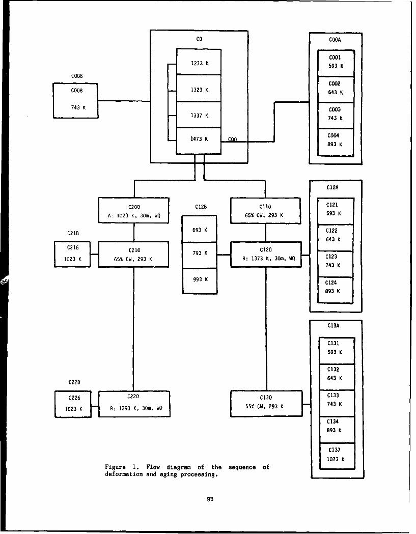
CO COOA
cool1273 K 593 K
COOBCo02
COOB 1323 K 643 K
743 K C003
743 K
1473 K a~n C004
893 K
C12A
C200 C12B Clio C121
A: 1023 K, 30m. WQ 65% CW, 293 K ,593 K
C21B 693 K C122
T 643 K
C216C20C0F C210 793 K C2
1023 K 65% CW, 293 K R: 1373 K, 30m, WQ C123
' 743 K
993 K C124
893 K
C13A
C131
593 K
C132
C22B 643 K
C226JC220C130C133
1023 K R: 1293 K, 30m, WO 55% CW, 293 K 743 K
C134893 K
Figure 1. Flow diagram of the sequence of
deformation and aging processing.
93

Table 3 - Deformation and Aging Processing metal matrices starting from duplex, austenite-ferrite microstructures, with an exceptional
Proc. strong bonding between the two phases. ThisNo. Nature of Process allows the two matrices to be plastically
deformed up to very high levels of plasticCO ST: 1423 K or 1373 K or 1323 K or strain by rolling, extrusion and wire drawing,
1273 K, 30M, WQ. at room and elevated temperatures withoutCOo ST: 1423 K, 30M, WQ. debonding or failure of the interfaces. This newCOOA Aging hardening of COO, tvariable, manufacturing technology has the highest
T= constant. potential for the development of fibrous andCOOB Aging of COO, t, Tfconstants. laminate double metal matrices composites with
very good strength, formability, and fractureC1lO 65% CW at 392K of COO. toughness. The microstructural design startedC120 Recrystallization of C1LO: 1173 K, with materials which were casted and processed
30 M WQ. to control volume fractions of two matrices:C12A Age hardening of C120. austenite and ferrite with very strong andC130 55% CW OF C12. ductile interfaces. The morphology of theC13A Aging hardening of C130. composite was designed through the control of
the initial volume fractions of the twoC200 Sequencial aging of COO. matrices, the nature of the deformation processC210 65% CW at 293 K of C210. (rolling and wire drawing), its temperature, theC21B Annealing for superplasticity of C210 amounts of strains involved in each cycle andC220 Recrystallization of C210: 1293 K, intermediate thermomechanical treatments. Two
30M, WQ. morphologies were designed: fibrous andC22B Annealing for superplasticity of C220 laminated. The strength, formability and
fracture toughness of these composites werecontrolled mainly by: athermal, deformation-
which are part of those obtained in this induced and isothermal transformations designedresearch program are presented and discussed within each of the two original matrices; thebelow: nature of the interfaces; and the nature of the
interface phases.DESIGN OF STAINLESS COMPOSITES
DESIGN FOR LOW ACTIVATION AND VOIDThe methods used for the production of SWELLING RESISTANCE
composite materials may be grouped in two maincategories: The first category includes those It appears to be possible to simplify themethods in which two basic operations are storage of radioactive reactor components byinvolved: the fabrication of the strengthening developing materials, with reduced levels ofphase (fibers or laminae) and the subsequent long living transmutations, in which the inducedinsertion into a single matrix. The second radioactivity decays in a reasonable time tocategory includes those methods in which the such a level that the waste no longer requiresstrengthening phase is produced directly in the maintenance. The most serious safety andmatrix in a single operation or in a sequence of environmental concerns for fusion reactorsoperations. Each of these categories has its involve induced-radioactivity in the first-walladvantages and disadvantages, and in the blanket structure. Different elements
The first category offers very good control exhibit different nuclear behavior whenof the nature of the matrix, the nature of the bombarded by neutrons, resulting in a variety ofstrengthening phase and of the volume fraction activation products, activation levels, andof each phase. However, the control of the decay times. Obviously these factors depend onnature of the matrix/strengthening phases the neutron flux and spectrum, and on theinterfaces and the nature of the interface exposure time. However, one can conclude thatphaqes that may be produced during manufacturing the selection of materials can produceof the composite, is difficult. As a conseque- significant differences in the activation levelsnce, problems such as poor formability and poor and decay times after exposure. This work usedfracture toughness are inherited, the guidelines for the classification and
The second category offers very good control disposal of low level nuclear wastes that haveof the nature of the matrix/strengthening phase been established by the U.S. Nuclear Regulatoryinterfaces (which in many cases can be developed Commission (2). On the basis of theseas coherent or semicoherent), and of the nature guidelines, initial concentration limits wereof the interface phases. However, it has serious calculated for various common alloyinglimitations on: the range of matrices and elements.strengthening phases that can be designed and Previous work (3) showed that concentrationsmanufactured and on the range of their volume of Ni, Mo and N must be severely restricted infractions. steels considered for nuclear applications.
The work reported here addresses the design, Based on these considerations, nuclearmanufacture and testing of composites with two resistance input was obtained to the present
94

chemical design. Initial concentration limits fine dispersion of phosphides. One of the majorwere calculated for various common alloying ideas in this design concept is the creation ofelements, ten years after the shutdown of a multiple stable interfaces, which are expectedreactor, for the three waste classes for to act as sink for vacancies, thus reducing thefirst-wall and blanket structures, given void formation, and consequently reduce the void9MW/year/m2 exposure (4). swelling.
The limiting values were those for a givenelement when no other restricted element waspresent in the alloy. The "sum of fractions"rule applied if other restricted elements werepresent. In this case the concentrations of eachrestricted element were divided by itsallowable concentration and the fractions thusobtained for all restricted elements wereadded. The sum of these fractions was less thanunity.
Thus in the chemical design of thesecomposites, four major considerations were takeninto account: (1) partial substitution of Cr byAl and Si, and Ni by Mn (2) elevated temperaturestrength and microstructural stabilization (3)prevention of void swelling helium and hydrogenembrittlement and (4) low activation.
The substitution of Cr by Al and Si, instainless steels has her the subject of various Figure 2. Typical LASC3 microstrcture showinginvestigations (5 to 11). These results indicate the austenite and ferrite matrices in thethat the oxidation and corrosion resistance solution treated condition.would be comparable to conventional grades ofstainless steels: 304, 316 and PCA. However, 0*Ovirtually no data is available concerning their AUSTENITE (f)
elevated temperature deformation and aging 80- FERRITE (0) 0.8behaviors. Thus, in order to obtain theformation of a passive oxide film and insure aneffective corrosion resistance, the Al, Si and 60 0.6
Cr contents were kept at 6.7, 1.3 and 4.7 wt%respectively. The analysis of the work reportedin (12) shows that Mn has a much lower 40 0.4
activation than Ni and Mo. This makes it a muchbetter candidate as an austenite stabilizer inthe design of low activation stainless 20 0.2
composites. However, recent studies have shownthat in Mn-Cr austenitic steels, the voidformation responsible for swelling tended to be 1273 133 1373 1423suppressed in steels with a small amount of Ni TEMPERATURE, K
(13). Thus, the Mn content was adjusted in orderthat Ms is below room temperature and Mf is Figure 3. Effect of solution treatmentabove 77 K, and kept at 28 wt%. In order to temperature on the volume fraction of eachsimultaneously decrease the amount of void matrix.swelling, but insure a low level ofradioactivity, the Ni content was kept at 1.3 DESIGN FOR HELIUMwt%. EMBRI1TLt4ENT RESISTANCE
In order to increase the elevatedtemperature strength and thermally stabilize the Recently, significant studies have beenaustenite, small additions of Mo and N were kept carried out in order to minimize He and H2around 0.1 and 0.01 wt% respectively. In order embrittlement in stainless steels of the typeto increase the creep strength and the strength 304, 316 and PCA (4, 14 to 19). Preliminaryof the boundaries, 60 ppm of boron were added results show that this problem may be avoided on(14). low activation stainless composites by the
Two strong carbide formers, Ti and V, were creation of multiphase-interfaces and very fineadded in order to produce very fine dispersions dispersions of stable intra-granular MC carbidesof intragranular MC carbides which were designed and phosphides (14, 19, 20, 24). It appears thatas: elevated and high temperature strengtheners these very fine dispersions do act as traps forand as traps for He and H bubbles, thus He and H2 bubbles and permit them to cluster atpreventing them to cluster at grain boundaries, grain boundaries. Although the dispersion/For the same second purpose, P was introduced at matrix interface appears to play a significenta level of 0.02 wt% in order to produce a very part, virtually no information is available on
95

! 10 m 10 m 10 m
Figure 4. Effect of prior aging temperature on the COOB microstructures: a) 1323 K; b) 1373 K; c) 1423K.
the mechanisms by which this trapping may These three sets of manufacturing variablesoccur. are controlled by the solution treatment, i.e
the temperature, the time and the quenchingOPTIMIZATION OF SOLUTION TREATMENTS rate. During further microstructural development
they are controlled by the deformation, aging,Figure 2 is a typical microstructure of the transformation (athermal and deformation
Mn-Al-C-V composite (LASC3) after casting and induced) and recrystallization processing.thermomechanical processing, solution treated at Figure 3 shows the effect of the solution1423 K for 30 minutes and water quenching, i.e treatment temperature (STT), for a constantCOO. It shows a microstructure consisting of two solution treatment time (STt) of 30 minutes, onmetallic matrices: the austenite, Y(dark areas) the volume fraction of each matrix. Thus we canand the ferrite, a (light areas). In the design adjust the volume fraction of ferrite from justof these composites microstructures consisting below 0.4 to just above 0.6 by varying STTof two metallic matrices, three sets of between 1273 K and 1423 K. As previouslymanufacturing variables become very important: 500the volume fraction of each matrix: fy and fa~the solute concentration of each matrix CY and Caand the grain size of each matrix dY and d.
500
4400
300
o & 3 643 K C 002
1273 1323 1373 1423 0 743 K C 003
TEMPE RATURE , K 0 3K C 004
Figure 5. Effect of solution treatment 2 10 500temperature on the hardness uf CO T 1 M , 0 U R Smicrostructures aged at T-743 K and t-100 Figure 6. Age hardening behavior of 0Ohours. matrices.
96

t is
I4Vkaa
- / ~77-
~~~~~~~~~~~~~~~~~ +ro gn eprtr tlOhus ntemcotutrldvlpet fCQ
0~~~~~~~~~~~~A nr 9 ;c 9 K )83K )99 ;f 13K
z,~ ~ ~ 'in -) prio -ging teprtresos (t10husm ncrostructur th mal quitoetstaole. CTh
i ng t-i; 1)f Oft ho trate energyic interfaces bae eini to reoinate atr) o ire 'i hot 1 i ur l at 743 Kn 1423peritea, o re high energyity int ferace
V, , r ,. P, ret:f ir tnt Ii v7 row iiitie show Aaar t 132 K.ihpots n the n oti on a tret ent;tir i ,11 j~ r f thn' 4 an the ge wacrs trelctue t car hrmal uiftue composThe
r f't Yruv i a A ' in o f ir e . i crust rut r h w- irn fiur 4evhwlopmento
thoi' ii h koel mirarnt iow n tSF1' e enrg itra ces are~~ beinn 2 t o prdoiit at
r ri n, i "ni ) 'v h i ii upesi 1n fi 74 Y, 1423 d~sere of cupverdaurh i ng d evelop esi!" t, ;s(' ri rin ferit (i r n irfl rsrc url thew fertat ri y wa'Tus ter q'0 uen in fr m ent3
ou e in 'I(- -l l w3 el rt d to ca r n t tu '( om os t

fttS4
%1 I Fft~rp~rwt'WA
tni

consequent precipitation hardening effect. The PRODUCTION OF LAMINATED COMPOSITESmaximum precipitation hardening effect wasobserved at 743 K for an aging time of 100 Figure 9 shows the strain hardening behaviorhours. This is explained by the intertwinning of during the production of laminate composites invarious dispersions of fine precipitates. The the first cycle of deformation (CliOmetallographic data presented in figures 6 and 7 microstructures) and in the second cycle ofand X-ray diffraction analysis data of overaged deformation (C130 microstructures). Typicalconditions is consistent with the existence of laminate microstructures developed during thethe dispersions of the following carbides VC, first cycle are presented in figure 10a. FigureMn5C4 , Feo. 2Mn5 .4C2 and (FeMn)3AlC. Aging 14 a and b present typicalbetween 893 K and 993 K leads to early overaging laminate microstructures developed during thewhich is explained by the heterogeneous second cycle. It was observed that at thisprecipitation of the 5 Mn phase. The sequence of deformation temperature the austenite deformedphase transformations which occur during aging by the formation of deformation twins eitherat 893 K is presented in figures 8a (1 hour), 8b before and or after recrystallization. This was(2 hours), 8c (6 hours) and 7d (100 hours) which possible for following reasons: first Mn loweredshow: 8a, well developed precipitates within the considerably the stacking fault energy of theferrite and the begining of BMn precipitation at composite (11), second the calculated Mdthe a / a interfaces; 8b, well developed BMn temperature was below room temperature.precipitates at the a / a interfaces; 8c,formation of BMn at the y/ ainterface, side; AGE HARDENING OF RECRYSTALLIZED LAMINATES7d, intertwinning of various dispersions ofprecipitates in ferrite and grain boundaries. As shown in figure 1 the recrystallization
T*.- sequence of phase transformation which of the C110 microstructures (figure lOa)occurs during aging at 993 K is presented in produced the C120 microstructures (figure lOb).figures 8d (10 minutes), 8e (2 hours), 8f (5 The aging of C120 microstructures produced thehours) and 7e (100 hours), which show: 8d, fine C12A microstructures shown in figure 10: (c),precipitation of VC within the ferrite; 8e, (d), (e) and (f) developed during 100 hours ofcoarsening of the precipitates within the aging at 593 K, 643 K, 743 K and 893 Kferrite and formation of Mn phase at the Y/a respectively. The details presented in figureinterfaces; 8f, precipitation of fine fibrous Mn 10 are: a) the laminated matrices Y and a arecarbides within the austenite; 7e, begining of strengthened by transformation and deformationprecipitation of Mn carbides (light areas) hardening respectively; b) recrystallization ofwithin the ferrite and full development of the each matrix; c) no significant precipitationfibrous strengthening phase of the austenite. strengthening in a or in Y matrices; d) initialIn the temperature range 1023 K to 1173 K the stages of very fine precipitation in the(FeMn)3AlC carbide precipitation mainly at the matrix with the formation of PFZ in the ainterfaces, as shown in figure 8f. In this adjacent to the a/y interfaces; e) developmenttemperature range no 6Mn phase was observed to of uniformly distributed precipitates in only;occur. f) begining of the precipitation of Mn in the y
/a interface. Specimens aged at 743 K develops
500 Table 4 - Room Temperature Mechanical Behaviorof LASC3 (ksi, n = 2 X 10- 3 sec-1 ).
MECH. AGING TIME, HOURSMICRO~PROP.
400. 2 24 100 500
Cu 107 --- 100 ---
C 122 a 75 --- 81 ---T-643K % 42 --- 14 --
3C 130 au 190 186 200 ---
C 132 a 170 171 188 --T=643 K % 1 18 10 7 ---
ou 112 --- 96 90C 123 a 80 --- 82 84II I. T=743 K 1 31 --- 8 7
20 40 60
% DEF0RMATI0N C, 192 --- 155 145C 133 a 175 --- 131 134
Figure 9. Strain hardening behavior during the T-743 K %1I 12 --- 9 5production of laminate composites.
99

a'
4, 1. ?*0
~~4_
I+I
i~rIn iircr znle1 laminates: a) ('110 Laminate; b) C120 recrystallizedirs50 r) W~ ' 643 K; 1)43 K and f ) 893 K.
;o i'rf .'fr Ow r L th errease in strength and ductility appears to
1 1 7i B le with t01 1) isi oi! c iO jat ed witLh the formation of the AICr
/ . itr 1>1.phase.
11 (GL' lAR1)NI Nh( 01' ;X)131,1 i AM INATF-S- . . - * iho 1" i i' i
* s Oi ri 1,7 t, age firrdening response of ('1303 Lami nates
;hJB LW i howni i n f igures '), 12, 13 and I). Typical
I~~~~~ mi ' 4'irrrstrurtures ;lrB presented in fi gore 14,
-;!),iwwi rli: A) I'. wt m ic rest ruc tutre showinfg;t nJti 'I 1 t ro-nOg herring~ of th" I arid matrices by
L,'' r~isfornmwt ioni ;iw Iif oriittin hardening; 1))
1 ',I he .'nri i eterogoeus precipitation; c)
1 1,2 v',rv f ir no )rkB-i 1)i t~o ion i n ferrite with
* .* I . *i',t.rT- ' i-or) f prio ipiteiteo troo z~urrs J11' ) )

40040
300 70 p _ 20
I I I C 121 0 C 131
573 673 773 873 973 M % EL [ E
T EM PE RA TU RE, K -
2 24 100 500
Figure 11. Effect of aging temperature on the T IME , HOUR S
hardening behavior of C120 composites, t=100hours. Figure 13. Effect of prior aging time and
temperatureon the mechanical properties of C121600 and 0131 laminate composites.
As shown aging at 593 K produced very highstrength and good ductility. Typicalmicrostructures are shown in figures 14b and18b. Aging at 643 K leads to precipitationwithin the ferrite matrix: VC, AlCr and FeMn4.
500 -At 743 K the precipitation starts taking placein the austenite matrix and at 893 k coarseningis observed, and a Mn nucleates at interfaces.The sharp decrease in strength and ductilityobserved at 893 K (figure 15) is attributed to
Dthe formation of the 8Mn phase.V7 No a Mn or sigma phases were observed on
400 aging at 1073 K or above up to 100 hours. Thisis explained by the higher solubility of Mn inthe austenite matrix at elevated and hightemperatures. An extraordinary increasesimultaneously in ductility and strength wasobserved above 893 k. At 1073 K typical values
obtained were au-125 ksi, EL-31 %, for aging
Table 5 - Room Temperature Mechanical Behavior0 593 K C 131 of LASC3 ( ksi, & -2 X 10- 3 sec-1 )a643 K C 1320 743 K C 1330 593 K C 121A 643 K C 122 AGING TEMP., T-1023 K0 743 K C 123 MECH.
200 1 1 1 1 MICRO AGING TIME, HOURS2 24 100 500 PROP.
TIME, HOURS 24 100
Figure 12. Effect of prior aging time andtemperature on the hardening behavior of C121 °u 103 99and C131 laminate composites. C 215 al 70 68
% l 38 36C133 significant homogeneous and heterogeneousprecipitation in the deformation twins withinthe austenite matrix and in slip bands in within u 101 100the ferrite matrix; e) coarsening of C 225 a 67 65precipitates in ferrite and at grain boundaries; % 11 40 37f) precipitation of secondary equiaxed ferritewithin the austenite.
101

7wm mv
- r -f
~e~t&17r,

273 _40060
EL'I C 215
C-0C2240
o 300
20
200 I I573 673 773 R73 97) 1073 2 24 100
T[4PE0RiR[ TIME , HOURS
Figure 15. Effect of prior aging temperature Figure 17. Effect of prior annealing time on the(t=24 H) on the room temperature mechanical high temperature annealing behavior of C215 andproperties of C13A composites. C225 composites.
a superplasticity in C216 due to the production ofsecondary ferrite in laminated austenite. Figure18 compares the morphologies developed by singleand double lamination of solution treated andsingle lamination of aged matrices. It shows: a)C121 aging of partial spheroidized laminatedmatrices; b) C131 aging of double laminatedmatrices; c) tri-dimensional representation of
, , b); d) C216 precipitation strengthening offerrite and austenite matrices during annealingfor superplasticity for 30 minutes at 1023 K.
ELEVATED AND HIGH TEMPERATUREMECHANICAL BEHAVIOR
10 jum
In addition to 293 K two other temperatureswere selected for tensile testing. The first 593K was above 0.3 of the melting point (Tm) andwas selected for the elevated temperaturebehaviour. The second 1073 K, was just above 0.6Tm was selected for the high temperaturebefaviour. Figure 15 and Table 6 show thatLASC3: C121, C131, C215 and C225 exhibited verygood microstructural stability with no brittlephases precipitating during aging up to 500hours.
C22B and C21B microstructures were tested at1073 K with a strain rate of 2 x 10⁻⁴ sec- 1. TheC21B exhibited an elongation of 180 %. This isexplained by the formation of very fine grainsof ferrite inside the austenite as shown in
1figure 16b, which was not present in the C22Bmicrostructure. C121 and C131 specimens were
Figure 16. Thermal stability of C22B and C21B also tested at 573 K with a strain rate ofcomposites aged at 1023 for 100 hours. 2 x 10⁻³ sec--. Both specimens did show a
decrease of strength when tested at 593 K.hours. The mechanical behaviour is shown in However the drop in strength from 293 K to 593figure 17 and table 5. K, was very small, 25 ksi max, both C121 and for
C131. Table 6 presents results of tensileCOMPOSITE MORPHOLOGIES properties tested at 593 K and 1073 K.
These results represent a considerableFigure 16a and 16b compare the C226 and C216 improvement on the best duplex alloys which
morphologies developed during the lamination of exhibit superplasticity under certainaged matrices. They show the development of microstructural and deformation conditions:
ultra fine grained stable duplex equiaxed
103

aa
illm 4nlu
Fiue-a Marcsadsrnteigpae opoois ia C1,b)13agdfr2 hor; c)
I }
I
Tridimensioalrepresentation of C131 and d) C215 composites aged for 30 minutes.
structures, deformed at about 0.5 Tm and a lower SUMMARY AND CONCLUSIONSstrain rate (21). Their best result obtained ona duplex stainless steel showed an elongation of The microstructural development during95.7 % at 1098 k with a strain rate of 2.8 x deformation and aging, mechanical and thermal10-4 sec-I (21). behavior of low activation stainless composites
have been studied. Four different sequences ofTable 6- Elevated and High Temperature microstructural development were designed: C12A,
Mechanical Behavior of LASC3 (Aied: CI3A, C21B and C22B with followingT=1023 K, t-24 H , £ 2 X 10⁻⁴ sec-), characteristics:
PROPERTY ou Gy %El C12A: good combination of strength and ductility
%at 593 K (better than duplex stainless steels).MICRO ksi ksi
C13A: Ductile fracture with very high strengthat 593 K. Decrease of strength and ductility due
C121 89 48 50 to formation of $Mn phase. Large increase in593 K strength and ductility above 993 K due to the
formation of the secondary ferrite within theC131 164 130 15 austenite and the absence of any brittle
phases.
C215 8 -- 180 C21B: Very good combination of strength and1073 K ductility after annealing at 1023 K, due to
absence of any brittle phases and to a highC225 15 -- 61 thermal stability, and to the precipitation of
104

secondary ferrite in the austenite. 21. Afonja,A.A., in "Duplex Stainless Steels"Ed. Lula,R.A., ASM (1983) 143.
C22B: Similar behavior to C21B at room 22. Solomon,H.D. and Devine,T.M. in "Duplextemperature and after annealing at 1023 K. Fine, Stainless Steels" Ed Lula R.A., ASM (1983)fibrous precipitation of Mn carbides in the 693.austenite. 23. Klueh,R.L. and Tanaka,M.P., J. Metals 16
(1985).The tensile properties of the C121 and C131 at 24. Marquis,F.D.S., unpublished work on Fe-Mn-593 K are almost the same as at room Al-C-X-Y Low Activation Composites.temperature, this means high thermal stablity at593 K. Thus LASC3 has the potential to be usedsafely at 593 K. However further work is neededto evaluate its performance under irradiationconditions.
A high degree of superplasticity can be achievedin these composites with two laminated matrices:ferrite and austenite and the development ofsecondary equiaxed ferrite within the austenitematrix.
REFERENCES
1. Kesternich,W., Meertens,D., Acta Met. 34,6(1986) 1071.
2. Nuclear Regulatory Commision, 10 CFR Part61, Federal Registry 47, 248 (1982) 57446.
3. KluehR.L. and Bloom,E.E., in "OptimizingMaterials for Nuclear Applications",Ed. byGarner,F.A., Gelles,D.S. and Witten,F.W.,Pubi. TMS, AIME (1973) 73.
4. BosquezA.G. and Kesternich,W., Scripta Met.19 (1985) 57.
5. Banerji,S.K., Metal Progress (1978) 59.6. Charles,J., Berghezan,A., Lutts,A. and
Dancoisne,P.L., Metal Progress (1981) 71.7. Floreau,S., Met. Trans. 13A (1982) 2003.8. Muca,B., These de Docteur-Ingenier,
Universite P. et M. Curie (1983).9. Dunning,T.S., Glen,M.L. and Leavenworth,
H.W., Metal Progress (1984) 19.10. Benz,J.C. and Leavenworth,H.W., J. Metals.
(1985) 36.11. Kim,Y.G., Park,Y.S. and Han,J.K., Met.
Trans. 16A (1985) 1689.12. Conn,R.W., Bloom,E.E., Davis,J.W.,
Gold,R.E., Little,R., Schultz,K.R.,SrnithD.L., Wiffen,F.W., Fusion, 5 (1984)291.
13. Takahashi,H., TakeyamaT., Tanikawa,K.,Mivra,R., J. Nucl. Mater. 133/4 (1985) 566.
14. Kesternich,W., and Rothaut,T., J. Nucl.Mater. 103/4 (1981) 845.
15. Thiele,B.A., Diehl,H., Nuclear Technology 66(1984) 597.
16. Watanable,K.T., Kondo,T., Nuclear Technology66 (1984) 630.
17. Yamamioto,N., Shiraishi,H., Kamitsubo,H.,Kohno,I. and Shikata,T., J. Nucl. Mater.133/4 (1985) 493.
18. Dsvis,J.W., Fusion Technology 8 (1985)1931.
19 Marquis,F.D.S., unpublished work on Fe-Ni-Cr-C-X-Y Multiphase Stainless Steels.
20 Msziasz,P.J.,'Micon 86", ASTh STP 9-/9 (1986)116.
105

INFLUENCE OF DYNAMIC STRAIN AGING ON THE WORKHARDENING OF A Fe.Mn-AI STEEL IN THE TEMPERATURE
RANGE 20 TO 7000C
Cristina Godoy, Berenice Gonzalez, Paulo Roberto Cetlin,Evando Mirra de Paula e Silva
Dept. of Met. Engr., Fed. Univers. atMinas Gerais, Belo Horizonte, Brazil
ABSTRACT EXPERIMENTAL PROCEDURESThe effects of dynamic strain aging on A 2,5kg ingot was produced in an inductionthe strain hardening behaviour of an furnace with the following averageaustenitic Fe-Mn-Al-Si alloy containing composition: 0,13%C; l,l%Si; 6,7%Al0,13%C were investigated by means of 37,3%ML1, balance Fe. The ingot was forgedtensile tests performed in the tempera- at 900-11000 C down to square sectionture range 20 to 700 0 C at a strain rate bars 10 x 10mm. After the last forgingof 6,0 x 10- 4 s- 1. The work hardening step, the bars were held at 1100 0 C forcoefficient was determined from "log o 15 minutes and water quenched. The barsversus log c" plots and two stages of were then cold rolled down to a 2mmdeformation were observed at lower tem- thickness, and the material was annealedperatures. Curves of the work hardening for I hour at 900 0 C. Flat tensile specimenscoefficient as a function of temperatu- were then machined with a 27,7mm gagere showed two peaks at 300 and 550 C , length and 1,08mm thickness. Tensilecorresponding to the two stages of de- testing was performed in a INSTRON modelformation. Analysis of the difference TTO, under an Argon atmosphere; crossheadin the intensity of these two peaks speed was 0,1cm/min, leading to a strainsuggests that it is due to different rate E = 6,0 x 10- 4 sec -1 . The tempe-mechanisms of aging operating in the rature range was 20-7000 C. Tensiledifferent temperatures. specimens grip ends were cut for metallo-
graphic and X-Rays analysis.EXPERIMENTAL RESULTS
DYNAMIC STRAIN AGING (DSA) in austeni- The microstructure of the alloy consistedtic alloys is being studied at length(l, 2 ) ; of only one phase, the austenite,withmany aspects of the phenomenon remain ASTM grain size 5.X-Rays analysis confirmedto be clarified. The mechanisms invol- the presence of this phase,which had aved in DSA, in this case, are the in- 3,667A lattice parameter. Serratedteraction of dislocations with vacancy/ yielding was observed in the stress-interstitials associations, or of dis- strain curves in the temperature inter-locations with substitutionals. The val 200°C-5500 C. Figure I shows yieldneed of consideration of the association and tensile strength as a function ofof point defects is a consequence of the temperature.values of the dislocation/intersticial The work hardening coefficient ninteraction energy for these alloys,which and the coefficient K from Hollomon'sis lower than for CCC systems. equation a = kEn was evaluated through
The study of the evolution of the a computer program, to which 40 to 60work hardening exponent and of work harden- true stress-true strain data pointsing rate with testing temperature when were fed. These pairs were taken beforeconsidered in its different regions, the onset of necking. Curves of logconfirm the proposed mechanisms for DSA a x log E (fig.2) show that one actuallyin FCC systems. This is shown in the has two linear ranges, whose size ispresent paper for an austenitic Fe-Mn-Al-Si temperature dependent. As temperaturealloy with 0,13%C. rises, the slopes of the two straight
107

lines get closer, till only one slope is and 550 0 C, due to dynamic strain aging.observed. The slope of the higher strain 2. Log a x log e curves have shown twoline was always higher than that of the stages, leading to two values of thelower strain range. Figure 3 shows the work hardening exponent n, which wereevolution of n with temperature for both smaller for the first stage.ranges. Figure 4 shows the change in 3. Curves of do/dc versus temperaturetrue stress at different strain levels have shown peaks whose amplitude dependswith temperature. In order to analyse on temperature and strain level(ist orthe work hardening behavior in both 2nd stage). Higher peaks were observedranges, the parameter do/dc = Knenl around 600 C, and these were consideredwas calculated for e = 5% and for as coming from Aluminum atmospheresE = 12%, using the values of n and K formed in the dislocations stress fields.from the computer program, which are The peaks at 3000C are small, and thislisted in Table 1. The change of do/dE was attributed to the mechanism ofwith temperature is shown in fig.5. reorientation of pairs vacancy/carbon
DISCUSSION atoms, in the stress fields of dislocations.Curves in fig.l show an anomalous behaviour, The 300°C peak at higher strain in evenwhich were identified in a previous smaller, probably due to a smaller ratiopaper(l) as due to dynamic strain aging. dislocation density/number of vacancies.The 3000C peak was interpreted as REFERENCESresulting of a reordering of vacancy/ i. Hannula,S.P.; Korhonen,M.A. and Li,carbon atoms pairs in the dislocation C.Y.; Met.Trans. A, 17A, 1757-67(1986).stress fields, following a Snoek-Schoek 2. Cribb,E.R. and Reed-Hill, R.E.; Met.mechanism. It has been suggested that Trans. A, 8A, 71-76 (1983).the 550°C peak is caused by the inter- 3. Godoy,C. and Paula e Silva,E.M.; A-ation of dislocations with substitu - nais do XXXVIII Congresso Anualda ABM,cionals, involving long range diffusion 2, 187-97 (1983).and following Cottrell's model. In the 4. Jenking,C.F. and Smith,G.V.; Trans-prcsent case, the substitutional would action of the Metallurgical Society ofbe the Aluminum. Aime, 245, 2149, 56 (1969).
The curves in fig.4 also showed 5. Reed-HillR.E.; Reviews on the De-peaks at the above mentioned tempera- formation Behavior of Materials 2,tures, as observed for FCC systems by 217-42 (1977).other authors( 4 ). The work hardeningcurves in fig.5 also show peaks around300 C and 500-600 0 C, instead of showinga smoolh decrease in n, which is typicalof materials where DSA is not observed.
For the 5% curve (Fig.5), the 3000 Cpeak associated with a Snoek-Schoekmechanism is not very strong probablydue to the weak pinning typical of thisinteraction. The strong peak at 600 0 Cwould be due to formation of Aluminumatmospheres around the dislocations,leading to a strong Cottrel pinning.
The 3000C peak in the 12% curve(Fig.5) is -acaker than for the 5% curve.At 12% strain both vacancy concentration
and dislocation density are higher thanfor 5%, and it is possible that thenumber of pairs undergoing reorientationis lower for 12% strain. The secondpeak in the 12% curve (Fig.5) is at atemperature lower than in the 5% curve.This is probably due to a higher diffusionof Aluminum caused by the higher vacancyconcentration. There is probably aninteraction between the two peaks inthe 12% curve, making difficult acomparison of the second peak for 5%and 12% strain.
CONCLUSIONSI. The curves for the change with tem-perature of the flow stress at differentstrain levels, shnwed peaks around 3000 C
108

Table 1 - Values of n, k and correction coefficient (s) at different temperatures
Stage I Stage II
TEMPERATURE n K(MN/m ) s n K/MN/m 2 s
20 0 C 0,24 83 0,988 0,48 145 0,999
200 0 C 0,37 77 0,996 0,63 139 0,999
300 0 C 0,38 77 0,999 0,63 135 0,999
400°C 0,32 64 0,998 0,59 122 0,998
500°C 0,29 58 0,989 0,56 117 0,999
550 0 C 0,34 61 0,989 0,52 95 0,999
600 0 C 0,36 63 0,999 0,49 86 0,997
650 0C 0,32 51 0,999 0,42 68 0,996
700°C 0,38 53 0,999 0,30 44 0,980
109

0 0
-- natoo
0
_ I II
4)O W
0 0 0 Lzz
110
i IlI lI n
U))
41-8 -4
,4
00 1
it
4a
0 4
0
00
0 0 0 0 0 00 0 0 0 0
110

mA wc
P.
uco 0 . .0a 0 0 0aJ
00 0 0 Q0 0
\\I \t\
-4
00
-,4
0p
-,4
w
E-4
10W,
K I-N 4
r- - r-
12w/NIM) SS311JLS 3nlW.

W F4
0 0
-4
cr.
0. .-
'44Q) 4)o 00
o0.0
Inn
$4)
0
I-q
0
14
0.
001
00
00
In 44
.LN3NOdX3 ONIN308VH MHOM
112

4 3,8 PLASTIC STRAINS
3,6 0,05N '0,02E3,4- a 0,002
z , 0 0,002
23,2-
3,0
I'_
r2,6-
2,4-
2,2-
2,0-
1,8
1,6
1.4-
1,2-
100 200 300 400 500 600 700 800
TEMPERATURE (OC)
Figure 4 - Evolution of true stress atdifferent strains with tem-perature. i-6,0x10
4 s- 1
113

~20
19 _W
I-I
z
z
W\
17
16
15-
i , II I,
1411
3I I .I 0/
121