Precast Segmental Substructure System for Standard … Journal/1999/July-Aug... · economy in...
18
A Precast Segmental Substructure System for Standard Bridges 56 Sarah L. Billington, Ph.D. Ass istant Professor of Structural Engineering Cornell University Ithaca, New York Robert W. Barnes Graduate Research Assistant The University of Texas at Austin Austin, Texas john E. Breen, Ph.D., P. E. Nasser I. AI-Rash id Professor of Civi l Eng ineering The University of Texas at Austin Austin, Texas A precast seg me nt al substructure system for standardizatio n is presented. This system is int e nd ed to s upp ort precast concrete girder s up erst ru ctures in non-seismic regions and provides an alte rn ati ve to current cast-in-place systems , particularly for areas where reduced construction time is desired. The substructure syste m is made up of predominantly precast e lem e nts. F ou r different co lumn sizes w ith one basic cap shape are proposed to be assembled as si ngle co lumn , stradd le and frame bents for varying heights and widths of standard bridges. Precasting all ows for in creased use of high performance concrete in the substructures, thus improv in g durability. In addition , the greater co mpressi ve st re ngt h of the high performance concrete is utilized to reduce the handling weight and dead l oad of the substructure units, facilitating co nstruction. The construction method proposed wi ll significantly shorten on-site construction time. Shortened co nstru ct ion time, in turn, leads to important safety and economic advantages when traffic disruption or rerouting is necessary. W hen designed for economy and function alone, standard highway bridges often detract from , rather than enhance, the environment in which they are built. This result does little to show the exciting developments being made in structural engineering. In re- cent years, an effort has been made to further improve economy in construction of bridge superstructures through PCI JOURNAL
Transcript of Precast Segmental Substructure System for Standard … Journal/1999/July-Aug... · economy in...

A Precast Segmental Substructure System for Standard Bridges
56
Sarah L. Billington, Ph.D. Ass istant Professor of
Structura l Engineering Cornel l University Ithaca, New York
Robert W. Barnes Graduate Research Assistant The U niversity of Texas at Austin Austin , Texas
john E. Breen, Ph.D., P.E. Nasser I. AI-Rash id Professor
of Civi l Eng ineering The Univers ity of Texas at Aust in
Austin , Texas
A precast segm ental substructure system for standardization is presented. This system is inte nded to support precast concrete girder superstru ctures in non-seismic regions and provides an alternative to current cast-in-place systems, particularly for areas where reduced construction time is desired. The substructure system is made up of predominantly precast e lements. Four different column sizes w ith one basic cap shape are proposed to be assembled as sing le co lumn, straddle and frame bents for varying heights and widths of standard bridges. Precasting allows for in creased use of high performance concrete in the substructures, thus improving durability. In addition, the greater compress ive stre ngth of the high performance concrete is utilized to reduce the handling weight and dead load of the substructure units, faci litating construction. The construction method proposed will significantly shorten on-site construction time. Shortened construction time, in turn, leads to important safety and economic advantages when traffic disruption or rerouting is necessary.
When designed for economy and function alone, standard highway bridges often detract from, rather than enhance, the environment in which
they are built. This result does little to show the exciting developments being made in structural engineering. In recent years, an effort has been made to further improve economy in construction of bridge superstructures through
PCI JOURNAL

precasting. In many cases, this has had a positive impact on the aesthetics of standard bridges. On the other hand, less attention has been paid to bridge substructures, which are often the most visible part of standard highway bridges.
Cast-in-place substructures can be formed in many ways for attractive results. However, cast-in-place substructure construction can also lead to extensive traffic delays and rerouting inconveniences (see Fig. 1). Cast-inplace substructures often lack durability, particularly in aggressive environments.' This is particularly true with older cast-in-place substructures. Numerous efforts have been made recently to address durability, but the results cannot yet be adequately assessed.
Precasting offers an alternative for substructure design that can have attractive , durable results and move much of the substructure fabrication off-site and into the precasting plant. The efficiency of mass production and the high level of quality control of fabrication in a precasting plant have made precast superstructure elements a highly economical form of construction. These same techniques may be applied to substructure elements. Onsite labor and construction time will be shortened, thus substantially reducing traffic delays and rerouting during construction. High performance concrete may be used more consistently with higher quality control in a precasting plant.
Recognizing that the consideration of aesthetics in bridge design and, in particular, bridge substructures is given a low priority in many engineering offices and is not stressed in the typical engineering curricula, a research project was funded by the Texas Department of Transportation (TxDOT) and conducted by the University of Texas at Austin through the Center for Transportation Research (CTR) to study the aesthetics and efficiency of Texas' short- and moderatespan bridges and their substructure systems. The subject of this paper is a portion of this project and has applications to short- and moderate-span bridges in many regions of North America and throughout the world. 2
July-August 1999
Fig. 1. Extensive on-site equipment for cast-in-place multi-column bents.
BACKGROUND
The current common overall concept in many states for bridge substructure design and construction3 has changed little in the last 40 years. Driven by considerations of economy and wide reuse of form systems, castin-place circular columns with cast-in-
Fig. 2. Precast substructure for U.S. Highway 183 in Austin , Texas.
place rectangular bent caps constitute the most widely used system. During the rush to greatly expand the transportation infrastructure during this period, emphasis on aesthetics was given a lower priority. Aesthetic creativity was limited by the repetitive use of similar shapes for every project for economic savings.
57

While this substructure system of circular columns and rectangular caps is visually awkward, it has also not proven to be a durable system. Durability has been a problem in coastal regions, where saltwater spray and wicking are prevalent; in northern regions where deicing salts applied to decks are carried through the joints and aggressively attack the caps and columns; and in regions where high sulfate soils exist.
Most authorities agree that two of the most effective measures to increase durability are to decrease concrete permeability and to increase concrete cover. High performance concrete for precast superstructure design has been shown to have extremely low permeability, affording increased protection. The most practical way of introducing high performance concrete into substructures is to precast substructure elements. The high quality control at precasting plants also allows for a more reliable cover of reinforcement.
Precast Substructure Systems
Since the introduction of precast segmental construction to the United States (JFK Causeway in Corpus Christi, Texas, 1971), a large number of segmental box girder superstructure bridges have been completed. This method of construction for box girder superstructures has proven to be economical, particularly for highly repetitive moderate-span as well as long-span projects. The state-of-theart for segmental construction is
Fig. 4. Precast hollow concrete pier segments were lowered into position from the deck above at Linn Cove Viaduct in North Carolina.5
evolving, as this bridge type has resulted in bridges that are both elegant and durable.•
The application of precast segmental technology to substructure design has been more limited. In particular, the use of segmental construction techniques for shorter-span bridge substructures [spans less than 105 ft ( 45 m)] has been explored very little yet the potential benefits of a system incorporating this technology are very
Fig. 3. Precast substructure for U.S. Highway 249 over Louetta Road in Houston, Texas.
58
promising. Two recently completed examples of applying precast segmental technology to shorter-span bridge substructures in Texas were for U.S . Highway 183 in Austin (see Fig. 2), and State Highway 249 over Louetta Road in Houston (see Fig. 3).
Other examples of precast substructure design in the past show that precasting has been used for a variety of project types with a variety of different substructure elements being precast. Precasting substructures is not and has not been limited to precast segmental construction. At the Linn Cove Viaduct in North Carolina, hollow pier elements were precast and then lowered into place from the newly constructed superstructure to minimize construction impact on the site below and thus preserve the environment (see Fig. 4). 5 Precast piers were also used at Vail Pass in Colorado to minimize site impact (see Fig. 5).6
At Redfish Bay in Texas, precast pile caps were placed over precast piles to construct a long low-water crossing (see Fig. 6).7 Precasting the pile caps saved the contractor six months of construction time by avoiding the need to place fresh concrete over water. Precasting also provided better quality control for concrete placement. Precast columns were used for the Seabreeze Bridge in Vol usia County, Florida. Precast caisson elements have been used for a number of water crossings to speed construction.•·•
The high quality control of concrete fabrication in a precast plant was used advantageously for hollow column segments that support an ocean pier in South Africa. 10 The interlocking, stacked , hollow column segments were used as a dense corrosion-resistant form that was filled with trernie concrete. The largest bridge project carried out in the Middle East as of December 1989 was the Bahrain Causeway, which was constructed almost entirely out of precast elements.11
Pile foundations, pile caps and pier shafts for six pile groups on either side of the three main spans of this causeway were all precast. Precast hammerhead caps have also been used in the past to top cast-in-place columns.
PCI JOURNAL
Pretr~sing tendons
A
A recent project using precast substructure elements for a moderate span precast girder bridge is the Edison Bridge over the Caloosahatchee River in Fort Myers, Florida, designed by HDR Engineering, Inc.* The precast substructure units used non-prestressed reinforcement connected with grouted sleeve couplers. The largest column segment weighed 89 kips (395 kN). The caps were up to 61 ft ( 18.5 m) long with the largest cap segment weighing 155 kips (690 kN).
In 1992 dollars, the precast column bid prices were $445 per cu yd ($580 per m3) and the precast caps averaged $560 per cu yd ($730 per m3). The
* van der V een, T . A., "Precasting the Ed ison Bridge," PCI Convention presentation, October 1992, Nashville, Tennessee.
Fig. 5. Schematic drawing (A)6 and as-built view (B) of precast concrete piers for Vail Pass in Colorado.
sub structure bid prices composed roughly 7.5 percent of the total bridge bid price.
A preliminary study for developing precast bridge substructures that could be standardized for moderate- span bridges, in particular moderate-span water crossings, was completed for the Florida DOT in May 1996 by LoBuono, Armstrong & Associates, HDR Engineering, Inc. and Morales and Shu mer Engineers, Inc. 12
A number of precast substructure options for pile bent caps and for columns and caps for multi-column and hammerhead bents were identified. Consultants and representatives from the contracting and precasting industries rated different shapes and fabrication options. A recommendation was made to limit precas t ele-
ment weights to 120 kips (530 kN) and to limjt the number of necessary connections.
Past projects and recent developments, although limited in number, have shown that precasting substructure elements is feasible and advantageous for a wide variety of project types. New applications for precast substructure elements continue to be explored.
CRITERIA FOR PROPOSED PRECAST
SUBSTRUCTURE SYSTEM The criteria for the proposed precast
substructure system were that the system must be:
1. Compatible with precast concrete beam superstructures.
Fig. 6 (left and right). Erection of precast pile caps for Redfish Bay, Texas, low water crossing.
July-August 1999 59

2. Economically competitive with current practice.
3. Sized for fabrication and erection with existing plants and construction equipment.
4. Compatible with precaster and contractor experience.
5. Durable. 6. Designed in accordance with cur
rent design specifications. 13•14
•15
·16
7. Applicable to a wide range of project types.
For compatibility with existing precast plants and construction equipment, element weights should be kept below 160 to 170 kips (700 to 750 kN) . (This range represents roughly the weight of the largest prefabricated beams used in Texas.)
ELEMENTS OF PROPOSED SYSTEM
A precast single-column bent is depicted in Fig. 7. The substructure is made up of three basic segment types: column segments, a "template" segment and inverted-T cap segments. Inverted-T caps were chosen over rectangular bent caps for this system for reasons of improved visibility through the substructure as well as increased clearance underneath the substructure. Inverted T -caps also allow for a lower overall structure height.
Precast template
Fig. 7. Elements of precast pier.
60
There are two areas specified for on-site geometry control within these substructures: a joint at the base under the first precast column segment and a joint at the top of the column shaft beneath the top precast column piece (the "template"). These two joints are cast-in-place with a high quality concrete. The other joints between precast segments are match cast and epoxy filled. The design criteria for the substructure units made up of these precast elements are outlined in Ref. 2.
To maximize both constructi on speed and substructure durability, a system of match-cast segments with epoxy joints was developed. While "loose fit" precast segments joined in place with mortar joints is an option for precast substructures, it is not proposed for this system that focuses on construction speed and durability.
Match-casting of column segments is relatively simple and can be performed at a rate of at least one segment per day per casting machine. Control of alignment during matchcasting in the casting yard allows for rapid segment placement on the construction site. This is in contrast to "loose fit" precasting with many field cast mortar joints where alignment must be taken care of on-site for each segment during erection . In addition, careful measures to ensure mortar
Precast Inverted-T Cap, Pretensioned
Adjustable supports
(geometry control joint)
Match-cast "perfect fit" joints
Adjustable supports
(geometry control joint)
durability at every joint of "loose fit" precast segments would be required. Both of these requirements would be a major drawback for the proposed system, developed to speed up on-site construction.
Epoxy joints are proposed for the match-cast segments rather than dry joints because dry joints are prohibited in Texas and the durability record of epoxy joints is excellent. With the proposed system, it is still necessary to have two cast-in-place alignment joints in each of the otherwise matchcast piers. The joint material placed in these locations must be durable and the tendons protected.
Pier Segments
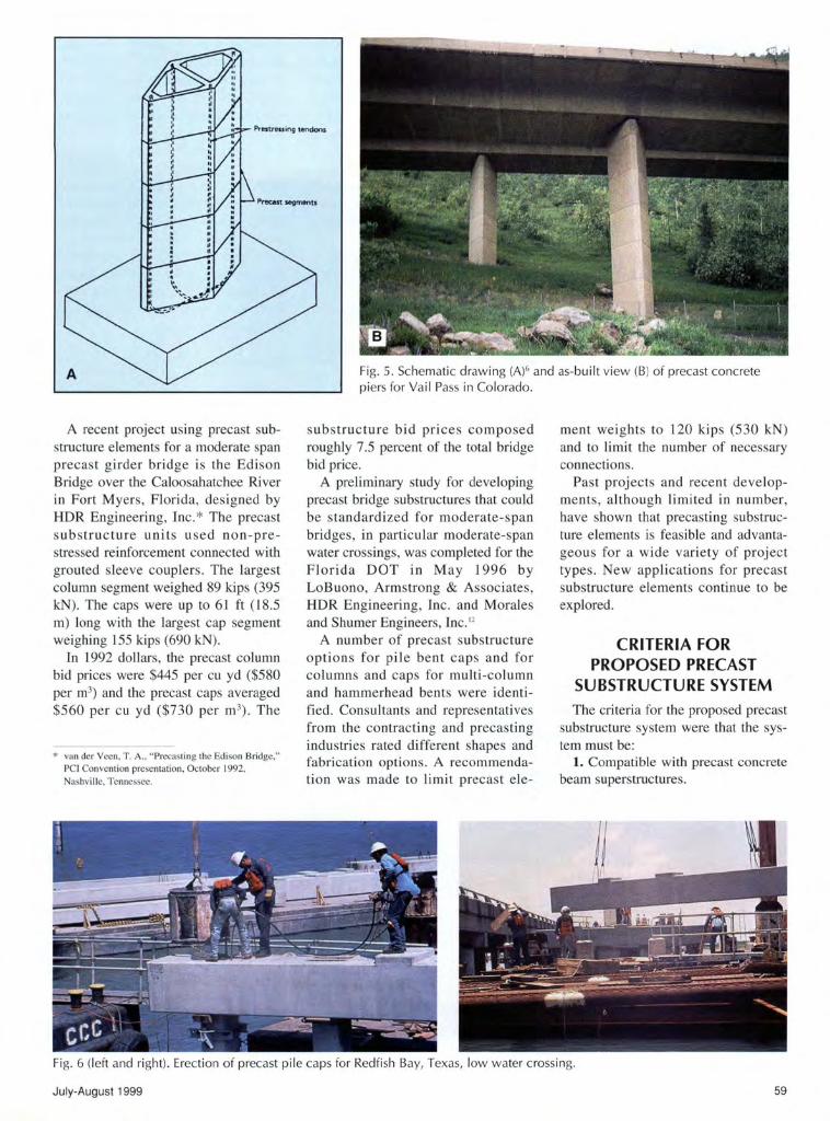
Four hollow column segment sizes were designed (see Fig. 8) . Column segments are hollow to reduce the weight of the elements for hauling and erection. These sections were developed for use with high performance concretes with strengths of 6000 to 10,000 psi (41 to 70 MPa).
The dimension transverse to the cap of all pier segments [48 in. (1200 mm)] corresponds to the width of the cap stem. These matching dimensions improve aesthetics and facilitate the continuation and anchorage of post-tensioning steel (bars alone or both bars and strands) from the column into the cap. Post-tensioning bars would be coupled to anchors cast into foundation caps. Post-tensioning strand would be threaded from the top of the cap into ducts passing through a 180-degree turn in the foundation cap, resulting in both ends of the strand exiting the top of the cap (see Fig. 16). Thus, all strand anchorages and posttensioning operations are performed at the top of the cap.
Pier segments can be cast in 24, 48, and 96 in. (600, 1200, and 2400 mm) heights. The wall thickness and concrete covers for the piers can easily accommodate inserts or form1iners attached to the formwork.
Shear keys are provided at the chamfered corners. The walls of the hollow pier segments provide room for post-tensioning bars of up to 13/s in. (36 mm) with a strength of 150 or 160 ksi (1030 or llOO MPa) as well as multi-strand tendons up to the cur-
PCI JOURNAL
P12
j,. 1200mm .. 1 Shear key
Post-tensioning
P18
P30
E E
~ ~
1 .. 1BOOmm
Post-tensioning bars on long face
-I P12 P1B P24 P30
Segment weights for a 2.4m Bft. s ment:
5BkN (13k) BOkN (1Bk) 102kN (23k) 124kN (2Bk)
P24 strand or bars on ends --.t.;;..;....-14-
0 0 0 0
0 0 0 0
1 .. 2400mm
Fig. 8. Four pier cross sections.
rent 19K6 size made up of nineteen 0.6 in. (15.2 mm) strands with a strength of 270 ksi (1860 MPa).
The hollow core of the segments provides room for internal drainage ducts without reducing section efficiency. As shown in Fig. 8, pier segment weights are easily within the capacity of cranes used for handling precast concrete girders.
The engineer may choose whether or not the joints between precast pier segments will be accented with chamfers. Chamfering joints helps hide staining caused by epoxy oozing out of the match-cast joint during post-tensioning operations. Chamfering joints also minimizes the visual effects of variations in concrete color from segment to segment. However, chamfering the joints calls attention to the joint and gives the pier a masonry-like appearance, which may not be desirable aesthetically for a modem concrete structure.
Template Segments
The template elements are short, flared pier segments. The template segment is basically a construction aid. The idea for the template was adopted from the recent Northumberland Strait Crossing project in Canada connecting New Brunswick and
July-August 1999
0 0 0 0
0 0 0 0
-I 1 .. 3000mm
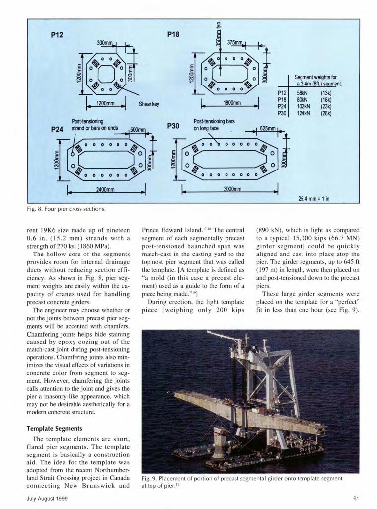
Prince Edward Island.'7· '
8 The central segment of each segmentally precast post-tensioned haunched span was match-cast in the casting yard to the topmost pier segment that was called the template. [A template is defined as "a mold (in this case a precast element) used as a guide to the form of a piece being made."'9
]
During erection, the light template piece [weighing only 200 kips
-I 25.4 mm = 1 in
(890 kN), which is light as compared to a typicall5,000 kips (66.7 MN) girder segment] could be quick ly aligned and cast into place atop the pier. The girder segments, up to 645 ft (197m) in length, were then placed on and post-tensioned down to the precast piers.
These large girder segments were placed on the template for a "perfect" fit in less than one hour (see Fig. 9).
Fig. 9. Placement of portion of precast segmental girder onto template segment at top of pier.18
61

3000mm
T12 2000mm T18 Bottom dimensions and .. ~··r~ t? chamfers are the same
,--~~ I , 900mm ~ as those for each
~gg;; \;,: /1 template's 150mm '1
corresponding pier 1200mm 1800mm
segment (T12 with P12, E levation Elevation T1 8 with P1B etc.)
shown in Figure B
§I II ·-= / .. ''.g;;;s. [:> Shear keys
il:iL. .,/· • • • • ' , ..E:Ii
r· o ·r ·: · c=J ·r Template Weights: • • 0 : 0 0
.r:::l.' ... .. ....... ~ ~'-... .. 0 . #/"''Q T12 56kN (1 3k)
Plan Plan T18 175kN (39k) T24 395kN (89k) TJO 748kN (168k)
T30 5000mm T24
4000mm varies"
\1 I? --~~ 1? E E § J~ "Template 'plate'
250mm ~ height varies as per
2400mm I 3000mm
·I desired cross slope.
Elevation Elevation
ii i!:::D·--.,...-· ........ . • . . . • ··· ··· .. ......--G
~I ~~· · · .. .. ·~~·e 1:c ) :! ): p ........ ~ ........ , . . . . . • /""-a:;~ . . . .. .. • ----·-C;!
Plan
Fig. 10. Four templ ate segments.
The tips of the cantilevers for these segments after placement were within 0.8 in. (20 mm) of their designed positions. This is a clear testimony to the excellence of a construction method using small precast template segments.
Although the precast substructure system presented here is on a much smaller scale than the Northumberland Strait Crossing project, the erection time can be greatly reduced and the geometry control improved by matchcasting the cap to the template. The lighter template piece can be properly aligned in the field to the proper deck cross-slope and set with a cast-inplace joint more quickly than the heavier, awkward-shaped cap.
Fig. 10 shows the four template sizes and their weights. Each template size corresponds to one of the four pier segments . The small size of the template allows it to be not only a construction aid, but also an artistic opportunity. An interesting shape could easily be accommodated in this small segment. A flared template provides strong visual integra-
62
Plan
tion between the pier and cap. The flared template also decreases the bending moment at the critical section in the cap for less required cap reinforcement.
Bent Caps
To keep the weight of the cap low so that large, single- seg ment caps could be constructed, the structural function of the cap was examined. The flow of forces for the solid cap shows areas where the concrete is not needed structurally - in the center of the stem and in the bottom outer corners of the ledge. Removing this unnecessary material from the inverted-T cap reduces both the cap dead load and the amount of required cap reinforcement.
The precast cap elements may be longitudinally pretensioned , posttensioned or a combination of both (see Fig. 11a). The web walls of the inverted-T stem [14 in. (350 mm) in the cantilevered portions and 15 in. (375 mrn) at the cap-column connection] provide adequate cover for the
25.4 mm= 1 in
anchorage zone and shear reinforcement with sufficient room for concrete placement and consolidation. Fig. 11 b shows details of a fully pretensioned precast cap.
For the fully pretensioned option, each wall can accommodate four columns of 0.5 in. (12.7 mm) diameter pretensioning strands on 2 in. (50 mm) centers, a 2 in . (50 mm) duct for vertical column post-tensioning bars with proper coupling sheaths, and interior cover. An alternative design for the pretens ioned cap would be to use 0.6 in . ( 15 .2 mm) diameter strands . The number of strands could be reduced with a probable reduction in plant labor costs and a slight increase in the eccentricity of the pres tress force.
The cap walls can also accommodate 4 in . (1 00 mm) ducts for 19K6 multi strand longitudinal tendons instead of pretensioning strand with the column post-tensioning bars located up to 2 in. (50 mm) closer to the outside cover of the stem. A combination of cap longitudinal pretensioning and
PCI JOURNAL

_ Pretensioning option -.:'7'-·
rt Post-tensioning opti~
lenath varies
! fS]j_ [~~-: ----- -------- --- -- ] ==-~ ·-·-·
-, -..
Pretensioning strands Plan Post-tensioning duct
A-A
Fig. 11 a. Precast cap detai ls.
post-tensioning may also be accommodated using the two outer columns of pretensioning and a maximum of a 4 in. (100 mm) duct (required for a 19K6 multi-strand tendon) for posttensioning.
Fig. 12 shows portions of the cross section at the cap-column connection for a cap with both pretensioning and post-tensioning. The pretensioning and post-tensioning combination for cap longitudinal reinforcement is typical for frame bents.
While the center of the cap stem would be hollow, solid portions are required at the ends for cap anchorage zones when longitudinal post-tensioning is used (see Fig. lla). Anchorage zones are also required above the column for the column reinforcement not anchored in the webs of the stem.
BENT CONFIGURATIONS The four pier sizes, four correspond
ing templates and the single depth but variab le length cap section can be combined in numerous ways to make up a wide range of substructure units extending from single-column bents to straddle bents and frame bents (see
July-August 1999
PT strand duct
PT bar duct with room for coupler at base of template
Shear Stirrups & Hanger Reinforcement
Pretensioning
350mm
Ledge Reinforcement
r 1i: 'l l., ....
B A2<j.--J Elevation
B-B
A1 - A1
.J~ecess for PT operations
_ _.,,.-"'
B
<t I
I •
A2 - A2
Precast Template
25.4 mm = 1 in
Column PT Bar Anchorage
Bursting Reinforcement
375mm
PT Bar Coupler
PT Anchorage for Erection
Column PT Bar in Duct
25.4 mm = 1 in
Fig. 11 b. Cross sections of cap and template for fu ll y pretensioned cap.
63
350mm ~, 375mm ~,
20mm 20mm 30mm
.... : : ::: :::::::::~:::::::::::::-· = :~:::::::::::::::::::::::::::::::::~:: .. ~~~~ i= l 94mm
50mm
E E
~ E E ~ ~
~ ~ E ~ E E ~~~ E E
~~ E E E E ..., 0 ;::: 8 o- E E E "' ..... ........, <D 00
~ u:; ..., MN"' "'"'
,_
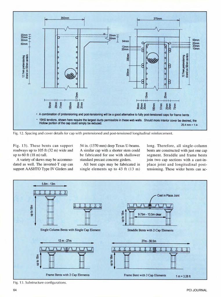
• A combination of pretensioning and post-tensioning will be a good alternative to fully post-tensioned caps for frame bents
• 19K6 tendons, shown here require the largest ducts permissible in these web walls. Should more interior cover be desired, the Hollow portion of the cap could simply be reduced.
25.4 mm = 1 in
Fig. 12 . Spacing and cover details for cap w ith pretensioned and post-tens ioned longitudinal reinforcement.
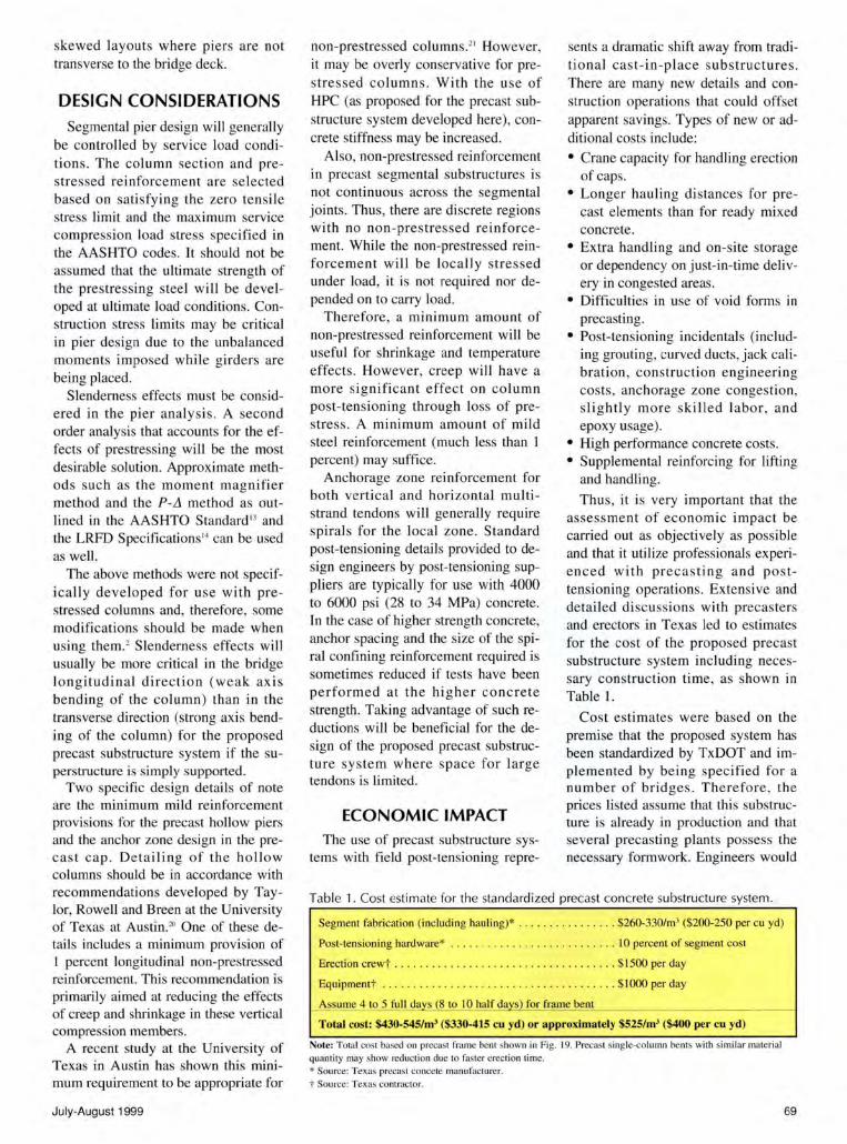
Fig. 13). These bents can support roadways up to 105 ft (32m) wide and up to 60ft (18m) tall.
A variety of skews may be accommodated as well. The inverted-T cap can support AASHTO Type IV Girders and
5.8m - 13m
54 in. (1370 mrn) deep Texas U-beams. A similar cap with a shorter stem could be fabricated for use with shallower standard precast concrete girders.
All bent caps may be fabricated in single elements up to 43 ft ( 13 m)
long. Therefore, all single-column bents are constructed with just one cap segment. Straddle and frame bents join two cap sections with a cast-inplace joint and longitudinal posttensioning. These wider bents can ac-
Cast in Place Joint
9. 75m - 13.5m clear
c. :::>
Single Colunm Bents with Single Cap Element Straddle Bents with 2 Cap Elements
13m -27m 27m-30.5m
Frame Bents with 2 Cap Elements Frame Bent with 3 Cap Elements 1 m = 3.28 ft
Fig. 13. Substructure configurat ions.
64 PCI JOURNAL

commodate caps up to 88 ft (27 m) in length with just two cap segments [two 43 ft (13 m) segments with a 30 in. (800 mm) cast-in-place joint].
Wider bents can be accommodated with two piers and two long segments and one shorter cap segment matchcast to a long segment. Details of fabrication and erection for this scheme are described in Ref. 2. Alternatively, three piers and three caps could be utilized.
The pier segment chosen for a project will vary depending on project constraints. Roadway width, span lengths, road curvature, pier height and bent skews will all affect the pier size requirement. Other factors affecting the choice of pier size will be concrete strength and type of column reinforcement chosen.
For instance, a 60 ft ( 18 m) high single-column pier supporting a 46 ft (14 m) wide roadway could be constructed of P30 segments (see Fig. 8) with a concrete strength of 8000 psi (56 MPa) or P24 segments with a 11,000 psi (76 MPa) concrete. This choice is possible because the controlling factor for the pier design is the maximum compression stress resulting from the column post-tensioning necessary to prevent tension across the segmental joints under biaxial bending in the service limit state.
With the frame bents, the pier segment size should initially be chosen based on structural requirements . In many cases, the smallest column section may suffice for column loads. However, with longer bents, a larger column section and, therefore, larger template section will reduce the critical bending moment and shear forces in the cap.
The designer must balance issues of economics and constructability when choosing between using larger column sections or more cap reinforcement. For aesthetic reasons as well, the designer may choose to use larger column sections for a long frame bent. Slender columns under a wide superstructure may appear visually weak and unsafe.
FABRICATION SEQUENCE The fabrication sequence for the
precast column segments is outlined in Fig. 14. The column segments are
July-August 1999
1) Previously cast bulkhead Segment A is aligned and surveyed.
2) Bond-breaking substance is applied to top face of segment.
3) Outer form for Segment B is positioned and surveyed.
4) Reinforcing cage and central void form are inserted in Segment B form .
5) Seg men! B concrete is cast.
r--
B ~
- A ~ 6 6
....---6) After adequate curing, forms are removed, the
relation between Segment A and Segment B is surveyed, and Segment B is moved into position as bulkhead segment for casting of Segment C.
B 7) Segment A is removed for storage, Segment B is
aligned and surveyed, and the entire process is repeated .
Fig. 14 . Short- line match-casting procedure for precast pier segments.
match-cast in their vertical position . Vertical casting has many advantages. Formed surfaces will make up all finally visible faces of the column. The concrete can be better consolidated around the ducts and the inner core form. Handling will be easier as the segments will be stored, hauled and erected in the same orientation as they were cast.
Because of the advantages of vertical casting, the "short-line" method is used to cast the segments. In this method , the casting equipment is never more than two segments high. Minimizing this height allows for easier assembly and lifting as well as use of equipment in existing precasting plants.
The template segments are to be cast individually. The top portion of the template is essentially a quadrilateral plate . The top surface can be screeded to vary ing standard vertical angles to provide the necessary crossslope for the cap. The overall plate height varies depending on the template size.
This variation according to template size allows each template to readily provide up to a 3 percent cross-slope for the cap. Required cross-slopes greater than 3 percent can be accommodated by developing other template design s or by using the 3 percent cross-s lope in the template and then by varying girder bearing seat elevations for additional cross-slope.
65

Cage Steel
\ Column Post-tensioning Ducts
i l ., 1' I
........--1 I! ~1 11 •i ii li L~ge~ ~~~------~nr--------~==~'4· ~~-~- ·~--~~~~~---~- ·t·~· =s~------~nr--------Tr~
PT Strand .lh-~: I i I! Jj J l KMatch cast Duct _.---- . jlj_ jj II ! ! JOint
/ PT Bar , ; ~A g -\} .
I \ / I \ Duct '1-llH-; 1
7: '1'+-tt;-
71,H, '++~n Precast Template J l
{ \ I
Support for ledge formwork j ' Adjustable template supports A for cap cross slope
Stage 1. Match cast ledge of cap to precast template
Pretensioning Bulkhead
~ ::::·,;,, ~ .... of""" "' """"' "" "'' l j !
Ledge cast in Step 1
Stage 2. Place ledges in pretensioning bed, form stems, pretension and cast • Shown in Figure 15b
Fig. lSa. Two-stage match-casting of precast, pretensioned inverted-T caps.
Ducts for post-tensioning bars must be cast into the template segment. A pattern sheet (metal plate with duct locations drilled through) could be fabri cated to ensure proper location and alignment of ducts between the template and column segments. Approxi mately four additional ducts of 1.5 in . ( 40 mm) diameter must be cast into the template for placement of a flowable high strength grout to completely fill the joint between the top pier segment and the template segment.
Fabrication of the caps will be much more involved than fabrication of the column segments. There are a number of workable schemes for fabricating the caps with the necessary match-cast joint between the bottom of the cap and the top of the template segment. Some fabrication options are better suited for pretensioning, while others are better suited for post-tensioning.
For pretensioning, a fabrication system for the caps that can be easi ly adopted by existi ng pretensioning plants was developed and is presented here. This system involves casting the cap in two-stages. In the fi rst stage, the ledge of the cap would be match-
66
Cage steel
Ledge cast in Step 1
~- : K Fo~wOO< fo< """'
.
~ l
Match-cast joint v-- Precast template
.L.J
r-- Adjustable supports for cap cross slope 'f
Fig. lSb. Cross section through cap and template during Stage I from
Section A-A*
cast to the previously cast template . This operation could be done with the template supported from the ground and the ledge form supported above (Stage L in Fig. 15a and Fig. l 5b). Web reinforcement would extend above the ledge.
• From Figure 15a Fig. lSa.
The casting operations wou ld require concrete placement not more than 12ft (3.6 m) above ground level. Once the ledge is cast and the concrete cured, the ledge would be transported to an existing pretensioning bed (Stage 2 in Fig. 15a). With a
PCI JOURNAL

number of ledges in the bed, pretensioning strands would be placed and forms for the inverted-T stems set.
Post-tensioning ducts for the column and, if required, for the cap would be aligned and the concrete placed. For most of the single cap segments, pretensioning will suffice (no post-tensioning will be required) for the cap's longitudinal reinforcement. Only in cases with long caps that need to be stage tensioned, or in the case of frame and straddle bents·, will post-tensioning be required.
The two-staged casting of the cap for this pretensioning scheme eliminates the need for self-stressing forms (forms with ends that essentially act as bulkheads) that would be 6.5 to 13 ft (2 to 4 m) above ground level. Staged casting allows the precaster to use existing pretensioning beds and bulkheads. Staged casting also eases concrete placement, avoiding problems due to trapped air under the ledge that could occur with a single, closed form.
With the staged casting, concrete shear keys, if needed, may be set into the ledge for shear transfer in the concrete for the fmal structure. Web hanger reinforcement for shear will also need to extend upward or be mechanically spliced at this location. Fig. 15a shows a scheme where the stirrups required for the cap would be cast into the ledge. This detail provides unspliced stirrups
and a cage with which to lift the ledge into a pretensioning bed.
In single-stage casting, vibration of the ledge down through the walls of the stem would be extremely difficult with pretensioning strand running throughout. One possible solution would be to vibrate the ledges through the open top surfaces of the ledges, allow the concrete to develop an initial set for 30 to 45 minutes and then place the web concrete.
Another possible method of cap construction would be to insert the template segment in an opening below grade and match-cast the cap to the template while the cap is supported at grade level. Casting could again be staged with the ledge being cast first and then placed in a pretensioning bed . Self-stressing forms could be used for both of the previously mentioned fabrication methods if singlestage casting is desired.
Fabrication of precast caps that will be entirely post-tensioned can be performed in a precasting plant or in a temporary precasting yard. Similar schemes as presented previously may be employed to fabricate the match-cast joint between the template and the cap.
ERECTION SEQUENCE
After the drilled shaft, spread footings or pile cap foundations at the
bridge site are completed, precast substructure elements can be hauled to the site for erection . The erection sequence for a single column bent is shown in Fig. 16.
The first segment is placed and aligned on adjustable supports on top of the footing. Where desirable for geometric flexibility with standard height segments, the footing could be designed to have a recess in which to place the first segment. With a recess, however, the overall footing (or pile cap) depth may be increased. A common adjustable support system would be a steel frame that can be adjusted with screw threads or shims.
Once aligned, ducts are connected and the post-tensioning bars are threaded into anchors previously cast into the foundation. The bottom segment is then "locked" in position with a cast-in-place joint. This first joint should be a concrete of similar quality to the pier segments. This joint may vary in height from 12 to 24 in. (300 to 600 mrn) depending on the required height of the pier.
A number of first segments may be placed and aligned for a project before they are "locked" into position with these cast-in-place joints. Due to the relatively small amount of concrete needed to set each segment [less than 3 cu yd (2.3 m3) for the largest segment], placing concrete for more than
Match-cast
Post-tensioning of cap to column all from
Precast Template
Adj ustable Supports
(Cap lifted by I or 2 cranes as per weight)
"Looped" PT Strand
Coupled Post Tensioning Bars
Fig. 16. Erection sequence for single-co lumn bent with single cap element.
July-August 1999 67

one column at a time will be more economical and less time-consuming in terms of disruptions to the site due to field concreting.
With the first segment set, the next pier segment can be lifted into place above the first segment. Before the segment is lowered, post-tensioning bars are coupled and epoxy is placed on the faces of adjoining segments. The segment is then lowered into position with the match-cast joints with aligning shear keys allowing for rapid placement. Post-tensioning can then be stressed if needed to provide the required pressure across the joint for even-setting of the epoxy. If placing a loose segment on top of the newly joined segments would apply adequate pressure across the epoxy joint, labor
(a)
(b)
costs could be reduced considerably and construction speed increased.
Additional column segments are placed similarly. With the final pier segment in position, the template segment can then be placed. The template is set on adjustable supports, posttensioning ducts are spliced and the segment is aligned to provide the proper cross-slope for the match-cast cap. This joint can be very small [3 to 4 in. (75 to 100 mm)] and will be filled with a durable high strength epoxy grout. Grouting the joint will typically be more economical than placing such a small amount of concrete at heights up to 60ft (18m).
This second designated geometry control joint under the template serves two purposes. First, this geometry
Fig. 17. Computer-aided renderings of single-column bent using proposed precast substructure system.
68
control joint allows for accurate cap placement. Second, any unforeseen out-of-straightness resulting from initial setting and subsequent placement of column segments can be corrected at this joint.
With the template in place, the cap can be rapidly positioned into its match-cast alignment on the epoxy joint and post-tensioned down to the column. No special alignment procedures are necessary for this heavy element. It is si mply set in place, selfaligned due to the match-cast shear keys, and is vertically post-tensioned to the pier. Again, all post-tensioning operations can be carried out from above.
The recess in the cap for the vertical post-tensioning anchor plates can then be filled with a highly durable concrete. Any required longitudinal posttensioning of the cap is performed next. In some cases, staged post-tensioning of the cap may be necessary. This post-tensioni ng would be sequenced in accordance with placement of the superstructure.
Pier erection for frame bents is the same as that for single-column bents. A match-cast cap segment is vertically post-tensioned to each pier. The remaining joint between the cap segments would then be formed, posttensioning ducts spliced, and non-prestressed reinforcement tied.
Cast-in-place concrete is then placed in the joint, cured, and the entire cap post-tensioned to provide positive moment reinforcement at the midspan of the bent. Again, staged post-tensioning may be required during placement of the superstructure. As mentioned previously, bents wider than 88 ft (27 m) may be designed using additional match-cast cap segments. Erection for this option is described in detail in Ref. 2.
For the frame bent caps and the single-column bent caps requiring posttensioning, an additional cast-in-place cover could be added to the ends of the cap to cover the post-tensioned anchor plates. This addition can be attractively chamfered as shown in Fig. 17 . A chamfered end minimizes the visual disruption to the profile of the bridge that blunt bent cap ends often create. The chamfers will also integrate the cap more attractively with
PCI JOURNAL
skewed layouts where piers are not transverse to the bridge deck.
DESIGN CONSIDERATIONS
Segmental pier design will generally be controlled by service load conditions . The column section and prestressed reinforcement are selected based on satisfying the zero tensile stress limit and the maximum service compression load stress specified in the AASHTO codes. It should not be assumed that the ultimate strength of the prestressing steel wi ll be developed at ultimate load conditions. Construction stress limits may be critical in pier design due to the unbalanced moments imposed while girders are being placed.
Slenderness effects must be considered in the pier analysis. A second order analysis that accounts for the effects of prestressing will be the most desirable solution. Approximate methods such as the moment magnifier method and the P-11 method as outlined in the AASHTO Standard'' and the LRFD Specifications '• can be used as well.
The above methods were not specifically developed for use with prestressed columns and, therefore, some modifications should be made when using them.2 Slenderness effects will usually be more critical in the bridge longitudinal direction (weak axis bending of the column) than in the transverse direction (strong axis bending of the column) for the proposed precast substructure system if the superstructure is simply supported.
Two specific design detail s of note are the minimum mild reinforcement provisions for the precast hollow piers and the anchor zone design in the precast cap. Detailing of the hollow columns should be in accordance with recommendations developed by Taylor, Rowell and Breen at the University of Texas at Austin.20 One of these detail s includes a minimum provision of 1 percent longitudinal non-prestressed reinforcement. This recommendation is primarily aimed at reducing the effects of creep and shrinkage in these vertical compression members.
A recent study at the University of Texas in Austin has shown this minimum requirement to be appropriate for
July-August 1999
non-prestressed columns.2' However,
it may be overly conservative for prestressed column s. With the use of HPC (as proposed for the precast substructure system developed here), concrete stiffness may be increased.
Also, non-prestressed reinforcement in precast segmental substructures is not continuous across the segmental joints. Thus, there are discrete regions with no non-prestressed reinforcement. While the non-prestressed reinforcement will be locally s tressed under load, it is not required nor depended on to carry load.
Therefore, a minimum amount of non-prestressed reinforcement will be useful for shrinkage and temperature effects. However, creep will have a more significant effect on column post-tensioning through loss of prestress . A minimum amount of mild steel reinforcement (much less than I percent) may suffice.
Anchorage zone reinforcement for both vertical and horizontal multistrand tendons will generally require spirals for the local zone. Standard post-tensioning details provided to design engineers by post-tensioning suppliers are typically for use with 4000 to 6000 psi (28 to 34 MPa) concrete. In the case of higher strength concrete, anchor spacing and the size of the spiral confining reinforcement required is sometimes reduced if tests have been performed at the higher concrete strength. Taking advantage of such reductions will be beneficial for the design of the proposed precast substructure system where space fo r large tendons is limited.
ECONOMIC IMPACT The use of precast substructure sys
tems with field post-tensioning repre-
sents a dramatic shift away from traditional cast-in-place substructures. There are many new details and construction operations that could offset apparent savings. Types of new or additional costs include:
• Crane capacity for handling erection of caps.
• Longer hauling distances for precast elements than for ready mixed concrete.
• Extra handling and on-site storage or dependency on just-in-time delivery in congested areas.
• Difficulties in use of void forms in precasting.
• Post-tensioning incidentals (including grouting, curved ducts, jack calibration , construction engineering costs, anchorage zone congestion, slightly more skilled labor, and epoxy usage).
• High performance concrete costs. • Supplemental reinforcing for lifting
and handling.
Thus, it is very important that the assessment of economic impact be carried out as objectively as possible and that it utilize professionals experienced with precasting and posttensioning operations. Extensive and detailed discuss ions with precasters and erectors in Texas led to estimates for the cost of the proposed precast substructure system including necessary construction time, as shown in Table 1.
Cost estimates were based on the premise that the proposed system has been standardized by TxDOT and implemented by being specified for a number of bridges . Therefore , the prices listed assume that this substructure is already in production and that several precasting plants possess the necessary formwork . Engineers would
Table 1. Cost estimate for the standardized precast concrete substructure system.
Segment fabrication (including hauling)* .. . . . .. . . . . . . .. . $260-330/m3 ($200-250 per cu yd)
Post-tensioning hardware* ...
Erection crewt ...
Equipmentt
...... .... . . .. . . .. . I 0 percent of segment cost
...... . . . .. . . .. $ 1500 per day
....... . .... . .. . ........ $ 1000 per day
Assume 4 to 5 full days (8 to I 0 half days) for frame bent
Total cost: $430-545/m3 ($330-415 cu yd) or a pproximately $525/m3 ($400 per cu yd)
Note: Total cost based on precast frame bent shown in Fig. 19. Precast single-column bents with similar material quantity may show reduction due to faster erection time.
* Source: Texas precast concete manufacturer.
t So urce: Texas contractor.
69

be able to specify standard precast piers just as they now specify standard 1-beams or box beams.
The estimate of construction time given in Table 1 was made by the authors based on observations of recent field experiences in Texas. The erection of five si ngle precast colu mns (the equivalent of one five -column cast-in-place bent) for the Louetta Road Overpass in Houston , Texas , (see Fig. 3) required roughly 10 days in the field. A two-column precast frame bent was then estimated as requiring 4 to 5 full days (8 to lO half days) . No cost benefits are included for the substantially reduced field construction time with possible savings in traffic control and benefits in early completion of the project.
Fig. 18 gives a comparison between the estimated proposed precast substructure cost and the current average bid prices in Texas for cast-in-place substructures with rectangular caps and with inverted-T caps. The precast substructure system with its invertedT cap would be most competitive with
• Texas State average bid prices from 1996 .. Cost estimate as outlined in Table 1
Fig. 18. Comparison of substructu re costs.
70
the cast-in-place inverted-T alternative and has both aesthetic and life-cycle cost advantages. Although the cost per cubic yard for the precast system is higher, the overall cost of a bent will be lower than that of a conventional inverted-T system in many cases.
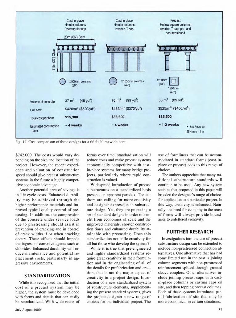
A comparison of material quantities, estimated cost and estimated construction time for the three types of construction shown in Fig. 18 is given for a hypothetical multi-column bent in Fig. 19. Even without including the potentially significant cost benefits of faster on-site construction times , the proposed precast system is highly competitive with the inverted-T design. Neither the proposed precast system nor the presently widely used inverted-T cap system is competitive in terms of material quantities or substructure costs with the traditional rectangular cap system.
The precast system could be justified as a replacement for the rectangular cap system based on reduced construction time or improved aesthetics and/or vertical height factors as are
Cast-in-place Circular Columns Rectangular cap
$420/m3 ($320/yd3)*
Cast-in-place Circular columns Inverted T cap
$485/m3 ($370/yd3)*
Precast Hollow columns Inverted T cap, pre- and post-tensioned
$525/m3 ($400/yd3)**
now used to justify use of the inverted-T cap system. The precast system could also be justified where bridge costs are a small portion of a large highway project , and the increases in substructure cost have a minimal effect on overall project cost.
Recall that for the Edison Bridge mentioned previously, the substructure bid made up roughly 7.5 percent of the total bridge cost. In Texas, the substructure typically accounts for roughly 30 percent of a total bridge cost. Therefore, a 30 percent increase in substructure cost would be a 9 percent increase in total bridge cost. Increases in total highway project cost would be an even smaller percentage.
For the proposed substructure system, efficiency in substructure design was considered to be the minimization of wasted material, non-productive labor, and construction time in meeting the user's needs within the project constraints. Comparing the precast system with the inverted-T cap system, the material and labor savings as reflected in volume of concrete are in the 10 percent range. This is offset by an 8 percent increase in estimated unit cost of concrete, reflecting the extra operations involved in handling and connecting the precast units.
Thus, significant efficiencies would only be seen from minimization of construction time. This time reduction wou ld present savi ngs on projects where such shorter construction times would result in reduction of user delays, improved safety , and lowered traffic rerouting costs. Aesthetic improvements would have to be justified on a project-to-project basis.
The value of a day of construction time saved for a recent urban highway project in Texas was estimated at $53,000. 22 Clearly, the value of construction speed in certain locations will far outweigh the construction cost differences of different substructure systems.
For example, as shown in Fig. 19, while each precast substructure unit may cost $20,000 more than a cast-inplace multi-column bent with a rectangular bent cap, a project construction time savings of two weeks in the congested urban site mentioned previously would equate to a savings of
PCI JOURNAL
Cast-in-place circular columns Rectangular cap
20m 166') Bent
Cast-in-place circular columns Inverted-T cap
<I>900mm columns (36")
<I>1050mm columns (42")
Volume of concrete 37 m3 (48 yd3) 76 m3 (99 yd3
)
Unit cost*
Total cost per bent
$420/m3 ($320/yd3)
$15,300
$485/m3 ($370/yd3)
$36,600
Estimated construction - 4 weeks -4weeks
time
Fig. 19. Cost comparison of three designs for a 66ft (20m) wide bent.
$742,000. The costs would vary depending on the size and location of the project. However, the recent experience and valuation of construction speed should give precast substructure systems in the future a highly competitive economic advantage.
Another potential area of savings is in life-cycle costs. Enhanced durability may be achieved through the higher performance materials and improved typical quality control of precasti ng. In addition, the compression of the co ncrete under service loads due to prestressing should assist in prevention of cracking and in control of crack widths if or when cracking occurs. These effects should impede the ingress of corrosive agents such as chlorides. Enhanced durability will reduce maintenance and potential replacement costs , particularly in aggressive environments.
STANDARDIZATION While it is recognized that the initial
cost of a precast system may be higher, the system must be developed with forms and details that can easily be standardized. With wide reuse of
July-August 1999
forms over time, standardization will reduce costs and make precast systems economically competitive with castin-place systems for many bridge projects, particularly where rapid construction is valued.
Widespread introduction of precast substructures on a standardized basis presents an apparent paradox. The authors are calling for more creativity and designer expression in substructure design. Yet, they are proposing a set of standard designs in order to benefit from economies of scale and the improved materials, shorter construction times and enhanced durability attainable with precasting. Does this standardization not stifle creativity for all but those who develop the system?
While it is true that pre-engineered and highly standardized systems require great creativity in their formulation and in the engineering of all of the details for prefabrication and erection , that is not the major aspect of creativity in a project design. Introduction of a new standardized system of substructure elements, supplementing the present standard systems, gives the project designer a new range of choices for the individual project. The
Precast Hollow square columns Inverted T cap, pre- and
post-tensioned
1200mm I 0 I (48") .
1200mm (48")
68m3 (89 yd3)
$525/m3 ($400/yd3)
$35,500
-1-2 weeks * See Figure 18
25.4 mm = 1 in
use of formliners that can be accommodated in standard forms (cast-inplace or precast) adds to this range of choices.
The authors appreciate that many traditional substructure standards will continue to be used. Any new system such as that proposed in this paper will broaden the designer's range of choices for application to a particular project. In this way, creativity is enhanced. Naturally, the need for economy in the reuse of forms will always provide boundaries to unfettered creativity.
FURTHER RESEARCH Investigations into the use of precast
substructure design can be extended to include non-prestressed connection alternatives. One alternative that has had some limited use in the past is joining column segments with non-prestressed reinforcement spliced through grouted sleeve couplers. Other alternatives include joining precast caps with castin-place columns or casting caps on site, and then topping precast columns. Each of these systems introduces partial fabrication off site that may be more economical in certain situations.
71

Potential applications of precast substructure systems should be examined for seismic regions. The introduction of post-tensioning in the substructure has the potential to reduce residual displacements and improve joint shear performance.23
•24
·25
Further study of the economic impact of more rapid on-site construction would benefit the future implementation of such a substructure system. While material and labor costs are easily estimated and over time become more accurate, the advantages of avoiding traffic delays and making new highways available to the public faster are less quantifiable but may in fact have a more profound impact on the economics of precast substructure systems.
Recent attempts to quantify motorist inconvenience exemplify the importance of speed of construction. Different ways in which faster construction can benefit a community should be emphasized, observed and recorded.
The economic advantages of precasting year-round in harsh climates where the construction season is short should also be further examined. Investigations into minimum mild steel reinforcement requirements for steel prestressed columns should be made.
CONCLUDING REMARKS Substructure design provides an op
portunity for creative design with short- and moderate-span bridge systems. New technologies and new materials can be applied with attractive and economical results. Substructures can be constructed using methods of precasting, casting in place or a combination of the two. This paper has presented a precast substructure system for standardization. A geometrically similar system may be cast-in-
72
place or be a combination of both precast and cast-in-place elements.
The proposed precast substructure system is a versatile system that can be used for a wide variety of bridge widths and heights. This system can be used with standard precast girder superstructure systems and offers a new alternative to substructure design that can increase construction speed, thereby reducing costs associated with traffic delays and rerouting.
The precast system of match-casting with epoxy joints has provided excellent durability for structures in the past. The combination of precasting and the use of high performance concrete results in more durable and attractive construction. This proposed system is not a universal solution. Replacing a multi-column bent that has a rectangular bent cap with a single-column pier will generally increase costs. If the substructure is concealed from public view and does not interfere with traffic, and if construction speed is not a factor, the proposed system may be unnecessary or undesirable.
Precast substructures have been used successfully in the past. However, there is limited field information on their behavior and performance. More importantly, there is limited contractor experience with this form of construction. Perhaps the highest hurdle to overcome with developing new precast substructure systems is the many unfounded negative beliefs about such systems held by "prisoners of the familiar." Through attention to industry concerns and knowledge of past successes and failures, new substructures that are functional, economical and attractive can be designed and built.
The proposed system will be most useful at first for large, highly repetitive projects in highly visible locations
where construction efficiency (speed of construction) and final appearance are particularly important. An initial investment in forms for a large project will lead to future savings when the forms are reused for similar or smaller projects.
Over time and with high reuse of forms, new standard shapes for substructures may be developed to provide designers with even more alternatives for attractive and rapidly constructed substructures. With careful implementation of this recent trend in substructure design, the advantages of precast segmental substructure systems will become evident.
ACKNOWLEDGMENTS The ideas expressed in this paper
are those of the authors and not necessarily those of the sponsors. Development of this precast substructure system included extensive contributions from the research team, designers, precasters, form manufacturers and contractors.
The significant contributions of the TxDOT project directors Norman Friedman and Dean Van Landuyt are gratefully acknowledged. Special recognition is also given to Thomas J. D ' Arcy as a representative of the Texas Precast Manufacturers Association and to William F. Daily of Hamilton Form Company, Inc.
The authors also acknowledge the insightful contributions of Professors Andrew Vernooy and Daniel Leary of the School of Architecture at the University of Texas at Austin as well as graduate research assistants Carl Holliday and Steven Ratchye.
Finally, the authors wish to thank the PCI JOURNAL reviewers of this paper for their constructive comments and helpful suggestions.
PCI JOURNAL

REFERENCES
1. West, J. S., "Durability Design of Post-Tensioned Bridge Substructures," Ph.D. Thesis, The University of Texas at Austin, Austin, TX, 1999.
2. Billington, S. L., Barnes, R. W., and Breen, J. E., "A Precast Substructure Design for Standard Bridge Systems," Research Report 1410-2F, Center for Transportation Research, The University of Texas at Austin, Austin, TX, 1999.
3. Poston, R. W., Diaz, M., and Breen, J. E., "Design Trends for Concrete Bridge Piers," ACI Journal, V. 83, No. 1, JanuaryFebruary 1986, pp. 14-20.
4. Freyermuth, C. L., "Building Better Bridges: Concrete vs. Steel: Sizing up Segmentals," Civil Engineering, V. 62, No.7, July 1992, pp. 66-69. (See also Ref. 2 under Serviceability of Concrete Bridges in Appendix A.)
5. Muller, J. M., and Barker, J. M., "Design and Construction of Linn Cove Viaduct," PCI JOURNAL, V. 30, No. 5, September-October 1985, pp. 38-53.
6. Podolny, W., Jr., and Muller, J. M., Construction and Design of Prestressed Concrete Segmental Bridges, John Wiley & Sons, New York, NY, 1982, pp. 543-545.
7. Wolf, L. M., and Friedman, N. K., "Redfish Bay and Morris & Cummings Cut: Innovations on Bridge Construction and Durability," Technical Quarterly, V. 9, No.2, Texas Department of Transportation, Austin, TX, October 1994, pp. 1-3.
8. Muon, W. D., "Precast Cofferdams Speed Pier Construction," Highway & Heavy Construction, V. 130, No. 10, October
1987' pp. 58-60. 9. "Torridge Bridge Combines Aesthetic Excellence with Con
struction Economy," Concrete Construction, V. 34, No. 5, May 1989, pp. 447-452.
10. "Engineering Initiative Helps Solve Beach Problem in Port Elizabeth," Die Siviele Ingenieur in Suid-Afrika, V. 33, No. 6, June 1991, pp. 197-199.
11. Ingerslev, L. C. F., "Precast Concrete for Bahrain Causeway," Concrete International, V. 11, No. 12, December 1989, pp. 15-20.
12. "Development of Precast Bridge Substructures," Prepared for the Florida Department of Transportation by LoBuono, Armstrong & Associates, HDR Engineering, Inc., and Morales and Shumer Engineers, Inc., May 1996.
July-August 1999
13. AASHTO, Standard Specifications for Highway Bridges, 16th Edition, American Association of State Highway and Transportation Officials, Washington, D.C., 1996.
14. AASHTO, AASHTO LRFD Bridge Design Specifications: Customary US Units, First Edition, American Association of State Highway and Transportation Officials, Washington, D.C., 1994.
15. AASHTO, Guide Specifications for Design and Construction of Segmental Concrete Bridges, 1994 Interim Specifications, American Association of State Highway and Transportation Officials, Washington, D.C., 1994.
16. Texas State Department of Highways and Public Transportation, Bridge Design Manual, First Edition, 1990.
17. Lester, B., and Tadros, G., "Northumberland Strait Crossing: Design Development of Precast Prestressed Bridge Structure," PCI JOURNAL, V. 40, No.5, September-October 1995, pp. 32-44.
18. Green, P., "Placing Spans at a Dire Strait," Engineering NewsRecord, September 16, 1996, pp. 26-30.
19. Merriam-Webster's Collegiate Dictionary, lOth Edition, Merriam-Webster, Inc., Springfield, MA, 1997.
20. Taylor, A. W., Rowell, R. B., and Breen, J. E., "Behavior of Thin-Walled Concrete Box Piers," ACI Structural Journal, V. 92, No. 3, May-June 1995, pp. 319-333.
21. Ziehl, P. H., "Minimum Mild Reinforcing Requirements for Concrete Columns," MS Thesis, The University of Texas at Austin, Austin, TX, 1997.
22. Kraker, J., "Contractor Wins Race to Finish Roadway with Days to Spare," Engineering News-Record, July 7, 1997, pp. 40-41.
23. Sritharan, S., Priestley, M. J. N., Seible, F., "Enhancing Seismic Performance of Bridge Cap Beam-to-Column Joints Using Prestressing," PCI JOURNAL, V. 44, No. 4, July-August 1999, pp. 74-91.
24. Ikeda, S., "Seismic Behavior of Reinforced Concrete Columns and Improvement by Vertical Prestressing," Challenges for Concrete in the Next Millennium, Proceedings of 13th PIP Congress, Amsterdam, May 1998, V. 2, pp. 879-884.
25. Kwan, W. P., and Billington, S. L., "Seismic Behavior of Precast Concrete Pier Cap-Beam-to-Column Joints," Proceedings of 8th Canadian Conference on Earthquake Engineering, Vancouver, British Columbia, Canada, June 1999.
73