Precast Concrete Pavements and Results of Accelerated...
19
Precast Concrete Pavements and Results of Accelerated Traffic Load Test 263 Precast Concrete Pavements and Results of Accelerated Traffic Load Test Erwin Kohler 1 Louw du Plessis 2 Peter J. Smith 3 John Harvey 4 Tom Pyle 5 ABSTRACT Precast slabs are considered an advantageous repair method for extending the service life of distressed concrete pavement. Benefits include long life expectancy of concrete slabs cast in factory-controlled conditions and the fact that fully cured precast slabs can potentially be put into use almost immediately upon installation, making them attractive for use on heavily traveled highways where work windows for full-depth repairs are short. These benefits can only be realized if precast slabs are constructed and installed with proper materials and adequate supervision, as there are many factors that can affect the structural and functional life of this increasingly popular type of pavement. This paper describes the evolution of precast concrete pavements in various countries and, in particular, in the United States. The design, construction, and installation of a particular system of precast slabs called Super-Slab™, is explained, and an overview of the results of accelerated load testing with a heavy vehicle simulator (HVS) recently performed in California are presented. The general conclusion is that the use of precast slabs for concrete pavement rehabilitation is being seriously evaluated in the United States at various levels, and it is being considered favorably by the Federal Highway Administration, American Association of State Highway and Transportation Officials, and various State and other highway agencies. There is also growing interest in this technology in other countries. The HVS results indicate that 1) the evaluated system of precast slabs can be safely opened to traffic in the ungrouted condition, so that the panels can be installed in consecutive nights rather than completing the entire installation at one time; 2) the life 1 Erwin Kohler, Ph.D., Project Scientist, University of California Pavement Research Center, CEE One Shields Avenue, Davis, CA 95616. [email protected] 2 Louw du Plessis, P.E., Research Group Leader, Accelerated Pavement Testing, CSIR-Built Environment, Meiring Naude Str, Pretoria, South Africa; [email protected] 3 Peter J. Smith, P.E., Vice President, Market Development and Product Engineering, The Fort Miller Co. Inc., Schuylerville, NY 12871; [email protected] 4 John Harvey, Ph.D., P.E., Associate Professor, Department of Civil and Environmental Engineering, University of California Davis; [email protected] 5 Tom Pyle, P.E., Chief, Office of Rigid Pavement Materials and Structural Concrete, Caltrans Division of Engineering Services, Sacramento, CA; [email protected]
-
Upload
vuongkhanh -
Category
Documents
-
view
219 -
download
0
Transcript of Precast Concrete Pavements and Results of Accelerated...
Precast Concrete Pavements and Results of Accelerated Traffic Load Test 263
Precast Concrete Pavements and Results of Accelerated Traffic Load Test
Erwin Kohler1 Louw du Plessis2 Peter J. Smith3 John Harvey4
Tom Pyle5
ABSTRACT
Precast slabs are considered an advantageous repair method for extending the service life of distressed concrete pavement. Benefits include long life expectancy of concrete slabs cast in factory-controlled conditions and the fact that fully cured precast slabs can potentially be put into use almost immediately upon installation, making them attractive for use on heavily traveled highways where work windows for full-depth repairs are short. These benefits can only be realized if precast slabs are constructed and installed with proper materials and adequate supervision, as there are many factors that can affect the structural and functional life of this increasingly popular type of pavement.
This paper describes the evolution of precast concrete pavements in various countries and, in particular, in the United States. The design, construction, and installation of a particular system of precast slabs called Super-Slab™, is explained, and an overview of the results of accelerated load testing with a heavy vehicle simulator (HVS) recently performed in California are presented. The general conclusion is that the use of precast slabs for concrete pavement rehabilitation is being seriously evaluated in the United States at various levels, and it is being considered favorably by the Federal Highway Administration, American Association of State Highway and Transportation Officials, and various State and other highway agencies. There is also growing interest in this technology in other countries.
The HVS results indicate that 1) the evaluated system of precast slabs can be safely opened to traffic in the ungrouted condition, so that the panels can be installed in consecutive nights rather than completing the entire installation at one time; 2) the life
1 Erwin Kohler, Ph.D., Project Scientist, University of California Pavement Research Center, CEE One Shields Avenue, Davis, CA 95616. [email protected] 2 Louw du Plessis, P.E., Research Group Leader, Accelerated Pavement Testing, CSIR-Built Environment, Meiring Naude Str, Pretoria, South Africa; [email protected] 3 Peter J. Smith, P.E., Vice President, Market Development and Product Engineering, The Fort Miller Co. Inc., Schuylerville, NY 12871; [email protected] 4 John Harvey, Ph.D., P.E., Associate Professor, Department of Civil and Environmental Engineering, University of California Davis; [email protected] 5 Tom Pyle, P.E., Chief, Office of Rigid Pavement Materials and Structural Concrete, Caltrans Division of Engineering Services, Sacramento, CA; [email protected]
264 Kohler, du Plessis, Smith, Harvey, and Pyle
of this system of precast slabs, when used as detailed for this test, is estimated to be between 142 and 242 million equivalent single-axle loads, equivalent to 25 to 37 years of service; and 3) the failure mechanism was no different than failure in cast-in-place jointed concrete pavements.
INTRODUCTION
Precast concrete has a proven track record as a durable high-performance product for bridge and commercial building construction (1), mostly as the result of a high level of quality control that can be achieved at a precast fabrication plant. For roadways, precast concrete also has an advantage in terms of how fast a facility can be opened or reopened to traffic since precast slabs are fully cured before they are shipped to the job site. Conventional cast-in-place pavement requires several days of curing time after the concrete is placed before it is strong enough to withstand traffic loads without risking premature consumption of fatigue life. Fast setting concrete used for patching and even hot-mixed asphalt requires some cure time before traffic loads may be applied.
Early opening to traffic reduces the costs to drivers that are directly attributable to congestion caused by construction activities. These user delay costs include increased fuel consumption, lost work time, and the social costs of increased air pollution. The savings in user delay costs achieved through restricting construction to only off-peak travel times (at night or over a weekend) can be significant (1).
The primary application of precast concrete pavement is on rehabilitation of high-traffic highways, ramps, intersections, and urban arteries. Rehabilitation needs range from intermittent slab replacement, which is a “patching” type repair, to full-scale continuous replacement on sometimes complex geometries, such as curved alignment encompassing varying widths and super-elevations. Full-depth replacement is especially necessary under many bridges where it is unacceptable to overlay existing pavement. Many intersections and ramps, to which there are no reasonable alternate routes, are too busy to permit any shutdowns during peak traffic hours. While some entire roadways may be shut down for “brief” periods of time for round-the clock work, many locations are restricted to 8-hour or even 5-hour closures. In all of these cases, high-quality materials and methods for installing them rapidly are desperately needed. Clearly, fully cured, high-performance precast slabs meet those needs (2).
Precast fabrication plants produce quality concrete mixtures, with low water-to-cementitious-materials ratio and a high level of uniformity. According to reference (1),
At most plants concrete batching and quality control is done on-site and the concrete is transported only a short distance from the batch plant to the forms, minimizing changes in concrete properties between the mixing and placing operations. Precast fabrication plants offer tremendous control over the curing operation. Precast concrete elements can be fabricated indoors, they can be wet-mat cured, steam cured, and curing can be maintained as long as necessary after casting. Problems that can affect cast-in-place pavement construction such as surface strength loss, “built-in” curling, inadequate air entrainment, and finishing, can all be eliminated with precast concrete.

Precast Concrete Pavements and Results of Accelerated Traffic Load Test 265
In the last 20 years or more the transportation industry has witnessed a near explosive growth in the use of precast products such as concrete pipe, bridge elements, highway barriers, curbs, retaining walls, and even traffic calming devices and street furniture. This can be attributed to the need for high-quality concrete structures, as discussed above, rapid installation, and the desire for special materials, colors, and craftsmanship best achieved in a precast facility. Increased use has also been facilitated by the evolution of high-capacity hauling and setting equipment and by the fact that most of the referenced products require minimal field preparation and are easily integrated to make up structures of greater magnitude. Bridge elements, for example, are typically set on two or four bearings and are typically joined together with cast-in-place concrete. Similarly, retaining walls are placed on narrow strip footings, typically requiring no additional connection, and highway barriers require careful grading of only a narrow supporting bed of material and are not connected at all. Pavement slabs, on the other hand, occupy large contact areas that must be graded or otherwise altered to provide full and uniform bedding support to the slabs. In addition, all slabs must be structurally interlocked to form the larger expanse of concrete pavement such that joint widths and surface uniformity fall within acceptable industry limits. While an examination of the literature reveals that successful techniques to meet all of these challenges have been slow to evolve, recent projects in the Netherlands, France, and particularly in the United States show real progress in meeting these requirements.
HISTORICAL EXPERIENCE WITH PRECAST CONCRETE PAVEMENT AROUND THE WORLD
A very limited amount of information existed even 10 years ago about precast concrete pavements. Apparently, one of the first precast projects occurred in the United States in 1960, when the South Dakota Highway Department developed a precast pavement with an asphaltic concrete overlay (3). The pavement consisted of pre-stressed panels, with a thickness of 11.4 cm (4.5 in.), placed on a sand bedding layer over a granular base. Once all the panels were set in place, they were overlaid with asphalt concrete. After initial trials, a 300-m (1,000-ft) section was constructed on US highway 14, which is believed to still be in place (4).
Precast concrete pavements were used in the early 1970s in Japan in container yards and airports, but it was not until 1991 that researchers examined the use of precast concrete panels for roadway pavements. One of the first test pavements consisted of panels of three different sizes: 1 m by 2 m (3.3 ft by 6.6 ft), 2 m x 2 m (6.6 ft by 6.6 ft), and 3 m by 2 m (9.8 ft by 6.6 ft). According to Merritt et al. (4), all of the panels were approximately 15 cm (5.9 in.) thick. The panels were placed on stabilized subbase and were not prestressed either transversely or longitudinally. In addition, there were no load transfer devices at the joints between the panels. Another project in Japan investigated a method for prestressing the joints of precast concrete pavements. No information was found regarding long-term performance, but slabs and joints behaved adequately for at least the first 13 years (see Table 1). The use of precast concrete pavement increased in Japan when a special load transfer system, called the “horn joint,” was developed. There are a large number of tunnels in the Japanese highway network, and concrete pavements are usually used in tunnels because of their light color and durability. Precast slabs are considered an appropriate material for rapid rehabilitation of existing concrete pavements in tunnels (5).
In the Netherlands, a precast concrete pavement concept was developed as part of the “Roads to the Future” contest organized by the Dutch federal highway administration in year 2000. The product consists of prefabricated concrete slabs with added features such as a porous-concrete

266 Kohler, du Plessis, Smith, Harvey, and Pyle
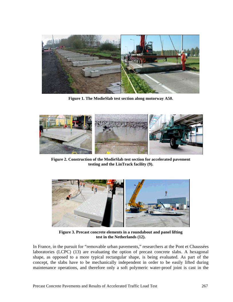
top layer to reduce traffic noise, tube-banks for temperature-control, and space to install instrumentation such as weighing modules or vehicles counters. A pilot section was constructed on a foundation of piles in the access to a rest area on the A50 motorway in the Netherlands (Figure 1). Very good performance was observed after 1.5 years in place (6). There were some unexpected problems with smoothness, which necessitated changes in the production process, and there were problems with raveling (surface deterioration due to aggregate loss) and polishing of the porous concrete wearing course (7). Another 100-m section was built in the summer of 2006 spanning two lanes and the shoulder on the A12 motorway, which reported considerable reduction on tire–pavement noise levels (8).
Structural evaluation of the ModieSlab concept took place at an accelerated pavement testing facility located in Delft, called the LinTrack (Figure 2). A set of four precast slabs were installed and loaded with 250,000 wheel repetitions in the main wheelpath and 10,000 in the slab’s edge at a load level of 75 kN (16,860 lbf). A thinner slab replaced one of the original panels, and 130,000 more repetitions were applied to further investigate structural capacity. Accelerated load test results, combined with finite element modeling, indicated that the ModieSlab concept would be “free of any fatigue deterioration by traffic.” Details on the accelerated testing of the ModieSlab are available elsewhere (7, 9, 10). More research is being conducted in the Netherlands regarding the use of precast pavements for bridges and roundabouts (Figure 3).
Table 1. Design and Performance of Precast Concrete Pavement in Japan (after Hara et al. (5))
Location Area (m2)
Age (yr)
Traffic (veh/day/
lane)
Slab Thick-ness (mm)
Slab Size (m) / Joint
Type Performance
Rating Remarks
Wanatsu, National Hwy, Route 14
343 13 > 3,000 170 1.75x7.0 Horn
Fair Partially overlaid or patched due to raveling by studded tires and joint faulting
Kotsunagi Tunnel
1,193 13 > 3,000 200 1.95x8.5 Horn
Good Partially overlaid or patched due to raveling by studded tires and joint faulting
Inage intersection
990 12 > 3,000 170 2.25–3.0x10.0
Horn
Good Partially patched. Reconstruction of under seal
Kayatsugi Tunnel
900 11 1,000–3,000
170 1.4x7.0 Horn
Good Overlaid on wheelpaths with a thin asphalt layer due to raveling by studded tires
Takao intersection
498 11 > 3,000 170 2.5–3.0x11.0 Dowel
Very good Although small spalling at joints are observed, slabs are sound
Shinamagatsuji Tunnel
289 10 250–1,000
170 2.5-3.0x4.0-
4.65 Dowel
Good It is required to repair joints. Slabs are sound
Higashiyama Tunnel
3,618 9 > 3,000 170 1.67 x10.0 Dowel
Very good Quite sound
1 m2 = 10.764 ft2; 1 mm = 0.039 in.; 1 m = 3.28 ft
Precast Concrete Pavements and Results of Accelerated Traffic Load Test 267
Figure 1. The ModieSlab test section along motorway A50.
Figure 2. Construction of the ModieSlab test section for accelerated pavement
testing and the LinTrack facility (9).
Figure 3. Precast concrete elements in a roundabout and panel lifting
test in the Netherlands (12).
In France, in the pursuit for “removable urban pavements,” researchers at the Pont et Chaussées laboratories (LCPC) (13) are evaluating the option of precast concrete slabs. A hexagonal shape, as opposed to a more typical rectangular shape, is being evaluated. As part of the concept, the slabs have to be mechanically independent in order to be easily lifted during maintenance operations, and therefore only a soft polymeric water-proof joint is cast in the

268 Kohler, du Plessis, Smith, Harvey, and Pyle
joints. The slabs are installed over a granular bed. The base course has a structural function, so research continues to find an easy-to-dig material, yet strong enough to resist long-term traffic loadings. The slabs are 200 mm (8 in.) thick and have an equivalent diameter of 1,540 mm (60 in.). Accelerated pavement testing has been carried out successfully at the fatigue-carrousel at LCPC. A second type of slabs was evaluated with smaller panels and keyed joint to provide some level of load transfer (13).
Figure 4. Accelerated pavement testing of hexagonal slabs and installation
of keyed slabs in France (13).
In 2004, the Ministry of Transportation, Ontario, Canada, carried out a trial project to evaluate construction techniques for precast concrete slab repairs in concrete pavement (11). The trial was carried out on Highway 427, a heavily trafficked freeway in Toronto. The trial project required demonstrations of three precast repair methods that differ in how the base is prepared and how the precast slab is installed and dowelled to the existing concrete pavement. The overall assessment was positive. The precast slabs did not crack, spall, or rock. The minimum requirement of 70 percent load transfer efficiency was met, and other than workmanship issues, the work was carried out within the required timeframes and was showing acceptable performance after a year in service.
EXPERIENCE IN THE UNITED STATES
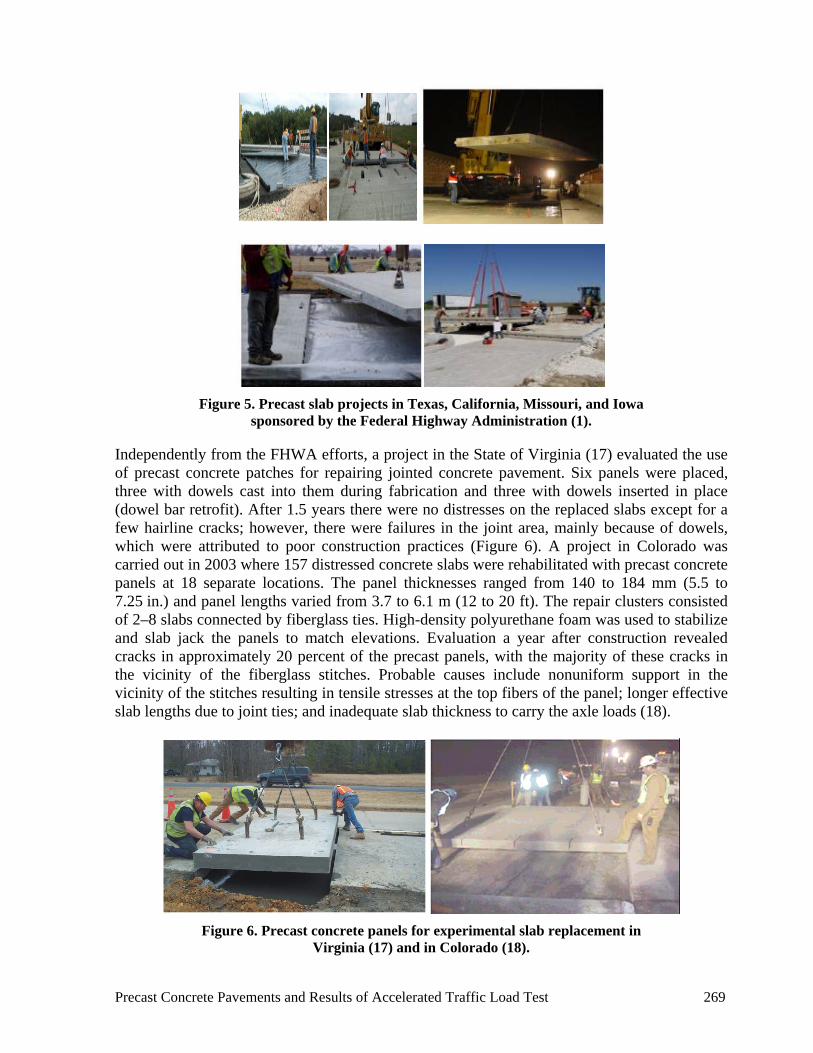
A more concerted effort has taken place in the last few years to implement the use of precast concrete slabs in roadways in the United States. The Federal Highway Administration (FHWA) has been providing engineering support and funding to State agencies in a series of demonstration projects to advance the use of precast pre-stressed concrete pavement (PPCP) for pavement construction and rehabilitation. To date, projects in the States of Texas, California, Missouri, and Iowa have occurred (Figure 5). Each project has required different design elements, demonstrating the flexibility of the PPCP concept (14, 15).
The use of precast paving for full-depth repairs of jointed concrete pavements was demonstrated in Michigan in 2003, as part of FHWA’s Concrete Pavement Technology Program. Eight precast panels plus one conventional full-depth repair were installed along highway I-675. Twelve more precast panels were installed in highway M-25. Some joint failures were observed at the end of the dowel bars due to thermal movement of the pavement (16).
Precast Concrete Pavements and Results of Accelerated Traffic Load Test 269
Figure 5. Precast slab projects in Texas, California, Missouri, and Iowa
sponsored by the Federal Highway Administration (1).
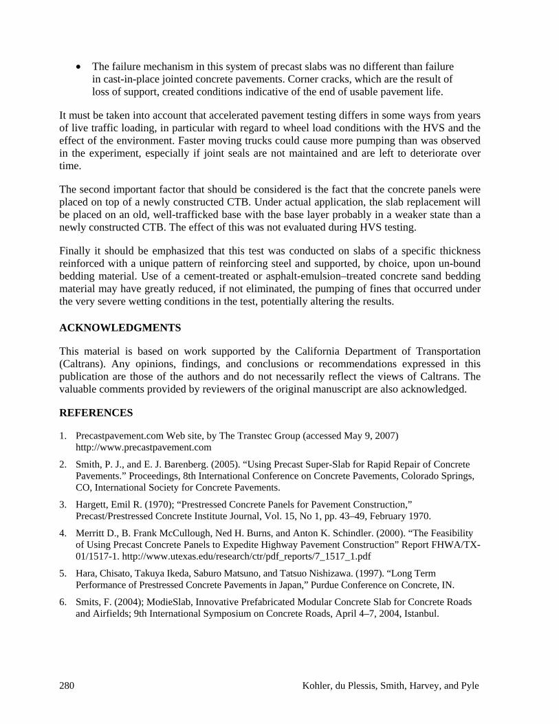
Independently from the FHWA efforts, a project in the State of Virginia (17) evaluated the use of precast concrete patches for repairing jointed concrete pavement. Six panels were placed, three with dowels cast into them during fabrication and three with dowels inserted in place (dowel bar retrofit). After 1.5 years there were no distresses on the replaced slabs except for a few hairline cracks; however, there were failures in the joint area, mainly because of dowels, which were attributed to poor construction practices (Figure 6). A project in Colorado was carried out in 2003 where 157 distressed concrete slabs were rehabilitated with precast concrete panels at 18 separate locations. The panel thicknesses ranged from 140 to 184 mm (5.5 to 7.25 in.) and panel lengths varied from 3.7 to 6.1 m (12 to 20 ft). The repair clusters consisted of 2–8 slabs connected by fiberglass ties. High-density polyurethane foam was used to stabilize and slab jack the panels to match elevations. Evaluation a year after construction revealed cracks in approximately 20 percent of the precast panels, with the majority of these cracks in the vicinity of the fiberglass stitches. Probable causes include nonuniform support in the vicinity of the stitches resulting in tensile stresses at the top fibers of the panel; longer effective slab lengths due to joint ties; and inadequate slab thickness to carry the axle loads (18).
Figure 6. Precast concrete panels for experimental slab replacement in
Virginia (17) and in Colorado (18).

270 Kohler, du Plessis, Smith, Harvey, and Pyle
A very auspicious approach comes from proprietary precast pavement systems that do not involve concrete pre-stressing or post-tensioning. Among these, the Super-Slab™ system is the one with the greater number of built projects. Another system of more recent appearance in the market is called the Kwik Slab™ system (patent pending). Both systems consist of concrete panels that are cast and cured off site and transported to the job site when needed. These types of systems are marketed by companies that use patented technologies.
The remaining portion of this article explains the Super-Slab™ system of precast concrete pavements, its main characteristics, and the evaluation under accelerated pavement loading performed by the University of California Pavement Research Center for the California Department of Transportation (Caltrans).
THE SUPER-SLAB™ SYSTEM
The Super-Slab™ system is a slab-on-grade precast concrete pavement system developed in the State of New York. It was used for the first time to replace the pavement at a bridge toll plaza in that State in 2001. The patented Super-Slab™ system is an assemblage of specially designed precast slabs, methods for installing them, and materials for interlocking them together to create an integrated pavement structure. The system is specifically comprised of the following:
1. Constant-thickness precast slabs that are fabricated to length, width, and thickness as required to a tolerance of +/- 3 mm (0.12 in.).
2. Techniques for precisely grading fully compacted bedding material, to a similar tolerance, to provide near complete subbase support for the precast slabs. To facilitate the grading process, the system utilizes a thin layer of finely graded bedding material placed over the existing subbase.
3. Interlocking dowels, tie bars, and matching slots cast into the bottom of adjacent slabs.
4. A method of installing nonshrink structural grout from the top of the slabs into the slots below.
5. A method of positively filling voids under the slabs by means of a bedding grout distribution system cast into the bottom of each slab.
Standard load transfer dowels are cast at one end of each slab at locations that match the location of dovetail-shaped slots cast in the bottom of each adjacent slab as seen in Figure 7. Similarly, standard tie bars (or the female half of a standard tie bar) are cast at one side of each slab matching the location of slots cast in the adjacent slab. Figure 7 is a closeup view of how dowels and slots align during the placement process.
Two grout ports are cast in the slab over the top each slot to make it accessible for grouting after the slab has been placed. Grout is pumped into one port until it exudes from the other, completing the structural load transfer connection from slab to slab. Fully grouted slabs are essentially the equivalent of cast-in-place pavement slabs and perform the same way. Dowel slots cast on the bottom of the slabs provide two benefits. First, they keep dowel grout on the bottom, protecting it from deicing chemicals and degradation from freeze–thaw activity. Secondly, they keep dowel grout out of sight, maintaining a uniform-looking, high-performance pavement surface. Figure 7 shows a core taken from a dovetail slot/dowel bar connection.

Precast Concrete Pavements and Results of Accelerated Traffic Load Test 271
Figure 7. Doweled joint and core showing dovetail slot/dowel bar connection.
Two grout ports are cast in the slab over the top each slot to make it accessible for grouting after the slab has been placed. Grout is pumped into one port until it exudes from the other, completing the structural load transfer connection from slab to slab. Fully grouted slabs are essentially the equivalent of cast-in-place pavement slabs and perform the same way. Dowel slots cast on the bottom of the slabs provide two benefits. First, they keep dowel grout on the bottom, protecting it from deicing chemicals and degradation from freeze–thaw activity. Secondly, they keep dowel grout out of sight, maintaining a uniform-looking, high-performance pavement surface. Figure 7 shows a core taken from a dovetail slot/dowel bar connection.
While precast slabs can be cast to any thickness, length, and width required, a number of factors must be considered when establishing slab dimensions. Freight costs are minimized when full legal loads are shipped (214-kN [48,000-lbf] load in New York State). Another factor to consider is that repetition of sizes help keep fabrication costs to a minimum.
While single-plane slabs are appropriate for many locations, it is often necessary to provide warped-plane slabs, such as that schematically shown in Figure 8, to accommodate the varying three-dimensional geometry of the highway. The Super-Slab™ system includes the technology for manufacturing slabs to the exact three-dimensional geometry of the location on the highway they will occupy.
Figure 8. Warped precast slabs.
In addition to superelevation transitions, it is sometimes necessary to provide slabs for curved alignments. Slabs for curves are fabricated as slabs with chorded sides, the dimensions of which are determined from the detailed slab layout drawing. It is important to recognize that such slabs can also be warped as well, depending upon the radius and grade of the profile line. Other configurations and alignments may also be required as, for example, highway intersections. The Super-Slab™ system can accommodate any three-dimensional geometry

272 Kohler, du Plessis, Smith, Harvey, and Pyle
The bedding grout distribution system, visible on the bottom of the slab in Figure 9, is comprised of a series of half-round channels cast in the bottom of the slab that extend across the slab to distribute bedding grout to all of the slab contact area. They are accessed from the top of the slab through grout ports cast in at each end of each channel (dots in Figure 7). Also visible in Figure 9 are black foam gaskets glued to the bottom edges (and between half- round channels) of each slab to create discrete, sealed, bedding grout chambers.
Figure 9. Bedding grout channels and gaskets.
While the Super-Slab™ system has been designed to emulate unreinforced, cast-in-place concrete pavement, slabs are reinforced for handling and shipment to the jobsite and to resist the temperature and shrinkage stresses they will be subjected to during curing and storage at the precast facility. The reinforcement also provides the added benefits of enhancing the strength of the slabs to bridge over small voids until the slabs are fully bedded and of keeping cracks tightly closed should they occur at a later time.
Two distinctly different grouts are used in the installation of the Super-Slab™ system. First, rapid-setting, high-strength dowel grout, pumped into the dowel slots, completes the structural connection between individual slabs. Since this grout must reach a minimum compressive strength of 17 MPa (2,465 lbf/in2) before the slabs are opened to traffic, it is important that it be installed in strict accordance with the grout manufacturer’s directions. Secondly, and only after the dowel grout has been installed, a bedding grout mixture of portland cement, water and fluidifying admixture is pumped into the bedding grout distribution system described above. It is important that bedding grout be fluid enough to flow into and effectively fill small voids that may exist between the slab and the subbase surface to provide complete support to the concrete slab. The strength requirement for the bedding grout is 4 MPa (580 lbf/in2) since it functions as only a part of the previously placed bedding material.
Table 2 presents the list of projects completed between 2001 and 2006 with the Super-Slab™ system. One of the projects in New York State was selected by the Technology Implementation Group (TIG) of the American Association of State Highway and Transportation Officials (AASHTO) as one of three focus technologies (out of a field of about 25 that were nominated) in 2006 to be promoted by the AASHTO/TIG Program throughout the country. Ultimately, the TIG elected to promote all current precast slab technologies under the general heading of “Precast Slabs” (19).

Precast Concrete Pavements and Results of Accelerated Traffic Load Test 273
Table 2. List of Super-Slab™ Projects 2002–2006
Project Name State/
Province Type of Project Type of Slabs
Area (m2) Completed
Tappan Zee Plaza New York Continuous Plane 14,679 2002
Dulles International Airport Virginia Intermittent Warped 325 2002
9A Ramp, Tarrytown New York Continuous Warped 1,463 2003
Lincoln Tunnel West Approach New Jersey Continuous Single Plane 753 2003
Belt Parkway, Jamaica New York Continuous Warped 1,489 2003
Korean Parkway Staten Island New York Intermittent Single Plane 822 2003
Port Jefferson New York Intermittent Cross Walks Single Plane 246 2003
I-90, Albany New York Intermittent Single Plane 5,240 2005
Highway 427 Ontario Intermittent, Continuous Single Plane 133 2004
San Bernardino California Test Slabs Single Plane 181 2005
Minneapolis Minnesota Continuous Single Plane 241 2005
Marine Parkway New York Continuous Warped 637 2005
Fordham Rd. Bronx New York Continuous S & W Plane 358 2006
Rt. 7 Crosstown Schenectady New York Continuous, Intersection S & W Plane 2,470 2006
High Speed EZ Pass Slabs New York Special Instrumented S & Crowned 54 2006
1 m2 = 10.764 ft2
ACCELERATED TESTING OF THE SUPER-SLAB™ SYSTEM
The California Department of Transportation (Caltrans), through the University of California (UC) Pavement Research Center, evaluated the use of the Super-Slab™ system as a long-life rehabilitation strategy for concrete pavements. A test site was constructed that consisted of 10 slabs in a 2 by 5 arrangement. The details of the test slab installation were developed to mirror the pavement details of a potential specific project in Caltrans’ District 8. There were four main components of the installation (20):
• A 100-mm (4-in.) cement-treated base (CTB) course placed upon the original ground at the test site.
• A thin (8 mm [0.315 in.]) layer of fine bedding material (stone sand).
• Precast Super-Slabs™, 225 mm (9 in.) thick, placed upon the precisely graded subbase and grouted as described in the foregoing (shown in Figure 10).
• Diamond grinding of the top surface of the slab to meet smoothness requirements of the project.
It is important to note that the use of a bound bedding material (cement-treated sand) was discussed prior to the test. The decision to use unbound stone sand (not treated with cement)

274 Kohler, du Plessis, Smith, Harvey, and Pyle
was made, since that was the material most commonly used on previous projects, recognizing it would likely produce “worst case” results.
Figure 10. Precise placement of the slab on the sand bedding layer and hose with fitting for injecting grout.
Two test sections were evaluated between June 2005 and August 2006 using a heavy-vehicle simulator (HVS), shown in Figure 11. The UC Pavement Research Center operates two of these machines, and they have been used extensively since 1995 to evaluate various paving technologies. The evaluation of the Super-Slab™ system had three main test objectives:
• To evaluate whether traffic can be safely allowed on newly placed slabs before grouting.
• To identify how much traffic loading can the system receive, which relates to long-time performance and years of expected service.
• To determine failure mechanisms.
Figure 11. Test sections layout and HVS during load testing.
Test 1
Test 2

Precast Concrete Pavements and Results of Accelerated Traffic Load Test 275
The instrumentation of the test sections (see Figure 12) consisted of displacement sensors mounted vertically near the two trafficked joints and at mid-panel on each section. Horizontal displacement sensors measured joint opening, and multidepth deflectometers recorded vertical deformation at the various layers of the system directly in the trafficked area. Thermocouple stacks were used to register temperature through the depth of the slabs.
Slab 2 Slab 4
Slab 7 Slab 9
J1 J2 J3 J4 J5
J6 J7
J6(a) J7(a)
J8 J9 J10 J11 J12
H13 H14
H17 H18
H15 H16
H15(a) H16(a)
H15(b) H16(b)
T1T2
T3
T4
T5
T6
T7 T9T8
N
Slab 2 Slab 4
Slab 7 Slab 9
J1 J2 J3 J4 J5
J6 J7
J6(a) J7(a)
J8 J9 J10 J11 J12
H13 H14
H17 H18
H15 H16
H15(a) H16(a)
H15(b) H16(b)
T1T2
T3
T4
T5
T6
T7 T9T8
N
Figure 12. Location of displacement instrumentation and thermocouples.
Traffic loading was applied to each section to simulate the exposure to traffic from the time of placement of the slabs to the time of grouting, which would normally occur during the next nighttime closure. It consisted of approximately 32 hours and 32,000 HVS repetitions with a 60 kN (13,500 lbs) half-axle load, which relates to a total axle load of 120 kN (27,000 lbs). This amount of loading and repetitions were calculated to be the equivalent of about 86,500 equivalent single-axle loads (ESALs). No changes in response, other than those attributable to temperature, were observed during the experiment, and therefore in terms of performance, the ungrouted Super-Slab™ system was verified to withstand at least this level of traffic for southern California conditions.
The thermal deformations (with no traffic loads) were compared before and after grouting. The vertical displacement at an interior corner reduced by grouting from ±1.5 to ±0.5 mm (±0.059 to ±0.020 in.) as shown in Figure 13. In the un-grouted condition each slab curled separately, while after grouting the presence of tie bars and grout in the joint (coming from the tie-bar grout slots), restrained the movement, reducing self-weight stresses and ensuring better support conditions. Along the longitudinal direction, on the exterior corners (on what would be adjacent to the shoulder), the effect of grouting was minimal (see Figure 13).

276 Kohler, du Plessis, Smith, Harvey, and Pyle
Ungrouted 597FDTC: Vertical Thermal Curl
-2.0-1.5-1.0-0.50.00.51.01.52.0
-2000 0 2000 4000 6000
Longitudinal position (mm)
Verti
cal C
url (
mm
)
Night
Day
J2 J3 J4Slab 3
(a) Longitudinal direction before grouting
Ungrouted 597FDTC: Vertical Thermal Curl
-2.0-1.5-1.0-0.50.00.51.01.52.0
0 2000 4000 6000 8000
Transverse position (mm)
Verti
cal C
url (
mm
)
Night
Day
Slab 3 Slab 8
J2 J6 J9
(b) Transverse direction before grouting
Grouted 598FDTC: Vertical Thermal Curl
-2.0-1.5
-1.0-0.5
0.00.5
1.01.5
2.0
-2000 0 2000 4000 6000
Longitudinal position (mm)
Verti
cal C
url (
mm
)
Night
Day
Slab 3
J2 J3 J4
(c) Longitudinal direction after grouting
Grouted 598FDTC: Vertical Thermal Curl
-2.0-1.5-1.0-0.50.00.51.01.52.0
0 2000 4000 6000 8000
Transverse position (mm)
Verti
cal C
url (
mm
)Night
Day
Slab 3 Slab 8
J2 J6 J9
(d) Transverse direction after grouting
Figure 13. Comparison of the vertical deformations caused by thermal curl of the slabs before and after grouting, in the transverse and longitudinal directions.
Regarding responses to wheel load, both sides of the joint moved together after grouting, while they acted independently in the ungrouted condition. Load transfer efficiency changed from less than 10 percent to nearly 100 percent. The vertical deflection at the transverse joint after grouting decreased from about 1.0 to 0.25 mm (0.039 to 0.010) under the 60 kN (13,488 lbf) wheel load. Rocking of the slab was eliminated, as observed by the lack of vertical movement in a joint when the wheel load was on the opposite side of the slab.
To respond to the second and third objectives, the sections were loaded for extended periods under different conditions in the sequence shown in Table 3. Section 1 was heavily loaded to identify failure modes, while section 2 was utilized to determine performance under more realistic, yet accelerated, loading conditions. The numbers of ESALs shown in Table 3 were calculated using a 4.2 power of the ratio between the actual half-axle load and a standard 40-kN (9,000-lbf) load. The climate in southern California has little rainfall. Wet pavement conditions were simulated by pouring water directly on the slabs at the joints. Approximately 380 L (100 gal) of water were poured onto the section per week for the duration of the wet test. Assuming that the water covered the 1 m by 8 m (3.2 ft by 26.3 ft) test area, a total rainfall of approximately 7 mm per day (0.28 in.) was continuously applied during the wet cycle.

Precast Concrete Pavements and Results of Accelerated Traffic Load Test 277
Table 3. Sequence of Test and Loading Conditions
Section Duration (months)
Test and Load Conditions
(pavement / tire type) Load Repetitions
(millions) ESALs
(millions)
1 3 June–September 2005) Dry / Aircraft 1.05 163
2 5 (Sept 2005–February 2006) Dry / Truck dual 2.33 99
2 2 (Feb–May 2006) Wet / Truck dual 1.13 43
1 5 (May–August 2006) Wet / Aircraft 0.54 79
ESAL = equivalent single-axle load
The loading in section 2 consisted of a total of approximately 142.3 million ESALs, applied with dual truck tires (621 kPa [90 lbf/in2] inflation pressure). No sign of any distress was observable at the end of the dry test (99.4 million ESALs). The test consisted of two loading conditions, 243,800 load repetitions at 60 kN (13,488 lbf) and an additional 2.1 million repetitions at a 100-kN (22,481 lbf) load level. The responses captured by the sensors indicated a stable condition. Water application at the joints was then initiated and loading continued. During the wet cycle, loading was applied as follows: 218,600 repetitions at 60 kN (13,489 lbf), 112,000 at 80 kN (17,985 lbf), followed by a final 795,000 repetitions of 100 kN 22,481 lbf).
No distresses were observable at this stage either, despite the fact that considerable pumping of material from under the slab occurred during the wet trafficking. The pumping of fine sand, however, did not result in any significant rise in corner deflections. An investigation was carried out to evaluate the extent of the suspected voids under the slab caused by pumping. It revealed that the pumped material was comprised of the finer particles from the sand bedding layer and disintegrated bedding grout. There was no clearly noticeable void in the wheelpath under the joint, but there were rather widespread marks of washed fines.
Figure 14. Investigation of void under the slab in section 2.
Assuming an AADTT (annual average daily truck traffic) of 7,500 per direction and 3 ESALs per heavy vehicle, and assuming 60 percent truck traffic in the slow lane, the total ESALs per day are currently 13,500 on a highway like I-15 in southern California. If it is assumed that this traffic level exists for approximately 75 percent of the year, the total truck traffic would amount to 3.7 million ESALS per year per slow lane. Assuming a growth factor of 3 percent, it would

278 Kohler, du Plessis, Smith, Harvey, and Pyle
take approximately 25 years to apply the same amount of ESALs that were simulated by the HVS in section 2 during the dry and wet cycle (142 million in total). It should be noted that testing in section 2 was discontinued at this traffic level, and there were no distresses on the pavement section.
Loading in section 1 was applied with an aircraft tire (1.45 MPa [210 lbf/in2] inflation pressure), able to take the higher load levels, and 242 million ESALs were applied. Using similar calculations as for section 2, it would take 37 years to reach the traffic level simulated in section 1 (242 million ESALs). This expected life should be used with caution, as it involves many assumptions in the traffic calculation in addition to the differences between loading with HVS traffic and with real traffic.
Corner cracks appeared next to one of the two loaded joints in section 1. These structural corner cracks, on both sides of the joint, were first observed at 0.762 million load repetitions and were fully developed at 0.845 million load repetitions. HVS trafficking in dry conditions was stopped when, after the cracks had appeared, the pavement responses were once again stable. After the wet traffic was initiated, the slabs were able to withstand 79 million ESALs before traffic had to be stopped, a clear indication of a still sound structural condition of the cracked slabs.
Figure 15. Fully developed corner cracks at one of the transverse joints of
section 1, when loaded in dry pavement conditions
Failure of the section was reached in the form of a localized collapse in one of the joints and a more extended corner crack on the other joint. Forensic investigation revealed that the localized failure happened between dowel bars, exactly where the channelized traffic loaded the pavement. Even though the failure happened at the location of one of the multi-depth deflectometer sensors, it was concluded that this had no effect. The combined observations point toward concrete fatigue under channelized traffic and the loss of support caused by pumping. The other joint presented a failure that can be considered typical of cast-in-place, with large concrete cracks. Both failed joints are shown in Figure 16 (as size reference, the brass sensors’ caps are 75 mm [2.95 in.] in diameter) (21).

Precast Concrete Pavements and Results of Accelerated Traffic Load Test 279
Figure 16. End of life at the two joints of section 1, loaded to failure.
Drill cores obtained from various locations in both test sections indicated very good performance of the dowel grout. There was no sign of dowel loosening, which means that the grout was strong enough to sustain the compressive forces of the dowel as the load was transmitted across the joint. Likewise, there were no signs of bonding issues between the grout and the surrounding concrete of the slot.
SUMMARY AND CONCLUSIONS
This paper summarizes experiences around the world with the use of precast slabs for pavement rehabilitation. The results show that the technology is still evolving, but that in the United States products such as Super-Slab™ are starting to have a major impact with a number of practical applications in critical areas. Evaluation of Super-Slab™ under accelerated loading provided Caltrans with answers about performance concerns. The general conclusion is that the use of precast slabs for concrete pavement rehabilitation is being seriously evaluated in the United States at various levels, and it is being favorably considered by FHWA, AASHTO, and various State and other highway agencies. There is also growing interest in this technology in other countries.
The following conclusions are derived from the experiment conducted for Caltrans in which an HVS was used to test the structural performance of the Super-Slab™ system under accelerated conditions:
• The Super-Slab™ system of precast slabs can be safely opened to traffic in the un-grouted condition, so that the panels can be installed in consecutive nights rather than completing the entire installation at one time. This allows for the old slabs to be removed and precast slabs placed in position one night, and for completing the grouting procedure on the following night.
• The life of this system of precast slabs, when used as detailed for this test, is estimated to be between 142 and 242 million ESALs. These numbers result from estimated traffic applied in section 2, which did not fail, and in section 1, which failed under very high load levels. Taking as an example highway I-15 in San Bernardino County, California, this number of ESALs could be assumed to be equivalent to more than 25 years of service, perhaps about 37 years, before reaching failure.
280 Kohler, du Plessis, Smith, Harvey, and Pyle
• The failure mechanism in this system of precast slabs was no different than failure in cast-in-place jointed concrete pavements. Corner cracks, which are the result of loss of support, created conditions indicative of the end of usable pavement life.
It must be taken into account that accelerated pavement testing differs in some ways from years of live traffic loading, in particular with regard to wheel load conditions with the HVS and the effect of the environment. Faster moving trucks could cause more pumping than was observed in the experiment, especially if joint seals are not maintained and are left to deteriorate over time.
The second important factor that should be considered is the fact that the concrete panels were placed on top of a newly constructed CTB. Under actual application, the slab replacement will be placed on an old, well-trafficked base with the base layer probably in a weaker state than a newly constructed CTB. The effect of this was not evaluated during HVS testing.
Finally it should be emphasized that this test was conducted on slabs of a specific thickness reinforced with a unique pattern of reinforcing steel and supported, by choice, upon un-bound bedding material. Use of a cement-treated or asphalt-emulsion–treated concrete sand bedding material may have greatly reduced, if not eliminated, the pumping of fines that occurred under the very severe wetting conditions in the test, potentially altering the results.
ACKNOWLEDGMENTS
This material is based on work supported by the California Department of Transportation (Caltrans). Any opinions, findings, and conclusions or recommendations expressed in this publication are those of the authors and do not necessarily reflect the views of Caltrans. The valuable comments provided by reviewers of the original manuscript are also acknowledged.
REFERENCES
1. Precastpavement.com Web site, by The Transtec Group (accessed May 9, 2007) http://www.precastpavement.com
2. Smith, P. J., and E. J. Barenberg. (2005). “Using Precast Super-Slab for Rapid Repair of Concrete Pavements.” Proceedings, 8th International Conference on Concrete Pavements, Colorado Springs, CO, International Society for Concrete Pavements.
3. Hargett, Emil R. (1970); “Prestressed Concrete Panels for Pavement Construction,” Precast/Prestressed Concrete Institute Journal, Vol. 15, No 1, pp. 43–49, February 1970.
4. Merritt D., B. Frank McCullough, Ned H. Burns, and Anton K. Schindler. (2000). “The Feasibility of Using Precast Concrete Panels to Expedite Highway Pavement Construction” Report FHWA/TX-01/1517-1. http://www.utexas.edu/research/ctr/pdf_reports/7_1517_1.pdf
5. Hara, Chisato, Takuya Ikeda, Saburo Matsuno, and Tatsuo Nishizawa. (1997). “Long Term Performance of Prestressed Concrete Pavements in Japan,” Purdue Conference on Concrete, IN.
6. Smits, F. (2004); ModieSlab, Innovative Prefabricated Modular Concrete Slab for Concrete Roads and Airfields; 9th International Symposium on Concrete Roads, April 4–7, 2004, Istanbul.
Precast Concrete Pavements and Results of Accelerated Traffic Load Test 281
7. van Dommelen, A.E., J. Van Der Kooij, L. J. M. Houben, and A. A. A. Molenaar. (2004). LinTrack APT research supports accelerated implementation of innovative pavement concepts in the Netherlands. Second International Conference on Accelerated Pavement Testing, September 2004, Minneapolis, MN.
8. Sandberg, Ulf. (2007). Presentation at the summer meeting of TRB committee on Transportation-related Noise and Vibration, San Luis Obispo, CA.
9. Houben, L. J. M., Poot, S., Huurman, M., Kooij, J. Van Der. (2004). “Developments on the ModieSlab Innovative Concrete Pavement Concept,” 9th International Symposium on Concrete Roads, April 4-7, 2004, Istanbul.
10. Houben, L. J. M., Huurman, M., Kooij, J. Van Der, Poot, S. (2004). “Apt Testing and 3D Finite Element Analysis of ModieSlab Modular Pavement Structures”. Proceedings 2nd International Conference on Accelerated Pavement Testing, Minneapolis, MN, September 26–29, 2004.
11. Lane, B., and T. Kazmierowski. (2005). “Use of Innovative Precast Concrete Slab Repair Technology in Canada.” Proceedings of the 8th International Conference on Concrete Pavements, Colorado Springs, CO.
12. Marc J. A. Stet, Adrian J. van Leest, George Jurriaans. (2004). “Guidelines For Concrete Roundabouts; The Dutch Practice,” 9th International Symposium on Concrete Roads, April 4–7, 2004, Istanbul.
13. DeLarrard, F., Balay, J-M, Sedran, T., Laurent, G., Leroux, A., Maribas, J., Vulcano-Greullet, N., Sagnard, N; Masson J-M; and Bélouard R. (2006). “Development of a Removable Urban Pavement Technology.” 10th International Symposium on Concrete Roads, September 18–22, 2006, Brussels.
14. Concrete Pavement Technology Update, July 2005, Federal Highway Administration, FHWA-IF-05-028. http://www.fhwa.dot.gov/pavement/concrete/cptu201.pdf
15. Concrete Pavement Technology Update October 2006, Federal Highway Administration, FHWA-IF-07-001. http://www.fhwa.dot.gov/pavement/concrete/cptu401.pdf
16. Buch, N., Lane, B., and Kazmierowski, T. (2006). “The Early-Age Evaluation of Full-Depth Precast Panels: Canadian and Michigan Experiences”; Proceedings International Conference on Long-Life Concrete Pavements Rosemont, IL, October 25–27, 2006.
17. Hossain, S., Ozyildirim, C., and Tate, T. (2006). “Evaluation of Precast Patches on U.S. 60 Near the New Kent and James City County Line.” http://www.virginiadot.org/vtrc/main/online_reports/ pdf/06-r22.pdf
18. Buch, N., Vongchusiri, K., Meeker, B., Command, M., and Ardani, A. (2005). “Accelerated Repair of Jointed Concrete Pavements (JCP) Using Precast Concrete Panels-Colorado Experience,” Proceedings of the 8th International Conference on Concrete Pavements, Colorado Springs, CO.
19. Precast Concrete Paving Slabs, AASHTO Technology Implementation Group Web site http://tig.transportation.org/?siteid=57&pageid=1826
20. Kohler, E., Du Plessis, L., and Theyse, H. (2006). “Construction and Preliminary HVS Tests of Precast Concrete Pavement Slabs.” Draft Research Report UCPRC-RR-2006-10.
21. Kohler, E., Du Plessis, L., and Harvey, J. (2007). “HVS Testing of Precast PCC Panels as an Alternative Long-Life Pavement Rehabilitation Strategy.