PRE3 - Home - Hilti United Kingdom Bedienungsanleitung de Operating instructions en Mode d’emploi...
15
PRE 3 Bedienungsanleitung de Operating instructions en Mode d’emploi fr Istruzioni d’uso it Manual de instrucciones es Manual de instruções pt Gebruiksaanwijzing nl Brugsanvisning da Bruksanvisning sv Bruksanvisning no Käyttöohje fi Οδηγιες χρησεως el Használati utasítás hu Instrukcja obsługi pl Инструкция по зксплуатации ru Návod k obsluze cs Návod na obsluhu sk Upute za uporabu hr Navodila za uporabo sl Ръководство за обслужване bg Instrucţiuni de utilizare ro Kulllanma Talimatı tr ar Lietošanas pamācība lv Instrukcija lt Kasutusjuhend et IНСТРУКЦIЯ З ЕКСПЛУАТАЦIЇ uk ja ko cn Printed: 08.07.2013 | Doc-Nr: PUB / 5070312 / 000 / 01
Transcript of PRE3 - Home - Hilti United Kingdom Bedienungsanleitung de Operating instructions en Mode d’emploi...

PRE 3
Bedienungsanleitung deOperating instructions enMode d’emploi frIstruzioni d’uso itManual de instrucciones esManual de instruções ptGebruiksaanwijzing nlBrugsanvisning daBruksanvisning svBruksanvisning noKäyttöohje fiΟδηγιες χρησεως elHasználati utasítás huInstrukcja obsługi plИнструкция по зксплуатации ruNávod k obsluze csNávod na obsluhu skUpute za uporabu hrNavodila za uporabo slРъководство за обслужване bgInstrucţiuni de utilizare roKulllanma Talimatı tr
arLietošanas pamācība lvInstrukcija ltKasutusjuhend etIНСТРУКЦIЯ З ЕКСПЛУАТАЦIЇ uk
jakocn
Printed: 08.07.2013 | Doc-Nr: PUB / 5070312 / 000 / 01

1
Printed: 08.07.2013 | Doc-Nr: PUB / 5070312 / 000 / 01

1
2
2
1
2
3
4
1
5
075074073072071070069068067066065064063062061060059058057056055054053052051050049048047046045
076
077
078
143
144
145
208
209
210
271
272
273
339338337
3
4
2
1
6
6
5
6
3
4
2
6
1
7
Printed: 08.07.2013 | Doc-Nr: PUB / 5070312 / 000 / 01

>1/4s
ORIGINAL OPERATING INSTRUCTIONS
PRE 3 rotating laser
It is essential that the operating instructionsare read before the tool is operated for thefirst time.Always keep these operating instructions to-gether with the tool.Ensure that the operating instructions arewith the tool when it is given to other persons.
Contents Page1 General information 122 Description 133 Accessories 154 Technical data 155 Safety instructions 166 Before use 177 Operation 188 Care and maintenance 199 Disposal 2010 Manufacturer’s warranty - tools 2111 FCC statement (applicable in US) / IC
statement (applicable in Canada) 2112 EC declaration of conformity (original) 22
1 These numbers refer to the corresponding illustra-tions. The illustrations can be found on the fold-out coverpages. Keep these pages open while studying the oper-ating instructions.In these operating instructions, the designation “the tool”always refers to the PRE 3 rotating laser.
Parts, operating controls and indicators1
PRE 3 rotating laser@ Laser beam (plane of rotation); Rotating head= Control panel, display% Grip& Battery compartment( Li‑ion battery) Base plate with ⁵/₈" thread
PRE 3 control panel+ On/off button§ Auto-leveling LED/ Shock warning deactivation LED: Inclination angle LED· Battery status indicator
PRA 84 battery$ Catch£ Charging cord socket| Battery status indicator LED
1 General information1.1 Safety notices and their meaningDANGERDraws attention to imminent danger that will lead toserious bodily injury or fatality.
WARNINGDraws attention to a potentially dangerous situation thatcould lead to serious personal injury or fatality.
CAUTIONDraws attention to a potentially dangerous situation thatcould lead to slight personal injury or damage to theequipment or other property.
NOTEDraws attention to an instruction or other useful informa-tion.
1.2 Explanation of the pictograms and otherinformation
Symbols
Read theoperatinginstructionsbefore use.
Generalwarning
Revolutionsper minute
Return wastematerial forrecycling.
Do not lookinto thebeam.
en
12
Printed: 08.07.2013 | Doc-Nr: PUB / 5070312 / 000 / 01

Symbol for Laser Class II / Class 2
Laser class IIaccording to
CFR 21, § 1040(FDA)
Laser class 2according toEN 60825-3:2007
Location of identification data on the toolThe type designation and serial number can be found onthe type identification plate on the tool. Make a note ofthis data in your operating instructions and always referto it when making an enquiry to your Hilti representativeor service department.
Type:
Generation: 01
Serial no.:
2 Description2.1 Use of the product as directedThe Hilti PRE 3 is a rotating laser tool that emits a rotating laser beam.The tool is designed to be used for determining, transferring and checking reference levels in the horizontal plane.Examples of uses are the transferring of datum lines and heights.Use of tools or mains adapters which show visible signs of damage is not permissible.Operation outdoors or in damp conditions in “Charging during operation mode” is not permissible.Hilti supplies various accessories which allow the tool to be used with maximum efficiency.The tool and its ancillary equipment may present hazards when used incorrectly by untrained personnel or when usednot as directed.To avoid the risk of injury, use only genuine Hilti accessories and insert tools.Observe the information printed in the operating instructions concerning operation, care and maintenance.Take the influences of the surrounding area into account. Do not use the appliance where there is a risk of fire orexplosion.Modification of the tool is not permissible.
2.2 FeaturesUsing the tool, a single person can level and align in all planes very quickly and with great accuracy (tool used inconjunction with the PRA 30 laser receiver).The preset speed of rotation is 300 U/min (r.p.m.). The tool levels itself automatically after it is switched on (automaticleveling within an inclination of 10°(±5°)).LEDs indicate the tool’s current operating status.The PRE 3 is easy to set up and operate and features a rugged casing. The tool is powered by a rechargeable Li‑ionbattery which can be charged while the tool is in operation.
2.3 Horizontal planeAfter switching on, the tool levels itself automatically by way of 2 built-in servo motors.
2.4 Inclined plane (manual alignment in the desired plane of inclination)The desired inclination can be set with the aid of the PRA 78 slope adapter. For further information on using the slopeadapter, please refer to the instruction sheet supplied with the PRA 78.
2.5 Shock warningThe built-in shock warning function (becomes active one minute after completion of auto-leveling). The tool goes intowarning mode if it is knocked off level (due to vibration or impact) while in operation: all LEDs blink; the head of thelaser stops rotating; The laser beam is switched off.
2.6 Automatic cut-outThe laser does not switch on and all LEDs blink if the tool is set up outside its self-levelling range or movement isblocked mechanically. The tool can be set up on a tripod with a 5/8" thread or stood directly on some other steadysurface (free of vibration). When automatic leveling is activated for one or both axes, the built-in servo system ensuresthat the specified accuracy is maintained. The tool switches itself off when automatic leveling cannot be achieved (tool
en
13
Printed: 08.07.2013 | Doc-Nr: PUB / 5070312 / 000 / 01

set up outside its leveling range or physical impediment of the mechanism) or when knocked off level (see “Shockwarning” section).
NOTEIf the correct level cannot be achieved, the laser switches itself off and all LEDs blink.
2.7 Items supplied1 PRE 3 rotating laser1 PRA 30 laser receiver1 PRA 80 laser receiver holder1 PRE 3 operating instructions1 PRA 30 operating instructions1 PRA 84 battery1 PRA 85 mains adapter2 Batteries (size AA cells)2 Manufacturer’s certificates1 Hilti toolbox
2.8 Operating status indicatorsThe tool is equipped with the following operating status indicators: auto-leveling LED, inclination angle LED and shockwarning LED.
2.9 LED indicatorsAuto-leveling LED The green LED blinks. The tool is in the leveling phase.
The green LED lights con-stantly.
The tool has leveled itself / is operatingnormally.
Shock warning LED The shock warning LED lightsorange.
The LED lights orange after deactivationof the shock warning.
Inclination indicator The orange LED lights con-stantly.
The inclination angle LED indicates thatthe manual inclination function is active.
All LEDs All LEDs blink. The tool has been bumped or broughtout of level.
2.10 Charge status of the Li‑ion battery during operation
LEDs light constantly LEDs blink Charge status CLED 1,2,3,4 - C ≧ 75 %LED 1,2,3 - 50 % ≦ C < 75 %LED 1,2 - 25 % ≦ C < 50 %LED 1 - 10 % ≦ C < 25 %- LED 1 C < 10 %
2.11 Charge status of the Li‑ion battery during charging while fitted to the tool
LEDs light constantly LEDs blink Charge status CLED 1,2,3,4 - = 100%LED 1,2,3 LED 4 75 % ≦ C 100 %LED 1,2 LED 3 50 % ≦ C75 %LED 1 LED 2 25 % ≦ C 50 %- LED 1 C < 25 %
en
14
Printed: 08.07.2013 | Doc-Nr: PUB / 5070312 / 000 / 01

2.12 Charge status of the Li‑ion battery during charging while not fitted to the toolIf the red LED lights constantly, the battery is being charged.If the red LED doesn’t light, the battery is fully charged.
3 AccessoriesDesignation Short designationVarious tripods PUA 20, PA 921, PUA 30 and PA 931/2Telescopic staffs PA 950/960, PA 951/961, PA 962 and PUA 50Slope adapter PRA 78Car charging connector PRA 86Height transfer device PRA 81
4 Technical dataRight of technical changes reserved.
PRE 3Receiving range (diameter) With PRA 30 laser receiver: 2…400 m (6 to 1300 ft)Accuracy per 10 m (±0.5 mm) horizontal distance 0.5 mm
(0.02" in 32 ft,+75° F), temperature 24°CLaser class Class 2, visible, 635 nm, < 1 mW (EN 60825-3:2007 /
IEC 60825 - 3:2007); class II (CFR 21 § 1040 (FDA))Speed of rotation 300/min ± 10%Self-leveling range 10°(±5°)Power source 7.2V/ 4.5 Ah Li‑ion batteryBattery life Temperature +20°C (+68°F), Li‑ion battery: ≥ 40 hOperating temperature range -20…+50°C (-4°F to 122°F)Storage temperature range (dry) -25…+60°C (-13°F to 140°F)Protection class IP 56 (in accordance with IEC 60529) (not in “charging
during operation” mode)Tripod thread ⁵⁄₈" X 18Weight (including battery) 2.4 kg (5.3 lbs)Dimensions (L x W x H) 252 mm X 252 mm X 201 mm (10" x 10" x 8")
PRA 84 Li‑ion batteryRated voltage (normal mode) 7.2 VMaximum voltage (during operation or during chargingwhile in operation)
13 V
Rated current 120 mAhCharging time 2 h / +32°C / Battery is 80% chargedOperating temperature range -20…+50°C (-4°F to 122°F)Storage temperature range (dry) -25…+60°C (-13°F to 140°F)Charging temperature range (also for charging duringoperation)
+0…+40°C (32° to +104°F)
Weight 0.3 kg (0.67 lbs)Dimensions (L x W x H) 160 mm X 45 mm X 36 mm (6.3" x 1.8" x 1.4")
en
15
Printed: 08.07.2013 | Doc-Nr: PUB / 5070312 / 000 / 01
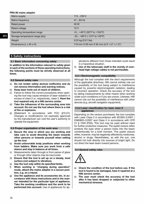
PRA 85 mains adapterMains supply 115…230 VMains frequency 47…63 HzRated power 40 WRated voltage 12 VOperating temperature range +0…+40°C (32°F to +104°F)Storage temperature range (dry) -25…+60°C (-13°F to 140°F)Weight 0.23 kg (0.51 lbs)Dimensions (L x W x H) 110 mm X 50 mm X 32 mm (4.3" x 2" x 1.3")
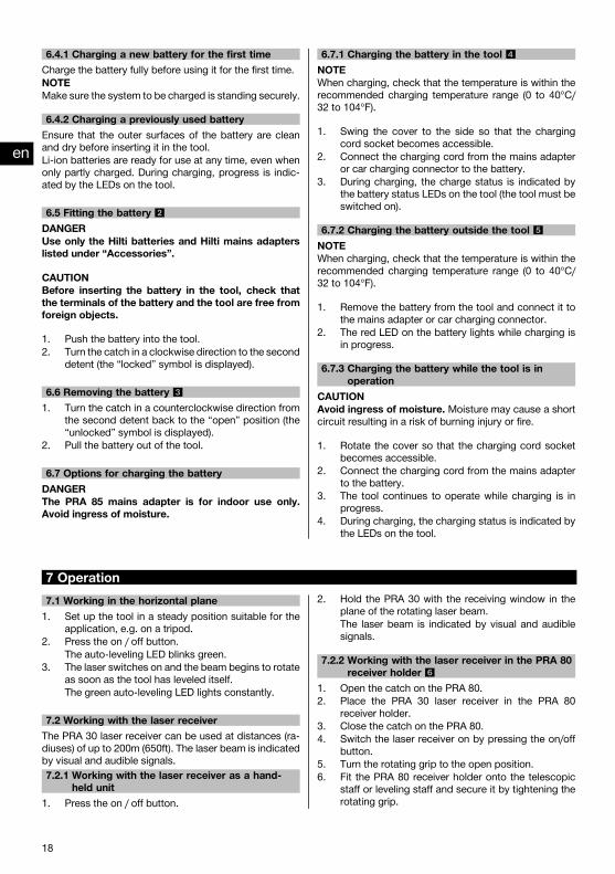
5 Safety instructions5.1 Basic information concerning safetyIn addition to the information relevant to safety givenin each of the sections of these operating instructions,the following points must be strictly observed at alltimes.
5.2 General safety rulesa) Do not render safety devices ineffective and do
not remove information and warning notices.b) Keep laser tools out of reach of children.c) Failure to follow the correct procedures when open-
ing the tool may cause emission of laser radiation inexcess of class 2 or, respectively, class 3. Have thetool repaired only at a Hilti service center.
d) Take the influences of the surrounding area intoaccount. Do not use the tool where there is a riskof fire or explosion.
e) (Statement in accordance with FCC §15.21):Changes or modifications not expressly approvedby the manufacturer can void the user’s authority tooperate the equipment.
5.3 Proper organization of the work areaa) Secure the area in which you are working and
take care to avoid directing the beam towardsother persons or towards yourself when settingup the tool.
b) Avoid unfavorable body positions when workingfrom ladders. Make sure you work from a safestance and stay in balance at all times.
c) Measurements taken through or from panes of glassor through other objects may be inaccurate.
d) Ensure that the tool is set up on a steady, levelsurface (not subject to vibration).
e) Use the tool only within its specified limits.f) When working in “charging during operation”
mode, attach the mains adapter in a secure posi-tion, e.g. on a tripod.
g) Use the appliance and its accessories etc. in ac-cordance with these instructions and in the man-ner intended for the particular type of appliance.Take the working conditions and the work to beperformed into account. Use of appliances for ap-
plications different from those intended could resultin a hazardous situation.
h) Use of the telescopic staff in the vicinity of over-head high voltage cables is not permissible.
5.3.1 Electromagnetic compatibilityAlthough the tool complies with the strict requirementsof the applicable directives, Hilti cannot entirely rule outthe possibility of the tool being subject to interferencecaused by powerful electromagnetic radiation, leadingto incorrect operation. Check the accuracy of the toolby taking measurements by other means when workingunder such conditions or if you are unsure. Likewise, Hilticannot rule out the possibility of interference with otherdevices (e.g. aircraft navigation equipment).
5.3.2 Laser classification for laser class IIappliances
Depending on the version purchased, the tool complieswith Laser Class 2 in accordance with IEC825-3:2007 /EN60825-3:2007 and Class II in accordance with CFR21 § 1040 (FDA). This tool may be used without needfor further protective measures. The eyelid closure reflexprotects the eyes when a person looks into the beamunintentionally for a brief moment. This eyelid closurereflex, however, may be negatively affected bymedicines,alcohol or drugs. Nevertheless, as with the sun, oneshould not look directly into sources of bright light. Donot direct the laser beam toward persons.
5.4 General safety rules
a) Check the condition of the tool before use. If thetool is found to be damaged, have it repaired at aHilti service center.
b) The user must check the accuracy of the toolafter it has been dropped or subjected to othermechanical stresses.
en
16
Printed: 08.07.2013 | Doc-Nr: PUB / 5070312 / 000 / 01

c) When the tool is brought into a warm environmentfrom very cold conditions, or vice-versa, allow itto become acclimatized before use.
d) If mounting on an adapter, check that the tool isscrewed on securely.
e) Keep the laser exit aperture clean to avoid meas-urement errors.
f) Although the tool is designed for the tough condi-tions of jobsite use, aswith other optical and elec-tronic instruments (e.g. binoculars, spectacles,cameras) it should be treated with care.
g) Although the tool is protected to prevent entryof dampness, it should be wiped dry each timebefore being put away in its transport container.
h) Check the tool before using it for important meas-uring work.
i) Check the accuracy of the measurements severaltimes during use of the tool.
j) Use the mains adapter only for connecting to themains supply.
k) Check to ensure that the tool and mains adapterdo not present an obstacle that could lead to arisk of tripping and personal injury.
l) Ensure that the workplace is well lit.m) Avoid body contact with earthed or grounded
surfaces, such as pipes, radiators, ranges andrefrigerators. There is an increased risk of electricshock if your body is earthed or grounded.
n) Check the condition of the extension cord andreplace it if damage is found. Do not touch themains adapter if the extension cord or mains ad-apter are damagedwhile working. Disconnect thesupply cord plug from the power outlet. Damagedsupply cords or extension cords present a risk ofelectric shock.
o) Do not expose the supply cord to heat, oil or sharpedges.
p) Never operate the mains adapter when it is dirtyor wet. Dust (especially dust from conductive ma-
terials) or dampness adhering to the surface ofthe mains adapter may, under unfavorable condi-tions, lead to electric shock. Dirty or dusty toolsshould thus be checked at a Hilti service centerat regular intervals, especially if used frequentlyfor working on conductive materials.
q) Avoid touching the contacts.
5.4.1 Battery tool use and carea) Check that the tool is switched off before fitting
the battery. Use only the Hilti battery approved foruse with this tool.
b) Do not expose batteries to high temperatures orfire. This presents a risk of explosion.
c) Do not disassemble, squash or incinerate batter-ies and do not subject them to temperatures over75°C. A risk of fire, explosion or injury through con-tact with caustic substances may otherwise result.
d) Avoid ingress of moisture. Moisture may cause ashort circuit resulting in a risk of burning injury or fire.
e) Do not use batteries other than those approvedfor use with the applicable tool or appliance. Useof other batteries or use of the battery for purposesfor which it is not intended presents a risk of fire andexplosion.
f) Observe the special instructions applicable to thetransport, storage and use of Li-ion batteries.
g) Avoid short-circuiting the battery.Before insertingthe battery in the tool, check that the terminals ofthe battery and the tool are free from foreign objects.Short-circuiting the battery terminals presents a riskof fire, explosion or contact with caustic substances.
h) Do not charge or continue to use damaged bat-teries (e.g. batteries with cracks, broken parts,bent or pushed-in and/or pulled-out contacts).
i) Use only the specified battery to power the tooland use only the PRA 85 mains adapter or PRA 86car charging connector for charging. Failure toobserve these points may result in damage to thetool.
6 Before useNOTEThe tool may be powered only by the Hilti PRA 84 battery,which is manufactured in accordance with IEC 60285.
6.1 Switching the tool onPress the on / off button.NOTEAfter switching on, the tool begins to level itself automat-ically.
6.2 LED indicatorsPlease refer to section 2 “Description”.
6.3 Battery use and careStore the battery in a cool, dry place. Never store thebattery where it is exposed to direct sunlight or sources
of heat, e.g. on heaters / radiators or behind a motorvehicle windscreen. Batteries that have reached the endof their life must be disposed of safely and correctly toavoid environmental pollution.
6.4 Charging the battery
DANGERUse only the Hilti batteries and Hilti mains adapterslisted under “Accessories”.
en
17
Printed: 08.07.2013 | Doc-Nr: PUB / 5070312 / 000 / 01
6.4.1 Charging a new battery for the first timeCharge the battery fully before using it for the first time.NOTEMake sure the system to be charged is standing securely.
6.4.2 Charging a previously used batteryEnsure that the outer surfaces of the battery are cleanand dry before inserting it in the tool.Li-ion batteries are ready for use at any time, even whenonly partly charged. During charging, progress is indic-ated by the LEDs on the tool.
6.5 Fitting the battery 2
DANGERUse only the Hilti batteries and Hilti mains adapterslisted under “Accessories”.
CAUTIONBefore inserting the battery in the tool, check thatthe terminals of the battery and the tool are free fromforeign objects.
1. Push the battery into the tool.2. Turn the catch in a clockwise direction to the second
detent (the “locked” symbol is displayed).
6.6 Removing the battery 3
1. Turn the catch in a counterclockwise direction fromthe second detent back to the “open” position (the“unlocked” symbol is displayed).
2. Pull the battery out of the tool.
6.7 Options for charging the batteryDANGERThe PRA 85 mains adapter is for indoor use only.Avoid ingress of moisture.
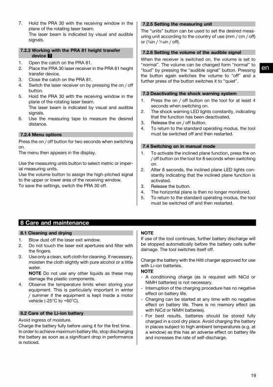
6.7.1 Charging the battery in the tool 4NOTEWhen charging, check that the temperature is within therecommended charging temperature range (0 to 40°C/32 to 104°F).
1. Swing the cover to the side so that the chargingcord socket becomes accessible.
2. Connect the charging cord from the mains adapteror car charging connector to the battery.
3. During charging, the charge status is indicated bythe battery status LEDs on the tool (the tool must beswitched on).
6.7.2 Charging the battery outside the tool 5NOTEWhen charging, check that the temperature is within therecommended charging temperature range (0 to 40°C/32 to 104°F).
1. Remove the battery from the tool and connect it tothe mains adapter or car charging connector.
2. The red LED on the battery lights while charging isin progress.
6.7.3 Charging the battery while the tool is inoperation
CAUTIONAvoid ingress of moisture. Moisture may cause a shortcircuit resulting in a risk of burning injury or fire.
1. Rotate the cover so that the charging cord socketbecomes accessible.
2. Connect the charging cord from the mains adapterto the battery.
3. The tool continues to operate while charging is inprogress.
4. During charging, the charging status is indicated bythe LEDs on the tool.
7 Operation7.1 Working in the horizontal plane1. Set up the tool in a steady position suitable for the
application, e.g. on a tripod.2. Press the on / off button.
The auto-leveling LED blinks green.3. The laser switches on and the beam begins to rotate
as soon as the tool has leveled itself.The green auto-leveling LED lights constantly.
7.2 Working with the laser receiverThe PRA 30 laser receiver can be used at distances (ra-diuses) of up to 200m (650ft). The laser beam is indicatedby visual and audible signals.7.2.1 Working with the laser receiver as a hand-
held unit1. Press the on / off button.
2. Hold the PRA 30 with the receiving window in theplane of the rotating laser beam.The laser beam is indicated by visual and audiblesignals.
7.2.2 Working with the laser receiver in the PRA 80receiver holder 6
1. Open the catch on the PRA 80.2. Place the PRA 30 laser receiver in the PRA 80
receiver holder.3. Close the catch on the PRA 80.4. Switch the laser receiver on by pressing the on/off
button.5. Turn the rotating grip to the open position.6. Fit the PRA 80 receiver holder onto the telescopic
staff or leveling staff and secure it by tightening therotating grip.
en
18
Printed: 08.07.2013 | Doc-Nr: PUB / 5070312 / 000 / 01
7. Hold the PRA 30 with the receiving window in theplane of the rotating laser beam.The laser beam is indicated by visual and audiblesignals.
7.2.3 Working with the PRA 81 height transferdevice 7
1. Open the catch on the PRA 81.2. Place the PRA 30 laser receiver in the PRA 81 height
transfer device.3. Close the catch on the PRA 81.4. Switch the laser receiver on by pressing the on / off
button.5. Hold the PRA 30 with the receiving window in the
plane of the rotating laser beam.The laser beam is indicated by visual and audiblesignals.
6. Use the measuring tape to measure the desireddistance.
7.2.4 Menu optionsPress the on / off button for two seconds when switchingon.The menu then appears in the display.
Use the measuring units button to select metric or imper-ial measuring units.Use the volume button to assign the high-pitched signalto the upper or lower area of the receiving window.To save the settings, switch the PRA 30 off.
7.2.5 Setting the measuring unitThe “units” button can be used to set the desired meas-uring unit according to the country of use (mm / cm / off)or (¹⁄₈in / ¹⁄₁₆in / off).
7.2.6 Setting the volume of the audible signalWhen the receiver is switched on, the volume is set to“normal”. The volume can be changed form “normal” to“loud” by pressing the “audible signal” button. Pressingthe button again switches the volume to “off” and afurther press of the button switches it to “quiet”.
7.3 Deactivating the shock warning system1. Press the on / off button on the tool for at least 4
seconds when switching on.2. The shock warning LED lights constantly, indicating
that the function has been deactivated.3. Release the on / off button.4. To return to the standard operating modus, the tool
must be switched off and then restarted.
7.4 Switching on in manual mode1. To activate the inclined plane function, press the on
/ off button on the tool for 8 seconds when switchingon.
2. After 8 seconds, the inclined plane LED lights con-stantly indicating that the inclined plane function isactivated.
3. Release the button.4. The horizontal plane is then no longer monitored.5. To return to the standard operating modus, the tool
must be switched off and then restarted.
8 Care and maintenance8.1 Cleaning and drying1. Blow dust off the laser exit window.2. Do not touch the laser exit apertures and filter with
the fingers.3. Use only a clean, soft cloth for cleaning. If necessary,
moisten the cloth slightly with pure alcohol or a littlewater.NOTE Do not use any other liquids as these maydamage the plastic components.
4. Observe the temperature limits when storing yourequipment. This is particularly important in winter/ summer if the equipment is kept inside a motorvehicle (-25°C to +60°C).
8.2 Care of the Li-ion batteryAvoid ingress of moisture.Charge the battery fully before using it for the first time.In order to achievemaximumbattery life, stopdischargingthe battery as soon as a significant drop in performanceis noticed.
NOTEIf use of the tool continues, further battery discharge willbe stopped automatically before the battery cells sufferdamage. The tool switches itself off.
Charge the battery with the Hilti charger approved for usewith Li-ion batteries.NOTE- A conditioning charge (as is required with NiCd orNiMH batteries) is not necessary.
- Interruption of the charging procedure has no negativeeffect on battery life.
- Charging can be started at any time with no negativeeffect on battery life. There is no memory effect (aswith NiCd or NiMH batteries).
- For best results, batteries should be stored fullycharged in a cool dry place. Avoid charging the batteryin places subject to high ambient temperatures (e.g. ata window) as this has an adverse effect on battery lifeand increases the rate of self-discharge.
en
19
Printed: 08.07.2013 | Doc-Nr: PUB / 5070312 / 000 / 01

- If the battery no longer reaches full charge, it mayhave lost capacity due to aging or overstressing. Itis possible to continue working with a battery in thiscondition but it should be replaced in good time.
8.3 StorageRemove the tool from its case if it has become wet.The tool, its carrying case and accessories should becleaned and dried (at maximum 40°C / 104°F). Repackthe equipment only once it is completely dry.Check the accuracy of the equipment before it is usedafter a long period of storage or transportation.
8.4 TransportUse the Hilti toolbox or packaging of equivalent qualityfor transporting or shipping your equipment.CAUTIONAlways remove the battery from the tool before ship-ping.
8.5 Hilti Calibration ServiceWe recommend that the tool is checked by the Hilti Cal-ibration Service at regular intervals in order to verify itsreliability in accordance with standards and legal require-ments.Use can be made of the Hilti Calibration Service at anytime, but checking at least once a year is recommended.The Calibration Service provides confirmation that thetool is in conformance, on the day it is tested, with thespecifications given in the operating instructions.
The tool will be readjusted if deviations from the man-ufacturer’s specification are found. After checking andadjustment, a calibration sticker applied to the tool anda calibration certificate provide written verification thatthe tool operates in accordance with the manufacturer’sspecification.Calibration certificates are always required by companiescertified according to ISO 900x.Your local Hilti Center or representative will be pleasedto provide further information.
8.5.1 Checking accuracyIn order to ensure compliance with the technical spe-cifications, the tool should be checked regularly (at leastbefore each major / relevant job).8.5.1.1 Checking horizontal rotation1. Set up the tool in the horizontal plane at a distance
of 20 m (65 ft) from a wall (the tool may be set up ona tripod).
2. With the aid of the laser receiver, mark a spot or aline on the wall.
3. Pivot the tool through 180º about its own axis. Indoing so, ensure that the height of the tool does notchange.
4. With the aid of the laser receiver, mark a secondspot or line on the wall.NOTE If this procedure is carried out carefully, thevertical distance between the two spots or linesshould be less than 2 mm (0.15 in) (at 20 m). If thedeviation is greater: Please return the tool to HiltiService for calibration.
9 DisposalWARNINGImproper disposal of the equipment may have serious consequences:The burning of plastic components generates toxic fumes which may present a health hazard.Batteries may explode if damaged or exposed to very high temperatures, causing poisoning, burns, acid burns orenvironmental pollution.Careless disposal may permit unauthorized and improper use of the equipment. This may result in serious personalinjury, injury to third parties and pollution of the environment.
Most of the materials from which Hilti tools or appliances are manufactured can be recycled. The materials mustbe correctly separated before they can be recycled. In many countries, Hilti has already made arrangements fortaking back old tools and appliances for recycling. Ask Hilti customer service or your Hilti representative for furtherinformation.
For EC countries onlyDo not dispose of electronic measuring tools or appliances together with household waste.In observance of the European Directive on waste electrical and electronic equipment and its imple-mentation in accordance with national law, electric tools and batteries that have reached the end of theirlife must be collected separately and returned to an environmentally compatible recycling facility.
en
20
Printed: 08.07.2013 | Doc-Nr: PUB / 5070312 / 000 / 01
Dispose of the batteries in accordance with national regulations. Please help us to protect the environ-ment.
10 Manufacturer’s warranty - toolsHilti warrants that the tool supplied is free of defects inmaterial and workmanship. This warranty is valid so longas the tool is operated and handled correctly, cleanedand serviced properly and in accordance with the HiltiOperating Instructions, and the technical system is main-tained. This means that only original Hilti consumables,components and spare parts may be used in the tool.
This warranty provides the free-of-charge repair or re-placement of defective parts only over the entire lifespanof the tool. Parts requiring repair or replacement as aresult of normal wear and tear are not covered by thiswarranty.
Additional claims are excluded, unless stringent na-tional rules prohibit such exclusion. In particular, Hiltiis not obligated for direct, indirect, incidental or con-sequential damages, losses or expenses in connec-tion with, or by reason of, the use of, or inability touse the tool for any purpose. Implied warranties ofmerchantability or fitness for a particular purpose arespecifically excluded.
For repair or replacement, send the tool or related partsimmediately upon discovery of the defect to the addressof the local Hilti marketing organization provided.
This constitutes Hilti’s entire obligation with regard towarranty and supersedes all prior or contemporaneouscomments and oral or written agreements concerningwarranties.
11 FCC statement (applicable in US) / IC statement (applicable in Canada)CAUTIONThis equipment has been tested and found to complywith the limits for a class B digital device, pursuant topart 15 of the FCC rules. These limits are designed toprovide reasonable protection against harmful interfer-ence in a residential installation. This equipment gen-erates, uses and may radiate radio frequency energy.Accordingly, if not installed and used in accordance withthe instructions, it may cause harmful interference toradio communications.
However, there is no guarantee that interference will notoccur in a particular installation. If this equipment doescause harmful interference to radio or television recep-
tion, which can be determined by turning the equipmentoff and on, the user is encouraged to try to correct theinterference by taking the following measures:
Reorient or relocate the receiving antenna.
Increase the separation between the equipment and re-ceiver.
Consult your dealer or an experienced TV/radio techni-cian for assistance.
NOTEChanges or modifications not expressly approved by Hilticould limit the user’s right to operate the equipment.
en
21
Printed: 08.07.2013 | Doc-Nr: PUB / 5070312 / 000 / 01

12 EC declaration of conformity (original)Designation: Rotating laserType: PRE 3Generation: 01Year of design: 2008
We declare, on our sole responsibility, that this productcomplies with the following directives and standards:2011/65/EU, 2006/95/EC, 2004/108/EC, EN ISO 12100.
Hilti Corporation, Feldkircherstrasse 100,FL‑9494 Schaan
Paolo Luccini Matthias GillnerHead of BA Quality and Process Man-agement
Executive Vice President
Business Area Electric Tools & Ac-cessories
Business Area ElectricTools & Accessories
01/2012 01/2012
Technical documentation filed at:Hilti Entwicklungsgesellschaft mbHZulassung ElektrowerkzeugeHiltistrasse 686916 KauferingDeutschlanden
22
Printed: 08.07.2013 | Doc-Nr: PUB / 5070312 / 000 / 01

*368228*
3682
28
Hilti CorporationLI-9494 SchaanTel.: +423 / 234 21 11Fax:+423 / 234 29 65www.hilti.com
Hilti = registered trademark of Hilti Corp., Schaan W 3602 | 0313 | 00-Pos. 1 | 1 Printed in Germany © 2013Right of technical and programme changes reserved S. E. & O. 368228 / A2
Printed: 08.07.2013 | Doc-Nr: PUB / 5070312 / 000 / 01