Pre-Start-Up Checks - Yazaki Energy€¦ · Pre-Start-Up Checks Yes____ No____ Is there any visible...
18
CH-MG Illustrated Start-Up Procedure, Rev 2A Pre-Start-Up Checks Yes____ No____ Is there any visible damage to the machine? If yes, describe damage: Yes____ No____ Is the machine installed outdoors? Yes____ No____ If outdoors, is the machine on the roof? Yes____ No____ Is the cooling tower at a different level from the chiller? If yes, what is the height difference? Tower: Above or Below Yes____ No____ Are all minimum clearances maintained around the chiller per Yazaki specifications? If no, which side(s) does not conform to specified clearances? [40” front and back, 28” sides, 114” front or back for tube pull] Yes____ No____ Is the machine level both in longitudinal and transverse directions, using the reference bar indicated in Figure 1? Figure 1 Water Side Pre-Start Checks Yes____ No____ Have all fluid circuits to the machine been flushed, refilled, and stabilized with pumps running and air removed? Yes____ No____ Is the water piping to the chiller in accordance to Yazaki specifications and connections correct per the installation manual? Yes____ No____ Are balance valves present? Yes____ No____ Are isolation valves present? Yes____ No____ Are drain valves present? Yes____ No____ Are all appropriate check valves present? Yes____ No____ Are provisions made for chemical treatment as is considered appropriate for all water loops? Yes____ No____ Have the pressure drops through all water loops been adjusted and finalized? Yes____ No____ Is the pressure in any water loop in excess of 114 PSI? If Yes, which loop(s)?: Record pressures on the Data Sheet. Figure 2
Transcript of Pre-Start-Up Checks - Yazaki Energy€¦ · Pre-Start-Up Checks Yes____ No____ Is there any visible...
CH-MG Illustrated Start-Up Procedure, Rev 2A
Pre-Start-Up Checks Yes____ No____ Is there any visible damage to the machine? If yes, describe damage: Yes____ No____ Is the machine installed outdoors? Yes____ No____ If outdoors, is the machine on the roof? Yes____ No____ Is the cooling tower at a different level from the chiller?
If yes, what is the height difference? Tower: Above or Below Yes____ No____ Are all minimum clearances maintained around the chiller per Yazaki specifications? If no, which side(s) does not conform to specified clearances? [40” front and back, 28” sides, 114” front or back for tube pull]
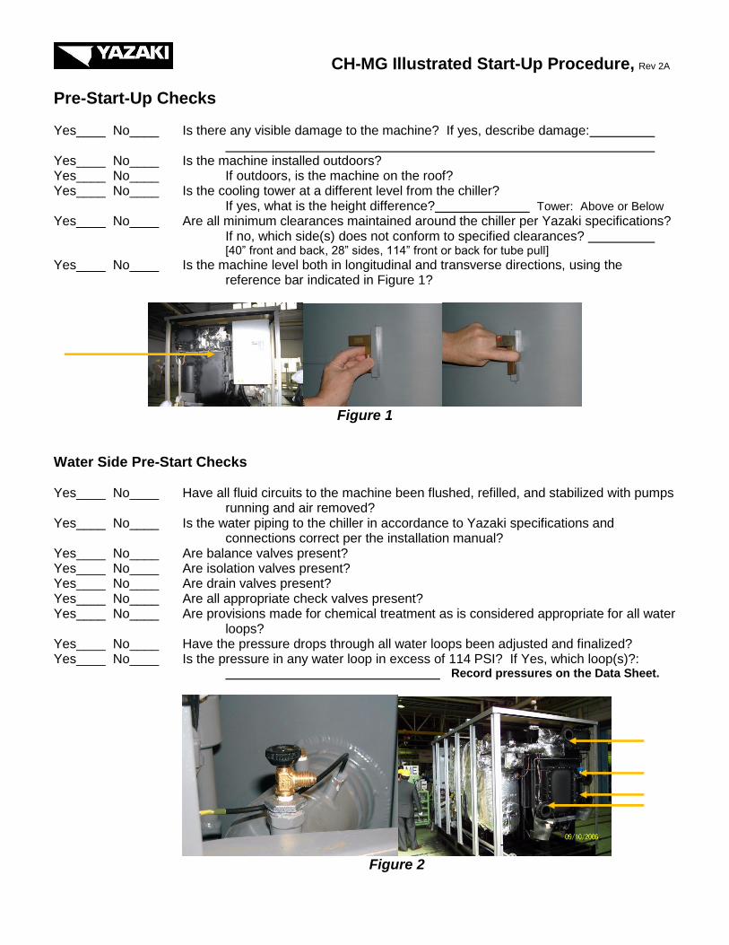
Yes____ No____ Is the machine level both in longitudinal and transverse directions, using the reference bar indicated in Figure 1?
Figure 1
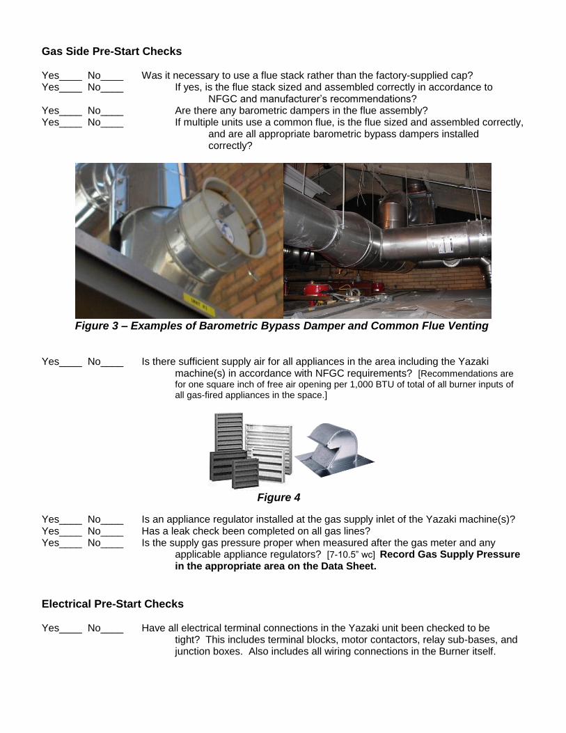
Water Side Pre-Start Checks Yes____ No____ Have all fluid circuits to the machine been flushed, refilled, and stabilized with pumps
running and air removed? Yes____ No____ Is the water piping to the chiller in accordance to Yazaki specifications and connections correct per the installation manual? Yes____ No____ Are balance valves present? Yes____ No____ Are isolation valves present? Yes____ No____ Are drain valves present? Yes____ No____ Are all appropriate check valves present? Yes____ No____ Are provisions made for chemical treatment as is considered appropriate for all water
loops? Yes____ No____ Have the pressure drops through all water loops been adjusted and finalized? Yes____ No____ Is the pressure in any water loop in excess of 114 PSI? If Yes, which loop(s)?: Record pressures on the Data Sheet.
Figure 2
Gas Side Pre-Start Checks Yes____ No____ Was it necessary to use a flue stack rather than the factory-supplied cap? Yes____ No____ If yes, is the flue stack sized and assembled correctly in accordance to NFGC and manufacturer’s recommendations? Yes____ No____ Are there any barometric dampers in the flue assembly? Yes____ No____ If multiple units use a common flue, is the flue sized and assembled correctly,
and are all appropriate barometric bypass dampers installed correctly?
Figure 3 – Examples of Barometric Bypass Damper and Common Flue Venting
Yes____ No____ Is there sufficient supply air for all appliances in the area including the Yazaki machine(s) in accordance with NFGC requirements? [Recommendations are for one square inch of free air opening per 1,000 BTU of total of all burner inputs of all gas-fired appliances in the space.]
Figure 4
Yes____ No____ Is an appliance regulator installed at the gas supply inlet of the Yazaki machine(s)? Yes____ No____ Has a leak check been completed on all gas lines? Yes____ No____ Is the supply gas pressure proper when measured after the gas meter and any
applicable appliance regulators? [7-10.5” wc] Record Gas Supply Pressure in the appropriate area on the Data Sheet.
Electrical Pre-Start Checks Yes____ No____ Have all electrical terminal connections in the Yazaki unit been checked to be tight? This includes terminal blocks, motor contactors, relay sub-bases, and
junction boxes. Also includes all wiring connections in the Burner itself.
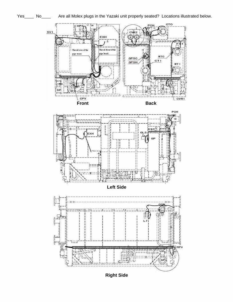
Yes____ No____ Are all Molex plugs in the Yazaki unit properly seated? Locations illustrated below.
Front Back
Left Side
Right Side
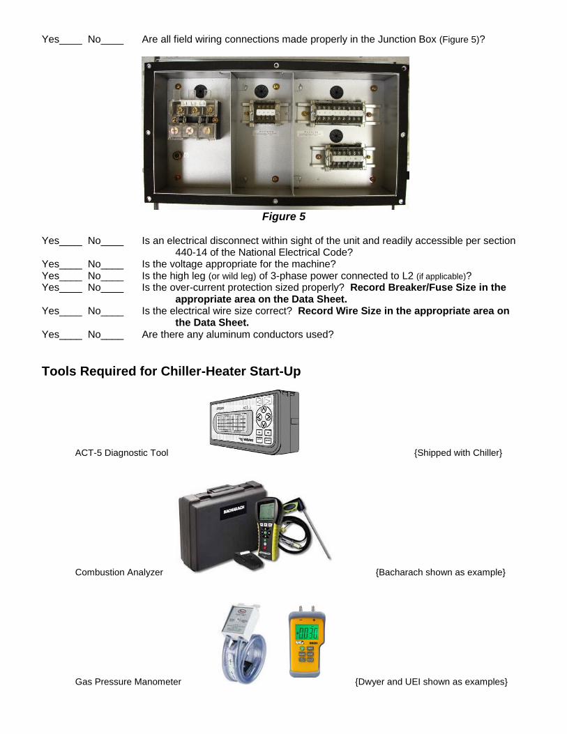
Yes____ No____ Are all field wiring connections made properly in the Junction Box (Figure 5)?
Figure 5
Yes____ No____ Is an electrical disconnect within sight of the unit and readily accessible per section 440-14 of the National Electrical Code? Yes____ No____ Is the voltage appropriate for the machine? Yes____ No____ Is the high leg (or wild leg) of 3-phase power connected to L2 (if applicable)? Yes____ No____ Is the over-current protection sized properly? Record Breaker/Fuse Size in the
appropriate area on the Data Sheet. Yes____ No____ Is the electrical wire size correct? Record Wire Size in the appropriate area on
the Data Sheet. Yes____ No____ Are there any aluminum conductors used?
Tools Required for Chiller-Heater Start-Up
ACT-5 Diagnostic Tool {Shipped with Chiller}
Combustion Analyzer {Bacharach shown as example}
Gas Pressure Manometer {Dwyer and UEI shown as examples}
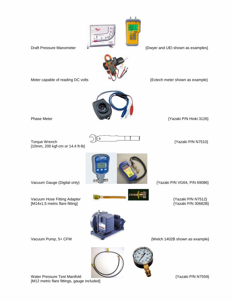
Draft Pressure Manometer {Dwyer and UEI shown as examples}
Meter capable of reading DC volts {Extech meter shown as example}
Phase Meter {Yazaki P/N Hioki 3126}
Torque Wrench {Yazaki P/N N7510} [10mm, 200 kgf-cm or 14.4 ft-lb]
Vacuum Gauge (Digital only) {Yazaki P/N VG64, P/N 69086}
Vacuum Hose Fitting Adapter {Yazaki P/N N7512} [M14x1.5 metric flare fitting] {Yazaki P/N 30682B}
Vacuum Pump, 5+ CFM {Welch 1402B shown as example}
Water Pressure Test Manifold {Yazaki P/N N7559} [M12 metric flare fittings, gauge included]
Other Recommended Tools
10’ Latex Vacuum Tubing (3/8” ID) {Yazaki P/N N7544} Calculator Permanent Marker Spirit Level {Yazaki P/N N7519} Standard Hand Tools [Screw Drivers, Pliers, Wire-Cutters, Pipe Wrenches, etc.] Tape Measure Digital or Infra-red Thermometer
Yazaki Literature Required
CH-MG Start-Up & Maintenance Data Sheet CH-MG Start-Up Procedure [this document] CH-MG150 & MG200 Installation Instructions [shipped with the chiller] Yazaki Warranty Registration Card [shipped with the chiller]
Other Yazaki Support Literature
CH-MG150 & MG200 Operating Instructions [shipped with the chiller] CH-MG Service Manual
Illustrated Start-Up Procedures for CH-MG Series with Riello Burners
Before beginning the Start-Up Procedure, please read this complete procedure, including Burner Setup and Completing Setup sections. The steps outlined here are intended to help provide the shortest possible time investment in a proper startup of a Yazaki CH-MG Chiller/Heater. There are other methods and procedures for start-up that may be equally valid, but do not mix procedures. If a different valid start-up procedure is chosen, follow only the steps of that procedure. Some steps below are listed as “Optional.” While this data is neither critical nor required for a proper startup, more complete data often assists with future inquiries in regard to maintenance and troubleshooting. IMPORTANT: On power up, the unit goes through several self-test functions and can take several minutes before it begins to respond to commands. Patience is key while setting up a CH-MG unit.
1. Record Project, ASP information, and machine data into the proper spaces at the top of the Data Sheet. Indicate this work as a Start-Up by checking the box under Type of Service on the Data Sheet.
2. Make certain the Main Gas Stop Valve, Leak Check Stop Valve, and Pilot Stop Valve are
all closed. Press the manual reset button on the Gas Pressure Switch(es). 3. Perform initial evacuation.
a. Refer to the Service Manual for proper procedures of evacuation. A general description of the evacuation setup is provided in Figure 6.
i. Record final vacuum level achieved on the Data Sheet. b. Record amount of non-condensable gases removed on the Data Sheet (optional).
c. Check for presence of hydrogen gas (optional). i. Record whether or not hydrogen gas was present on the Data Sheet.
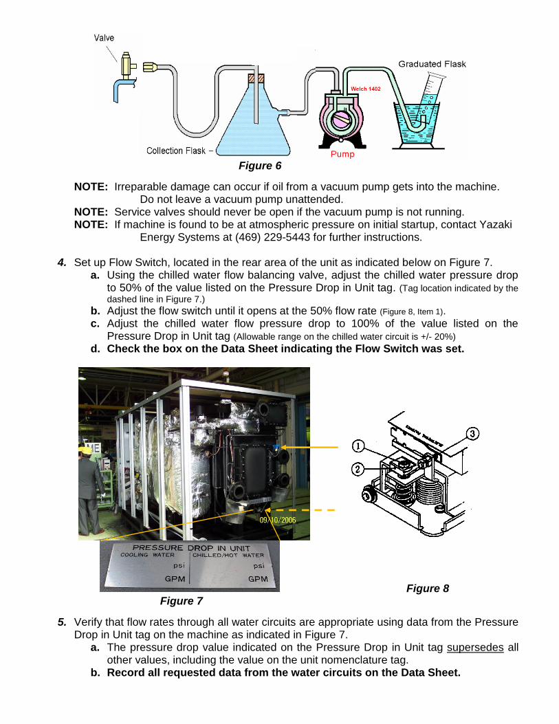
Figure 6
NOTE: Irreparable damage can occur if oil from a vacuum pump gets into the machine. Do not leave a vacuum pump unattended.
NOTE: Service valves should never be open if the vacuum pump is not running. NOTE: If machine is found to be at atmospheric pressure on initial startup, contact Yazaki Energy Systems at (469) 229-5443 for further instructions.
4. Set up Flow Switch, located in the rear area of the unit as indicated below on Figure 7.
a. Using the chilled water flow balancing valve, adjust the chilled water pressure drop to 50% of the value listed on the Pressure Drop in Unit tag. (Tag location indicated by the
dashed line in Figure 7.) b. Adjust the flow switch until it opens at the 50% flow rate (Figure 8, Item 1). c. Adjust the chilled water flow pressure drop to 100% of the value listed on the
Pressure Drop in Unit tag (Allowable range on the chilled water circuit is +/- 20%) d. Check the box on the Data Sheet indicating the Flow Switch was set.
Figure 8
Figure 7
5. Verify that flow rates through all water circuits are appropriate using data from the Pressure Drop in Unit tag on the machine as indicated in Figure 7.
a. The pressure drop value indicated on the Pressure Drop in Unit tag supersedes all other values, including the value on the unit nomenclature tag.
b. Record all requested data from the water circuits on the Data Sheet.
6. Calculate water flow and record the information on the Data Sheet (optional). 7. Check the draft pressure in the vent assembly, unless using the factory-supplied cap.
a. Attach adapter for the Draft Gauge to vent discharge. b. Adjust the barometric bypass damper to bring the draft pressure into the allowable
range of 0.00” to -0.05” wc. c. Record the Stack Draft in the appropriate area of the Data Sheet.
8. Prepare test tools and instruments.
a. Plug the ACT-5 tool into the control board. b. Attach Combustion Analyzer to the flue stack (or have it ready). c. Gas pressures will be tested at several test ports on the gas train during the Start-Up
procedure. Have tools ready and access clear to each test port.
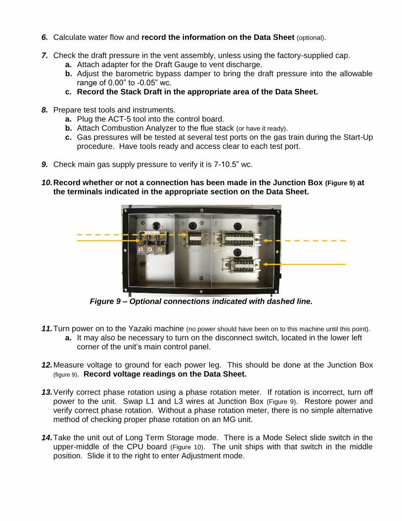
9. Check main gas supply pressure to verify it is 7-10.5” wc. 10. Record whether or not a connection has been made in the Junction Box (Figure 9) at
the terminals indicated in the appropriate section on the Data Sheet.
Figure 9 – Optional connections indicated with dashed line.
11. Turn power on to the Yazaki machine (no power should have been on to this machine until this point).
a. It may also be necessary to turn on the disconnect switch, located in the lower left corner of the unit’s main control panel.
12. Measure voltage to ground for each power leg. This should be done at the Junction Box
(figure 9). Record voltage readings on the Data Sheet.
13. Verify correct phase rotation using a phase rotation meter. If rotation is incorrect, turn off power to the unit. Swap L1 and L3 wires at Junction Box (Figure 9). Restore power and verify correct phase rotation. Without a phase rotation meter, there is no simple alternative method of checking proper phase rotation on an MG unit.
14. Take the unit out of Long Term Storage mode. There is a Mode Select slide switch in the
upper-middle of the CPU board (Figure 10). The unit ships with that switch in the middle position. Slide it to the right to enter Adjustment mode.
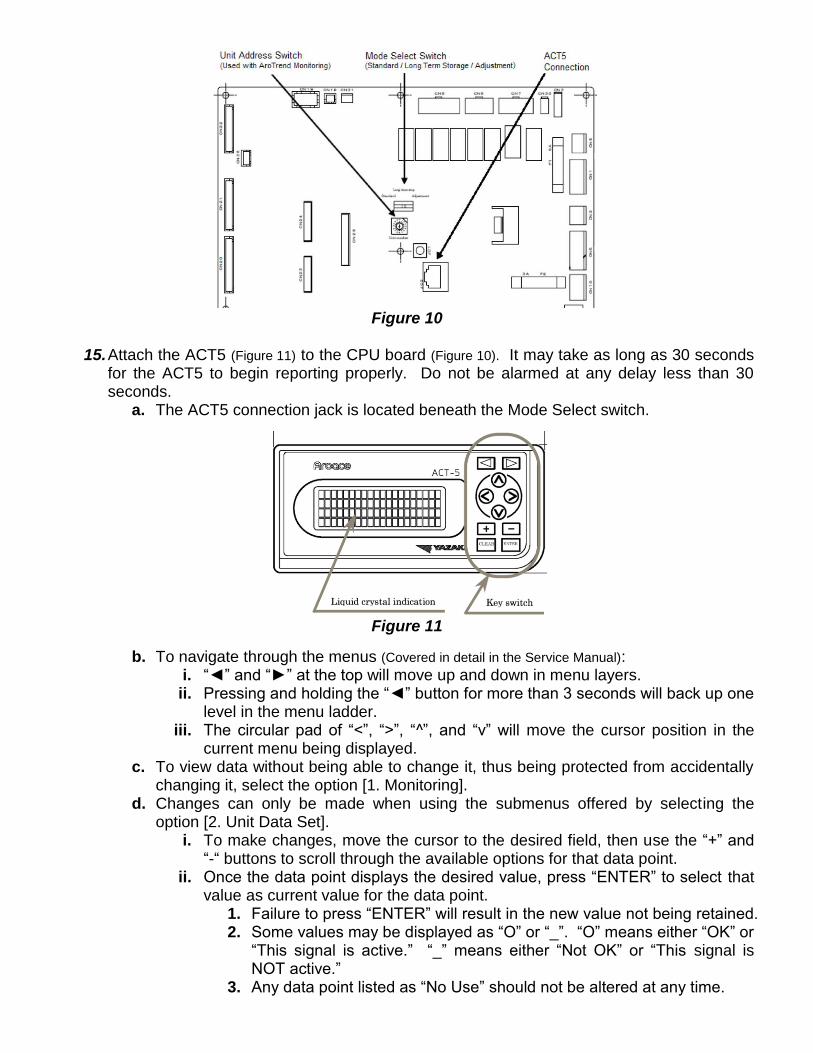
Figure 10
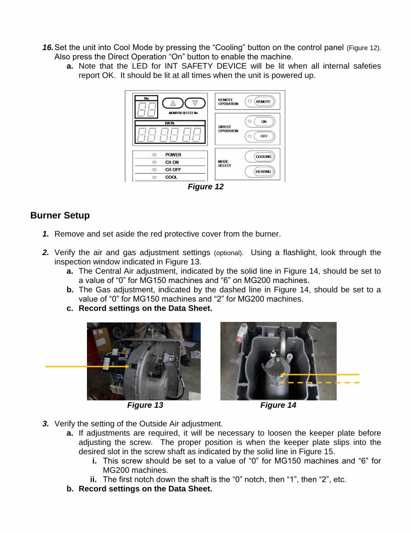
15. Attach the ACT5 (Figure 11) to the CPU board (Figure 10). It may take as long as 30 seconds
for the ACT5 to begin reporting properly. Do not be alarmed at any delay less than 30 seconds.
a. The ACT5 connection jack is located beneath the Mode Select switch.
Figure 11
b. To navigate through the menus (Covered in detail in the Service Manual): i. “◄” and “►” at the top will move up and down in menu layers. ii. Pressing and holding the “◄” button for more than 3 seconds will back up one
level in the menu ladder. iii. The circular pad of “<”, “>”, “^”, and “v” will move the cursor position in the
current menu being displayed. c. To view data without being able to change it, thus being protected from accidentally
changing it, select the option [1. Monitoring]. d. Changes can only be made when using the submenus offered by selecting the
option [2. Unit Data Set]. i. To make changes, move the cursor to the desired field, then use the “+” and
“-“ buttons to scroll through the available options for that data point. ii. Once the data point displays the desired value, press “ENTER” to select that
value as current value for the data point. 1. Failure to press “ENTER” will result in the new value not being retained. 2. Some values may be displayed as “O” or “_”. “O” means either “OK” or
“This signal is active.” “_” means either “Not OK” or “This signal is NOT active.”
3. Any data point listed as “No Use” should not be altered at any time.
16. Set the unit into Cool Mode by pressing the “Cooling” button on the control panel (Figure 12).
Also press the Direct Operation “On” button to enable the machine. a. Note that the LED for INT SAFETY DEVICE will be lit when all internal safeties
report OK. It should be lit at all times when the unit is powered up.
Figure 12
Burner Setup
1. Remove and set aside the red protective cover from the burner. 2. Verify the air and gas adjustment settings (optional). Using a flashlight, look through the
inspection window indicated in Figure 13. a. The Central Air adjustment, indicated by the solid line in Figure 14, should be set to
a value of “0” for MG150 machines and “6” on MG200 machines. b. The Gas adjustment, indicated by the dashed line in Figure 14, should be set to a
value of “0” for MG150 machines and “2” for MG200 machines. c. Record settings on the Data Sheet.
Figure 13 Figure 14
3. Verify the setting of the Outside Air adjustment.
a. If adjustments are required, it will be necessary to loosen the keeper plate before adjusting the screw. The proper position is when the keeper plate slips into the desired slot in the screw shaft as indicated by the solid line in Figure 15.
i. This screw should be set to a value of “0” for MG150 machines and “6” for MG200 machines.
ii. The first notch down the shaft is the “0” notch, then “1”, then “2”, etc. b. Record settings on the Data Sheet.
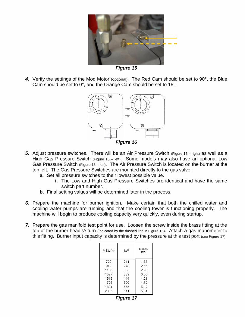
Figure 15
4. Verify the settings of the Mod Motor (optional). The Red Cam should be set to 90°, the Blue
Cam should be set to 0°, and the Orange Cam should be set to 15°.
Figure 16
5. Adjust pressure switches. There will be an Air Pressure Switch (Figure 16 – right) as well as a
High Gas Pressure Switch (Figure 16 – left). Some models may also have an optional Low Gas Pressure Switch (Figure 16 – left). The Air Pressure Switch is located on the burner at the top left. The Gas Pressure Switches are mounted directly to the gas valve.
a. Set all pressure switches to their lowest possible value. i. The Low and High Gas Pressure Switches are identical and have the same
switch part number. b. Final setting values will be determined later in the process.
6. Prepare the machine for burner ignition. Make certain that both the chilled water and
cooling water pumps are running and that the cooling tower is functioning properly. The machine will begin to produce cooling capacity very quickly, even during startup.
7. Prepare the gas manifold test point for use. Loosen the screw inside the brass fitting at the
top of the burner head ½ turn (Indicated by the dashed line in Figure 15). Attach a gas manometer to this fitting. Burner input capacity is determined by the pressure at this test port (see Figure 17).
Figure 17
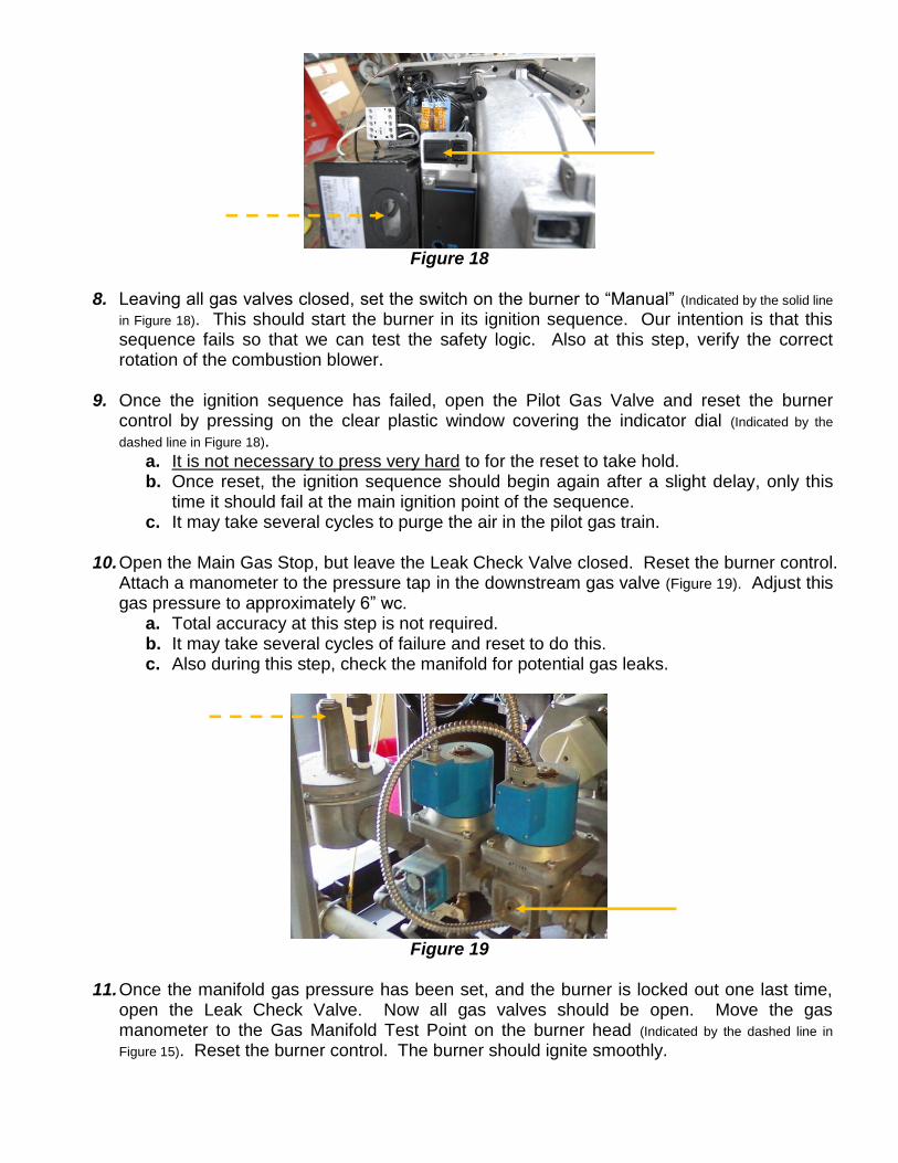
Figure 18
8. Leaving all gas valves closed, set the switch on the burner to “Manual” (Indicated by the solid line
in Figure 18). This should start the burner in its ignition sequence. Our intention is that this sequence fails so that we can test the safety logic. Also at this step, verify the correct rotation of the combustion blower.
9. Once the ignition sequence has failed, open the Pilot Gas Valve and reset the burner
control by pressing on the clear plastic window covering the indicator dial (Indicated by the
dashed line in Figure 18). a. It is not necessary to press very hard to for the reset to take hold. b. Once reset, the ignition sequence should begin again after a slight delay, only this
time it should fail at the main ignition point of the sequence. c. It may take several cycles to purge the air in the pilot gas train.
10. Open the Main Gas Stop, but leave the Leak Check Valve closed. Reset the burner control.
Attach a manometer to the pressure tap in the downstream gas valve (Figure 19). Adjust this gas pressure to approximately 6” wc.
a. Total accuracy at this step is not required. b. It may take several cycles of failure and reset to do this. c. Also during this step, check the manifold for potential gas leaks.
Figure 19
11. Once the manifold gas pressure has been set, and the burner is locked out one last time,
open the Leak Check Valve. Now all gas valves should be open. Move the gas manometer to the Gas Manifold Test Point on the burner head (Indicated by the dashed line in
Figure 15). Reset the burner control. The burner should ignite smoothly.
12. The burner will now operate at a capacity determined by manually adjusting the Mod Motor position with the “+/-“ Jog Switch, located to the right of the Auto/Manual Switch (Indicated by
the solid line in Figure 18). Intuitively, pressing “+” will increase the fire rate, and “-“ will decrease it. The first objective is to have flame stable enough to advance to the 90°, full fire position.
a. Use the ACT5 to display the temperature of the GP sensor. i. The menu path is “1.Monitoring ► A1 Analog I/O ► A11 Temperature ►
Data Point 7 GP”. b. Using the Jog Switch, open the valve until the burner sounds like it is pulsating
slightly, a sound similar to a train engine. Stop the burner at this point and monitor the GP sensor reading. Once the GP sensor indicates a temperature above 160°F, open the valve again until either the pulsating sound returns or the 90° open position is reached. If the pulsating sound returns, hold the burner there until the GP sensor reading indicates greater than 175°F. Once the GP sensor indicates above 175°F, open the valve to the 90°, full fire position. The pulsating sound should have diminished or disappeared entirely.
13. Adjust the gas pressure using the main gas pressure regulator (indicated by the dashed line in
Figure 19) so that the Gas Manifold Pressure Port (indicated by the dashed line in Figure 15) reads 4.2” wc for the MG150 machines and 5.2” wc for the MG 200 machines. This should be 100% fire rate. Record readings on the Data Sheet.
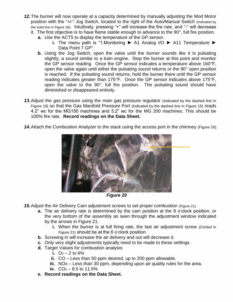
14. Attach the Combustion Analyzer to the stack using the access port in the chimney (Figure 20).
Figure 20
15. Adjust the Air Delivery Cam adjustment screws to set proper combustion (Figure 21).
a. The air delivery rate is determined by the cam position at the 6 o’clock position, or the very bottom of the assembly as seen through the adjustment window indicated by the arrows in Figure 21.
i. When the burner is at full firing rate, the last air adjustment screw (Circled in
Figure 21) should be at the 6 o’clock position. b. Screwing in will increase the air delivery and out will decrease it. c. Only very slight adjustments typically need to be made to these settings. d. Target Values for combustion analysis:
i. O2 – 2 to 6% ii. CO – Less than 50 ppm desired, up to 200 ppm allowable.
iii. NOx – Less than 30 ppm, depending upon air quality rules for the area. iv. CO2 – 8.5 to 11.5%
e. Record readings on the Data Sheet.
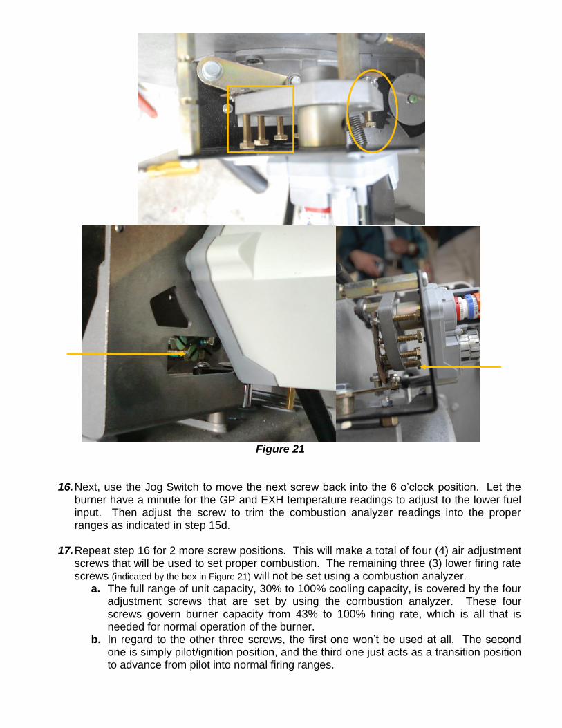
Figure 21
16. Next, use the Jog Switch to move the next screw back into the 6 o’clock position. Let the burner have a minute for the GP and EXH temperature readings to adjust to the lower fuel input. Then adjust the screw to trim the combustion analyzer readings into the proper ranges as indicated in step 15d.
17. Repeat step 16 for 2 more screw positions. This will make a total of four (4) air adjustment
screws that will be used to set proper combustion. The remaining three (3) lower firing rate screws (indicated by the box in Figure 21) will not be set using a combustion analyzer.
a. The full range of unit capacity, 30% to 100% cooling capacity, is covered by the four adjustment screws that are set by using the combustion analyzer. These four screws govern burner capacity from 43% to 100% firing rate, which is all that is needed for normal operation of the burner.
b. In regard to the other three screws, the first one won’t be used at all. The second one is simply pilot/ignition position, and the third one just acts as a transition position to advance from pilot into normal firing ranges.
i. Since the burner never spends more than 10 seconds burning the main flame in pilot position before beginning transition, and transition to the range controlled by the four screws that were adjusted by combustion analysis only takes about 5 seconds, the actual combustion analysis readings for the first three screws are not needed and trying to adjust these screws only wastes time during the startup.
ii. The goal for these three screws is to get reliable ignition and combustion with little regard toward CO or NOx readings. A slightly fuel-rich mixture for the first three screws is preferable.
1. Whatever adjustments are made in order to get a stable ignition on the second screw will need to be made to screws 3-7 as well in order for the burner flame to be able to remain stable enough to advance the burner firing rate using the Jog Switch.
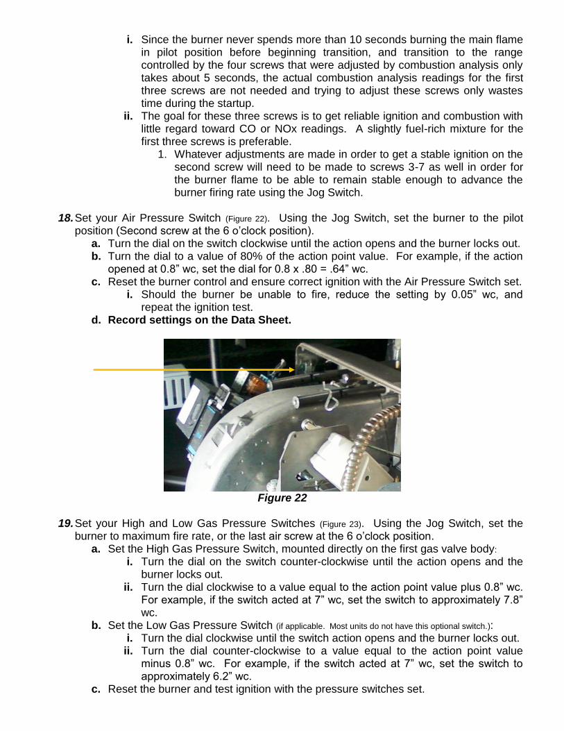
18. Set your Air Pressure Switch (Figure 22). Using the Jog Switch, set the burner to the pilot
position (Second screw at the 6 o’clock position). a. Turn the dial on the switch clockwise until the action opens and the burner locks out. b. Turn the dial to a value of 80% of the action point value. For example, if the action
opened at 0.8” wc, set the dial for 0.8 x .80 = .64” wc. c. Reset the burner control and ensure correct ignition with the Air Pressure Switch set.
i. Should the burner be unable to fire, reduce the setting by 0.05” wc, and repeat the ignition test.
d. Record settings on the Data Sheet.
Figure 22
19. Set your High and Low Gas Pressure Switches (Figure 23). Using the Jog Switch, set the
burner to maximum fire rate, or the last air screw at the 6 o’clock position. a. Set the High Gas Pressure Switch, mounted directly on the first gas valve body:
i. Turn the dial on the switch counter-clockwise until the action opens and the burner locks out.
ii. Turn the dial clockwise to a value equal to the action point value plus 0.8” wc. For example, if the switch acted at 7” wc, set the switch to approximately 7.8” wc.
b. Set the Low Gas Pressure Switch (if applicable. Most units do not have this optional switch.): i. Turn the dial clockwise until the switch action opens and the burner locks out. ii. Turn the dial counter-clockwise to a value equal to the action point value
minus 0.8” wc. For example, if the switch acted at 7” wc, set the switch to approximately 6.2” wc.
c. Reset the burner and test ignition with the pressure switches set.
i. Should the burner be unable to fire or locks out again, adjust whichever switch opened by an additional 0.4” wc. Clockwise for the High Gas Pressure Switch, counter-clockwise for the Low Gas Pressure Switch.
d. Record settings on the Data Sheet.
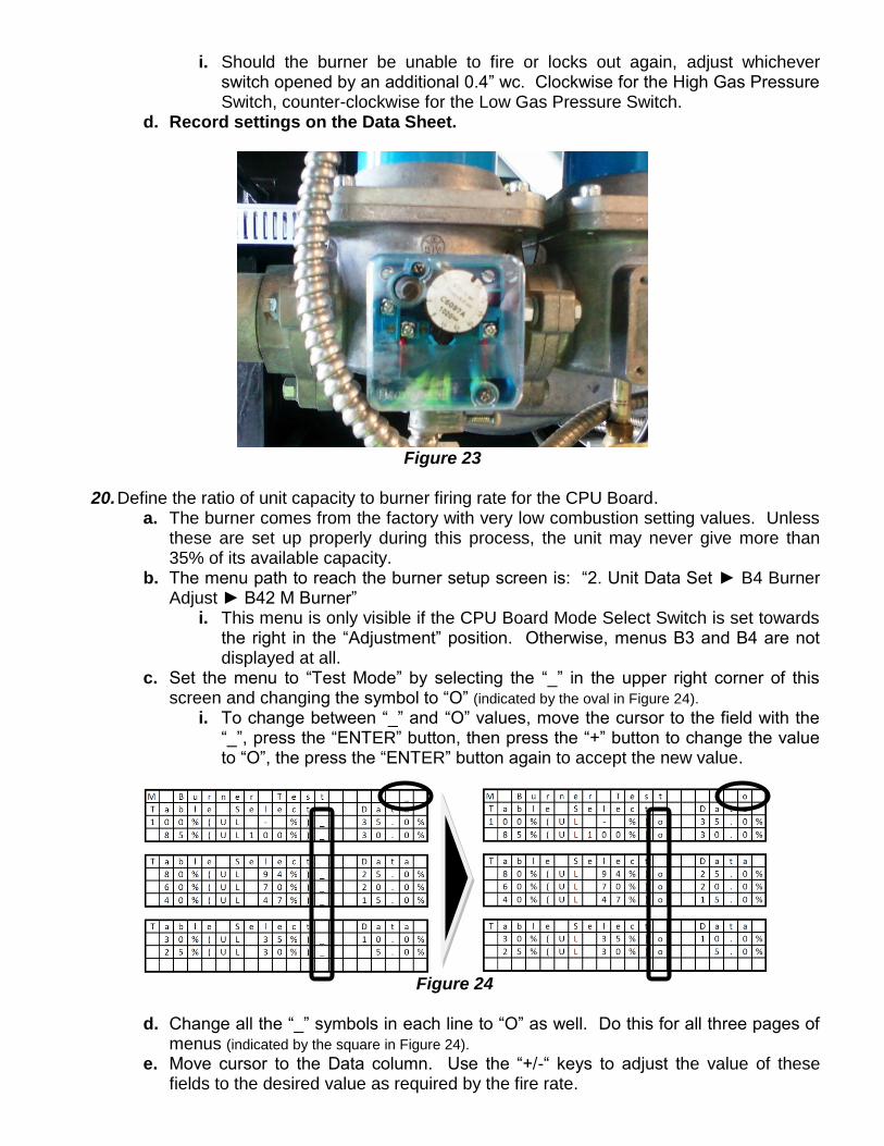
Figure 23
20. Define the ratio of unit capacity to burner firing rate for the CPU Board.
a. The burner comes from the factory with very low combustion setting values. Unless these are set up properly during this process, the unit may never give more than 35% of its available capacity.
b. The menu path to reach the burner setup screen is: “2. Unit Data Set ► B4 Burner Adjust ► B42 M Burner”
i. This menu is only visible if the CPU Board Mode Select Switch is set towards the right in the “Adjustment” position. Otherwise, menus B3 and B4 are not displayed at all.
c. Set the menu to “Test Mode” by selecting the “_” in the upper right corner of this screen and changing the symbol to “O” (indicated by the oval in Figure 24).
i. To change between “_” and “O” values, move the cursor to the field with the “_”, press the “ENTER” button, then press the “+” button to change the value to “O”, the press the “ENTER” button again to accept the new value.
Figure 24
d. Change all the “_” symbols in each line to “O” as well. Do this for all three pages of
menus (indicated by the square in Figure 24).
e. Move cursor to the Data column. Use the “+/-“ keys to adjust the value of these fields to the desired value as required by the fire rate.
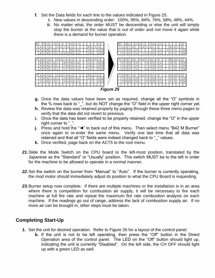
f. Set the Data fields for each line to the values indicated in Figure 25. i. New values in descending order: 100%, 95%, 84%, 76%, 58%, 48%, 44%. ii. No matter what, the order MUST be descending or else the unit will simply
stop the burner at the value that is out of order and not move it again while there is a demand for burner operation.
Figure 25
g. Once the data values have been set as required, change all the “O” symbols in
the % rows back to “_”, but do NOT change the “O” field in the upper right corner yet. h. Review the data was retained properly by paging through these three menu pages to
verify that the data did not revert to previous. i. Once the data has been verified to be properly retained, change the “O” in the upper
right corner to “_”. j. Press and hold the “◄” to back out of this menu. Then select menu “B42 M Burner”
once again to re-enter the same menu. Verify one last time that all data was retained and that all “O” fields were indeed changed back to “_” values.
k. Once verified, page back on the ACT5 to the root menu.
21. Slide the Mode Switch on the CPU board to the left-most position, translated by the Japanese as the “Standard” or “Usually” position. This switch MUST be to the left in order for the machine to be allowed to operate in a normal manner.
22. Set the switch on the burner from “Manual” to “Auto”. If the burner is currently operating, the mod motor should immediately adjust its position to what the CPU Board is requesting.
23. Burner setup now complete. If there are multiple machines or the installation is in an area
where there is competition for combustion air supply, it will be necessary to fire each machine at full fire rate and repeat the maximum fire rate combustion analysis on each machine. If the readings go out of range, address the lack of combustion supply air. If no more air can be brought in, other steps must be taken.
Completing Start-Up
1. Set the unit for desired operation. Refer to Figure 26 for a layout of the control panel. b. If the unit is not to be left operating, then press the “Off” button in the Direct
Operation area of the control panel. The LED on the “Off” button should light up, indicating the unit is currently “Disabled”. On the left side, the CH OFF should light up with a green LED as well.
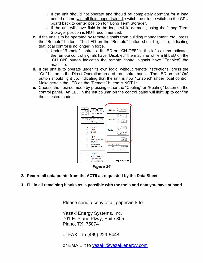
i. If the unit should not operate and should be completely dormant for a long period of time with all fluid loops drained, switch the slider switch on the CPU board back to center position for “Long Term Storage”.
ii. If the unit will have fluid in the loops while dormant, using the “Long Term Storage” position is NOT recommended.
c. If the unit is to be operated by remote signals from building management, etc., press the “Remote” button. The LED on the “Remote” button should light up, indicating that local control is no longer in force.
i. Under “Remote” control, a lit LED on “CH OFF” in the left column indicates the remote control signals have “Disabled” the machine while a lit LED on the “CH ON” button indicates the remote control signals have “Enabled” the machine.
d. If the unit is to operate under its own logic, without remote instructions, press the “On” button in the Direct Operation area of the control panel. The LED on the “On” button should light up, indicating that the unit is now “Enabled” under local control. Make certain the LED on the “Remote” button is NOT lit.
e. Choose the desired mode by pressing either the “Cooling” or “Heating” button on the control panel. An LED in the left column on the control panel will light up to confirm the selected mode.
Figure 26
2. Record all data points from the ACT5 as requested by the Data Sheet. 3. Fill in all remaining blanks as is possible with the tools and data you have at hand.
Please send a copy of all paperwork to: Yazaki Energy Systems, Inc. 701 E. Plano Pkwy, Suite 305 Plano, TX, 75074 or FAX it to (469) 229-5448 or EMAIL it to [email protected]