Pre-Installation Manual - mplusmedtech.commplusmedtech.com/123/pdf/3827.pdf · Visum™ Surgical...
48
Visum™ Surgical Lights Halogen LED • • Pre-Installation Manual 2007 1001-400-008 www.stryker.com
Transcript of Pre-Installation Manual - mplusmedtech.commplusmedtech.com/123/pdf/3827.pdf · Visum™ Surgical...

Visum™ Surgical LightsHalogenLED
••
Pre-Installation Manual
2007 1001-400-008 www.stryker.com


Visum™ Surgical Lights(Halogen & LED)
Pre-Installation Manual
Th is manual contains confi dential information that should not be disclosed or duplicated for any reason other than to use and maintain a Stryker Visum™. Th is restriction does not limit the right to use information contained in this manual, if it is obtained from another source without restriction. Th e information subject to this restriction is contained in all pages of this manual.
© 2007 Stryker Communications. All rights reserved. Information in this document is subject to change without notice. Stryker, Stryker logo, and Visum™ are registered trademarks of Stryker.
All rights reserved.
Visum™ Surgical Lights (Halogen & LED) Pre-Installation Manual
1001-400-008 REV F


Contents 5
Contents
Scope ....................................................................................................................................... 4
Warnings and Cautions ............................................................................................................ 5
Symbols ................................................................................................................................... 6
Terms ..................................................................................................................................6Guidelines and Responsibilities ............................................................................................... 7
Hospital/Contractor Responsibility ......................................................................................7Mounting Plate Descriptions .................................................................................................. 10
Mounting (Interface) Plate .................................................................................................10Universal Mounting Plate ..................................................................................................11
Visum 450 and Visum 600 (Halogen) Part Descriptions ........................................................ 12
Visum 450 & 600 (Halogen) Light Power Supply Box ......................................................12Visum 450 & Visum 600 (Halogen) Light and Camera Wall Control Panel .......................13
Visum LED Part Descriptions ................................................................................................ 14
Power Supply Box for Visum LED ....................................................................................14Power Supply Box Wall Mount (Optional) .........................................................................15Visum LED Wall Control Panel ..........................................................................................16
Site Preparation ..................................................................................................................... 17
Support Structure ..............................................................................................................17Electrical Installation .........................................................................................................20
Specifications ......................................................................................................................... 27
Environmental Specifi cations ............................................................................................27Electrical Specifi cations ....................................................................................................27Mechanical Specifi cations .................................................................................................27Critical Distances ..............................................................................................................27Support Structure Loads ..................................................................................................28Light Suspension Specifi cations .......................................................................................29
Appendix A: Seismic Calculations (Halogen Surgical Lights) ................................................ 30
Appendix B: Seismic Calculations (LED Surgical Lights) ...................................................... 42

6 Scope
Scope
Th is Pre-Installation Guide describes the requirements for assembling and installing components used in the support of Stryker ceiling-mounted surgical lighting and monitor carrying assemblies prior to installation. Th is guide covers all mechanical and electrical pre-installation requirements for the lights, control panel, and power supply. Th is guide does not describe the installation of the surgical monitors or support arm assemblies.

Warnings and Cautions 7
Warnings and Cautions
Read this guide and follow its instructions carefully. Th e words WARNING, CAUTION, and Note carry special meaning and should be carefully reviewed:
WARNING A warning indicates that the personal safety of the patient or physician may be involved. Disregarding this information could result in injury to the patient or physician.
Caution A caution indicates that there is risk of damaging the instrument.
WARNING A warning with a lightning bolt warns of hazardous voltage. All service must be performed by authorized personnel.
Note A note provides additional information, which may be useful but is not essential to complete the procedure.
To avoid serious injury to the user, patient, and/or damage to this device, adhere to the following warnings.
Use caution when lift ing heavy objects to avoid serious bodily injury or damage to equipment.
Energized electrical circuits can cause severe injury or death. Ensure that all personnel working around energized circuits have been trained in and follow proper lock-out/tag-out and other applicable safety procedures.
All Stryker-supplied equipment should be stored in a clean, dry environment prior to installation. Failing to comply with this requirement may lead to equipment damage and possible failure of life support components.
•
•
•

8 Symbols
Symbols
Denotes oxygen explosion - Oxygen forms explosive mixtures with oils, greases, and lubricants. Compressed oxygen presents an explosion hazard. Keep oxygen and gas outlets free from substances that contain oil, grease, or lubricants
Denotes compliance to CSA Standard C22.2, 60601.1 - M90
Denotes compliance to CSA Standard C22.2, 60601.1 - M90, AS 3200, IEC 60601, IEC 60601-2-41
Denotes hot surfaces
Denotes compliance to European Community Directive 93/42/EEC.
Denotes temperature limits for indicated operation or storage.
Provides usage tips and useful information
Denotes electric shock hazard
Denotes humidity limits for indicated operation or storage.
TermsInterstitial Space• The area between solid ceiling and fi nished ceiling.
HTM2007• Design considerations and Validation of Electrical Services
HBN 26• Guidelines for the design of Facilities for Surgical Procedures
HTM2022• Sign, installation, validation, and verifi cation of Medical Gas Pipeline Systems
IEC60601• Medical Electrical Equipment - General requirements for safety
IEC364• Electrical Installations of Buildings: section 710 Medical Locations
NEC• National Electrical Code
NFPA • National Fire Protection Agency (see http://www.nfpa.org)
NFPA 99• Section of NFPA relating to Health Care Facilities
OSHPD• Offi ce of Statewide Health Planning and Development (California)(see http://www.oshpd.cahwnet.gov)

Guidelines and Responsibilities 9
Guidelines and Responsibilities
Hospital/Contractor ResponsibilitySuper Structure/Mounting Support
WARNING Responsibility for proper design of the support structure lies entirely with the hospital/contractor and is not covered through warranty by Stryker. An improperly designed support structure may result in poor performance or damage to equipment and possible injury to the user. Service charges related to inadequate support structure design is at the customer’s expense.
Stryker will not review or approve customer support structures. Th is is the responsibility of the customer’s architect and designated structural engineer. Any visit by Stryker personnel to view the steelwork is only to compare its position to ceiling plans.
Design and install the support structure to:
Support (Stryker-supplied) weight and moment loads of each equipment piece. Satisfy all applicable regulations including, but not limited to, building and electrical codes.
Install the Stryker-supplied Mounting (Interface) Plate at the bottom of each support structure in accordance with the recommended method.
Loosely install (Stryker-supplied 5/8-11 UNC, M16 if provided) all thread, nuts and washers into the six (6) holes of the Mounting (Interface) Plate to avoid loss of hardware prior to installation.
Ensure that Stryker equipment and infrastructure is not impeded by the design of the support structure.
Verify that the diameter of the mounting site is 21in-22in to install the LED Surgical Light System.
Install access panels directly adjacent to each mounting point for future access for service and maintenance as described in this manual.
Delivery and StorageAccept delivery of Stryker crates and equipment to the proper room prior to the installation date.
All Stryker-supplied equipment should be stored in a clean, dry environment prior to installation. Failing to comply with this requirement may lead to damage of equipment and possible failure of life support components.
Remove and dispose of the pallets and boxes aft er completing the installation.
1.
••
2.
3.
4.
5.
6.
1.
2.

10 Guidelines and Responsibilities
Drawings and InformationTh e hospital must supply Stryker with up-to-date drawings in .dwg format (CAD) including but not limited to:
Room layout plans (current and proposed)Electrical services drawingsMechanical services drawingsElevation drawingsStructural steel (support structure) drawingsCeiling drawings
Th e hospital must ensure that Stryker is notifi ed of all revisions and changes to drawings prior to and during the scope of the project.
Electrical and Data InfrastructureInstall the Mains power, junction boxes, Ethernet drops and grounded power outlets as described in this manual, CAD drawings and applicable regulations and standards.
Provide an uninterruptible, grounded and isolated power to the surgical light system.
Install the appropriate conduit, catenaries and cable trays between mains power, surgical light power supply box, wall control panel and the support structure mounting points.
For Visum LED Lights: Install the back box for the wall-mounted Visum LED Surgical Lights application.
Provide access for all Stryker personnel to route Stryker-supplied cables from locations within each room to the termination locations, as specifi ed in the CAD drawings.
Verify the capacity of electrical infrastructure is capable of meeting the requirements as specifi ed by Stryker for the project.
Perform fi nal electrical testing and validation for all electrical cables and power outlets, including those on Stryker-supplied booms.
Note Flat Panel Only: Optional 5A in-line fuses are provided and may be installed by the electrical contractor when the fl at panel power is connected to the house power..
•
a.b.c.d.e.f.
•
1.
2.
3.
•
4.
5.
6.

Guidelines and Responsibilities 11
Stryker’s ResponsibilitiesProvide the hospital or designated contractor with CAD drawings including elevation and room confi guration drawings for Stryker-supplied equipment.
Advise the hospital of a proposed time-frame for installation of Stryker-supplied infrastructure.
Check in with hospital personnel and/or contractor to announce arrival.
Install the surgical lights and calibrate the brakes according to Stryker specifi cations.
Connect low voltage electrical and data cables for surgical lights and adjust lighting(voltage, fi eld diameter adjustments, etc.) to Stryker specifi cations.
Install the fl at panel monitor arm (if applicable) and calibrate the brakes to Stryker specifi cations.
Route and terminate all audio visual cables required for Stryker-supplied equipment.
Install fl at panel monitor (if applicable) and connect audio visual wiring kit to the fl at panel.
•
•
•
•
•
•
•
•

12 Mounting Plate Descriptions
Mounting Plate Descriptions
Mounting (Interface) PlateTh e Mounting Plate is the primary mounting component for new surgical light installations. Th e plate must be welded or bolted to the support structure by the hospital/contractor.
Figure 1: Stryker-supplied Mounting (Interface) Plate
WARNING Th e mounting plate is part of the support structure. It is the hospital’s responsibility to ensure that the mounting plate can suffi ciently support the loads defi ned for the support structure.
Note Ensure that the area inside the Clear Zone and at least one of the 2X M6 holes remain unobstructed by the support structure or weld slug.

Mounting Plate Descriptions 13
Universal Mounting PlateTh e Universal Mounting Plate adapts the hole-pattern of existing ceiling plates to accommodate Stryker equipment. At least one hole pattern in the existing mounting plate must align with one hole pattern in the Universal Mounting Plate.
For all references in this guide, the Universal Mounting Plate only adapts Stryker equipment to existing mounting plates supplied by Steris®, Berchtold® or Getinge. It is the hospital responsibility to determine whether their existing plate is compatible with the Universal Mounting Plate prior to site preparation.
WARNING Th e existing mounting plate is part of the support structure. It is the hospital’s responsibility to ensure that the existing plate is suffi ciently strong to support the loads defi ned in this manual.
Figure 2: Mounting & Universal Plate Diagram
Figure 3: Universal Mounting Plate

14 Visum 450 and 600 (Halogen) Part Descriptions
Visum 450 and Visum 600 (Halogen) Part Descriptions
Visum 450 & 600 (Halogen) Light Power Supply Box (Weight: 36.5 lbs/16.5 kg)
Th e power supply box provides 24 VDC power to the surgical lights from a 120/230 VAC source.
Mount the power supply box at the documentation station.
Note Single and dual-light confi gurations require one power supply box. Th ree or four-light confi gurations require two power supply boxes.
Use a Th ree-Bay Documentation Station to accommodate the power supply box and a SwitchPoint™ unit.
Note Th e power supply box can be confi gured with an optimal 24V inlet for battery backup, if required by the hospital.
Front View of Power Supply Box
Back View of Power Supply Box
Figure 4: Power Supply Box
1.
2.
3.

Visum 450 and 600 (Halogen) Part Descriptions 15
Visum 450 & Visum 600 (Halogen) Light and Camera Wall Control PanelTh e wall control panel provides control for lighting levels as well as control for cameras where applicable.
Vertically mount the wall control panel at conventional light switch height.
Note Single and dual-light confi gurations require one power supply box. Th ree or four-light confi gurations require two power supply boxes.
Attach the wall control panel to the three-gang box (use the provided screws).
Figure 5: Wall Control Panel
Note It is not required to install the wall control panel inside the documentation station. Consult the hospital to determine ideal placement near or in the documentation station. For proper installation of the wall control panel, a standard RACO 942 three-gang box should be mounted vertically.
1.
2.

16 Visum LED Part Descriptions
Visum LED Part Descriptions
Power Supply Box for Visum LED (Weight: 20lbs/9.09 kg)
Th e power supply box provides 24 VDC power to the surgical lights from a 120/240 VAC source.
Mount the power supply box at the documentation station or near a power outlet and Ethernet drop.
Consider spacing on the fl oor, away from walking traffi c, to accommodate the power supply box.
Note Single and dual-light confi gurations require one power supply box. Th ree or four-light confi gurations require two power supply boxes.
Use a Th ree-Bay Documentation Station to accommodate a power supply box and a SwitchPoint™ unit.
Wall Connection
Port
Expansion Port
Control Panel Mount
Light Power Panel Mount
Control Panel Mount
Light Power Panel Mount
SORN Port
SIDNE Port
Front View
Circuit Breaker
Electrical Inlet
12.5(317.5)
7.0(177.8)
Depth 15.5 (393.7) INCHES (mm)
Back View
Figure 6: Power Supply Box & Ports (for Visum LED Surgical Lights)
1.
2.
Visum LED Part Descriptions 17
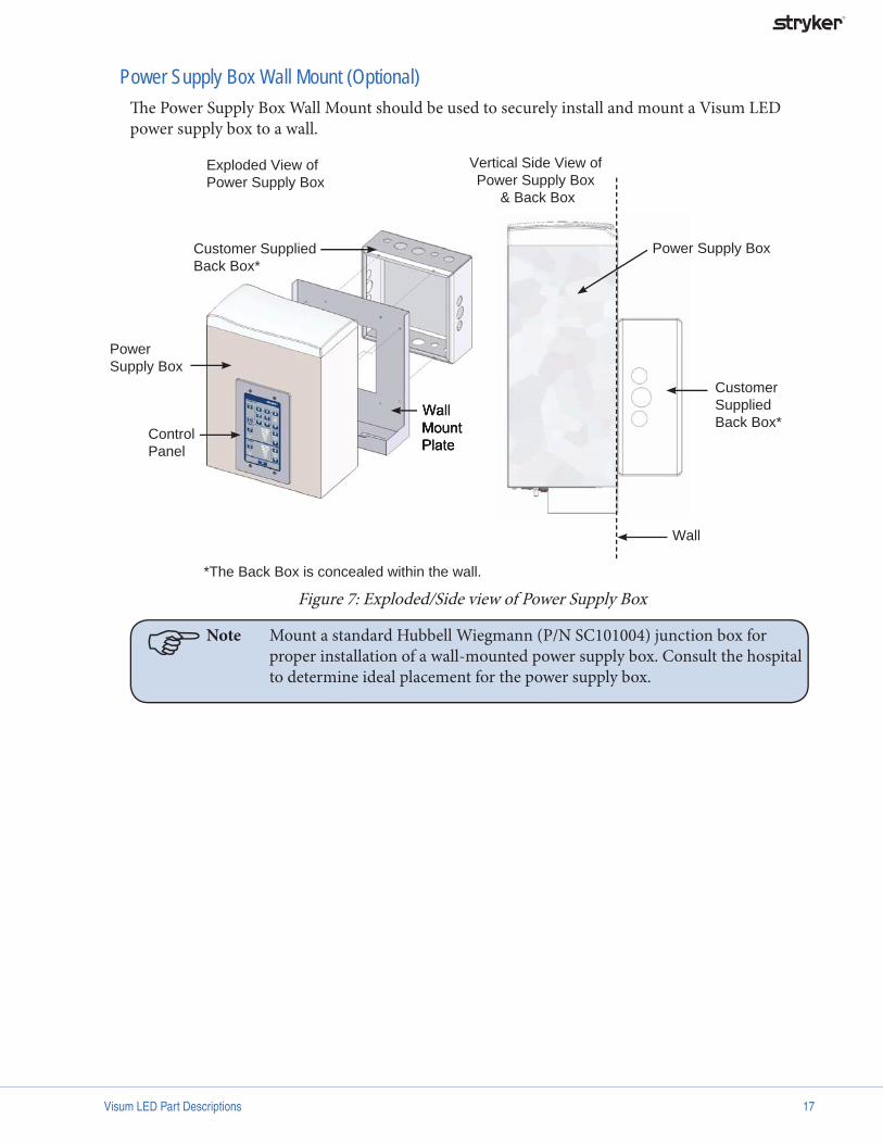
Power Supply Box Wall Mount (Optional)Th e Power Supply Box Wall Mount should be used to securely install and mount a Visum LED power supply box to a wall.
Exploded View of Power Supply Box
Wall Mount Plate
Customer Supplied Back Box*
Power Supply Box
Control Panel
Power Supply Box
CustomerSupplied Back Box*
Wall
Vertical Side View of Power Supply Box
& Back Box
*The Back Box is concealed within the wall.
Figure 7: Exploded/Side view of Power Supply Box
Note Mount a standard Hubbell Wiegmann (P/N SC101004) junction box for proper installation of a wall-mounted power supply box. Consult the hospital to determine ideal placement for the power supply box.

18 Visum LED Part Descriptions
Visum LED Wall Control PanelTh e Visum LED Wall Control Panel enables users to control light intensity as well as camera functions.
Vertically mount the panel at conventional light switch height. Th e wall control panel comes with four screws to attach the panel to a three-gang box.
Note Single and dual-light confi gurations require one power supply box. Th ree or four-light confi gurations require two power supply boxes.
Figure 8: Wall Control Panel
Site Preparation 19
Site Preparation
Installation of the support structure (as outlined in the Guidelines and Responsibilities section of this guide), electrical conduits, junctions boxes, video, data, and other services should be installed by the hospital or contractor and are not contained within the scope of work for Stryker. Stryker assumes all work has been performed in accordance with all applicable engineering and electrical building codes.
Support StructurePosition the support structure according to the room layout provided by Stryker.
WARNING Th e maximum allowed defl ection of the ceiling plate under maximum load is 1˚(1/360 deflection ratio).
Note Th e support structure must adequately support the loads specifi ed for each application. Structure designs can vary signifi cantly based on load, interstitial space, obstructions, and building codes.
Weld the Mounting (Interface) Plate to the support structure along the outer edge of the plate or use the six (.83in) holes along the outer edge of the plate to bolt it to the support structure (see Figure 1).
Do not use Stryker-supplied thread-all rods to attach the suspension to the Mounting (Interface) Plate. Th e bolts must be supplied by the contractor.
Th e Mounting (Interface) Plate must be level within 0.25in (6.4mm). Th e bottom of the mounting plate must be 2in-4in (50mm-100mm) above the fi nished ceiling. Th e space allows cables and hoses to be routed from the surgical light and Flat Panel Arm.
WARNING Caution must be exercised when lift ing heavy objects to avoid serious bodily injury or damage to equipment.
Note Dynamic (seismic) loads per California Building Code 1632A are available in Appendices A and B.
1.
2.

20 Site Preparation
Figu
re 9
: Sup
port
Str
uctu
re
Site Preparation 21
WARNING Proper design and manufacture of the support structure is the hospital and contractor’s responsibility and is not covered through warranty by Stryker. Insuffi cient structure support may result in poor performance or damage to equipment as well as injury to the user. Service charges related to inadequate structure support are the hospital’s responsibility.
WARNING Th e mounting plate is part of the support structure. It is the hospital’s responsibility to ensure that the mounting plate is suffi ciently supported to carry the loads defi ned for the support structure.
Note Th e support structure must be designed and installed to avoid obstruction of or interference with the six tapped holes [5/8-11 UNC (M16)] located adjacent to the inner diameter of the Mounting (Interface) Plate as well as the 9.06in (230mm) diameter center hole.
Note “Bolt-together,” prefabricated, structural members are highly discouraged and considered an unacceptable solution for the support structure design. Th is approach generally allows considerable fl exing of the structure resulting in poor performance and possible equipment damage.
Ceiling accessAn 18in x 18in (450mm x 450mm) minimum access panel must be installed in the ceiling within 18in (450mm) of the Mounting (Interface) Plate to allow connection of electrical and data cables during fi nal installation.
An 21in-22in (533mm-558mm) hole, either circular or square, concentric with the Mounting (Interface) Plate center is required for the light assembly installation. A 24in (600mm) diameter ceiling cover (Stryker-supplied) will conceal the hole aft er the suspension has been completely installed.
•
•
22 Site Preparation
Electrical InstallationWARNING Energized electrical circuits can cause severe injury or death. Ensure that
all personnel working around energized circuits have been trained in and follow proper lock out/tag out and other applicable safety procedures.
Note Electrical installation and components must conform to all applicable regulations.
Note All contractor-provided components must be UL-approved or UL-recognized.
Note Maximum cable lengths specifi ed in Conduit Schedules (Figures 10, 11 and 12) indicate the maximum length of cables routed through conduits. Ensure that the cable distance between the components (e.g., suspension and power supply box) does not exceed the specifi ed lengths.
Power Supply Box Mounted in Documentation StationInstall a vertically-mounted, three-gang junction box (e.g., RACO 942) for each wall control panel.
Note One and two-light configurations require one junction box; three and four-light configurations require two junction boxes.
Note It is not neccesarry to install the wall control panel inside the documentation station. Consult the hospital to determine ideal placement near or in the documentation station for the wall control panel.
Install an 18in x 18in (45cm x 45cm) back box behind the documentation station where the power supply box will be located.
(Visum LED only) Verify that an Ethernet drop is available within 72in (1.8m) of the power supply box.
Verify that a grounded, uninterruptible and isolated power outlet (110V/220V) is available wtihin 48in (1.2m) of each power supply box.
Install conduits as specifi ed in Figure 10.
Provide pull-strings and terminate all conduits with bushings.
Note All components must be located so that conduits do not exceed the maximum lengths specifi ed in Figure 10.
Note Suspensions with fl at panel monitors require additional electrical components (see Suspensions with Flat Panel Arms).
1.
2.
3.
4.
5.
6.

Site Preparation 23
Figu
re 1
0: E
lect
rical
Inst
alla
tion
with
Pow
er S
uppl
y B
ox &
Doc
umen
tatin
Sta
tion

24 Site Preparation
Wall-Mounted Power Supply Box (Visum LED only)Install an 18in x 18in (45cm x 45cm) back box behind the documentation station, if applicable.
Install a 10in x 10in x 4in Hubbell Wiegmann (P/N SC101004) junction box at the location of the power supply box.
Note The wall control panel is mounted on the power supply box for wall-mounted applications.
Provide 110V/200V, uninterruptible, grounded and isolated power to the 10in x 10in junction box.
Note The hospital must appoint an electrician to connect the power supply box to the house power.
(Visum LED only) Verify that an Ethernet drop is available within 72in (1.8m) of the documentation station.
Install the conduits as specifi ed in Figure 11.
Provide pull-strings and terminate all conduits with bushings.
Note All components must be located so that conduits do not exceed the maximum lengths specifi ed in Figure 11.
Note Suspensions with fl at panel monitors require additional electrical components (see Suspensions with Flat Panel Arms).
1.
2.
3.
4.
5.
6.

Site Preparation 25
Figu
re 1
1: E
lect
rical
Inst
alla
tion
with
Wal
l-Mou
nted
Pow
er S
uppl
y B
ox &
Doc
umen
tatio
n St
atio
n
26 Site Preparation
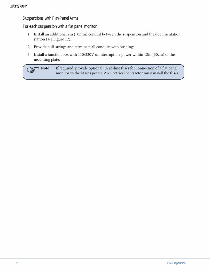
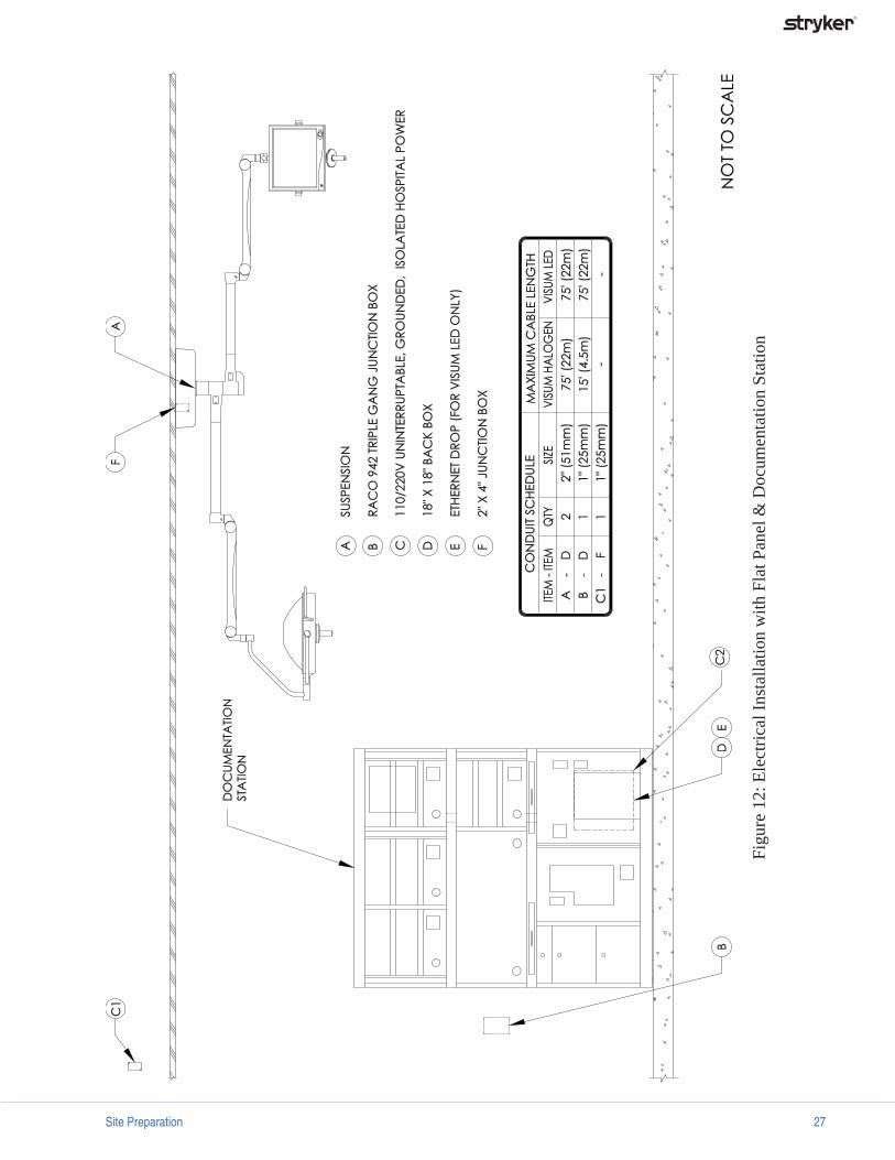
Suspensions with Flat-Panel Arms
For each suspension with a fl at panel monitor: Install an additional 2in (50mm) conduit between the suspension and the documentation station (see Figure 12).
Provide pull-strings and terminate all conduits with bushings.
Install a junction box with 110/220V uninterruptible power within 12in (30cm) of the mounting plate.
Note If required, provide optional 5A in-line fuses for connection of a fl at panel monitor to the Mains power. An electrical contractor must install the fuses.
1.
2.
3.
Site Preparation 27
Figu
re 1
2: E
lect
rical
Inst
alla
tion
with
Fla
t Pan
el &
Doc
umen
tatio
n St
atio
n

28 Site Preparation
Figu
re E
xpla
natio
n: T
wo
pow
er su
pply
box
es a
re m
ount
ed in
the
docu
men
tatio
n st
atio
n. O
ne a
dditi
onal
con
duit
is re
quire
d fo
r the
fl at
pan
el
susp
ensio
n an
d tw
o ve
rtic
ally
-mou
nted
junc
tion
boxe
s are
requ
ired
for t
wo
wal
l con
trol
pan
els.
Figu
re 1
3: E
lect
rical
Inst
alla
tion
for T
wo-
Susp
ensi
on C
onfi g
urat
ion
Specifications 29
Specifications
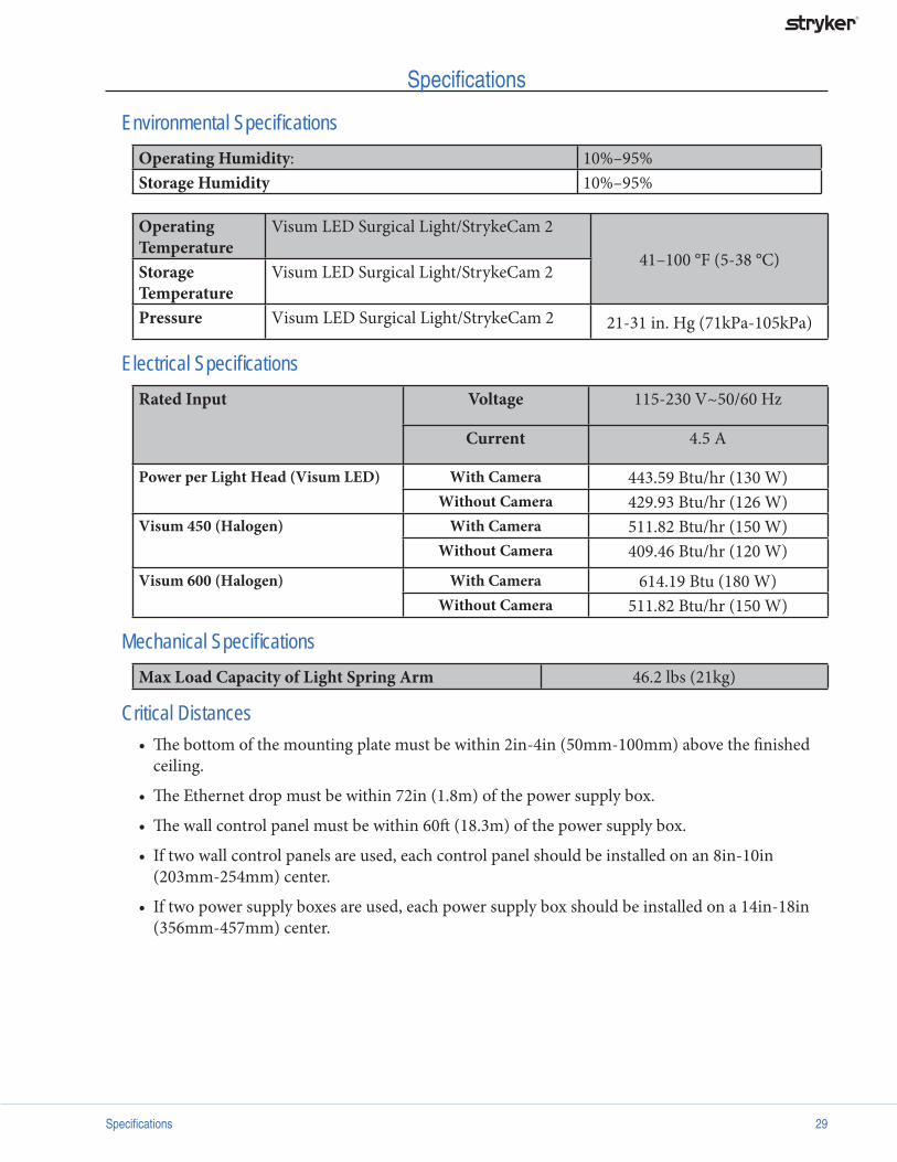
Environmental Specifi cationsOperating Humidity: 10%–95%Storage Humidity 10%–95%
Operating Temperature
Visum LED Surgical Light/StrykeCam 2
41–100 °F (5-38 °C)Storage Temperature
Visum LED Surgical Light/StrykeCam 2
Pressure Visum LED Surgical Light/StrykeCam 2 21-31 in. Hg (71kPa-105kPa)
Electrical Specifi cationsRated Input Voltage 115-230 V~50/60 Hz
Current 4.5 A
Power per Light Head (Visum LED) With Camera 443.59 Btu/hr (130 W)Without Camera 429.93 Btu/hr (126 W)
Visum 450 (Halogen) With Camera 511.82 Btu/hr (150 W)Without Camera 409.46 Btu/hr (120 W)
Visum 600 (Halogen) With Camera 614.19 Btu (180 W)Without Camera 511.82 Btu/hr (150 W)
Mechanical Specifi cationsMax Load Capacity of Light Spring Arm 46.2 lbs (21kg)
Critical DistancesTh e bottom of the mounting plate must be within 2in-4in (50mm-100mm) above the fi nished ceiling.
Th e Ethernet drop must be within 72in (1.8m) of the power supply box.
Th e wall control panel must be within 60ft (18.3m) of the power supply box.
If two wall control panels are used, each control panel should be installed on an 8in-10in (203mm-254mm) center.
If two power supply boxes are used, each power supply box should be installed on a 14in-18in (356mm-457mm) center.
•
•
•
•
•

30 Specifications
Support Structure Loads Support Structure Loads Load Location
Equipment Suspension Weight x y
Halogen
Single 113 lbs (51 kg) 37 in (940 mm) 40 in (1016 mm)
Dual 179 lbs (81 kg) 38 in (965 mm) 40 in (1016 mm)
Triple 246 lbs (112 kg) 39 in (991 mm) 40 in (1016 mm)
LED
Single 131 lbs (59 kg) 30.1 in (765 mm) 53 in (1346 mm)
Dual 204 lbs (93 kg) 40.2 in (1021 mm) 61.6 in (1564 mm)
Triple 282 lbs (128 kg) 45.6 in (1158 mm) 65.4 in (1661 mm)
Flat Panel Arm 214 lbs (97 kg) 33 in (838 mm) 49 in (1245 mm)
Figure 14: Horizontal ( x) & Vertical ( y ) Locations of Center Mass

Specifications 31
Light Suspension Specifi cations(Visum LED only)
Figure 15: Light Suspension Specifi cations
Suspension Capacity Extension Arm LengthsVisum LED Visum Halogen
Single 31.5 in (800 mm) 39.4 in (1000 mm)
Dual 31.5 in (800 mm)36.4 in (925 mm)
39.4 in (1000 mm) 33.5 in (850 mm)
Triple 31.5 in (800 mm)36.4 in (925 mm)
41.3 in (1050 mm)
39.4 in (1000 mm) 33.5 in (850 mm) 29.5 in (750 mm)

32 Appendix A
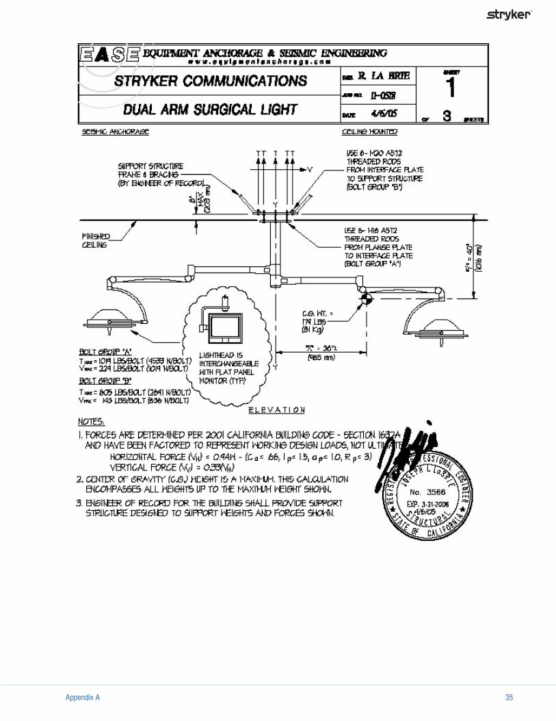
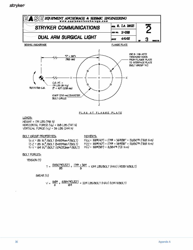
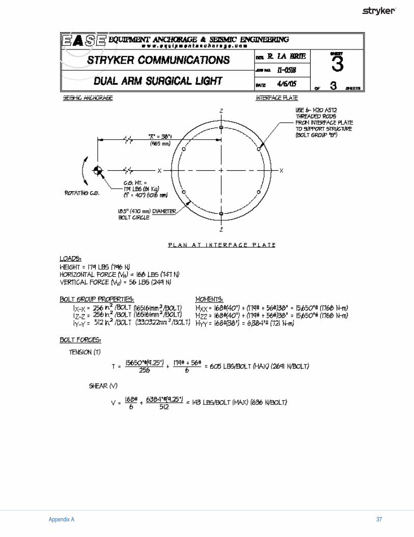
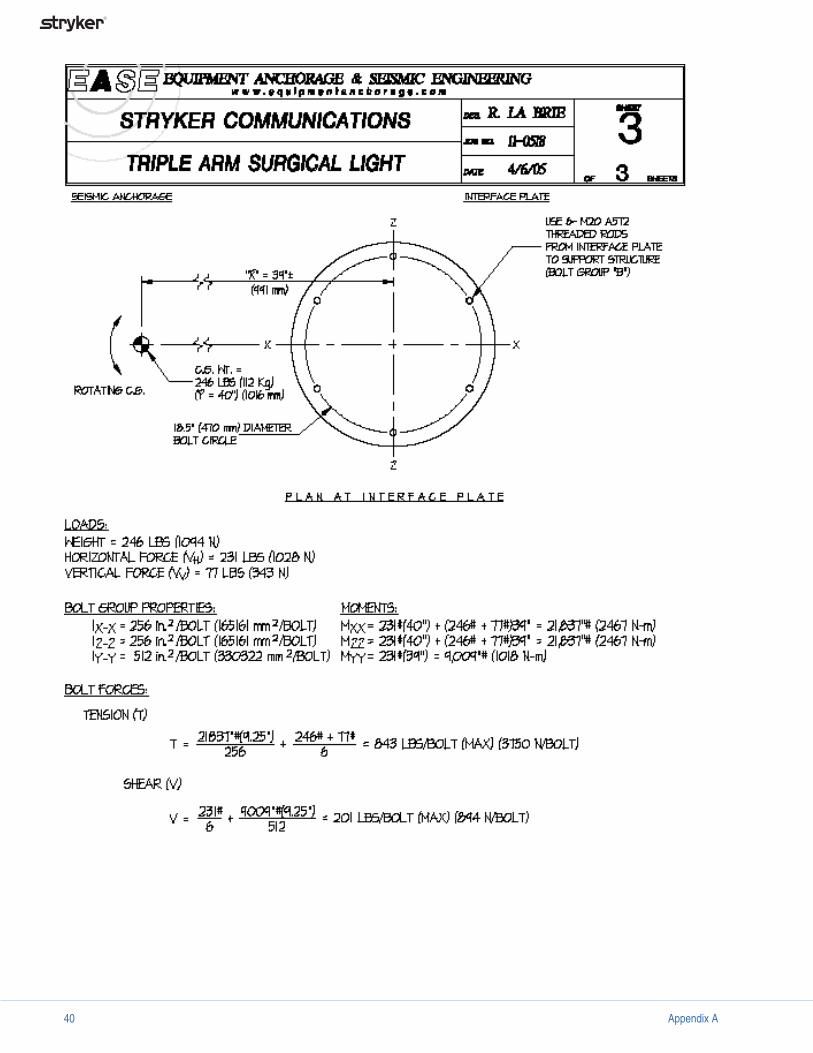
Appendix A: Seismic Calculations (Halogen Surgical Lights)

Appendix A 33

34 Appendix A
Appendix A 35
36 Appendix A
Appendix A 37

38 Appendix A

Appendix A 39
40 Appendix A

Appendix A 41

42 Appendix A

Appendix A 43
44 Appendix B
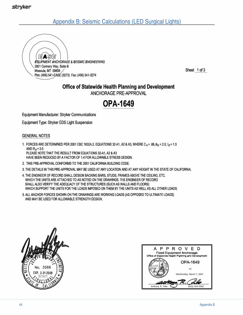
Wednesday, March 7, 2007
on
Anthony R. Pike (916) 654-3362
Appendix B: Seismic Calculations (LED Surgical Lights)

Appendix B 45
Wednesday, March 7, 2007
on
Anthony R. Pike (916) 654-3362

46 Appendix B
Wednesday, March 7, 2007
on
Anthony R. Pike (916) 654-3362


Stryker Communications
1410 Lakeside Pkwy.
Flower Mound, TX 75028
t: 972.410.7100
www.stryker.com