Pre-Installation Information CL-400 series · Section I Rev B Pre-Installation Information CL-400...
28
Section I Rev B Pre-Installation Information CL-400 series SECTION I: Introduction and Outline We are pleased to submit information pertinent to the installation of your recently purchased CINCINNATI Laser System. Included are sections that deal with the required information to efficiently put the Laser System into production. A CINCINNATI Field Service Representative will contact you shortly to schedule a pre-installation visit at your facility. We recommend that your Engineering, Maintenance, Production, and any other department expected to be involved with the Laser System review the booklet prior to the service representative contacting you. Please call CINCINNATI INCORPORATED Laser Technical Services at 513-367-7466 with any questions or suggestions. We will be pleased to help in any way possible. Additionally, we may be contacted at [email protected]. It is our sincere intent to build a solid foundation of mutual confidence, understanding, and cooperation by providing personal and written assistance with installation and start-up of this machine. To allow us to serve you in the best way possible, we ask that you review the following information prior to machine installation. SECTION OUTLINE SECTION I: Introduction and Outline Pre-Machine Arrival Checklist Pre-Start Up Checklist Service Representative Start-Up Guideline SECTION II: Foundation A. Certified Foundation Print B. Concrete Reinforcement Information C. Locating System & Components D. Environmental Factors SECTION III: Preparation Prior to Equipment Arrival A. Review of Foundation Plan B. Anchoring Preparation C. Gas Source Preparation D. Chiller Requirements E. Compressed Air Connections
Transcript of Pre-Installation Information CL-400 series · Section I Rev B Pre-Installation Information CL-400...

Section I Rev B
Pre-Installation Information CL-400 series SECTION I: Introduction and Outline
We are pleased to submit information pertinent to the installation of your recently purchased
CINCINNATI Laser System. Included are sections that deal with the required information to efficiently
put the Laser System into production.
A CINCINNATI Field Service Representative will contact you shortly to schedule a pre-installation visit at
your facility. We recommend that your Engineering, Maintenance, Production, and any other department
expected to be involved with the Laser System review the booklet prior to the service representative
contacting you. Please call CINCINNATI INCORPORATED Laser Technical Services at 513-367-7466
with any questions or suggestions. We will be pleased to help in any way possible. Additionally, we may
be contacted at [email protected].
It is our sincere intent to build a solid foundation of mutual confidence, understanding, and cooperation
by providing personal and written assistance with installation and start-up of this machine. To allow us
to serve you in the best way possible, we ask that you review the following information prior to machine
installation.
SECTION OUTLINE
SECTION I: Introduction and Outline
Pre-Machine Arrival Checklist
Pre-Start Up Checklist
Service Representative Start-Up Guideline
SECTION II: Foundation
A. Certified Foundation Print
B. Concrete Reinforcement Information
C. Locating System & Components
D. Environmental Factors
SECTION III: Preparation Prior to Equipment Arrival
A. Review of Foundation Plan
B. Anchoring Preparation
C. Gas Source Preparation
D. Chiller Requirements
E. Compressed Air Connections
Section I Rev B
F. Networking
G. Fume Collection
H. Maintenance Supplies and Spare Parts
I. Training Services
J. Documentation available at www.e-ci.com
SECTION IV: Equipment Identification
Information Showing the Machine and Its Major Components
SECTION V: Equipment Arrival
A. Inspect Equipment on Arrival for Damage
B. Equipment Unloading
C. Verify that all Equipment has arrived
SECTION VI: Equipment Preparation and Installation Suggestions
A. Preinstallation Preparation
B. Setting and Rough Leveling of Machine
SECTION VII: Equipment Service Connections
A. Input Power Requirements
B. Grounding Requirements
C. Auxiliary Equipment
D. Gas Connections – Laser Premix
E. Gas Connections – Assist Gas
Oxygen Assist Gas
Nitrogen Assist Gas
Compressed Air Assist Gas or other
F. Compressed Air Connections, general use.
G. Chiller Connection
H. Networking
SECTION VIII. Terms and Conditions:
Warranty/Service
SECTION IX: Additional Services
Section I Rev B
Pre - Machine Arrival Checklist
The customer prior to machine arrival must complete the following items:
1. Review this pre-installation document.
2. Ensure foundation meets the minimum machine requirements as shown on the foundation print.
3. Mark & drill floor for anchors. For some models holes for anchors may be drilled after machine is set in place if desired. See Section III Preparation Prior to Equipment Arrival in this document for guidelines.
4. Install proper electrical services and disconnects. See Section VII Equipment Service Connections and the foundation print for guidelines.
5. Acquire and install the necessary gas distribution systems. See Section VII Equipment Service Connections for guidelines.
6. Acquire and prepare the necessary startup fluids. See Section III of this document,
7. Prepare network connection. See section VII Equipment Service Connections, sub-section H: Networking.
Pre - Start-Up Checklist
The customer must complete the following items after the machine arrives to prepare it for the service
representative:
1. Review the packing list. (Note any damage or shortages and contact our parts department if necessary for replacements)
2. Place machine and load frame on foundation as indicated on the foundation drawing, using supplied spacers & shim packs.
3. Rough level main frame by adding / removing shims, following guidelines in Section VI Equipment preparation & Installation Suggestions of this document, and Section 2 of Operation, Safety and Maintenance Manual from web site.
4. Position & rough level load frame to align pallet rails between the frame sections. Complete anchoring.
5. Verify machine is not resting on the jacking bolts. Then tighten down on all anchor bolts to ensure that anchors do not pull out from floor by tightening. Correct any anchors that pull loose. Loosen each anchor after testing in preparation for final leveling by service representative.
6. Remove shipping materials, brackets, and lifting links, etc.
7. If applicable, place transformer(s) according to the foundation drawing. Pull the transformer wires through the transformer flex conduit provided and attach conduit to transformer and machine frame
8. Install machine ground electrode rod in floor and connect to ground bus inside machine near disconnect.
9. Run input electrical line to the rear of machine frame and attach to main disconnect. Do not apply power to the machine
10. Place chiller according to the foundation drawing.
Attach hoses provided and run through trough to the connection panel. Please see Locating System & Components in Section III, of this document regarding hose length and chiller elevation. See Chiller Connection in Section VII of this document for connection guidelines.

Section I Rev B
Pull the chiller power wires and control interface cable provided through provided seal-tite or your conduit and attach to chiller and machine frame. Chiller units with separate power drop still require wiring & seal-tite or conduit to/from machine for control interface cable. See Chiller Connection in Section VII of this document for connection guidelines. Do not apply power to the chiller.
Fill chiller through top of site tube to upper line with the proper chiller solution in accordance with Section 4 of included Operation, Safety and Maintenance Manual.
11. Route all assist gas supply piping to the connection panel on the machine frame. Blow out / clean the gas lines to remove any debris that may be present prior to connecting, Debris in the assist gas line can cause failure of the gas regulation components. Failure of components due to external contamination will not be covered by warranty.
12. Route all air supply piping to the connection panel on the machine frame, and to any external air dryer(s). See Section VII Compressed Air Connnections for connection guidelines. Blow out / clean the air lines to remove any debris that may be present prior to connecting, Debris in the air line can cause failure of components. Failure of components due to external contamination will not be covered by warranty.
13. Fit supplied rectangle duct section to fume exhaust plenum, then fit optional fan to duct section. (if ordered). Then connect exhaust ducting as needed to outdoors or customer supplied filtration unit. See Section 4 of Operation, Safety & Maintenance Manual and certified foundation plan for more information.
14. Install the optional safety mats, if applicable as shown on the foundation drawing, referencing manual EM-479,
15. Ensure adequate quantities of maintenance and spare parts. See the Consumable Parts List available on the pre-install web pages at www.e-ci.com. Order additional items as needed.
Service Representative Start Up Guideline
Refer to this section as a general list of what will happen when, to help you plan what needs to be
ready when. Of course this is a guideline only. The timing of these steps depends on many
condition and circumstances, and is subject to change. We suggest you review with your service rep
at the beginning of the installation, and as needed to best coordinate all related activities.
Day 1
1. Verify & test electrical service connections, such as main service, step down transformer (if applicable), chiller, and any electrical accessories not mounted on machine
2. Inspect chiller hose / piping connections. Verify chiller reservoir filled with proper mix.
3. Inspect / finish / test electrical connections of load frame, safety mat (if required), and control panel.
4. Verify & leak test air and gas connections.
5. Machine power up, voltage checks. . Check rotation at resonator, chiller & fume exhaust fan.
6. Attach pallet cables.
7. CNC electrical and functional test.
8. Final leveling and alignment of machine and load frame. Tighten anchors
9. Chiller warm-up [8] hours overnight (electrical service to chiller powered up for compressor

Section I Rev B
heater, but chiller not running). (completion of this step by end of first day helpful for on time completion of tasks scheduled for next day)
Day 2
1. Finish electrical checkout.
2. Resonator startup and performance checks.
Day 3
1. Beam Alignment
2. System checkout.
3. Safety system checkout.
4. Work support setup (grid shift, cut stops, etc.)
Day 4 & 5
1. Cutting tests in accordance with CINCINNATI procedures. (Material supplied by Cincinnati Inc.)
2. Machine walk through and demonstration.
3. Miscellaneous (communications, programming issues, etc.)
4. Question and answer session.
We recommend that customer personnel (operator and maintenance) actively participate in the start-up
process. This helps these individuals gain familiarity and confidence with the machine. It will also allow
questions to be answered.

Section II
SECTION II: Foundation
A. Foundation Print
A pdf file of machine’s foundation print is attached to a pre-installation e-mail sent a few days
after your machine order was logged. Please refer to this foundation print for important
detailed information throughout preparing for and installing your laser.
B. Concrete Reinforcement Information
1. The Laser System has no large dynamic loads to be contained. However, if surrounding equipment produces vibration or shock loads, the CNC Laser System may require a separate foundation to provide isolation.
2. The given foundation dimensions are minimum based on soil bearing capacity of 2,000lbs/sqft. Should there be any doubts concerning your soil condition, we recommend core drilling of the foundation area. Based on the core samplings, a Certified Civil Engineer can design a foundation that will be cost effective and substantial enough to maintain the proper support for the machine.
3. The concrete used in the foundation must be a 4,000psi quality and be properly cured prior to the setting of the machine. The number of bags of cement in the mix normally determines strength of concrete. The mix for 4,000psi is six bags per cubic yard. Curing of this concrete will normally take seven days.
4. Reinforcement of the concrete should be performed as noted on the foundation print.
5. The slab under machine is to be continuous with no cracks, no expansion joints and no saw cuts. If heavy press operations, heavy fork lift traffic, or similar is nearby, the slab under laser should be isolated from surrounding slab. The minimum permissible thickness is specified on the foundation print.
6. As a general comment concerning the CINCINNATI INCORPORATED Laser System, the four mounting points for the laser main frame and four anchor points for the loading table should be in the same plane/or at the same height. This would minimize the time required to level and shim the machine during set up. Prior to setting the machine in place, we suggest use of a transit to shoot all mounting pads and feet locations to determine the theoretical floor line. Shims should be made to bring all low points up to the theoretical floor line/level condition.
C. Locating System & Components
1. Ensure that proper maintenance access is provided to the machine, as specified in the foundation print. This also includes the area reserved to perform a “mode” burn.
2. The chiller can be moved from the location shown on the print provided the standard hose length and conduit length of 20’ will reach from machine connections to chiller connections. (approx. 5 feet is needed for ends to reach up from floor, etc. leaving approximately 15 feet available to lay in trench or on floor) Also ensure chiller location does not interfere with maintenance access and mode test shots. See Section VII of this document for location guidelines and options, including extended distance and alternate elevations (above floor level).
3. The chiller air inlet side should be a least 18” from any wall, to allow access for cleaning of air inlet filter on a regular basis (approximately weekly). It has been found that these air filters will stay cleaner longer if turned away from the cutting process, and away from any other operations that may generate dust. This side of chiller needs good access to air flow in.
4. The chiller requires adequate clearance to exhaust warm air out the top. Locating the chiller in

Section II
tight quarters may lead to warm exhaust air being “recycled”, causing the chiller to overheat.
5. Chiller may be anchored if desired, but is heavy and stable enough that anchors typically are not required. If chiller is not anchored, it can more easily be lifted by forklift for draining & other service.
6. The fume exhaust connection is typically along backside of machine. See foundation print for specific location. Allow clearance for duct run outside, or to filter system. Long duct runs and multiple turns will reduce exhaust flow, causing a dirty machine, work area, and a possible health hazard. See Section VII of this document, and Section 4 of Operation, Safety & Maintenance Manual for more information.
D. Environmental Factors
1. Air-cooled chillers, such as the chiller included with your laser system, output significant amounts of heat.
See foundation print for chiller heat output in BTU. Additional heat given off by system is minimal.
Ensure adequate airflow through chiller for proper cooling.
If your shop is air conditioned, you may consider
Alternate location of chiller, see Section VII of this document for location guidelines and options, including extended distance and alternate elevations (above floor level). Outdoor chillers are available (optional).
Ducting the exhausted heat outside during summer months. Ensure duct does not restrict airflow. Lengthy duct may require additional fans. Consult the chiller manufacturer, Dimplex Thermal, 1-800-YOU-KOOL or 269-349-6800 for technical assistance with duct size and length.
2. Minimum and maximum temperature is specified in Section 4 of Operation, Safety and Maintenance Manual.

Section III
SECTION III: Preparation Prior to Equipment Arrival
PRE-INSTALLATION REQUIREMENTS AND SUGGESTIONS.
A Review of Foundation Plan
1 CINCINNATI INCORPORATED will provide shim material equivalent to ½" per machine foot. If additional shim material will be needed for proper leveling, spacer plates should be prepared in advance.
2 Rigging equipment and/or personnel should be available to position machine. Please consult the foundation print and Section 4 of Operation, Safety & Maintenance Manual for approximate shipping weight, dimensions and clearance requirements. To ensure that no problems will arise and cause equipment delays at arrival, we recommend reviewing the following:
Size of the door opening(s)
Overhead clearances.
Plant obstructions enroute to machine foundation.
Capacity of cranes or other lifting devices.
Capacity of rigging, if used.
Internal personnel or professional riggers.
Code requirements for all services (electrical, etc.)
Location of equipment within plant to allow efficient operation and disassembly if necessary. See Section II of this document and the foundation print.
3 Determine exact location for machine, and referencing foundation print, accurately mark floor for anchor locations.
4 Proper electrical service and appropriate disconnects should be installed (see certified foundation plan). Anticipated location of the machine should be reviewed to insure that space is available to perform required maintenance and repairs if necessary. Incoming power connections should enter the machine from the floor to allow access for maintenance.
Section III
B Anchoring Preparation
Three different strategies are commonly implemented for anchoring machines, as described below. In all cases, hole drilled must be plumb (vertical), and properly located. If drilling before machine is set, center punch floor first and pilot drill floor prior to drilling full size hole to avoid drill tip walking. Always watch that drill is vertical, ask a helper to watch if necessary. Non-vertical anchor bolts can interfere with locating, setting and leveling of machine. 1 Measure, mark and drill floor accurately in accordance with foundation print. Advantages:
Quick machine set time, minimizing man-hours during rigging process. Disadvantage
Anchors must be drilled in correct spot.
Potential for drill bit “walking” off target
Main frame must be set well centered on anchors, so that anchors at far end of load frame will “line up”
2 Set machine, then drill anchor holes through machine feet. Care should be taken to center drill in machine foot hole. Try 1” PVC pipe section as bushing for drill guide. Drill hole plumb (vertical). Advantages
Quick machine set time, minimal man hours during rigging process
No chance of anchors not in correct location. Disadvantages
Time needed for drilling operations after machine set.
Load frame must be moved aside for drill clearance, and then set back. (this frame section can usually be moved with small forklift, except for 8x20 size machines)
Two enclosures would have to be removed from machine to drill thru mounting feet at resonator end of machine. This is not recommended. These two holes should be pre-drilled.
3 Position machine, ensure location satisfactory, mark anchor location on floor, then move machine and drill anchor holes.
CL-400 requires both feet at resonator end to be drilled prior to final setting of machine, partially eliminating method 2
Advantages
Allows inspection of machine location prior to drilling floor.
Eliminates potential for measuring error. Disadvantages
Requires setting machine twice.
Potential for drill bit “walking” off target still exists.
C Gas Source Preparation
Provision should be made for a safe gas cylinder rack near the machine for cylinders in use. This rack should be easily accessible for replacement of spent cylinders. See Section VII of this document for guidelines in determining types and quantities of gas cylinders needed.
Liquid cylinders for O2 assist and N2 assist may be used due to the volume of gas used for assist gasses. See Section VII of this document, and Section 4 of Operation, Safety, and Maintenance Manual for guidance).
Section III
CAUTION: The very low temperature of cryogenic gas supplies may cause hoses in the Laser
System to fail when high assist gas flow rates are used. An external vaporizer may reduce this
effect. Refer to your gas supplier for additional information. See Section VII of this document for
guidelines.
Regulators, hoses, and fittings should be acquired and prepared for connecting assist gas supply to laser system inlet port. The assist gas hoses must be high purity, medium pressure, as specified in Section VII of this document. An optional gas preparation kit is available from CINCINNATI INCORPORATED that includes all necessary regulators, hoses and fittings. This kit is available with 25 foot, 50 foot, or 75 foot hose lengths.
CAUTION: Ensure that the gas supply piping is blown out / cleaned prior to connecting piping to
machine inlet. Failure to remove debris in the gas lines may result in failure of the gas regulation
components that may not be covered by warranty.
The first laser premix gas cylinder must be certified. See Section VII of this document.
DANGER - Conventional high-pressure gas cylinders must be secured to prevent falling over. When cylinders of this type fall and break off the valve, they can rocket through concrete block walls, and other sturdy structures, and cause injury or death. See Section 3, Safety of Operation, Safety and Maintenance Manual for more information.
D Chiller Requirements
Chiller coolant mix is described in Section 4 of Operation, Safety & Maintenance Manual. The additive is specifically chosen to minimize corrosion, build up, and blockage. Problems often occur if coolant mix quality is not maintained. Repairs needed due to poor coolant quality may not be covered under warranty. To prevent clogging of cooling passages do not use automotive type anti-freeze.
Order coolant components locally, else, if needed, Dowtherm SR1 can be supplied by CI, part number 909480, in 5 gallon pails.
Chiller reservoir capacity is listed on the foundation print. Please have adequate quantities on hand. Depending on container size, a funnel and /or a pump may be needed. After the reservoir if filled the first time, additional coolant will be required during startup, as coolant will be pumped into empty hoses and passages, etc.
E Compressed Air Connections.
The machine requires a constant flow of compressed air connected to one to three inputs, depending on model and options. See Section VII of this document for guidelines and requirements.
Beam purge uses very clean dry air at high volume, moderate pressure. Additional pre-filters
and / or refrigerated dryers are sometimes required prior to the included membrane type air dryer.
Rapid pierce uses moderately clean, moderate pressure and low volume.
F Networking
The PC based controls has Windows Embedded as the operating system. See Section VII for more
networking information.

Section III
G Fume Collection
All CINCINNATI CNC Laser Systems are equipped with a fume collection plenum. CINCINNATI
INCORPORATED can supply an optional blower capable of removing typical cutting fumes.
Refer to foundation print for airflow and pressure requirements, and for flange details.
To determine the proper fume collection specifications for your installation the
supplier/contractor may need the following information.
Production rate. (Hours per day / Days per week)
Materials to be cut. (Types and thickness)
Normal material condition. (Oil, Scale, Other coatings) Cut coolant use (yes or no) (typically no longer used)
Dimensions of production room.
Location of collection unit. (Distance from machine, Type of environment)
Make up air may be needed if building is fairly airtight, to allow the optional fume fan to move
enough air volume to extract the fumes and dust created by cutting.
H Maintenance Supplies and Spare Parts
The following items are suggested as minimum stock for planned maintenance and repair
purposes. Some items listed below are listed with part numbers on Recommended Spares list at
end of this section,
1 Optic Cleaning Supplies. For the cleaning of optics the following items will be needed.
Quality lens cleaning tissue. (Tissue should not scratch or leave fiber residue when used on soft-coated surfaces).
Cleaning solvent such as ACS certified acetone or isopropyl alcohol.
Acetic acid (distilled white vinegar)
Cotton swabs and cotton balls.
Air bulb or other "Dust off device".
2 Complete set of optics.
3 Oil, filters, and seals required for maintenance intervals.
4 Calibrated power measuring device (power probe or calorimeter) for calibration measurements.
5 Cast acrylic blocks for mode evaluation.
Consult the Consumable Parts List on the pre-install web page.
I Training Services
CINCINNATI INCORPORATED provides flexible in house and on-site training services.
Contact CINCINNATI Technical Training at 513-367-7690 for details.

Section III
J Documentation on pre-install web page.
1 Operation, Safety and Maintenance Manual.
2 Programming Manuals.
3 Process Parameter Tables and/or Laser Process & Diagnostic Guide.
4 Safety Mat Installation Manual (if applicable)
5 Other option manuals as applicable.
6 NOTE: The above manuals may be sent separately.

Section IV
SECTION IV: Equipment Identification
To assist with preparation for the machine installation, review Section I & II of the Operation, Safety, and
Maintenance Manual included on our web site. The photos show the major machine components, as they
should be assembled at your facility.
Other manuals available on our web site include;
Laser Nesting Manual
A one year trial period of the laser nesting software is typically included with new machine
purchase. The manual is available on the pre-install web page.
Programming Manual
CINCINNATI Programming manuals have been incorporated into the Operation Manual (Section
7). Please use the Operation Manual to better understand programming codes (M & G codes)
macro calls, and syntax.
Process Parameters
These document includes tables listing the various machine settings for cutting different
material types, with oxygen, nitrogen, or air, up to capacity thickness.
Process Parameter and Diagnostic Guide
These document provide suggestions and guidelines for cutting various material types, and
include troubleshooting guides for cutting problems.
Safety Mat Manual
This manual is for perimeter guarding mats available only for the CL-440 in lieu of a cut area
enclosure. These mats are secured to your floor, and wired to the machine controls. Please see
this manual for installation instructions. These mats are not used on CL-460 machines, and this
manual is therefore not applicable. This manual is on the pre-install web page.
Tactile Foot Manual
This manual is for an adapter to the non-contact cutting head so that it can “track”
nonconductive materials.
Please note that the enclosed information may vary from your actual machine, depending on options
purchased with the machine.
Section V
SECTION V: Equipment Arrival
We strongly recommend that the following steps be taken upon arrival of the equipment at your facility.
A. Inspect Equipment Upon Arrival for Damage.
1. Equipment is shipped F.O.B. Whitewater, Ohio unless otherwise specified.
2. The equipment should be inspected before unloading for such things as rust due to torn shipping tarp or damage caused by movement of the machine.
3. All shock sensors should be inspected to determine if any are in a tripped condition. Find the form EP-886 taped to outside of resonator enclosure on one end of mainframe. Then inspect shock sensors and record according to this form, before lifting machine off truck, during movement, and after setting machine.
4. In the event equipment is damaged, a claim should be filed with the carrier. We suggest contacting a CINCINNATI INCORPORATED service representative for necessary estimates of repair so any required corrective actions may be undertaken before start-up. Should CINCINNATI INCORPORATED field personnel be required to investigate any damage claim, a formal purchase order from the machine owner will be required.
B. Verify that all Equipment has Arrived and is Unloaded from the Carrier.
1. Compare received equipment to the packing list.
2. In the event not all equipment was received, a claim should be filed with the carrier and CINCINNATI INCORPORATED Parts Department should be contacted so missing parts can be replaced before start-up.
C. Equipment Unloading.
It is the customer's responsibility to properly unload all equipment from the carrier including transportation or movement to final permanent location.
Refer to the lifting photographs in Section 2 of the Operation, Safety and Maintenance Manual for suggested machinery-lifting points.
Refer to Foundation Print for the machines approximate shipping weight.

Section VI
SECTION VI: Equipment Preparation and Installation Suggestions
A. Pre-Installation preparation
In order to accomplish installation and start-up of the machine in the most efficient manner, the
location and utilities should be prepared in accordance with Section III of this document prior to
machine arrival. Please refer to Section 2 of included Operation, Safety and Maintenance Manual
for installation procedures.
B. Setting & Rough Leveling of Machine.
1. The machine should be in its final position, resting directly on the spacer blocks (not on the jacking screws), anchors in place, and rough leveled.
2. Chiller fluid and deionized water ready for mixing for the chiller solution.
B. Installation of leveling shims.
1. Leveling shims should be placed between the machine mounting block and the provided spacer block as shown on the certified foundation plan.
2. The thinnest shims should always be placed between thicker shims.
3. Leveling shims should be placed so that the slot in the shim allows for clearances around the anchor bolt and the leveling screw. Ensure that the leveling screw will not come down on top of the shim.
4. Ensure that leveling shim is only under machine foot, and that other parts of the machine frame (including weld beads, etc.) are not in contact with leveling shims.
5. Ensure that all leveling screws are backed off after leveling has been completed, and that machine is resting on shim.
LEVEL HERE

Section VII
SECTION VII: Equipment Service Connections
The certified foundation print contains electrical information for full load amperage for
the machine. This information will be needed by your electrician to determine wire and
conduit sizes for the electrical supply line to the machine location. It is very important
to check local and state Electrical Codes for the proper sizing of the incoming service. If
there are no prevailing codes, Cincinnati recommends that the incoming service be sized
at a minimum of 125% of the Full Load Amps. Incoming wire sizes can be determined
from Table 310-16 in the NFPA70 section of the National Electric Code.
Please contact CINCINNATI INCORPORATED Service as to your anticipated start-up
date so that we may schedule the start-up of your machine.
A Input Power Requirements
The equipment furnished contains electronic controls which are sensitive to input power
fluctuations and high voltage transients. The main power supplied should be as "clean"
as possible to prevent control errors and increase machine reliability. Protection against
normal voltage fluctuations is built into the machine control. Limits on input power for
proper machine operations are as follows:
Supply Voltage: 460 Volts +/- 10%
Supply Frequency: 60 Hertz +/- 1%
Maximum High Voltage Limits
Amplitude 5000 volts peak-to-peak
Rise Time 500 volts per microsecond
Duration .01 seconds per transient
Frequency of Occurrence .05 seconds
If variations from these parameters do exist, or if additional information is required
please contact CINCINNATI INCORPORATED.
B Grounding Requirements
The equipment needs to be connected to ground per the National Electric Code NFPA 70, 2002
edition, article 250 sections 50 thru 70, as specified on the foundation print. The following
information expands on the requirements on the foundation print. In case of conflict, the
foundation print shall take precedence. Equipment grounding supplied by the customer for safe
and proper operation shall consist of the following:
1 GROUNDING ELECTRODE
To prevent interference from other equipment, Cincinnati Incorporated recommends a
single dedicated grounding electrode per National Electric Code NFPA 70, 2002 edition,
article 250.52 (A5).
2 RESISTANCE OF ELECTRODE TO GROUND
Section VII
The resistance to ground of the grounding electrode used should be less than 25 ohms.
Refer to National Electric Code NFPA 70, 2002 edition, article 250, and section 56, for
more information.
3 GROUNDING CONDUCTOR
A copper or aluminum grounding conductor from the earth ground to the equipment's
main panel shall be sized in accordance to the National Electric Code NFPA 70, 2002
edition, article 250.52 NOTE: To avoid ground loops, do not connect machine ground to
service g round when individual grounding electrode is used. Non-metallic conduit is
recommended
C Auxiliary Equipment
Any auxiliary equipment that will be attached to or used in conjunction with our machines must
have an R-C suppression network in parallel with each inductive load which is turned on and off
during normal operation. (Inductive loads include relay coils, solenoids, etc.)
Please contact CINCINNATI INCORPORATED if additional information is required.
D Gas Connections - Laser Gases
See Section 4 of Operation, Safety and Maintenance Manual for connection information, regulator specifications, and other details.
E Gas Connection – Assist Gas
Assist gas blows out of the nozzle tip, through the cut kerf, aiding the cutting process.
Pressure and volume needed depend on material being processed. See below for
guidelines determining these criteria. Some important notes.
Welding grade is typically adequate for assist gas.
Section 4 of Operation, Safety, and Maintenance Manual has most of the needed
connection type and max pressure information.
If cryogenic (liquid) gas sources are utilized, precautions must be taken to
prevent very cold gasses or liquid from entering the system, especially during
hi flow usage, potentially damaging system components. An appropriately
sized vaporizer will usually prevent this.
When considering assist gas source options, flow rate may be a determining
factor. For instance, most portable liquid vessels can maintain a pressure near
300 psi, but may not be able to deliver that pressure at a high flow rate over
time. High pressure cylinders will be able to deliver both high pressure and
high flow, but the quantity of gas is limited, requiring frequent cylinder
changes. A gas supplier with knowledge of high volume operation may be of
some assistance when selecting a gas source option. Please read below for
more pointers on this topic.

Section VII
Oxygen is typically used for cutting of carbon steel. Typical usage for while
cutting these applications varies from 25 SCFH to 175 SCFH, at a supply pressure
to the machine of 150 to 200 PSI (10 – 13 Bar).
Applications typically cut with oxygen
18 gauge (1.2mm) to ¼ inch (6mm) carbon steel is sometimes cut with
other gases, such as compressed air or nitrogen.
5/16” (8mm) to 1” (25mm) carbon steel is always cut with oxygen.
Portable cryogenic cylinders are often used is 20+ hours of oxygen
cutting is anticipated. Consider 12 packs for smaller run times. (If bulk
oxygen system is not already present)
In prior years oxygen was periodically used at higher pressures and
flow rates for cutting of SST or aluminum. This in not commonly done
now. If oxygen cutting of materials other than carbon steel is anticipated,
it is necessary to know how much oxygen pressure will be required, and
with which tip, then refer to table in Section 4 of Operation, Safety and
Maintenance Manual.
Oxygen Supply System usually consists of one of the following configurations.
Single high pressure cylinder with regulator is only practical if cutting
with O2 on a very limited basis (very small number of hours per week)
12 pack of high pressure cylinders with a high volume regulator that
can be set from 200 to 400 psi. These 12 packs have a low upfront cost,
but will typically only last a few shifts, and have a higher cost per cubic
foot than other systems. The 12-pack system may be a practical choice if
cutting with oxygen less than 20 hours a week.
Portable Cryogenic (Dewar) with max outlet pressure of 230 psi or
higher. An additional regulator is typically not required. If oxygen is to
be used for low pressure (<50 psi) cutting, an external vaporizer may not
be needed. Most current oxygen cutting applications use low pressures.
The 230 psi portable cryogenic system may be a practical starter system if
cutting with oxygen greater than 20 hours per week. Cryogenic systems
bleed off excess pressure when not in use.
Portable Cryogenic (Dewar) with max outlet pressure of 450 psi. An
additional regulator is typically not required. If oxygen is to be used for hi
pressure cutting (greater than 50-100 psi) an external vaporizer is
recommended. Hoses and other hardware damaged by extremely cold gas
or liquid is not covered by warranty. Most current oxygen cutting
applications do not require these hi pressures. Cryogenic systems bleed
off excess pressure when not in use.
Bulk System (outdoor tank) with a working pressure of 150 PSI,
preferably higher. Installing an oxygen bulk system for one laser is
usually not cost effective. Somewhere around two lasers, multiple shifts,
has been known to be cost effective. If bulk system already exists, supply
pressure at the machine inlet of 100+ psi might be adequate, but greater
pressure is typically needed for the regulator built into the machine to

Section VII
function properly and provide stable cutting pressure at the nozzle, even if
the commanded cutting pressure at the nozzle is only 10 psi.
Nitrogen is typically used for clean cutting of many materials. Pressure and flow
requirements vary greatly depending on application. The most demanding
applications will require a significant and costly nitrogen supply system if these
applications are to run many hours per week, so an estimate of what materials and
thickness will be cut, and many hours per day/week/month will be very helpful in
selecting a gas supply system.
Applications typically cut with nitrogen
22 gauge (0.75mm) to 1/4" inch (6mm) carbon steel
All thicknesses of Stainless Steel, up to capacity.
All thickness of Aluminum
Any combustible materials, such as plastics, etc. (Tactile adapter
option may be needed for cutting of non-metals. See manual on pre-install
web page).
Estimate nitrogen pressure and volume requirements as follows;
Determine the type and thickness of the thickest material likely to be
cut on a regular basis.
Refer to the corresponding parameter table in the Parameters document
on the pre-installation web page.
Find the cutting tip, and Optional Pressure for this material thickness.
If optional pressure is “n/a”, use cut pressure.
Find the gas volume requirement for this application in Standard Cubic
Feet per Hour (SCFH) from TABLE 4-3 Nitrogen or Air Assist Gas Flow
in Sect. 4 of Operation, Safety and Maintenance Manual. Find the tip orifice
diameter across the top of the table, and the required pressure down the
side of table.
For tip sizes up to 0.100” diameter orifice, determine the loaded*
supply pressure requirement (head pressure) needed at the machine inlet
by adding 100 PSI to the optional pressure (or cut pressure if opt pressure
is n/a) found for the chosen material thickness. For larger tip orifice
diameters, the loaded supply pressure may need to be up to double the
optional pressure. *Note: loaded pressure means the pressure the system
will provide at the specified flow rate.
Work with your gas supplier to determine the type and size nitrogen
system to meet your requirements. They will need and estimate of how
many hours per day and/or hours per week this flow and pressure will be
needed. Their capital cost for a system that will provide the required
nitrogen for the most demanding application all day, every day is
substantial.
If you have an existing nitrogen system, the above process can be
applied more or less in reverse, to determine if existing system will
provide adequate flow and pressure. Work with your gas supplier to

Section VII
determine its pressure and volume capacity. Subtract 100 PSI from its
typical operating pressure to determine the available pressure at the cutting
nozzle. Refer to the appropriate Parameters document on the pre-install web
page to determine which materials might be able to be cut at 100 psi less
than supply pressure. Then reference the tables in section 4 of the
Operation, Safety & Maintenance manual, to determine what the consumption
(flow rates) with the nozzle called for in the Parameter document. If your
gas system won’t provide the needed flow, select the next thinner material,
and recomputed to determine the pressure needed, and the flow rate, and
check again if this is within the capacity of your system. Repeat as needed
till you determine which If you anticipate cutting material thicknesses
requiring more pressure, a system upgrade may be required.
Nitrogen Supply System usually consists of one of the following configurations.
Single high pressure cylinder with regulator is only practical if cutting
with N2 on a very limited basis (less than one hour per month)
12 pack of high pressure cylinders with a high volume regulator that
can be set to 400 or more psi. These 12 packs have a low upfront cost, but
will typically only last a few hours, and have a higher cost per cubic foot
than other systems. The 12-pack system may be a practical choice if
cutting with nitrogen less than 10 hours a week.
Portable Cryogenic (Dewar) with max outlet pressure of 230 psi or
higher. An additional regulator is typically not required. If nitrogen is to
be used for moderate pressure (<50 psi) cutting, an external vaporizer
should not be needed. If this is to be used for 50 psi and greater cutting,
an external vaporizer is suggested. The 230 psi portable cryogenic system
typically will not support cutting at greater than 100 psi. Most current
nitrogen cutting applications use pressures greater than 100 psi.
Portable Cryogenic (Dewar) with max outlet pressure of 450 psi. An
additional regulator is typically not required. If oxygen is to be used for hi
pressure cutting (greater than 100 psi) an external vaporizer is
recommended. Hoses and other hardware damaged by extremely cold gas
or liquid is not covered by warranty. Most current oxygen cutting
applications do not require these hi pressures.
Bulk System (outdoor tank) with max pressure of 300-450 PSI.
Installing a nitrogen bulk system for one laser is usually not cost effective.
Somewhere around two lasers, multiple shifts, has been known to be cost
effective if cutting with nitrogen most of the time, especially so at higher
flow rates and pressures. If bulk system already exists, supply pressure at
the machine inlet of 150 psi or greater is typically needed for the regulator
built into the machine to function properly and provide stable cutting
pressure at the nozzle, even if the cutting pressure is only 10 psi.

Section VII
Compressed Air is typically used to cut faster than nitrogen, but cleaner than
oxygen, and is used for cutting thinner materials. Also see air connections below.
Bottled compressed air, or optional compressed air dryer or equivalent
is needed.
Typical supply pressure at the machine inlet of 100-150 psi is needed.
To determine if your existing pressure will be enough;
Request process parameter tables from CI Laser Tech Support
Find pressure for the material type and thickness you expect to cut.
Find supply pressure needed from air pressure Table 4-4 in Section 4 of Operation, Safety and Maintenance Manual
Assist Gas Hose: Hi purity, hi pressure hose is typically used to connect the
machine inlet to a nearby supply system, or to connect machine inlet to hard
pipe to a remote supply system. The hose must meet these specifications:
0.375” nominal ID or greater. (Larger ID recommended for lengths greater than 75 feet)
1000 PSI minimum working pressure
Plasticizer-free thermoplastic core tube (polyethylene)
Recommended hose products:
Synflex Moisture-Loc SH3440-06F Length C.I. #
25 ft. 922670
50 ft. 922671
75 ft. 922672
Parker Hannifin Parflex 540P-6
Note: Do NOT use hydrocarbon-based lubricants to assemble hose fittings. Teflon
based lubricants, including Teflon tape, should work well. Care must be taken not to
use excessive tape or lubricant, and contaminate inside of piping, which may migrate
into the machines valves and regulators, potential causing damage not covered by
warranty.
Section VII
Compressed Air Connection(s)
Compressed air connections fall into two groups.
Compressed air as a cut assist gas, which must be filtered and dried to a dew point of approximately 35F. Pressure and flow requirements are application dependent. See above section. This is connected at the assist gas connection points. Most models require an optional 3rd assist gas manual selection valve if air is to be connected while nitrogen is connected. The CL-800 series has a standard 3rd assist gas inlet, where air may be connected.
A single connection point is provided for relatively clean dry air at standard shop
pressures for beam purge, encoder purge, air blast, nozzle cooling, and other
applications. Filtering and drying is on board the machine. Pre-filtering and a
refrigeration type air dryer may be needed prior to machine inlet depending on
condition of compressed air.
The incoming compressed air temperature must be above 40°F and
cannot exceed 100°F.
Connect compressed air supply at 80 to 125 PSI depending on
dryer – Refer to addendum. The machine requires up to 780 or 980
SCFH for purge refer to addendum.
Air must not contain excessive amounts of oil or water droplets (.01 oz./hr. max.). An additional refrigerant air dryer may be required upstream from included air dryer.
Compressed air system should have a properly sized after-cooler.
Drip leg with auto drain should be used if excess oil and/or water is in the supply line. The compressed air must be free of oil droplets or vapor.
Ambient temperature must be below 100°F.
If these conditions cannot be met, additional pre-filters and/or a refrigeration type dryer
is recommended.
Refer to Section 4 of the Operation, Safety Maintenance Manual for flow and pressure
requirements.
Refer to the foundation print for connection size (1/2” nptf typical).
To maximize air dryer performance, CINCINNATI INCORPORATED recommends the
following for air supply configuration:

Section VII
To laser
Shop air
1 2
4
3
5
6 7
1 Compressor – Piston, rotary screw, rotary vane, or liquid ring compressor.
2 After cooler – Sized to bring the compressed air temperature below 100°F.
Note: After cooler and condensate separator should be installed after air receiver (#4) if compressor and air receiver are built as one unit.
3 Condensate Separator – Install condensate separator in line after the after cooler. Separator removes excess condensate from the cooling action of the after cooler. Separator must be equipped with automatic drain.
4 Air Receiver – Air line to enter the tank in the lower 1/5th of the vessel, exit at the top 1/5th. For horizontal tanks, enter the side of the tank and exit from the top.
5 Timed Solenoid Drain – Install at the bottom of air receiver and at the bottom of the air supply leg to the air dryer to remove condensate.
6 Note: Each drain line should be vented to atmosphere. Do not tie together. Ensure that the ambient temperature does not exceed 105°F.
7 Purge Gas Air Dryer – supplied by CINCINNATI INCORPORATED. Operates between 90 and 125/140 psig depending on dryer.
8 Refrigerant air dryer or moisture separator. – Installed prior to the purge gas air dryer to ensure that the air supply to the air dryer is not saturated with oil or water. This dryer may be required depending on amount of water & oil content in compressed air.
F Air Connection – optional Air Assist Gas Refrigerated Dryer connection,
Reference description of this option in Section 8 of Operation, Safety and
Maintenance Manual.
Determine airflow requirements by first finding pressure and nozzle
orifice to be used from appropriate cutting table in the Parameters
document. Then reference table “Nitrogen or Air Assist Gas Flow” in
Section 4 of Operation, Safety and Maintenance Manual
Air supply connection is typically pipe thread.
Air connection to machine is supplied. (hose)

Section VII
G Chiller Connection.
If chiller is located above floor level of machine, inline isolation valves and tee’d in drain valves are needed at machine coolant connection fittings. Without these coolant loss and equipment damage due to gravity feed &/or trapped pressure is possible, and may not be covered under warranty.
Coolant hose connections are conventional barb fittings with hose clamps (supplied) (this is typical, not guaranteed)
Standard coolant hose length is 20 feet, allowing connection end of chiller to be located approximately 15 feet from machine connection point shown on foundation print. Contact CINCINNATI Laser Technical Service or your sales rep if additional length is required.
Route coolant hoses as desired, preferably through floor trough. Keep in mind that maintenance and or service will pass through these areas many times during maintenance and / or repairs. Connect coolant supply hose from chiller outlet to machine inlet fitting. Then connect other hose from machine return fitting to chiller return fitting.
Fill chiller reservoir through top of site tube with proper proportions of coolant mix after chiller is located & connected. Coolant mix is described in Section 4 of manual. Additional coolant may be needed during start up, as empty hoses and passages are filled. Use of substandard water and / or additives can lead to corrosion, blockage of cooling passages, degradation of heat transfer properties, loss of performance, and potential down time and repairs. Repairs needed due to poor coolant quality may not be covered by warranty.
Section VII
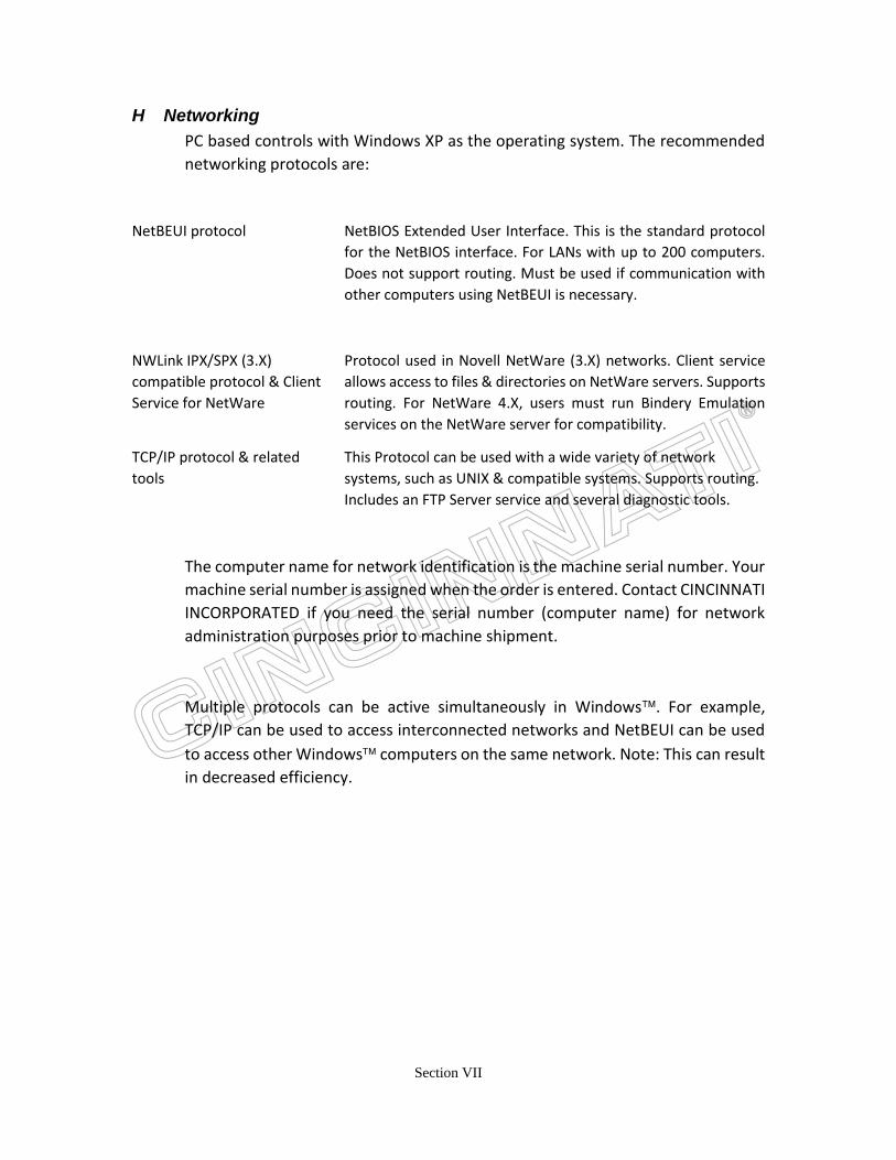
H Networking
PC based controls with Windows XP as the operating system. The recommended
networking protocols are:
NetBEUI protocol NetBIOS Extended User Interface. This is the standard protocol
for the NetBIOS interface. For LANs with up to 200 computers.
Does not support routing. Must be used if communication with
other computers using NetBEUI is necessary.
NWLink IPX/SPX (3.X)
compatible protocol & Client
Service for NetWare
Protocol used in Novell NetWare (3.X) networks. Client service
allows access to files & directories on NetWare servers. Supports
routing. For NetWare 4.X, users must run Bindery Emulation
services on the NetWare server for compatibility.
TCP/IP protocol & related
tools
This Protocol can be used with a wide variety of network
systems, such as UNIX & compatible systems. Supports routing.
Includes an FTP Server service and several diagnostic tools.
The computer name for network identification is the machine serial number. Your
machine serial number is assigned when the order is entered. Contact CINCINNATI
INCORPORATED if you need the serial number (computer name) for network
administration purposes prior to machine shipment.
Multiple protocols can be active simultaneously in Windows. For example,
TCP/IP can be used to access interconnected networks and NetBEUI can be used
to access other Windows computers on the same network. Note: This can result
in decreased efficiency.

Section VII
Cabling
The Laser System supports both Thin Ethernet and UTP network connections (only one
at a time, not simultaneously). Network cabling specifications are as follows:
Cable Type Connector Maximum
Distance
Minimum
Distance
Thin Ethernet
(Thin-net) RG-58
Coaxial
(BNC)
with Repeater
185m
no Repeater 300m
0.5 m
UTP (Unshielded
Twisted Pair)
RJ-45
100 m to hub. N/A
Special notes on cabling:
RG-58 Cable: Must conform to 10BASE-2 specifications. The cable must have 50-ohm
termination at each end, and must be grounded on one end.
Unshielded Twisted Pair (UTP) Cable: Can be 22, 24 or 26 gauge wire. Must comply with
IEEE 802.3 10BASE-T standard.
RJ-45 (8 pin) connector pin out:
(NOTE: Pins 1 and 2 must be a twisted pair, and pins 3 and
6 must be a twisted pair.)
Possible sources of UTP cable:
Number
of pairs
Manufacturer Vendor #
2 Belden 9562
4 Data Set 2404
6 Belden 9566
Function Female Pin # Male Pin #
TX+ 1 1
TX- 2 2
RX+ 3 3
4 4
5 5
RX- 6 6
7 7
8 8

Section VII
SECTION VIII: Terms and Conditions
Please refer to our Terms and Conditions document on the pre-install web page.
Section VII
SECTION IX: Additional Services
After your new CINCINNATI INCORPORATED CNC Laser System is installed and
operational, we are also prepared to become a part of your maintenance team to assist
you in keeping your Laser operating at its peak efficiency. Our Planned Maintenance
Service was developed out of the need by many customers to keep their equipment
operational with fewer problems. It provides for timely inspections, routine maintenance
on a scheduled basis, and factory expertise and backing. Please let us know if the program
would be of assistance to you. If so, we will be pleased to provide additional information
or quote a program suitable for your operation.
We recommend that a maintenance / service log be kept at the machine so that a journal
of standard maintenance procedures might be recorded. This will assist in your efforts to
track machine performance and insure that proper maintenance intervals are observed.
Additionally it will allow documentation of any problems that might arise, so those repairs
are made in a timely fashion.
To assist with this function we have included samples of Daily, Weekly, and 1000hr
(2000hr for DC-0xx slab) log sheets. These may be copied or used as a guide in the
preparation of similar documents. All of the checkpoints noted on these sheets are based
on Section 9 Maintenance & Adjustments of the Operation, Safety & Maintenance Manual or
the Laser manufacturer’s documentation.