
PRE-FEASIBILITY REPORT -...
22
Page 1 of 22 PRE-FEASIBILITY REPORT FOR Relaying and Rerouting of Petroleum Product Pipeline between IOCL, Korukkupet and IOCL Fore Shore Terminal in Railway Corridor and Port Premises at Chennai, Tamil Nadu. Submitted by: Indian Oil Corporation Limited Chennai, Tamil Nadu
Transcript of PRE-FEASIBILITY REPORT -...

Page 1 of 22
PRE-FEASIBILITY REPORT
FOR
Relaying and Rerouting of Petroleum Product Pipeline between IOCL,
Korukkupet and IOCL Fore Shore Terminal in Railway Corridor
and Port Premises at Chennai, Tamil Nadu.
Submitted by:
Indian Oil Corporation Limited
Chennai, Tamil Nadu
Page 2 of 22
CONTENTS
Sr.No. Title Page no.
1 EXECUTIVE SUMMARY
3
2 INTRODUCTION OF THE PROJECT / BACKGROUND INFORMATION
3
3 PROJECT DESCRIPTION
6
4 SITE ANALYSIS
13
5 PLANNING BRIEF
15
6 PROPOSED INFRASTRUCTURE
16
7 REHABILITATION AND RESETTLEMENT (R & R) PLAN
18
8 PROJECT SCHEDULE & COST ESTIMATES
19
9 ANALYSIS OF PROPOSAL (FINAL RECOMMENDATIONS)
20
Annexure – I : Pipeline Route Layout
Annexure - II : Schematic Diagram Indicating the Pipeline and the Railway Track
Page 3 of 22
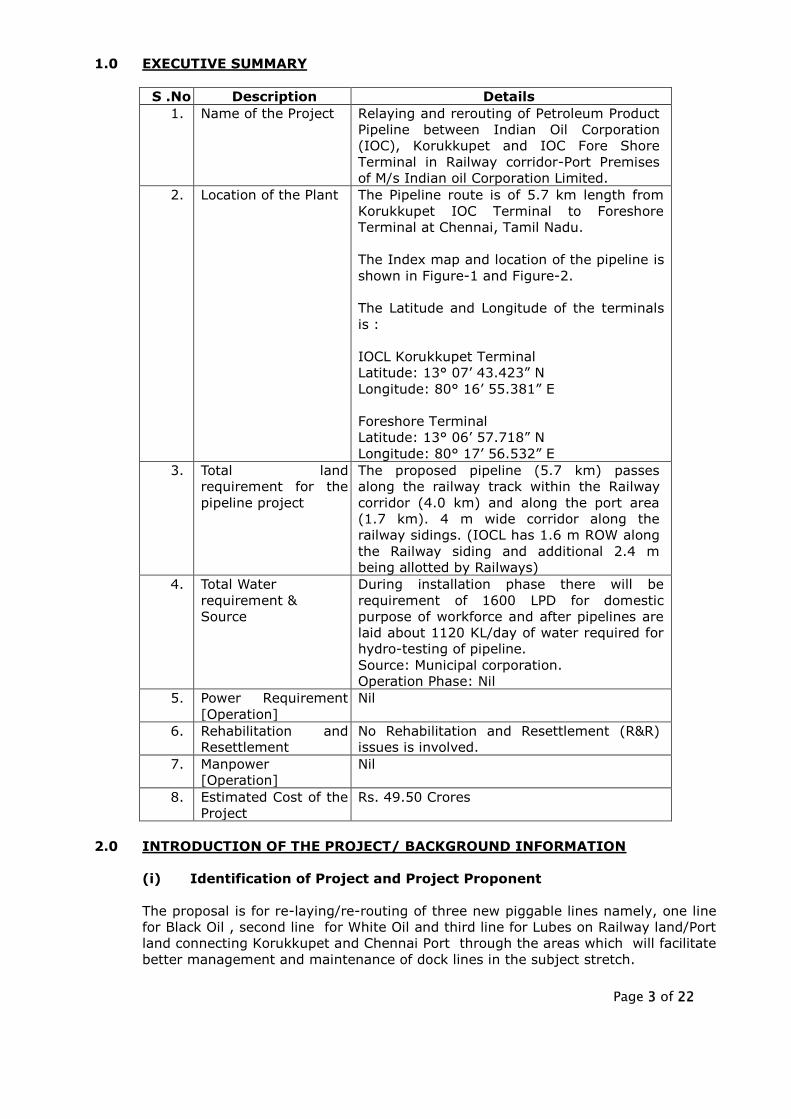
1.0 EXECUTIVE SUMMARY
S .No Description Details
1. Name of the Project Relaying and rerouting of Petroleum Product
Pipeline between Indian Oil Corporation
(IOC), Korukkupet and IOC Fore Shore
Terminal in Railway corridor-Port Premises
of M/s Indian oil Corporation Limited.
2. Location of the Plant The Pipeline route is of 5.7 km length from
Korukkupet IOC Terminal to Foreshore
Terminal at Chennai, Tamil Nadu.
The Index map and location of the pipeline is
shown in Figure-1 and Figure-2.
The Latitude and Longitude of the terminals
is :
IOCL Korukkupet Terminal
Latitude: 13° 07’ 43.423” N
Longitude: 80° 16’ 55.381” E
Foreshore Terminal
Latitude: 13° 06’ 57.718” N
Longitude: 80° 17’ 56.532” E
3. Total land
requirement for the
pipeline project
The proposed pipeline (5.7 km) passes
along the railway track within the Railway
corridor (4.0 km) and along the port area
(1.7 km). 4 m wide corridor along the
railway sidings. (IOCL has 1.6 m ROW along
the Railway siding and additional 2.4 m
being allotted by Railways)
4. Total Water
requirement &
Source
During installation phase there will be
requirement of 1600 LPD for domestic
purpose of workforce and after pipelines are
laid about 1120 KL/day of water required for
hydro-testing of pipeline.
Source: Municipal corporation.
Operation Phase: Nil
5. Power Requirement
[Operation]
Nil
6. Rehabilitation and
Resettlement
No Rehabilitation and Resettlement (R&R)
issues is involved.
7. Manpower
[Operation]
Nil
8. Estimated Cost of the
Project
Rs. 49.50 Crores
2.0 INTRODUCTION OF THE PROJECT/ BACKGROUND INFORMATION
(i) Identification of Project and Project Proponent
The proposal is for re-laying/re-routing of three new piggable lines namely, one line
for Black Oil , second line for White Oil and third line for Lubes on Railway land/Port
land connecting Korukkupet and Chennai Port through the areas which will facilitate
better management and maintenance of dock lines in the subject stretch.

Page 4 of 22
(ii) Brief description of Nature of the Project
Need for the Project and its Importance
In Chennai, there are 8 pipelines (Product and Lubes) emanating from CPCL Refinery
which passes through Tondiarpet Terminal/Tondiarpet Lube complex, Korukkupet
Terminal and FST. Out of 6 product lines starting from CPCL, the SKO and MS lines
terminates at Korukkupet terminal, ATF line terminates at Tondiarpet terminal. The
MD line - 20”, Naphtha line - 18”/16” and FO line - 14” traverses from CPCL to
Chennai Port. Also LUBE line of 12” dia starts from CPCL via LBP reaches Chennai
Port Jetty at north quay. Thus 4 lines (One MD Line, One Naphtha line, One FO line
and One Lube Line) exist across full stretch i.e. from CPCL Refinery to Chennai Port
and are also called as dock-lines. The existing pipelines and their route and length
are given in Table-1.
TABLE-1
EXISTING PIPELINE
Product / service
Size Commissioned On
From To
Length in Mts
Remarks Above ground
Under ground
White Oil / HSD
20” 1985 CPCL TNPT 1670 125
20” 1985 TNPT KKPT 2570 455
20” 1985 KKPT FST 95 3175
Major segment passing through habitations, hence proposed for replacement as single multiproduct WO line
Naptha
18” 1999 CPCL TNPT 1800 310
18” 1999 TNPT KKPT 2020 495
16” 1999 KKPT FST 900 2750
Major segment passing through habitations, hence proposed for replacement as single multiproduct WO line
White Oil / SKO
14” 1985 CPCL TNPT 1675 125
14” 1985 TNPT KKPT
1650 500
16” 1985 720 100
Motor Sprit (MS)
12” 1988 CPCL TNPT 1525 280
12” 1988 TNPT KKPT 1995 595
14” 1998 CPCL TNPT 1675 125
Black Oil / FO
14” 1998 TNPT KKPT
2680 -
16” 2002 720 100
14” 1998 KKPT FST 900 2750
Major segment passing through habitations, hence proposed for replacement
ATF 10” 1991 CPCL TNPT 1805 40
Lube Oil Line
12” 1994 CPCL LBP 800 -
12” 2001 LBP JETTY 5857 2588
Major segment passing through habitations, hence U/G Portion proposed for replacement
Out of the above, four docklines pass through congested public areas between
Korukkupet and Chennai port sector. In the stretch between Korukkupet terminal
and Chennai Port, the Black Oil, Naphtha, HSD & part of Lube lines are mostly
underground.
All the aforesaid four dock-lines were constructed as non-piggable lines. These lines
were originally laid between 1985 and 1998 and over the years across the line routes
particularly on the underground portions, habitations have come up. Over the years,

Page 5 of 22
in and around the pipeline route between Korukkupet Terminal and Foreshore
Terminal habitations have come up and road infrastructure has also developed over
the pipelines and it has become extremely difficult to have access to the
underground segments. Hence, maintenance of the underground portion of lines
between Tondiarpet R.S/Korukkupet Terminal and port entry (UG segment) have
become too difficult task. Despite line withstanding enhanced hydrotesting annually,
in case of eventuality of a minor leak, it becomes very difficult to locate and take
corrective action. It has the potential to create unsafe incidents in view of pipelines
passing underground through habitations and several stretches are below the public
roads having heavy traffic out of which some are roads plying the heavy
vehicles/containers from/to Chennai Port.
These lines were not designed and constructed as piggable and thus taking up
periodic integrity assessment study is not feasible. Hence it is proposed to replace
the UG portion of the pipeline with piggable line for safe and reliable operation.
M/s BPCL also had 3 dock lines passing through the same area through habitations in
the same topography in slightly different routes from that of IOC had to be shut off
(underground segment connecting Terminal & Port) in 2013 consequent to a PIL case
filed in National Green Tribunal Chennai (NGT) after the incident of contamination of
water in the bore well/wells near their lines.
In the same ongoing PIL case in National Green Tribunal, Chennai, MOP&NG as one
of the respondents made various short, medium and long term commitment on
behalf of OMCs. As per which, IOC will be taking action for re-routing of the
underground portion of the dock lines in the Railway corridor.
The lines are serving the vital requirement of the Nation, in meeting the
requirements of Defense/Para military, Power Sector, Railways, Transport, Major
industries and PDS besides meeting the MS/HSD demand of Tamil Nadu, Pondicherry
UT and parts of adjoining states namely Andhra Pradesh & Karnataka.
These lines are used for both export from CPCL, import and coastal positioning of
HSD during short fall in CPCL production to meet the demand of Tamil Nadu,
Pondicherry UT and parts of adjoining states namely Andhra Pradesh & Karnataka.
The naphtha line is used for evacuation of Naphtha from CPCL by way of export. The
FO line is used for positioning product at FST from CPCL for bunkering as well as for
export from Chennai port. Similar manner the Lube line is used for export from CPCL
/import of base oils as well as extracts. Thus these dock lines play a vital role in
evacuation of CPCL production and also receive through coastal movement to meet
local demand during shortfall in production /shut down period. Besides meeting the
MS/HSD demand of Public, these lines also cater to requirement of PDS, all the 3
wings of Defense, Coast Guard, Para military, Civil Aviation, Bunkering requirements
for merchant navy ships, major customers like power plants, Railways, State
Transport sectors, Fertilizer plants etc.
Taking into consideration the vital requirement of these lines on the one hand and
the challenge of lines passing through habitations on the other hand, it is proposed
to re-route the lines between IOC Korukkupet and IOC Foreshore Terminal., Chennai.
The schematic layout depicting the existing lines and the lines proposed for
replacement is enclosed as Annexure-I.

Page 6 of 22
(iii) Employment Generation (Direct & Indirect) due to the Project
For execution of the project 1 Officer in Manager Grade (D & above) is posted & 2
Officers in below Manager grade is to be posted, at site for supervision during
construction time, till completion of the project. However, for Operations no
additional manpower is required and existing manpower will be used.
3.0 PROJECT DESCRIPTION
(i) Type of project including interlinked and interdependent projects, if any.
Re-laying/re-routing of three new piggable lines namely, one line for Black Oil , second
line for White Oil and third line for Lubes on Railway land/Port land connecting
Korukkupet and Chennai Port.
The proposed pipeline is envisaged to be used for transportation of
(a) 20” dia for White Oil products MS, HSD, ATF, Naptha, SKO as a multiproduct line
(b) 14” dia for Black Oils
(c) 12” dia for Lube Oils
Location
The proposal is for re-laying/re-routing of three new piggable lines from Korukkupet
to Chennai Port, Chennai, Tamil Nadu state. The latitude and longitude of the
starting and end point of pipeline is given below.
Starting point- IOCL Korukkupet Terminal, Chennai, Tamil Nadu
Latitude: 13° 07’ 43.423” N
Longitude: 80° 16’ 55.381” E
Termination Point- Chennai Port, Chennai, Tamil Nadu
Latitude: 13° 06’ 57.718” N
Longitude: 80° 17’ 56.532” E
The index map showing the pipeline route is shown in Figure-1 and a map showing
area 10 km around both the terminals is shown in Figure-2.

Page 7 of 22
FIGURE-1
INDEX MAP SHOWING THE PIPELINE ROUTE
Received Terminal
Dispatch Terminal
IOCL Pipeline

Page 8 of 22
FIGURE-2
STUDY AREA MAP OF THE PIPELINE PROJECT
(500 M EITHER SIDE OF THE PIPELINE ROUTE)

Page 9 of 22
(ii)Details of alternate sites considered and the basis of selecting the
proposed site, particularly the environmental considerations gone into
should be highlighted.
Various options for re-routing through unhabitated areas were studied, but as the
city has grown, there is no space available for laying the above 4 lines. Therefore
Railways were approached for additional space to the extent of 4 mts width, for
laying the lines along the Railway Corridor between Korukkupet and Chennai Port
entry, where IOC already have 1.6 mts width ROW and Railways have positively
considered IOC request.
As per guidelines, in 4 mtr width, maximum 3 pipelines can only be accommodated
comfortably complying the OISD norms and accordingly, against the presently
existing 4 lines, it is proposed to lay the following 3 pipelines to meet the
requirements. The proposed pipeline is envisaged to be used for transportation of
following products.
20” dia for White Oil products MS, HSD, ATF, Naptha, SKO as a multiproduct line
14” dia for Black Oils
12” dia for Lube Oils
(iii) Size or magnitude of operation.
Products to be handled
The products to be handled in White Oil pipeline are MS, HSD, ATF, and NAPHTHA. In
Black Oil pipeline, FO, is proposed to be handled and in Lube oil pipeline, Lubes is
proposed.
Product Characteristics
The pipeline system has been designed on the basis of the following characteristics of
the products:
Pipeline
size
Product
considered
Specific gravity Kinematic viscosity in
CST
20” dia HSD 0.85 5 @ 40 deg C
14” dia FO 0.95 180@ 50 deg C
12.75” dia Lube Oil 0.88 100@ 40 deg C
Design Capacity
The pipeline has been designed considering the loading and unloading of tanker
parcels which have to be handled with optimal time and accordingly a flow rate of
1500 KL per hour for 20” W.O line, 600 KL per hour for 14” B.O lines and 200 KL per
hour for 12.75” Lube line.
The present throughput per annum are as follows
W.O products : 1.1 MMTPA
B.O products : 0.7 MMTPA
Lubes : 0.3 MMTPA

Page 10 of 22
Design Parameters
For mainline as well as station piping, a weld joint factor of 1.00 (one) has been
considered.
Maximum allowable operating pressure (MAOP) of the system is based on 50% of the
specified minimum yield strength of the pipe material.
The pipeline design is based on the API/ASME B 31.4 standards applicable for hydro
carbon pipelines.
Pipeline thickness is calculated considering the corrosion allowance, stress and surge
requirements as per the above standards using the formula below
T- thickness of pipe
S- yield strength in psi :46000 (46 grade pipe)
S.F - safety factor assumed at 50% =0.5
D- diameter of the pipeline in inch
MAOP- Maximum allowabale operating pressure
As per the pipeline operations, maximum operating pressure shall not exceed
7Kg/sq.cm, however for the calculation purpose 12 Kg/sq.cm maximum operating
pressure is considered. API 5L X46 grade pipes have been chosen. Accordingly the
thickness required and maximum allowable operating pressures for the considered
pipelines are given the Table-2.
TABLE-2
PIPELINE SPECIFICATIONS
Pipeline
dia in
inches
Thickness of
pipeline
considered
(inch)
Thickness required
for maximum
operating pressure
(inch)
Actual
operating
pressure
considered
MAOP
Kg/sq.cm
20 0.281 0.07419 12 45.45
14 0.281 0.05193 12 64.93
12.75 0.281 0.04729 12 71.29
Thus Pipes of higher wall thickness and MAOP are much higher than the required.
Further corrosion mitigation measures are implemented.
There are no water course crossings and there are only rail and road crossings. At
rail crossings, where casing pipe would be provided, the pipe wall thickness would
remain same as that for the main pipeline as per the standards. For Horizontal
Directional Drilling (HDD) technique at rail crossings, higher wall thickness pipes are
considered.
Entire relaying/re-routing is planned to be laid as underground with effective cover of
minimum 1.2 M below the ground level.

Page 11 of 22
(iv) Project description with process details
Pipeline Size Optimization
It is proposed to re-route/ lay 3 piggable lines namely one line for Black Oil, second
line for White Oil and third line for Lubes on Railway land connecting Korukkupet and
Chennai Port through the areas which will facilitate better management and
maintenance of dock lines in this stretch. These lines will pass through Railway land
from Korukkupet to Royapuram via Vannarapet RS and enter the Port area below the
ROB connecting Royapuram and Beach Stations.
Since the replacement of the pipelines is only in the stretch between Korukkupet
terminal and FST/Jetty and to ensure uniformity, piggability and achieving requisite
flow rate, it is proposed to lay pipes of the same dia as the existing ones from CPCL to
Jetty. Hence the new white oil line is proposed to be 20” W.O dia (the existing 20” dia
MD line right from Korukkupet to Jetty), the new Black oil pipeline to be 14” dia
(existing B.O line from CPCL is 14” dia from CPCL to Jetty) and the new Lube oil line is
12” dia (existing Lubeline is 12” dia from CPCL /LBP Chennai to Jetty). The details of
the proposed pipeline is given in Table-3.
TABLE-3
DETAILS OF THE PROPOSED PIPELINE
Product /
service
Size
(dia in
“inch”)
From To Length in
(M)
Remarks
A/G U/G
White Oil Line /
HSD/MS/Naptha
20” FST KKPT 500 5450 Single Line will be used
for all W.O Product. AG
portion is within
station premises.
Black Oil / FO 14” FST KKPT 500 5450 AG portion is within
station premises.
Lube Oil Line 12” LBP JETTY 600 6300 AG portion is within
station premises.
1. 20” dia X 0.281” WT, API 5 L grade X46 for White Oil
2. 14” dia X 0.281” WT, API 5 L grade X46 for Black Oil
3. 12.75” dia X 0.281” WT, API 5 L grade X46 for Lube Oil
Hydraulics and System Configuration
These pipelines are docklines running from Chennai Port to CPCL for about 10 KMs
with a elevation difference of only 5 metres. The existing pumps and the ship pumps
shall be used for pumping in the proposed pipeline.
System requirements
Configuration of the pipeline system broadly involves the following:
Page 12 of 22
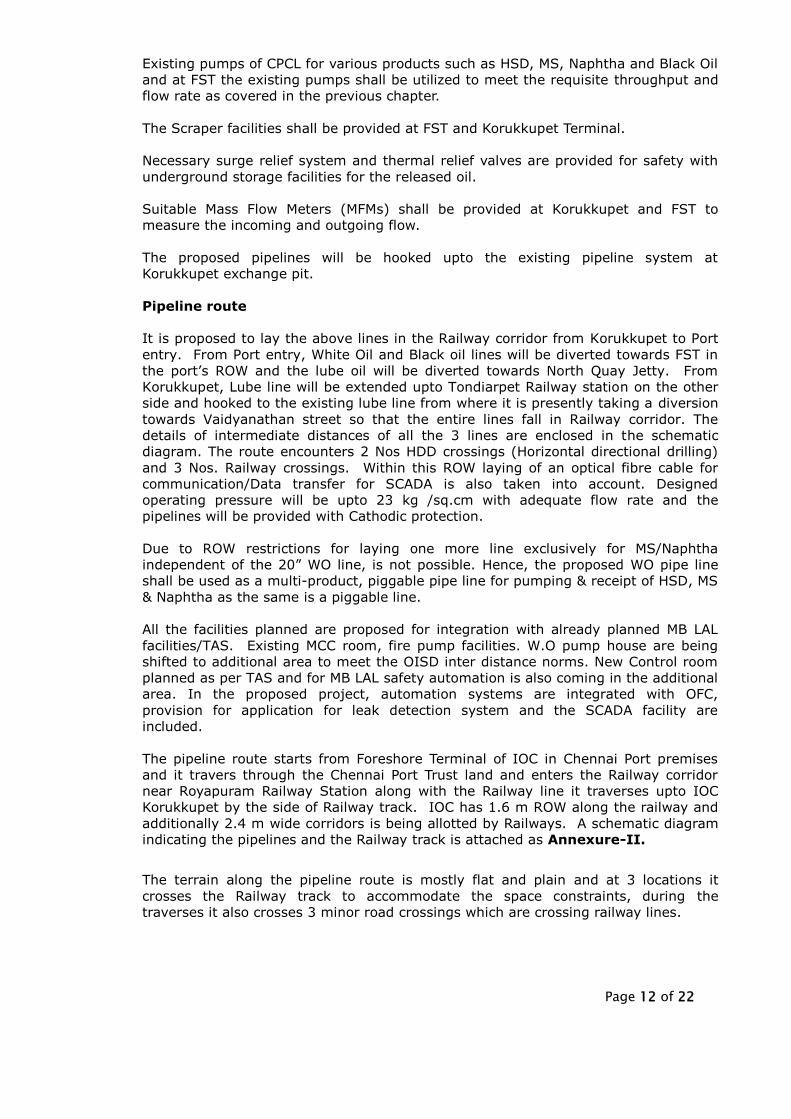
Existing pumps of CPCL for various products such as HSD, MS, Naphtha and Black Oil
and at FST the existing pumps shall be utilized to meet the requisite throughput and
flow rate as covered in the previous chapter.
The Scraper facilities shall be provided at FST and Korukkupet Terminal.
Necessary surge relief system and thermal relief valves are provided for safety with
underground storage facilities for the released oil.
Suitable Mass Flow Meters (MFMs) shall be provided at Korukkupet and FST to
measure the incoming and outgoing flow.
The proposed pipelines will be hooked upto the existing pipeline system at
Korukkupet exchange pit.
Pipeline route
It is proposed to lay the above lines in the Railway corridor from Korukkupet to Port
entry. From Port entry, White Oil and Black oil lines will be diverted towards FST in
the port’s ROW and the lube oil will be diverted towards North Quay Jetty. From
Korukkupet, Lube line will be extended upto Tondiarpet Railway station on the other
side and hooked to the existing lube line from where it is presently taking a diversion
towards Vaidyanathan street so that the entire lines fall in Railway corridor. The
details of intermediate distances of all the 3 lines are enclosed in the schematic
diagram. The route encounters 2 Nos HDD crossings (Horizontal directional drilling)
and 3 Nos. Railway crossings. Within this ROW laying of an optical fibre cable for
communication/Data transfer for SCADA is also taken into account. Designed
operating pressure will be upto 23 kg /sq.cm with adequate flow rate and the
pipelines will be provided with Cathodic protection.
Due to ROW restrictions for laying one more line exclusively for MS/Naphtha
independent of the 20” WO line, is not possible. Hence, the proposed WO pipe line
shall be used as a multi-product, piggable pipe line for pumping & receipt of HSD, MS
& Naphtha as the same is a piggable line.
All the facilities planned are proposed for integration with already planned MB LAL
facilities/TAS. Existing MCC room, fire pump facilities. W.O pump house are being
shifted to additional area to meet the OISD inter distance norms. New Control room
planned as per TAS and for MB LAL safety automation is also coming in the additional
area. In the proposed project, automation systems are integrated with OFC,
provision for application for leak detection system and the SCADA facility are
included.
The pipeline route starts from Foreshore Terminal of IOC in Chennai Port premises
and it travers through the Chennai Port Trust land and enters the Railway corridor
near Royapuram Railway Station along with the Railway line it traverses upto IOC
Korukkupet by the side of Railway track. IOC has 1.6 m ROW along the railway and
additionally 2.4 m wide corridors is being allotted by Railways. A schematic diagram
indicating the pipelines and the Railway track is attached as Annexure-II.
The terrain along the pipeline route is mostly flat and plain and at 3 locations it
crosses the Railway track to accommodate the space constraints, during the
traverses it also crosses 3 minor road crossings which are crossing railway lines.

Page 13 of 22
At railway crossing locations, cased crossing technique and 2 major crossings,
Horizontal Directional Drilling (HDD) technique is considered.
4.0 SITE ANALYSIS
Infrastructure
For installation and successful operation of the petroleum product pipelines, it is
imperative to ensure availability of the following infrastructure:
No structure of archaeological importance.
No agricultural land involved
No protected/reserve forest crossings are involved
No Rehabilitation and Resettlement (R&R) issues.
No stream or river crossings are involved
To be laid along the railway corridor and the port premises in the same corridor
were IOC had old lines which have been decommissioned and will be pulled out
to accommodate these proposed lines.
(i) Connectivity
The pipeline route is well connected by both railways and roadways. Within 5 km radius
Korukkupet, Royapuram and Washermanpet railway stations exists and the nearest bus
stand is at Korukkupet.
(ii) Land details
The pipeline route starts from Foreshore Terminal of IOC in Chennai Port premises and it
travers through the Chennai Port Trust land and enters the Railway corridor near
Royapuram Railway Station along with the Railway line it traverses upto IOC Korukkupet
by the side of Railway track. IOC has 1.6 m ROW along the railway and additionally 2.4
m wide corridor is being allotted by Railways.
(iii) Topography
The terrain along the pipeline route is mostly flat and plain and at 3 locations it
crosses the Railway track to accommodate the space constraints, during the
traverses it also crosses 3 minor road crossings which are crossing railway lines. At
railway crossing locations, cased crossing technique and 2 major crossings,
Horizontal Directional Drilling (HDD) technique is considered. The google image of
the pipeline route is shown in Figure-3.

Page 14 of 22
FIGURE-3
GOOGLE IMAGE OF THE PIPELINE ROUTE

Page 15 of 22
(iv) Existing land use pattern, shortest distances from the periphery of the
project to periphery of the forests, water bodies.
IOC has 1.6 m ROW along the railway and additionally 2.4 m wide corridor is being
allotted by Railways. There is no water bodies, forest and ecological sensitive area in the
pipeline route. Information on forests and water bodies nearer to the pipeline route is
given below:
Water Bodies:
There are two water bodies, namely Madavaram Eri and Bay of Bengal in the 10-km
radius from the boundary of Korukkupet IOC Terminal and Foreshore Terminal.
Forests:
No forest blocks within 10-km radius from the boundary of Korukkupet IOC Terminal
and Foreshore Terminal.
There are no sanctuaries, national parks, tiger or elephant reserves within 10 km
radius from the boundary of Korukkupet IOC Terminal and Foreshore Terminal.
(v) Climatic data from secondary source
The meteorological data from the secondary source collected from IMD Chennai is
given in the Table-4
TABLE-4
METEOROLOGICAL DATA
Annual Mean Ambient Temperature Max: 43.4°C
Min: 16.0°C
Relative Humidity Max: 100%
Min: 15%
Sea Water Temp 33°C
Total Rainfall 1215 mm
5.0 PLANNING BRIEF
(i) Planning concept (type of industries, facilities transportation etc).
Town and country planning/development authority classification
Relaying and rerouting of Petroleum Product Pipeline between IOCL,
Korukkupet and IOCL Fore Shore Terminal along the Railway corridor-Port
Premises. The Project location comes under Chennai Metropolitan Development
Authority (CMDA).
(ii) Population Projection: The distribution of population in 500 m on either side
of the pipeline route is shown in Table-5. As per 2011 census the study area
consisted of 428318 persons inhabited in study area.

Page 16 of 22
TABLE-5
DISTRIBUTION OF POPULATION ALONG THE PIPELINE LENGTH
Particulars 0-1
km
1-2
km
2-3
km
3-4
km
4-5
km
5-5.7
km
0-5.7
km
No. of Households 27302 22941 21157 16097 9639 5722 102858
Male Population 54268 46926 44996 34411 21159 12537 214297
Female Population 53927 47362 45335 33822 21442 12133 214021
Total Population 108195 94288 90331 68233 42601 24670 428318
Male Population (0-6
years) 6107 5588 4922 3576 2116 1232 23541
Female Population (0-
6 years) 5806 5437 4637 3353 1981 1167 22381
Total Population (0-6
years) 11913 11025 9559 6929 4097 2399 45922
% of 0-6 years
population 11.01 11.69 10.58 10.15 9.62 9.72 10.72
Average Household
Size 3.96 4.11 4.27 4.24 4.42 4.31 4.16
% of males to the
total population 50.16 49.77 49.81 50.43 49.67 50.82 50.03
% of females to the
total population 49.84 50.23 50.19 49.57 50.33 49.18 49.97
Sex Ratio (no of
females per 1000
males)
994 1009 1008 983 1013 968 999
Note: Starting point - Korukkupet terminal (0 km) and End point - Foreshore
Terminal (5.7 km)
The configuration of male and female indicates that the males constitute to about
50.03% and females to 49.97% of the total population as per 2011 census records.
The sex ratio i.e. the number of females per 1000 males indirectly reveals certain
sociological aspects in relation with female births, infant mortality among female
children and single person family structure, a resultant of migration of industrial
workers. The study area on an average has 999 females per 1000 males as per
2011 census reports.
Literacy Levels
The study area experiences a literacy rate of 85.12 % (2011).
6.0 PROPOSED INFRASTRUCTURE
Pump Station and Facilities
Civil
Civil structures are envisaged to be erected at the stations to provide shelter to
machineries. Pump shed and firefighting facilities for accommodating the pumping
units with associated facilities have been planned to be of steel structure. The civil
structures would also be provided to house control panels, MCC panels, HT/LT
panels, batteries, etc. All the safety factors like wind load, seismic load, soil bearing
capacity etc. would be taken into account while designing the civil structures.
Page 17 of 22
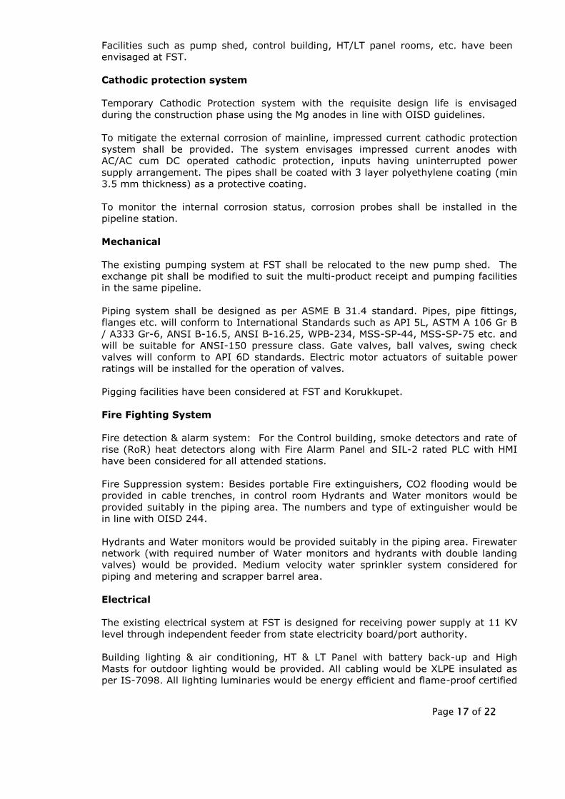
Facilities such as pump shed, control building, HT/LT panel rooms, etc. have been
envisaged at FST.
Cathodic protection system
Temporary Cathodic Protection system with the requisite design life is envisaged
during the construction phase using the Mg anodes in line with OISD guidelines.
To mitigate the external corrosion of mainline, impressed current cathodic protection
system shall be provided. The system envisages impressed current anodes with
AC/AC cum DC operated cathodic protection, inputs having uninterrupted power
supply arrangement. The pipes shall be coated with 3 layer polyethylene coating (min
3.5 mm thickness) as a protective coating.
To monitor the internal corrosion status, corrosion probes shall be installed in the
pipeline station.
Mechanical
The existing pumping system at FST shall be relocated to the new pump shed. The
exchange pit shall be modified to suit the multi-product receipt and pumping facilities
in the same pipeline.
Piping system shall be designed as per ASME B 31.4 standard. Pipes, pipe fittings,
flanges etc. will conform to International Standards such as API 5L, ASTM A 106 Gr B
/ A333 Gr-6, ANSI B-16.5, ANSI B-16.25, WPB-234, MSS-SP-44, MSS-SP-75 etc. and
will be suitable for ANSI-150 pressure class. Gate valves, ball valves, swing check
valves will conform to API 6D standards. Electric motor actuators of suitable power
ratings will be installed for the operation of valves.
Pigging facilities have been considered at FST and Korukkupet.
Fire Fighting System
Fire detection & alarm system: For the Control building, smoke detectors and rate of
rise (RoR) heat detectors along with Fire Alarm Panel and SIL-2 rated PLC with HMI
have been considered for all attended stations.
Fire Suppression system: Besides portable Fire extinguishers, CO2 flooding would be
provided in cable trenches, in control room Hydrants and Water monitors would be
provided suitably in the piping area. The numbers and type of extinguisher would be
in line with OISD 244.
Hydrants and Water monitors would be provided suitably in the piping area. Firewater
network (with required number of Water monitors and hydrants with double landing
valves) would be provided. Medium velocity water sprinkler system considered for
piping and metering and scrapper barrel area.
Electrical
The existing electrical system at FST is designed for receiving power supply at 11 KV
level through independent feeder from state electricity board/port authority.
Building lighting & air conditioning, HT & LT Panel with battery back-up and High
Masts for outdoor lighting would be provided. All cabling would be XLPE insulated as
per IS-7098. All lighting luminaries would be energy efficient and flame-proof certified

Page 18 of 22
for battery area. APFC Panel would also be provided to maintain power factor near
unity.
Instrumentation and Station Control Centre
FST and Korukkupet would be provided with hot standby PLC based station control
system to perform local control functioning and to monitor and control
The field instrumentation at FST & Korukkupet stations would comprise pressure
transmitters, pressure switches, pressure gauges, mass flow meters, temperature
gauge, temperature transmitter, scraper detector, emergency shutdown switches etc.
Station Control Centre (SCC) would have workstations as operator interface to the
station instrumentation and control system, on dual local area network (LAN) in client
server mode. 230 V UPS system with dual battery backup would be provided at
Korukkupet and FST.
Telecommunication system
Optical fibre cable shall be laid along with the main line which will be connected
through a Ethernet cum land switch at both the ends. The same shall be used for
data transfer between the 2 stations.
Supervisory Control and Data Acquisition (SCADA) System
Through Optical Fibre network the PLC system for automation shall be hooked up
through LAN network. A separate server shall be integrated with the automation
system. The requisite information for the purpose of control and monitoring of the
pipeline shall be acquired with suitable application software installed in the server.
Leak detection software also shall be installed in the server which will collect the data
from the system and work on a real time basis.
Implementation methodology
It is proposed to take up execution of the project through in-house expertise and
Pipelines Division of Indian Oil Corporation Ltd.
Statutory clearances
Petroleum and Explosion Safety Organisation (PESO) approval has been obtained for
re-routing/relaying project and other statutory clearances for the proposed pipeline
system from the concerned authorities, as applicable will be obtained.
7.0 REHABILITATION AND RESETTLEMENT (R & R) PLAN
There are no Rehabilitation and Resettlement R&R) plan involved.
IOC has approached Railways for increasing the existing ROW width from 1.6 m to 4
m and also extend ROW up to Port entry point from Old Royapuram Terminal with
uniform ROW width of 4M. Similarly, Port authority has been approached seeking ROW
from port entry point to FST and additional land for scrapper station adjacent to FST
and they have agreed in principle to give the ROW and additional land as can be seen
from their letter ref. MEE/V3/836/13/Dy.CME(OH) dt. 31.07.2014. Hence, the
additional land required at Chennai Port Trust and at Railway corridor has been taken
up with the appropriate authorities and is under advance stage of allotment.

Page 19 of 22
8.0 PROJECT SCHEDULE & COST ESTIMATES
(i) Likely date of Start of Construction and likely date of Completion
The proposed scheme is expected to be completed in a period of 6-10 months after
receipt of statutory clearances. The cost of project management & engineering is
estimated on the basis of this envisaged time schedule. The manpower requirement
during construction phase would be about 40 persons.
The pipeline system is estimated to cost 49.50 Crores including a foreign exchange
component of Rs. 27.6 lakhs at July 2014 price level. The proposal will be undertaken
as non-plan scheme for which necessary Budget provision will be included in RBE
2014-15 & BE 2015-16. The project will be undertaken through re-appropriation till
approval of the Budget.
The project cost for pipeline facilities has been estimated on the basis of the
following:
Cost actually incurred in the past with appropriate escalation.
Establishing physical requirements, preliminary specifications and in-house
cost data.
Experience of virtually identical projects elsewhere to establish physical
requirements and cost.
Experience of slightly different projects adjusted approximately to establish
physical requirements and budgetary quotations.
Experience of similar projects in value/terms adjusted for price difference by
past experience and escalation data.
Survey and field engineering
This cost includes the cost of surveys, sub-soil investigation & field engineering.
Additional Land and ROW
Additional Land required at FST and ROW in the Port areas are taken on lease basis.
The ROW on Railway land also will be taken on lease as per existing terms and
conditions.
Mainline Pipes & Materials
The cost of pipe and coating has been considered as per the latest data available.
The cost of mainline materials required such as casing pipe, coating and wrapping
materials, valves etc. has been estimated on the basis of budgetary offers and cost
actually incurred in recent past on similar items.
Mainline Construction
The cost of mainline construction has been estimated on the basis of the cost
incurred in similar project executed elsewhere, suitably adjusted to bring it to July
2014 price level.
Pump Station and Terminal
Since approvals for both TAS (Terminal automation system) and MB LAL works have
been obtained and facilities are yet to come up, these facilities will be integrated to
meet the dock line operational, control and monitoring objectives. This is necessary

Page 20 of 22
as they have to function in a co-ordinated manner as the objectives are same and
accordingly while drawing the estimates for the project this aspect has been
considered.
Cathodic Protection
This includes the cost of materials required for temporary and permanent cathodic
protection, installation & commissioning of equipment/materials, CP rectifier units,
ground beds, cable etc. Estimates are based on budgetary offers and the rates from
similar projects executed in the recent past.
Telecommunication and Tele supervisory System
Cost estimates are based on budgetary offers/earlier purchase orders, adjusted
suitably.
9. ANALYSIS OF PROPOSAL (FINAL RECOMMENDATIONS)
Financial and Social Benefits
The project related pipeline installation activities will benefit the local populace in a
number of ways such as supply of construction labourers – skilled, semi-skilled and
un-skilled, tertiary sector employment and provision of goods and services for daily
needs including transport. This project will facilitate better safety, management and
maintenance of dock lines. Hence, the project will have positive impact in the region.

Page 21 of 22
ANNEXURE-I
LAYOUT OF THE PIPELINE ROUTE (EXISTING & PROPOSED PIPELINE)

Page 22 of 22
ANNEXURE-II
SCHEMATIC DIAGRAM INDICATING THE PIPELINES AND THE RAILWAY TRACK