PRE FEASIBILITY REPORT -...
23
PRE FEASIBILITY REPORT For Proposed Expansion in Dyes Intermediate Manufacturing Plant M/S. CRYSTAL QUINONE PVT. LTD. Plot No. 143 & 145, Phase – II, GIDC-Vatva, Ahmedabad-382445 1
Transcript of PRE FEASIBILITY REPORT -...

PRE FEASIBILITY REPORT
For
Proposed Expansion in Dyes Intermediate Manufacturing Plant
M/S. CRYSTAL QUINONE PVT. LTD. Plot No. 143 & 145, Phase – II,
GIDC-Vatva, Ahmedabad-382445
1

CONTENTS
Sr. No Description Page No. 1. Executive Summary 3 2. Introduction of the Project/Background information 12 3. Project Description 13 4. Site Analysis 17 5. Planning Brief 18 6. Proposed Infrastructure 19 7. Rehabilitation and resettlement (R & R) Plan 23 8. Project Schedule & Cost Estimates 23 9. Analysis of Proposal (Final Recommendations) 23
2
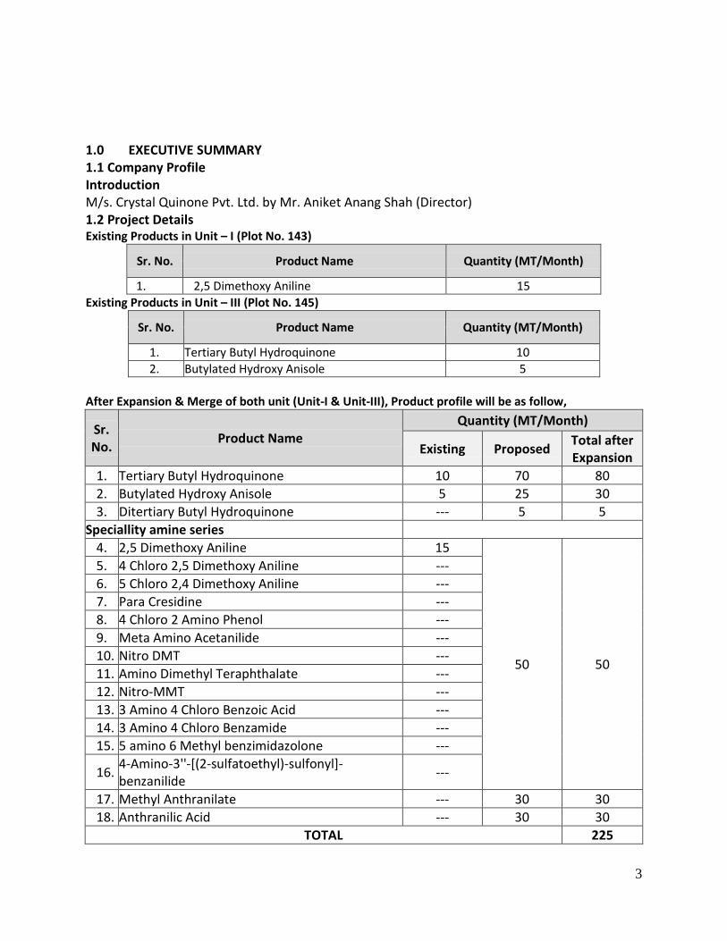
1.0 EXECUTIVE SUMMARY 1.1 Company Profile Introduction M/s. Crystal Quinone Pvt. Ltd. by Mr. Aniket Anang Shah (Director) 1.2 Project Details Existing Products in Unit – I (Plot No. 143)
Sr. No. Product Name Quantity (MT/Month)
1. 2,5 Dimethoxy Aniline 15 Existing Products in Unit – III (Plot No. 145)
Sr. No. Product Name Quantity (MT/Month)
1. Tertiary Butyl Hydroquinone 10 2. Butylated Hydroxy Anisole 5
After Expansion & Merge of both unit (Unit-I & Unit-III), Product profile will be as follow,
Sr. No. Product Name
Quantity (MT/Month)
Existing Proposed Total after Expansion
1. Tertiary Butyl Hydroquinone 10 70 80 2. Butylated Hydroxy Anisole 5 25 30 3. Ditertiary Butyl Hydroquinone --- 5 5
Speciallity amine series 4. 2,5 Dimethoxy Aniline 15
50 50
5. 4 Chloro 2,5 Dimethoxy Aniline --- 6. 5 Chloro 2,4 Dimethoxy Aniline --- 7. Para Cresidine --- 8. 4 Chloro 2 Amino Phenol --- 9. Meta Amino Acetanilide --- 10. Nitro DMT --- 11. Amino Dimethyl Teraphthalate --- 12. Nitro-MMT --- 13. 3 Amino 4 Chloro Benzoic Acid --- 14. 3 Amino 4 Chloro Benzamide --- 15. 5 amino 6 Methyl benzimidazolone ---
16. 4-Amino-3''-[(2-sulfatoethyl)-sulfonyl]-benzanilide ---
17. Methyl Anthranilate --- 30 30 18. Anthranilic Acid --- 30 30
TOTAL 225
3

1.3 Green Belt Development Company shall develop an effective green belt within the factory and on periphery of the factory. In addition to this, majority of the vacant land shall be planted with trees, shrubs and grasses. 1.4 Power & Fuel Requirement Energy: Source of power is Torrent Power Fuel Requirement:
Existing in Unit – I (Plot No. 143) Sr. No. Fuel Used in Quantity
Existing Proposed Total
1. Natural Gas Baby Boiler (Existing) 25 SCM/Hr. ---- 25 SCM/Hr.
2. Natural Gas Thermic Fluid Heater (Proposed) 50 SCM/Hr. ---- 50 SCM/Hr.
Existing in Unit – III (Plot No. 145)
Sr. No. Fuel Used in Quantity
Existing Proposed Total
1. Natural Gas Steam Boiler (Existing) 200 m3/Day ---- 200 m3/Day
2. LDO Non IBR Boiler (Existing) 500 L/Day ---- 500 L/Day
*After Expansion & merge of both units (Plot 143 & 145)
Sr. No. Fuel Used in Quantity
Existing Proposed Total
1. Natural Gas Baby Boiler (Existing) 25 SCM/Hr. ---- 25 SCM/Hr.
2. Natural Gas Thermic Fluid Heater (Proposed) 50 SCM/Hr. ---- 50 SCM/Hr.
3. Natural Gas Steam Boiler (Existing) 200 m3/Day ---- 200 m3/Day
4. LDO Non IBR Boiler (Existing) 500 L/Day ---- 500 L/Day
(Note*; after expansion our both units Plot no. 143 & 145 will be merged in single unit)
4
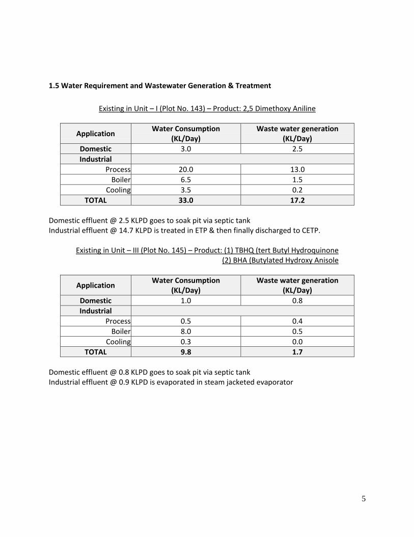
1.5 Water Requirement and Wastewater Generation & Treatment
Existing in Unit – I (Plot No. 143) – Product: 2,5 Dimethoxy Aniline
Application Water Consumption (KL/Day)
Waste water generation (KL/Day)
Domestic 3.0 2.5 Industrial
Process 20.0 13.0 Boiler 6.5 1.5
Cooling 3.5 0.2 TOTAL 33.0 17.2
Domestic effluent @ 2.5 KLPD goes to soak pit via septic tank Industrial effluent @ 14.7 KLPD is treated in ETP & then finally discharged to CETP.
Existing in Unit – III (Plot No. 145) – Product: (1) TBHQ (tert Butyl Hydroquinone (2) BHA (Butylated Hydroxy Anisole
Application Water Consumption (KL/Day)
Waste water generation (KL/Day)
Domestic 1.0 0.8 Industrial
Process 0.5 0.4 Boiler 8.0 0.5
Cooling 0.3 0.0 TOTAL 9.8 1.7
Domestic effluent @ 0.8 KLPD goes to soak pit via septic tank Industrial effluent @ 0.9 KLPD is evaporated in steam jacketed evaporator
5

*After expansion & merge of both units, water profile will be as follow,
Application
Water Consumption (KL/Day)
Waste water generation (KL/Day)
Existing Proposed Total After Expansion Existing Proposed Total After
Expansion
Domestic 4.0 2.0 6.0 3.3 1.5 4.8 Industrial
Process 20.5 86.7 107.2 13.4 96.7 110.1 Boiler 14.5 2.9 17.4 2.0 0.4 2.4
Cooling 3.8 3.7 7.5 0.2 0.2 0.4 Scrubber --- 1.5 1.5 --- --- ---
TOTAL 42.8 96.8 139.6 18.9 98.8 117.7 Existing
→ Total Water consumption is 42.8 KLPD. → Domestic water consumption is 4.0 KLPD & waste water 3.3 KLPD goes to soak pit via
septic tank. → Total Industrial waste water generation is 15.6 KLPD. From which 0.9 KLPD is evaporated
in steam jacketed evaporator & 14.7 KLPD treated in ETP then finally discharged to CETP for further treatment.
Proposed (After Expansion) → Total Water consumption will be 139.6 KLPD (Domestic: 6.0 KLPD + Industrial: 133.6
KLPD). → Domestic waste water @ 4.8 KLPD will be discharged to soak pit via septic tank. → Industrial waste water generation will be 112.9 KLPD. It will be managed by as follow,
• Process w/w (13.0 KLPD) + Boiler Blow down w/w (1.5 KLPD) + Cooling Blow down w/w (0.2 KLPD) = 14.7 KLPD will be discharged to CETP.
• Process w/w (0.4 KLPD) + Boiler blow down (0.5 KLPD) = 0.9 KLPD is goes to Steam Jacketed evaporator for evaporation.
• Process w/w 96.7 from which Recycled w/w 65.2 KLPD will be reuse in process & High COD(31.5 KLPD) + Cooling Blow Down (0.2 KLPD) + Boiler blow down (0.4 KLPD) = 32.1 KLPD will be discharged to MEE (Multi effect evaporator) for evaporation.
(Note*; after expansion our both units Plot no. 143 & 145 will be merged in single unit)
6

1.6 Air Pollution Source and Control Management → The source of air pollution due to the project will be Flue gas emission. The source of flue
gas emission will be from the stack attached to Boiler & Thermic fluid heater. Dust collector should be provided as APCM to prevent flue gas emission. Source of Process gas emission will be from the stack attached to Spray dryer & as a part of prevention, we will provide water scrubber.
(A) Details of Flue Gas Stack ;
Existing in Unit – I (Plot No. 143)
Sr. No. Stack Attached To Stack height
(meter) APCM System Parameter Permissible limit
1 Baby Boiler (300 Kg/Hr.) 11 ---- SPM
SO2 NOx
150 mg/ NM3 100 ppm 50 ppm 2 Thermic Fluid Heater
(200U) 10 ----
Existing in Unit – III (Plot No. 145)
Sr. No. Stack Attached To Stack height
(meter) APCM System Parameter Permissible limit
1 Steam Boiler (2 TPH) 11 ---- SPM SO2 NOx
150 mg/ NM3 100 ppm 50 ppm 2 Non IBR Boiler 11 ----
*After Expansion & merge of both units (Plot 143 & 145)
Sr. No. Stack Attached To Stack height
(meter) APCM System Parameter Permissible limit
1 Baby Boiler (300 Kg/Hr.) 11 ----
SPM SO2 NOx
150 mg/ NM3 100 ppm 50 ppm
2 Thermic Fluid Heater (200U) 10 ----
3 Steam Boiler (2 TPH) 11 Dust Collector
4 Non IBR Boiler 11 ----
7
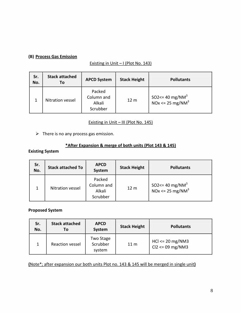
(B) Process Gas Emission
Existing in Unit – I (Plot No. 143)
Sr. No.
Stack attached To APCD System Stack Height Pollutants
1 Nitration vessel
Packed Column and
Alkali Scrubber
12 m SO2<= 40 mg/NM3 NOx <= 25 mg/NM3
Existing in Unit – III (Plot No. 145)
There is no any process gas emission.
*After Expansion & merge of both units (Plot 143 & 145)
Existing System
Sr. No. Stack attached To APCD
System Stack Height Pollutants
1 Nitration vessel
Packed Column and
Alkali Scrubber
12 m SO2<= 40 mg/NM3 NOx <= 25 mg/NM3
Proposed System
Sr. No.
Stack attached To
APCD System Stack Height Pollutants
1 Reaction vessel Two Stage Scrubber system
11 m HCl <= 20 mg/NM3 Cl2 <= 09 mg/NM3
(Note*; after expansion our both units Plot no. 143 & 145 will be merged in single unit)
8

1.7 Hazardous Waste generation & Management
Existing in Unit – I (Plot No. 143)
Sr. No.
Type of Hazardous Waste
Cat. No.
Quantity (MT/Year) Management
1. ETP Sludge 35.3 9.0 Collection, Storage, Transportation, Disposal to TSDF site by GEMSPL-Vatva
2. Spent Acid D2 of Sch. II 25.0
Collection, Storage, Transportation & used for neutralization of effluent in ETP
3. Used Oil 5.1 0.025 Collection, Storage, Transportation and Reuse by self /ultimately sell to registered re refiners
4. Discarded Containers 33.1 2.0 Collection, Storage, Transportation and Reuse by self /given back to supplier/sold to Registered recyclers
Existing in Unit – III (Plot No. 145)
Sr. No.
Type of Hazardous Waste
Cat. No.
Quantity (MT/Year) Management
1. Process Waste 26.1 5.0 Collection, Storage, Transportation, Disposal to TSDF site
2. Evaporation Ash 36.2 5.0 Collection, Storage, Transportation, Disposal to TSDF site
3. Used Oil 5.1 0.040 Collection, Storage, Transportation and Reuse for lubrication/ sell to registered recyclers in case of need arise
4. Discarded Containers/Bags 33.1 2.0
Collection, Storage, Transportation and Reuse by self /given back to supplier/sold to Registered recyclers
9

*After Expansion & merge of both units (Plot 143 & 145)
Sr. No
Type of Hazardous Waste Cat. No.
Quantity (MT/Year)
Existing Proposed Total after expansion
1. ETP Sludge 35.3 9.0 11.0 20.0
2. Spent Acid D2 of Sch. II 25.0 -25.0 -----
3. Process Waste 26.1 5.0 31.0 36.0 4. Evaporation Ash 36.2 5.0 25.0 30.0
5. 1,4-Dimethoxy Benzene ---- ----- 86.0 86.0
6. Dilute Hydrochloric Acid
Sr. No. 15 Class-C ----- 670 670
7. Sodium Bi Sulfite ---- ----- 2900 2900 8. Distillation Residue 36.4 ----- 96.0 96.0 9. Used Oil 5.1 0.065 0.435 0.500
10. Discarded Containers/Bags/ Liners
33.1 4.0 76.0 80.0
Management of Hazardous waste
Sr. No.
Type of waste and category
Source of generation Collection Storage Disposal
1. ETP Sludge Effluent treatment plant
H.D.P.E Bags
Solid waste storage area with proper bag packing
Collection, Storage, Transportation, Disposal to TSDF site by GEMSPL-Vatva
2. Spent Acid From manufacturing process
Storage Tank MS Storage tank
Collection, Storage, Transportation & used for neutralization of effluent in ETP
3. Process Waste
From manufacturing process & ancillary operation
HDPE Bags/liners
Solid waste storage area with proper bag packing
Collection, Storage, Transportation, Disposal to TSDF site
10
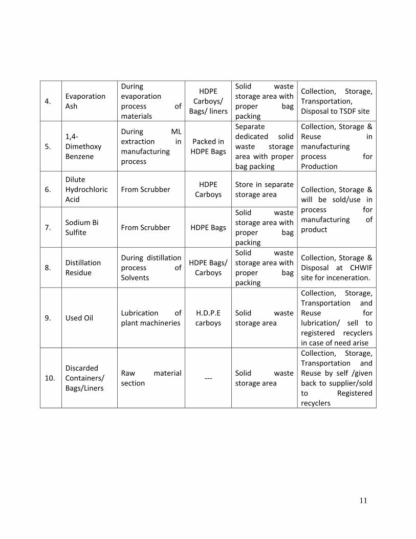
4. Evaporation Ash
During evaporation process of materials
HDPE Carboys/
Bags/ liners
Solid waste storage area with proper bag packing
Collection, Storage, Transportation, Disposal to TSDF site
5. 1,4-Dimethoxy Benzene
During ML extraction in manufacturing process
Packed in HDPE Bags
Separate dedicated solid waste storage area with proper bag packing
Collection, Storage & Reuse in manufacturing process for Production
6. Dilute Hydrochloric Acid
From Scrubber HDPE Carboys
Store in separate storage area Collection, Storage &
will be sold/use in process for manufacturing of product 7. Sodium Bi
Sulfite From Scrubber HDPE Bags
Solid waste storage area with proper bag packing
8. Distillation Residue
During distillation process of Solvents
HDPE Bags/ Carboys
Solid waste storage area with proper bag packing
Collection, Storage & Disposal at CHWIF site for inceneration.
9. Used Oil Lubrication of plant machineries
H.D.P.E carboys
Solid waste storage area
Collection, Storage, Transportation and Reuse for lubrication/ sell to registered recyclers in case of need arise
10. Discarded Containers/ Bags/Liners
Raw material section --- Solid waste
storage area
Collection, Storage, Transportation and Reuse by self /given back to supplier/sold to Registered recyclers
11
2.0 INTRODUCTION OF THE PROJECT/BACKGROUND INFORMATION 2.1 Identification of the project and project proponent. In case of mining project, a copy of mining lease/letter of intent should be given. Identification of the project Proposed expansion in existing Dyes intermediate manufacturing plant (Plot 143 & 145) Identification of the project proponent Presently following is the Directors of the company:-
1 Mr. Aniet Anang Shah (Director)
2.2 Brief description of nature of the Project Proposed expansion in existing Dyes intermediate manufacturing plant (Plot 143 & 145). 2.3 Need for the project and its importance to the country and or region The objective is to be achieved by: • Continuously reducing the Costs & improving Quality. • To generate local employment 2.4 Demands-Supply Gap
Based on our informal survey of the market with our current customers and various traders, we have found that there is a big potential for the range of the products we are planning.
2.5 Imports vs. Indigenous production Based on the current cost of indigenous raw materials and the non availability of some materials, No import will be done for any of our Raw Material. This will make us very competitive against imported finished products and we will be able to increase the export of our finished products. 2.6 Export possibility We shall explore the possibility of export the products.
2.7 Domestic/Export Markets We shall explore the possibility of domestic/export the products.
2.8 Employment Generation (Direct and Indirect) due to project. Employment would be as per prevailing norms of state government for skilled and unskilled people for the proposed expansion project.

3.0 Project Description
3.1 Type of Project including interlinked and interdependent projects, if any. - Category: 5(f) 3.2 Location (map showing general location, specific location and project boundary & project
site layout) with coordinates. Map showing general location Layout Plan: Enclosed in EC Application: Please Refer Enclosure: 15 3.3 Details of alternate sites considered and the basis of selecting the proposed site, particularly the environmental considerations gone into should be highlighted. Major factors involved in the selection of site are listed below: • Site is very well connected by road • Availability of sufficient land free from cultivation • Availability of power evacuation facilities • Availability of water for industrial use Modern infrastructure support and amenities at par with industrial estates in other global markets, including: Efficient transport facilities within the industrial estate and to & from the city area. Environment-friendly zone. Uninterrupted power supply
3.4 Size or Magnitude of Operation
Sr. No. Product Name
Quantity (MT/Month)
Existing Proposed Total after Expansion
1. Tertiary Butyl Hydroquinone 10 70 80 2. Butylated Hydroxy Anisole 5 25 30 3. Ditertiary Butyl Hydroquinone --- 5 5
Speciallity amine series 4. 2,5 Dimethoxy Aniline 15
50 50
5. 4 Chloro 2,5 Dimethoxy Aniline --- 6. 5 Chloro 2,4 Dimethoxy Aniline --- 7. Para Cresidine --- 8. 4 Chloro 2 Amino Phenol --- 9. Meta Amino Acetanilide --- 10. Nitro DMT --- 11. Amino Dimethyl Teraphthalate --- 12. Nitro-MMT ---

13. 3 Amino 4 Chloro Benzoic Acid --- 14. 3 Amino 4 Chloro Benzamide --- 15. 5 amino 6 Methyl benzimidazolone ---
16. 4-Amino-3''-[(2-sulfatoethyl)-sulfonyl]-benzanilide ---
17. Methyl Anthranilate --- 30 30 18. Anthranilic Acid --- 30 30
TOTAL 225 3.5 Project Description with process details (a schematic diagram/flow chart showing the project layout, components of the project etc. should be given) Please refer Enclosure 8 in EC Application. 3.6 Raw material required along with estimated quantity, likely source, marketing area of final products. Mode of transport of raw materials and finished products. Please refer Enclosure 3 in EC Application. 3.7 Resource optimization/recycling and reuse envisaged in the project, if any, should be briefly outlined. We will explore possibility of optimization/recycling and reuse envisaged in the project. 3.8 Availability of water its source, energy/power requirement and source should be given. Power & Fuel Requirement Energy Power supply is available from Torrent Power. Fuel
Existing in Unit – I (Plot No. 143)
Sr. No. Fuel Used in Quantity
Existing Proposed Total
1. Natural Gas Baby Boiler (Existing) 25 SCM/Hr. ---- 25 SCM/Hr.
2. Natural Gas Thermic Fluid Heater (Proposed) 50 SCM/Hr. ---- 50 SCM/Hr.
Existing in Unit – III (Plot No. 145) Sr. No. Fuel Used in Quantity
Existing Proposed Total
1. Natural Gas Steam Boiler (Existing) 200 m3/Day ---- 200 m3/Day
2. LDO Non IBR Boiler (Existing) 500 L/Day ---- 500 L/Day
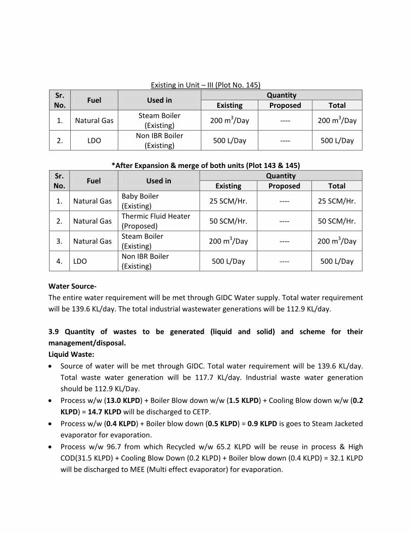
*After Expansion & merge of both units (Plot 143 & 145)
Sr. No. Fuel Used in Quantity
Existing Proposed Total
1. Natural Gas Baby Boiler (Existing) 25 SCM/Hr. ---- 25 SCM/Hr.
2. Natural Gas Thermic Fluid Heater (Proposed) 50 SCM/Hr. ---- 50 SCM/Hr.
3. Natural Gas Steam Boiler (Existing) 200 m3/Day ---- 200 m3/Day
4. LDO Non IBR Boiler (Existing) 500 L/Day ---- 500 L/Day
Water Source- The entire water requirement will be met through GIDC Water supply. Total water requirement will be 139.6 KL/day. The total industrial wastewater generations will be 112.9 KL/day. 3.9 Quantity of wastes to be generated (liquid and solid) and scheme for their management/disposal. Liquid Waste: • Source of water will be met through GIDC. Total water requirement will be 139.6 KL/day.
Total waste water generation will be 117.7 KL/day. Industrial waste water generation should be 112.9 KL/Day.
• Process w/w (13.0 KLPD) + Boiler Blow down w/w (1.5 KLPD) + Cooling Blow down w/w (0.2 KLPD) = 14.7 KLPD will be discharged to CETP.
• Process w/w (0.4 KLPD) + Boiler blow down (0.5 KLPD) = 0.9 KLPD is goes to Steam Jacketed evaporator for evaporation.
• Process w/w 96.7 from which Recycled w/w 65.2 KLPD will be reuse in process & High COD(31.5 KLPD) + Cooling Blow Down (0.2 KLPD) + Boiler blow down (0.4 KLPD) = 32.1 KLPD will be discharged to MEE (Multi effect evaporator) for evaporation.
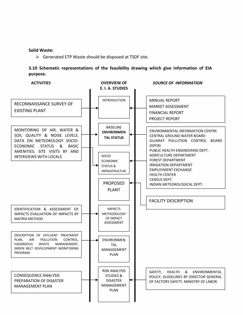
Solid Waste: Generated ETP Waste should be disposed at TSDF site.
3.10 Schematic representations of the feasibility drawing which give information of EIA purpose.
RECONNAISSANCE SURVEY OF EXISTING PLANT
ANNUAL REPORT MARKET ASSESSMENT FINANCIAL REPORT PROJECT REPORT
INTRODUCTION
MONITORING OF AIR, WATER & SOIL QUALITY & NOISE LEVELS. DATA ON METEOROLOGY SOCIO-ECONOMIC STATUS & BASIC AMENITIES. SITE VISITS BY AND INTERVIEWS WITH LOCALS
BASELINE ENVIRONMEN
TAL STATUS
ENVIRONMENTAL INFORMATION CENTRE CENTRAL GROUND WATER BOARD GUJARAT POLLUTION CONTROL BOARD (GPCB) PUBLIC HEALTH ENGINEERING DEPT. AGRICULTURE DEPARTMENT FOREST DEPARTMENT IRRIGATION DEPARTMENT EMPLOYMENT EXCHANGE HEALTH CENTER CENSUS DEPT. INDIAN METEOROLOGICAL DEPT.
SOCIO ECONOMIC STATUS & INFRASTRUCTUR
PROPOSED PLANT
FACILITY DESCRIPTION
IMPACTS METHODOLOGY
OF IMPACT ASSESSMENT
IDENTIFICATION & ASSESSMENT OF IMPACTS EVALUATION OF IMPACTS BY MATRIX METHOD
SOURCE OF INFORMATION OVERVIEW OF E. I. A. STUDIES
ACTIVITIES
ENVIRONMENTAL
MANAGEMENT PLAN
DESCRIPTION OF EFFLUENT TREATMENT PLAN, AIR POLLUTION CONTROL, HAZARDOUS WASTE MANAGEMENT, GREEN BELT DEVELOPMENT MONITORING PROGRAM
RISK ANALYSIS STUDIES & DISASTER
MANAGEMENT PLAN
SAFETY, HEALTH & ENVIRONMENTAL POLICY, GUIDELINES BY DIRECTOR GENERAL OF FACTORY SAFETY, MINISTRY OF LABOR.
CONSEQUENCE ANALYSIS PREPARATION OF DISASTER MANAGEMENT PLAN
4.0 Site Analysis 4.1 Connectivity
1. Site is very well connected by road 2. Availability of power evacuation facilities 3. Availability of water for industrial use
4.2 Land Form, Land Use and Land Ownership It will be incorporated in EIA Studies. 4.3 Topography (along with map) We will be incorporated topography in EIA Studies. 4.4 Existing land use pattern (agriculture, non-agriculture, forest, water bodies (including area under CRZ)), shortest distances from the periphery of the project to periphery of the forests, national park, wild life sanctuary, eco sensitive areas, water bodies (distance from HFL of the river), CRZ. In case of the notified industrial area, a copy of the Gazette notification should be given. It will be incorporated in EIA Studies. CRZ Clearance is not applicable to us. 4.5 Existing Infrastructure Existing Infrastructures facilities are listed below: Site is very well connected by road Proximity to Raw Material suppliers Availability of sufficient land free form cultivation. Availability of power evacuation facilities 4.6 Soil Classification It will be incorporated in EIA Studies. 4.7 Climatic data from secondary sources. Secondary Sources our own weather station. 4.8 Social infrastructure available. Depending on the growth of the company the required social infrastructure will be provided.

5.0 Planning Brief 5.1 Planning Concept (type of industries, facilities, transportation etc) Town and Country planning/Development authority classification. Type of Industry: Synthetic Organic Chemical Industries Facility: Administration, Transportation 5.2 Population Projection We will include in EIA Report. 5.3 Land use planning (breakup along with green belt etc.) Plot Area: Plot No. 143 – 1622 Sq.m., Plot No. 145 – 704 Sq.m. 5.4 Assessment of Infrastructure Demand (Physical & Social) • Employment would be as per prevailing norms of state government for skilled and unskilled
people for the proposed expansion project. • Social Welfare • Cordial relation with the industry shall be established and representation shall be made to
villagers for help for creation of facilities related to health, education, etc. 5.5 Amenities/Facilities It will be incorporated in the EIA Studies.

6.0 Proposed Infrastructure 6.1 Industrial Area (Processing Area) Processing Area (Processing Zone, and Utility Area) – Please Refer Plant Layout 6.2 Residential Area (Non Processing Area) Non Processing Area (Green belt, Raw material storage area, Finished storage area, Open space) - Please Refer Plant Layout in Enclosure 15. 6.3 Green Belt Company shall develop an effective green belt within the factory and on periphery of the factory. In addition to this, majority of the vacant land shall be planted with trees, shrubs and grasses. 6.4 Social Infrastructure Depending on the growth of the company the required social infrastructure will be provided. 6.5 Connectivity (Traffic and Transportation Road/ Rail/Metro/ Water ways etc) Site is very well connected by road & railway 6.6 Drinking water Management (Source & Supply of water) Water requirement will meet through the GIDC 6.7 Sewerage System Sewage pipes would be laid in entire company for the removal and disposal of mainly non-harmful liquid wastes from the offices, canteen and domestic waste coming from different sections. These liquid wastes would be treated (If required) and disposed by septic tank and soak pit.
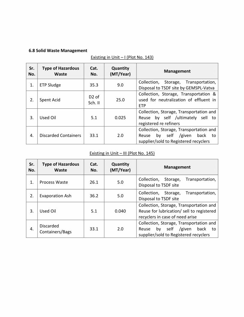
6.8 Solid Waste Management Existing in Unit – I (Plot No. 143)
Sr. No.
Type of Hazardous Waste
Cat. No.
Quantity (MT/Year) Management
1. ETP Sludge 35.3 9.0 Collection, Storage, Transportation, Disposal to TSDF site by GEMSPL-Vatva
2. Spent Acid D2 of Sch. II 25.0
Collection, Storage, Transportation & used for neutralization of effluent in ETP
3. Used Oil 5.1 0.025 Collection, Storage, Transportation and Reuse by self /ultimately sell to registered re refiners
4. Discarded Containers 33.1 2.0 Collection, Storage, Transportation and Reuse by self /given back to supplier/sold to Registered recyclers
Existing in Unit – III (Plot No. 145)
Sr. No.
Type of Hazardous Waste
Cat. No.
Quantity (MT/Year) Management
1. Process Waste 26.1 5.0 Collection, Storage, Transportation, Disposal to TSDF site
2. Evaporation Ash 36.2 5.0 Collection, Storage, Transportation, Disposal to TSDF site
3. Used Oil 5.1 0.040 Collection, Storage, Transportation and Reuse for lubrication/ sell to registered recyclers in case of need arise
4. Discarded Containers/Bags 33.1 2.0
Collection, Storage, Transportation and Reuse by self /given back to supplier/sold to Registered recyclers
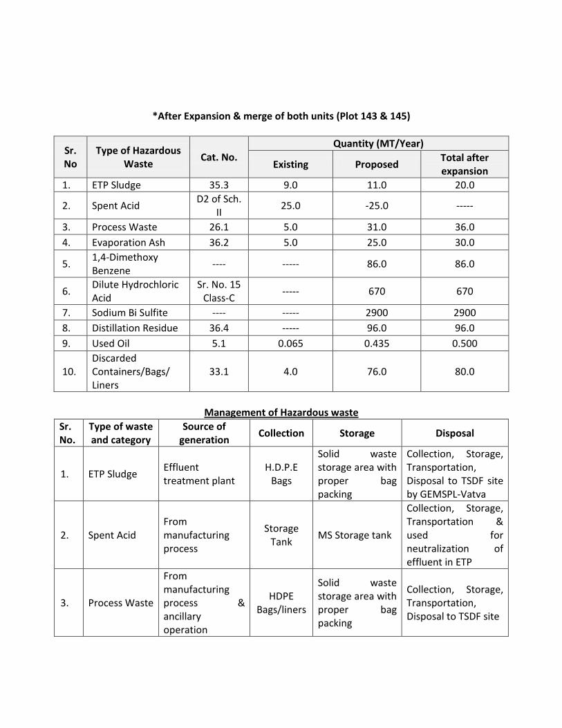
*After Expansion & merge of both units (Plot 143 & 145)
Sr. No
Type of Hazardous Waste Cat. No.
Quantity (MT/Year)
Existing Proposed Total after expansion
1. ETP Sludge 35.3 9.0 11.0 20.0
2. Spent Acid D2 of Sch. II 25.0 -25.0 -----
3. Process Waste 26.1 5.0 31.0 36.0 4. Evaporation Ash 36.2 5.0 25.0 30.0
5. 1,4-Dimethoxy Benzene ---- ----- 86.0 86.0
6. Dilute Hydrochloric Acid
Sr. No. 15 Class-C ----- 670 670
7. Sodium Bi Sulfite ---- ----- 2900 2900 8. Distillation Residue 36.4 ----- 96.0 96.0 9. Used Oil 5.1 0.065 0.435 0.500
10. Discarded Containers/Bags/ Liners
33.1 4.0 76.0 80.0
Management of Hazardous waste
Sr. No.
Type of waste and category
Source of generation Collection Storage Disposal
1. ETP Sludge Effluent treatment plant
H.D.P.E Bags
Solid waste storage area with proper bag packing
Collection, Storage, Transportation, Disposal to TSDF site by GEMSPL-Vatva
2. Spent Acid From manufacturing process
Storage Tank MS Storage tank
Collection, Storage, Transportation & used for neutralization of effluent in ETP
3. Process Waste
From manufacturing process & ancillary operation
HDPE Bags/liners
Solid waste storage area with proper bag packing
Collection, Storage, Transportation, Disposal to TSDF site
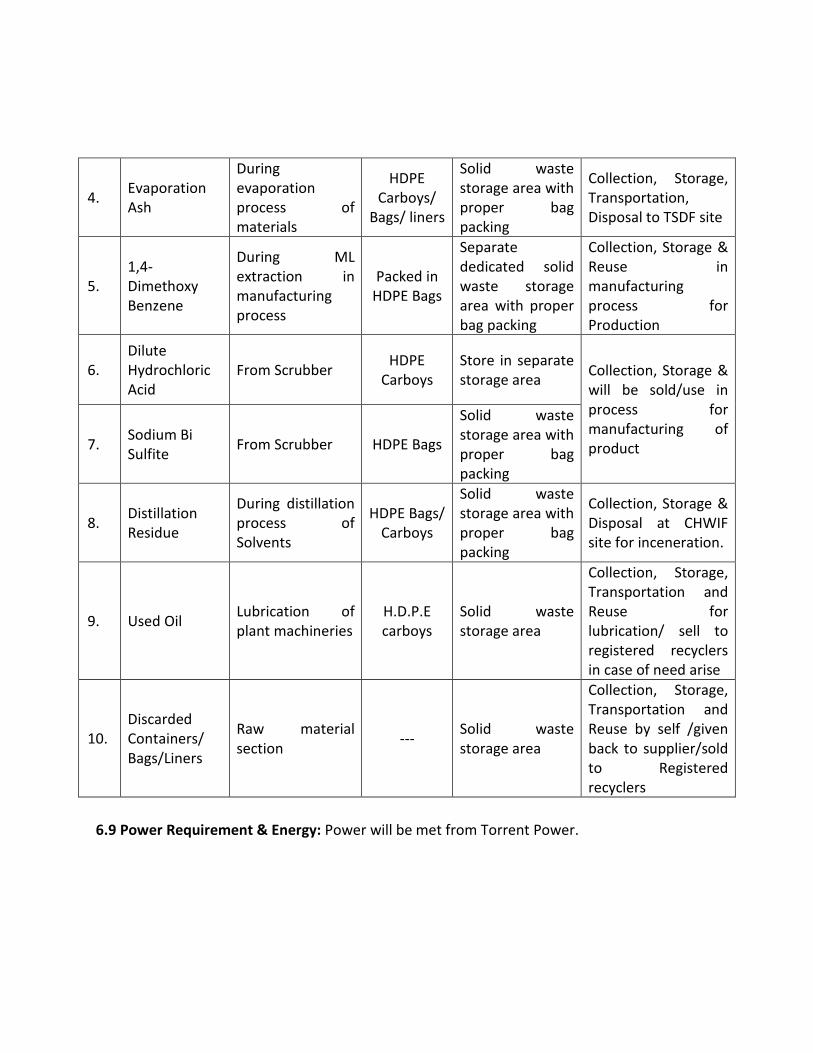
4. Evaporation Ash
During evaporation process of materials
HDPE Carboys/
Bags/ liners
Solid waste storage area with proper bag packing
Collection, Storage, Transportation, Disposal to TSDF site
5. 1,4-Dimethoxy Benzene
During ML extraction in manufacturing process
Packed in HDPE Bags
Separate dedicated solid waste storage area with proper bag packing
Collection, Storage & Reuse in manufacturing process for Production
6. Dilute Hydrochloric Acid
From Scrubber HDPE Carboys
Store in separate storage area Collection, Storage &
will be sold/use in process for manufacturing of product 7. Sodium Bi
Sulfite From Scrubber HDPE Bags
Solid waste storage area with proper bag packing
8. Distillation Residue
During distillation process of Solvents
HDPE Bags/ Carboys
Solid waste storage area with proper bag packing
Collection, Storage & Disposal at CHWIF site for inceneration.
9. Used Oil Lubrication of plant machineries
H.D.P.E carboys
Solid waste storage area
Collection, Storage, Transportation and Reuse for lubrication/ sell to registered recyclers in case of need arise
10. Discarded Containers/ Bags/Liners
Raw material section --- Solid waste
storage area
Collection, Storage, Transportation and Reuse by self /given back to supplier/sold to Registered recyclers
6.9 Power Requirement & Energy: Power will be met from Torrent Power.
7.0 Rehabilitation and Resettlement (R & R) Plan 7.1 Policy to be adopted (central/state) in respect of the project affected including home oustees, land ouatees and landless laborers (a brief outline to be given R & R policy is not applicable to this project. There shall be no displacement of any population in project area. 8.0 Project Schedule & Cost Estimates Total Project Cost: 2436.23 Lacs (Existing: 1936.23 Lacs + Proposed: 500.00 Lacs) 8.1 Likely date of start of construction and likely date of completion (Time schedule for the project to be given). We shall start construction for expansion activity after getting amendment in environmental clearance and amendment in consent to establish. We shall start production upon making application for amendment in CCA. 8.2 Estimated Project cost along with analysis in terms of economic viability of the project. Please Refer Valuation Certificate in Enclosure: 17 9. Analysis of Proposal (Final Recommendations) 9.1 Financial and social benefits with special emphasis on the benefit to be local people including tribal population, if any, in the area. • Employment would be as per prevailing norms of state government for skilled and unskilled
people for the proposed expansion project. • Social Welfare shall be done. • Cordial relation with the industry shall be established and representation shall be made to
villagers for help for creation of facilities related to health, education, etc.