Pre-Emptive Weld Overlay Project MRP-169 …Pete Riccardella & Bud Auvil Structural Integrity...
34
Pete Riccardella & Bud Auvil Structural Integrity Associates Jack Spanner & Carl Latiolais EPRI May 30, 2007 MRP/PWROG Mitigation Briefing to NRC RES Pre-Emptive Weld Overlay Project MRP-169 Summary/Status NDE Considerations
Transcript of Pre-Emptive Weld Overlay Project MRP-169 …Pete Riccardella & Bud Auvil Structural Integrity...

Pete Riccardella & Bud AuvilStructural Integrity Associates
Jack Spanner & Carl Latiolais EPRI
May 30, 2007MRP/PWROG Mitigation Briefing to NRC RES
Pre-Emptive Weld Overlay Project MRP-169 Summary/Status NDE Considerations

2© 2007 Electric Power Research Institute, Inc. All rights reserved.
Presentation Overview
•
MRP-169 Summary•
PWOL Mockup / Residual Stress Measurements
•
RAI Questions and Response Plan•
Inspection Considerations

3© 2007 Electric Power Research Institute, Inc. All rights reserved.
MRP-169 Design Requirements
•
Structural Sizing•
Residual Stress Improvement
•
Inspectability Considerations•
Fatigue and Crack Growth Considerations
•
Leak Before Break

4© 2007 Electric Power Research Institute, Inc. All rights reserved.
PWOL Design Concepts (as Defined in MRP-169)
Full Structural Overlay Optimized Overlay

5© 2007 Electric Power Research Institute, Inc. All rights reserved.
PWOL Design Requirements: Residual Stress Improvement
•
Weld overlay improves residual stress condition–
Nozzle-specific analyses required to demonstrate that PWOL reverses residual stress field producing compressive residual stresses (both axial and hoop) in original pipe wall
–
Initial unfavorable residual stress state assumed in DMW due to ID weld repair during plant construction
–
Prior experimental work has validated residual stress analysis techniques (EPRI Reports NP-7103-D and NP-7085-D)
•
Recent MRP PWOL Mockup project confirmed residual stress improvement on typical PWR nozzle geometry

6© 2007 Electric Power Research Institute, Inc. All rights reserved.
PWOL Design Requirements: Fatigue Considerations
•
Fatigue Crack Growth–
Assume initial flaw ≥
thresholds of the NDE techniques used on the nozzles•
For PDI qualified, pre-WOL inspection (10% thru wall typically assumed)
•
For nozzles not inspected pre-WOL, start with flaw depth = post-
WOL inspection depth (50% or 75% thru wall as applicable)
–
Apply residual stresses plus all design basis loading conditions, including flow stratification transients where applicable (e.g..
NRC Bulletin 88-01 for surge nozzles)
–
Demonstrate that flaw doesn’t grow to design basis flaw for PWOL in time interval to next inspection or end of design life*
•
Fatigue Usage–
Demonstrate acceptable fatigue usage for overlay geometry in accordance with ASME Section III requirements to end of design life*
* -
including license renewal where applicable

7© 2007 Electric Power Research Institute, Inc. All rights reserved.
PWOL Design Requirements: Inspectability Considerations
•
WOL length and other design details often need to be adjusted (increased) to accommodate inspection requirements–
WOL plus outer 25% or 50% of original nozzle thickness, encompassing PWSCC material + ½”
on either side of weld
–
Inspectability of adjacent welds also needs to be considered
1.26”
WOL Volume
Weld/Base Material Volume
1.26”
WOL Volume
Weld/Base Material Volume

8© 2007 Electric Power Research Institute, Inc. All rights reserved.
Typical Overlay Design/Analysis Results
WOL Thickness (in.) Nozzle
Optimized Structural
Full Structural
Minimum Length
(in.)
Pressurizer Spray 0.21 0.292 4.28
Pressurizer Surge 0.21 0.427 6.27
RCS Hot Leg 0.48 1.05 11.30
From Structural Sizing
Required for Resid. Stress & Inspectability
Nozzle WOL Thickness (in.)
WOL Length (in.)
Pressurizer Spray 0.30 7.19
Pressurizer Surge 0.44 9.81
RCS Hot Leg 0.48 11.60

9© 2007 Electric Power Research Institute, Inc. All rights reserved.
PWOL Mockup / Residual Stress Measurements
•
A PWOL mockup was fabricated simulating a PWR surge nozzle, including:–
Ferritic Nozzle, Tapered SS Safe-end & SS Pipe
–
Two welds + ID repair–
Alloy-52 WOL
•
Design and Residual Stress Analyses Performed•
Residual Stresses Measured before and after WOL application

10© 2007 Electric Power Research Institute, Inc. All rights reserved.
PWOL Mockup Drawing

11© 2007 Electric Power Research Institute, Inc. All rights reserved.
PWOL Mockup Finite Element Model

12© 2007 Electric Power Research Institute, Inc. All rights reserved.
ID of Mockup Showing 90° Weld Repair & XRD Measurement Locations
0°
45°
90°
135°
ID Weld Repair

13© 2007 Electric Power Research Institute, Inc. All rights reserved.
Residual Stress Results Axial: Pre-Overlay
0° 45° 90° 135°ID Weld Repair
ID Surface Axial StressPre-Overlay Analysis vs. Measurements
-100
-80
-60
-40
-20
0
20
40
60
80
100
0 0.5 1 1.5 2
Dist. from DMW Centerline (in)(towards nozzle)
Stre
sses
(ksi
)
Analysis
XRD 45
XRD 0
XRD 90
A-182 Thru-wall Butter Region on ID
SS Clad on ID
A-182 Clad on ID

14© 2007 Electric Power Research Institute, Inc. All rights reserved.
Residual Stress Results Axial: Post-Overlay
0° 45° 90° 135°ID Weld Repair
ID Surface Axial StressPost-Overlay Analysis vs. Measurements
-100
-80
-60
-40
-20
0
20
40
60
80
100
0 0.5 1 1.5 2
Dist. from DMW Centerline (in)(towards nozzle)
Stre
sses
(ksi
)
Analysis
XRD 45
XRD 135
Hole Drill
A-182 Thru-wall Butter Region on ID
SS Clad on ID
A-182 Clad on ID
15© 2007 Electric Power Research Institute, Inc. All rights reserved.
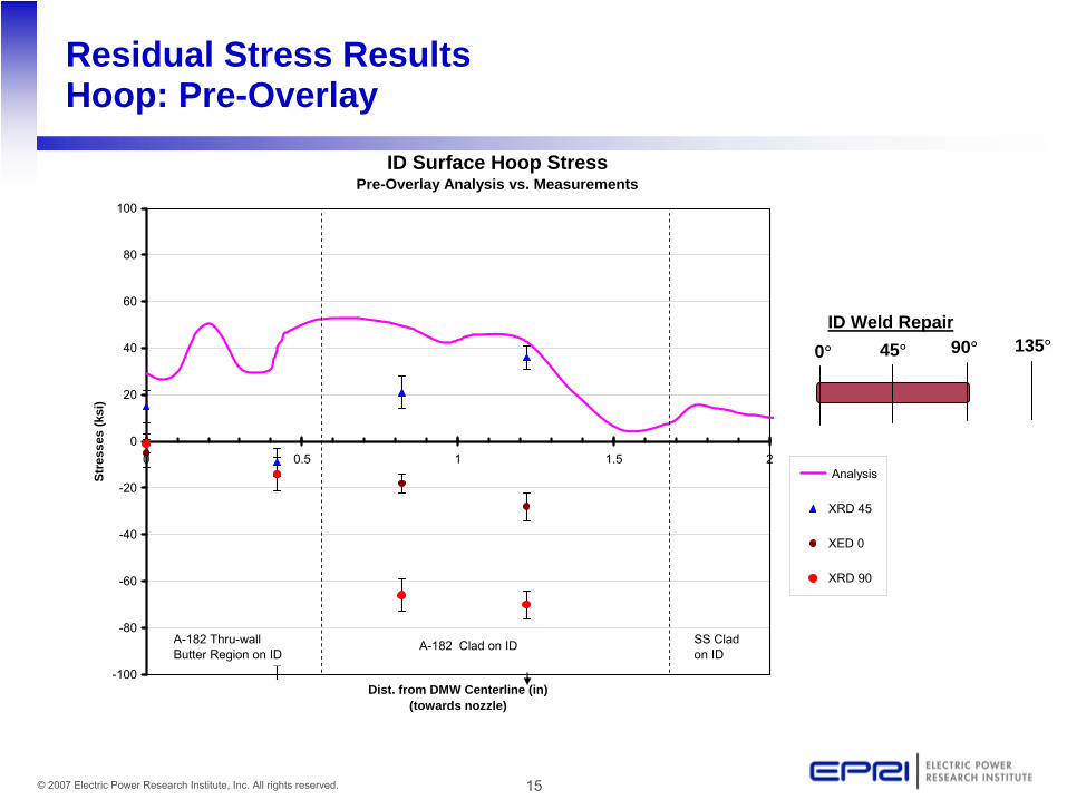
Residual Stress Results Hoop: Pre-Overlay
0° 45° 90° 135°ID Weld Repair
ID Surface Hoop StressPre-Overlay Analysis vs. Measurements
-100
-80
-60
-40
-20
0
20
40
60
80
100
0 0.5 1 1.5 2
Dist. from DMW Centerline (in)(towards nozzle)
Stre
sses
(ksi
)
Analysis
XRD 45
XED 0
XRD 90
A-182 Thru-wall Butter Region on ID
SS Clad on ID
A-182 Clad on ID

16© 2007 Electric Power Research Institute, Inc. All rights reserved.
Residual Stress Results Hoop: Post-Overlay
0° 45° 90° 135°ID Weld Repair
ID Surface Hoop StressPost-Overlay Analysis vs. Measurements
-100
-80
-60
-40
-20
0
20
40
60
80
100
0 0.5 1 1.5 2
Dist. from DMW Centerline (in)(towards nozzle)
Stre
sses
(ksi
)
Analysis
XRD 45
XRD 135
Hole Drill
A-182 Thru-wall Butter Region on ID
SS Clad on ID
A-182 Clad on ID

17© 2007 Electric Power Research Institute, Inc. All rights reserved.
MRP-169 – NRC Request for Additional Information (RAI)
•
Thirty (30) questions–
General comments (4)–
Inspections (8)–
Leak Before Break (2)–
Fatigue (2)–
Weld Overlay Effectiveness (3)–
Stress Analysis (6)–
Example Analysis (1)–
Clarifications (4)•
Draft initial RAI ‘plan of attack’
and ‘overarching issues summary’
provided to MRP in early May ‘07
•
MRP conference call held in early May ’07 to obtain concurrence on RAI response approach and project schedule

18© 2007 Electric Power Research Institute, Inc. All rights reserved.
MRP-169 – NRC RAI Project Schedule
Timeframe Milestone
Early June ‘07 Draft Final Responses for MRP Review and Comment
Early July ‘07 MRP Comment Resolution Close-Out and NRC (Draft) RAI Response Submittal
TBD MRP/NRC Staff Meeting to Present and Discuss Draft RAI Responses
TBD Finalize and Submit RAI Responses
TBD Revise and Resubmit MRP-169 for SER

19© 2007 Electric Power Research Institute, Inc. All rights reserved.
Summary of Overarching Issues
•
Inconsistencies in Post Overlay ISI Requirements–
MRP-169 vs. MRP-139 vs. (draft) Code Cases N-740-1 and N-754–
Optimized WOL provides stress improvement plus
structural and PWSCC resistance functionality. Therefore:•
MRP-139, Cat. B (not
Cat. C) should apply if pre-WOL inspection is conducted, found clean and optimized WOL applied;
•
MRP-139, Cat. F (not
Cat. G) should apply if pre-WOL inspection is not conducted, or found cracked and optimized WOL applied;
•
Technical basis statement to be developed to support position (similar to MRP-139, Section 6) and
formal ‘interim guidance’
obtained to reconcile with MRP-139
–
MRP does not
endorse the 25% sampling approach for future WOL inservice inspections addressed by Code Case N-740
–
MRP-139/-169 5-year subsequent inspection requirement to be maintained rather than 1st
or 2nd
outage subsequent inspection requirement of Code Case N-740

20© 2007 Electric Power Research Institute, Inc. All rights reserved.
Summary of Overarching Issues (Cont’d)
•
Optimized Overlays for Repair as well as Mitigation–
Repairs for nozzle welds with cracks of a prescribed thru-wall and circumferential dimension substantiated by design analysis
–
Allowance akin to that defined for MSIP (30% TW, 10% circumferential)
–
May permit use of Optimized WOL without pre-inspection•
Additional Qualification for Exams from ID Surface–
Preserve option of ID exams for Optimized WOL subsequent inspections
–
Requires further PDI qualification of ID exam for detection and sizing
of potential cracks in the compressive region of weld overlaid DMW
–
Mockup samples being developed for this purpose

21© 2007 Electric Power Research Institute, Inc. All rights reserved.
Summary of Overarching Issues (Cont’d)
•
LBB Re-Analysis Requirement –
Impact of WOL on LBB analyses must be evaluated (from technical and licensing standpoint)
•
Fatigue Crack Growth Evaluation Period–
Section III fatigue usage computations, the evaluation period is to the end of plant life, including license renewal where applicable
–
Fatigue crack growth evaluation is based on next scheduled exam

22© 2007 Electric Power Research Institute, Inc. All rights reserved.
Conclusion/Summary
•
MRP-169 will provide licensing basis for Optimized or reduced thickness WOLs
•
Clear path for resolution of NRC RAI has been established–
NRC approval requested consistent with first hot leg applications in Fall 2008
•
Application of Optimized WOL as a repair (vs. mitigation measure) is defensible based on its design basis and regulatory precedent for MSIP/IHSI
•
Interim MRP-139 guidance will be developed for Optimized WOL Category assignments

23© 2007 Electric Power Research Institute, Inc. All rights reserved.
Inspection Considerations
•
Project Overview•
Phase I –
2006
–
Objectives–
Results•
Phase II –
2007
–
Objectives–
Planned activities–
2007 Mitigation Objectives & Workscope•
Phase III -
2008
–
Proposed activities–
NDE Qualifications and Reporting•
Summary

24© 2007 Electric Power Research Institute, Inc. All rights reserved.
Project Overview
•
Closure of Inspection Gaps•
NDE of upper 50% of base material for optimized overlays
•
NDE of weld Overlay (WOL) over Cast SS•
Address tapered surface examinations and configurations
•
Address configurations requiring non-standard overlays
•
Residual stress measurements to confirm model

25© 2007 Electric Power Research Institute, Inc. All rights reserved.
Project Overview
•
Project is accomplished through three phases–
Phase I•
MRP funded in 2006 targeting the Pressurizer nozzles–
Phase II•
MEOG funded for 2007 targeting large diameter components
–
Phase III•
NDE Center funds in 2008•
NDE Technique development•
Documentation•
Demonstration•
Incorporation into ASME Code

26© 2007 Electric Power Research Institute, Inc. All rights reserved.
Pre-Emptive Weld Overlay Project – Phase I 2006
•
Funded by MRP -
2006•
Objectives;–
Pressurizer locations with and without WOL –
Pressurizer locations with and without Cast SS safe-ends–
Validation of Hot Isostatic Pressure (HIP) flaw process on Cast SS–
NDE of upper 50% of base material•
Results–
Mock ups complete (Full structural)–
Additional NDE analysis is being performed to validate results–
HIP process modifications will be considered for Phase II–
75% deep flaws were not detected•
Detected flaws which extend into WOL–
Current qualified PDI techniques are invalid on Cast SS w/ WOL–
NDE techniques and Equipment modifications are needed•
Working with vendors to improve

27© 2007 Electric Power Research Institute, Inc. All rights reserved.
Phase I Mock up Summary
Without WOL With WOL
System NSSS Location # of Mock ups reqd
# of Mock ups reqd
PZR CE Surge 0 1PZR CE Spray 0 1PZR CE Safety/Relief 2 2
Hot Leg CE Surge Line 0 0

28© 2007 Electric Power Research Institute, Inc. All rights reserved.
Pre-Emptive Weld Overlay Project – Phase II 2007
•
Funded by MEOG -
2007•
Objectives;–
Locations include; RCP Inlet/Outlet, Shut down Cooling, Drain Nozzles, Safety Injection•
With and without WOL•
FSWOLs
and OWOLs
to be evaluated–
Locations with Cast SS include; Surge, Safety/Relief, RCP, Safety Injection & Shutdown cooling
–
Validation of HIP process on heavy wall Cast SS–
NDE of upper 50% of base material•
Planned activities–
Analyze configuration data–
Finalize sample design–
Fabricate samples–
Stress and weld dilution measurements–
Perform QA and establish UT fingerprint baseline data–
Document limitations and develop resolution plans

29© 2007 Electric Power Research Institute, Inc. All rights reserved.
Phase II Mock up Summary
Without WOL With WOL
System NSSS Location # of Mock ups reqd
# of Mock ups reqd
Hot Leg CE Shutdown Cooling 1 1Hot Leg CE Drain Nozzles 2 2Cold Leg CE RCP In / Out 1 1Cold Leg CE Safety Injection 0 0Cold Leg CE Letdown/Drain Nz 0 0Cold Leg CE Charging Inlet / Spray 2 2
12 Total

30© 2007 Electric Power Research Institute, Inc. All rights reserved.
Mitigation Objectives 2007
•
Mitigation Project Objectives•
Include required design attributes
•
Hold points are set to allow collection of the required measurements needed to support design
•
Assure welding processes used were consistent with the current industry practices and planned applications in the field
•
Provide information to complete finite element analysis for large thick pipes

31© 2007 Electric Power Research Institute, Inc. All rights reserved.
2007 Mitigation Work Scope
•
Information needed for design and welding of large diameter thick cast components–
Overlay design•
Optimized overlay design
•
Full structural overlay design –
Verification of Stress Profile
–
Dilution Measurements•
Verification of Cr (%) (first 2 layers)
–
Shrinkage Data (per weld layer)•
Reporting and Data Collection

32© 2007 Electric Power Research Institute, Inc. All rights reserved.
Pre-Emptive Weld Overlay Project – Phase III 2008
•
Funded by EPRI (NDE) –
2008–
Proposed activities include:•
Additional technique development
•
Project documentation –
2007 results•
Complete demonstration activities
•
Integrate results into ASME code

33© 2007 Electric Power Research Institute, Inc. All rights reserved.
2008 NDE Qualifications & Report
•
Work Scope–
Develop Code criteria and relief requests needed to qualify NDE procedures for the examination of PWOL's
–
Develop and qualify examination procedures to address pre-emptive weld overlays
–
Develop and qualify examination procedures to examine overlays that cover cast SS components
–
Document stress/strain data, which will be used to support the design and application of pre-emptive weld overlays for large diameter, thick components

34© 2007 Electric Power Research Institute, Inc. All rights reserved.
Summary
•
Review of configuration data has indicated that additional mock-ups are needed to close inspection gaps–
Unique configurations•
Including tapers
•
Thickness/diameter changes–
Cast Components
–
Overlays•
Mitigation Committee needs additional data to support both;–
Full structural overlays of thick components
–
Optimized overlays of thick components