Practical work 4
34
EC202- Computer Aided Design PRACTICAL EVALUATION FORM NAME:………………………………………………………. CLASS.: ……………… REGISTRATION NO.: ……………………………………… PRACTICAL WORK: 4 APPLICATION OF AUTOCAD PACKAGE IN TECHNICAL AND ELECTRICAL DRAWINGS: THE EDIT/MODIFY COMMANDS AND DISPLAY CONTROLS No . Skill i. Accuracy ii. Within Time Frame Excellent (8-10 marks) Average (5-7 Marks) Weak (0-4 Marks) Total 1. Part A: Setting A4 Metric Measurement 2. Part B: Create Objects & Modify Commands Sub-Total /20 No . Report Total amy/khk/jke/puo EC4.1
-
Upload
wkhairil80 -
Category
Education
-
view
77 -
download
2
Transcript of Practical work 4

EC202- Computer Aided Design
PRACTICAL EVALUATION FORM
NAME:………………………………………………………. CLASS.: ………………
REGISTRATION NO.: ………………………………………
PRACTICAL WORK: 4
APPLICATION OF AUTOCAD PACKAGE IN TECHNICAL AND ELECTRICAL
DRAWINGS: THE EDIT/MODIFY COMMANDS AND DISPLAY CONTROLS
No.
Skill
i. Accuracy
ii. Within Time Frame
Excellent
(8-10 marks)
Average
(5-7 Marks)
Weak
(0-4 Marks)Total
1.Part A: Setting A4 Metric
Measurement
2.Part B: Create Objects &
Modify Commands
Sub-Total /20
No. Report Total
1. Discussion /4
2 Question /4
3. Reflection /2
Sub-Total /10
Total /30
amy/khk/jke/puo EC4.1

EC202- Computer Aided Design
PRACTICAL WORK: 4
TITLE : APPLICATION OF AUTOCAD PACKAGE IN TECHNICAL AND
ELECTRICAL DRAWINGS
COURSE LEARNING OUTCOME:
CLO 4: Apply the draw and edit/modify commands skillfully to produce
simple and complex technical drawings.
OBJECTIVES: The students should be able to:
1. Edit objects by using the Edit/Modify Commands such as Erase, Move,
Rotate, Break, Trim, Scale, Mirror, Array, Stretch, Extend, Fillet,
Chamfer, Offset, Divider, Measure, Change and Poly-Edit.
2. Draw and Edit simple and complex technical drawings by making use of
the Draw and Edit/Modify commands.
THEORY :
AutoCAD drawings are rarely completed simply by drawing lines, circles etc. Most likely
you will need to Modify these basic drawing objects in some way in order to create the
image you need. AutoCAD provides a whole range of modify tools such as Move, Copy,
Rotate and Mirror.
For easier editing, especially in more complex drawing, display controls such as the Zoom
and Pan commands are used. Depending on the selections made, they only change the views
but do not change the actual size.
EQUIPMENT : 1. Desktop Computer/Laptop
2. AutoCAD 2004 Software
amy/khk/jke/puo EC4.2
EC202- Computer Aided Design
PROCEDURE :
Part A: Drawing Setup
1. Start AutoCAD to begin drawing.
2. Create a new drawing space using the Metric measurement.
3. Set the drawing limits to A4 paper size.
4. Display the grid to the extent of the drawing limits.
Part B: Modify Commands
The Modify tools can be accessed in one of three ways:
i. Selecting the Modify commands from the Pull-down Menu <Modify>
Fig. 4.1: Pull-down Menu <Modify>
ii. Selecting the required icon from the Toolbar <Modify>
Fig. 4.2: Modify Toolbar
iii. Typing names or shortcuts at the Keyboard and press [Enter]
Fig. 4.3: Keyboard Entry
amy/khk/jke/puo EC4.3

EC202- Computer Aided Design
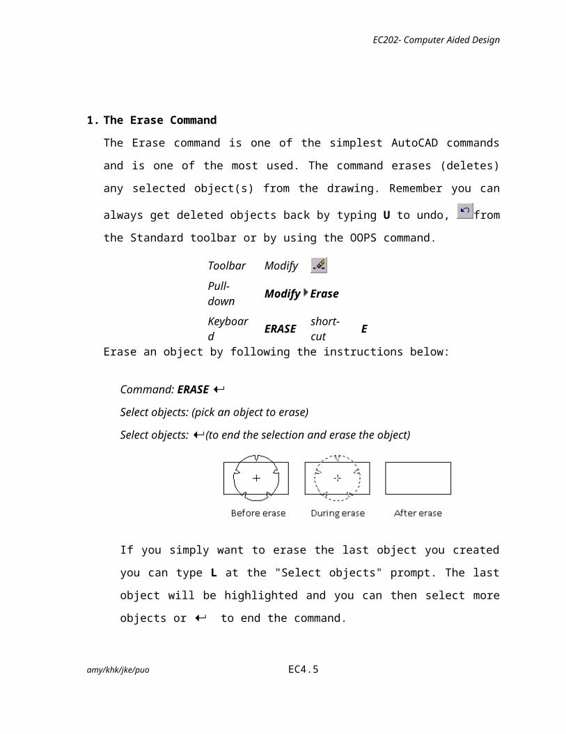
1. The Erase Command
The Erase command is one of the simplest AutoCAD commands and is one of the most
used. The command erases (deletes) any selected object(s) from the drawing. Remember
you can always get deleted objects back by typing U to undo, from the Standard
toolbar or by using the OOPS command.
Toolbar Modify
Pull-down Modify Erase
Keyboard ERASEshort-cut
E
Erase an object by following the instructions below:
Command: ERASE
Select objects: (pick an object to erase)
Select objects: (to end the selection and erase the object)
If you simply want to erase the last object you created you can type L at the "Select
objects" prompt. The last object will be highlighted and you can then select more
objects or to end the command.
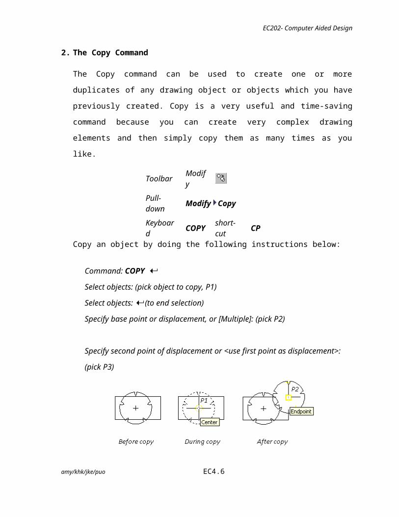
2. The Copy Command
The Copy command can be used to create one or more duplicates of any drawing object
or objects which you have previously created. Copy is a very useful and time-saving
command because you can create very complex drawing elements and then simply copy
them as many times as you like.
Toolbar Modify
Pull-down Modify Copy
amy/khk/jke/puo EC4.4
EC202- Computer Aided Design
Keyboard COPY short-cut CPCopy an object by doing the following instructions below:
Command: COPY
Select objects: (pick object to copy, P1)
Select objects: (to end selection)
Specify base point or displacement, or [Multiple]: (pick P2)
Specify second point of displacement or <use first point as displacement>:(pick P3)
The Multiple option allows you to create additional copies of the selected object(s) by
picking as many new points as you like. To end a multiple copy, just press the key.
3. The Move Command
The Move command works in a similar way to the Copy command except that no copy
is made, the selected object(s) is simply moved from one location to another.
Toolbar Modify
Pull-down Modify Move
Keyboard MOVE short-cut M
Move an object by following the instructions below:
Command: MOVE
Select objects: (pick object to move)
Select objects: (to end selection)
amy/khk/jke/puo EC4.5
EC202- Computer Aided Design
Specify base point or displacement: (pick P1)
Specify second point of displacement or <use first point as displacement>: (pick P2)
4. The Rotate Command
The Rotate command allows an object or objects to be rotated about a point selected by
the user. AutoCAD prompts for a second rotation point or an angle which can be typed
at the keyboard.
Toolbar Modify
Pull-down Modify Rotate
Keyboard ROTATE short-cut RO
Rotate the object by following the instructions below:
Command: ROTATE
Current positive angle in UCS: ANGDIR=counterclockwise ANGBASE=0
Select objects: (pick object to rotate)
Select objects: (to end selection)
Specify base point: (pick base point, P1)
Specify rotation angle or [Reference]: (pick second point, or enter angle)
amy/khk/jke/puo EC4.6
Note that as with the Copy command, the two pick points, P1 and P2 are used only to indicate the distance and direction of movement.

EC202- Computer Aided Design
Remember, by default, AutoCAD angles start at 3 o'clock and increase in an anti-
clockwise direction. The "ANGDIR" and "ANGBASE" variables remind you of this.
If you want to rotate in a clockwise direction you can enter a negative angle by using
a minus sign.
5. The Break Command
The Break command which enables you to break (remove part of) an object by defining
two break points, can be used with lines, polylines, circles, arcs ellipses, splines, xlines
and rays. When you break an object, you can either select the object using the first break
point or then pick the second break point, or you can select the object and then pick the
two break points.
Toolbar Modify
Pull-down Modify Break
Keyboard BREAK short-cut BR
Break the object by following the instructions below:
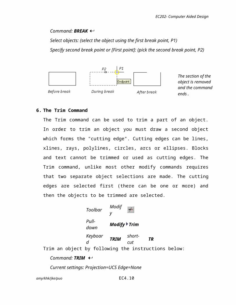
Command: BREAK
Select objects: (select the object using the first break point, P1)
Specify second break point or [First point]: (pick the second break point, P2)
6. The Trim Command
The Trim command can be used to trim a part of an object. In order to trim an object you
must draw a second object which forms the "cutting edge". Cutting edges can be lines,
xlines, rays, polylines, circles, arcs or ellipses. Blocks and text cannot be trimmed or
used as cutting edges. The Trim command, unlike most other modify commands requires
amy/khk/jke/puo EC4.7
The section of the object is removed and the command ends.

EC202- Computer Aided Design
that two separate object selections are made. The cutting edges are selected first (there
can be one or more) and then the objects to be trimmed are selected.
Toolbar Modify
Pull-down Modify Trim
Keyboard TRIM short-cut TRTrim an object by following the instructions below:
Command: TRIM
Current settings: Projection=UCS Edge=None
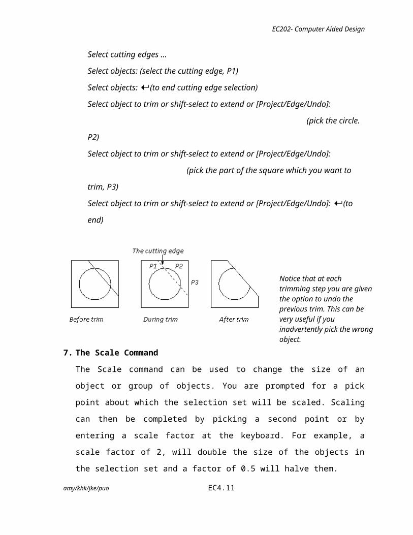
Select cutting edges ...
Select objects: (select the cutting edge, P1)
Select objects: (to end cutting edge selection)
Select object to trim or shift-select to extend or [Project/Edge/Undo]:
(pick the circle. P2)
Select object to trim or shift-select to extend or [Project/Edge/Undo]:
(pick the part of the square which you want to trim, P3)
Select object to trim or shift-select to extend or [Project/Edge/Undo]: (to end)
7. The Scale Command
The Scale command can be used to change the size of an object or group of objects. You
are prompted for a pick point about which the selection set will be scaled. Scaling can
then be completed by picking a second point or by entering a scale factor at the
keyboard. For example, a scale factor of 2, will double the size of the objects in the
selection set and a factor of 0.5 will halve them.
amy/khk/jke/puo EC4.8
Notice that at each trimming step you are given the option to undo the previous trim. This can be very useful if you inadvertently pick the wrong object.

EC202- Computer Aided Design
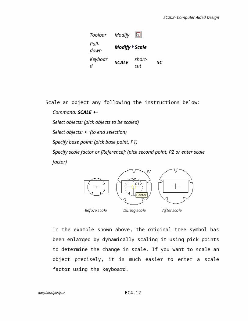
Toolbar Modify
Pull-down Modify Scale
Keyboard SCALEshort-cut
SC
Scale an object any following the instructions below:
Command: SCALE
Select objects: (pick objects to be scaled)
Select objects: (to end selection)
Specify base point: (pick base point, P1)
Specify scale factor or [Reference]: (pick second point, P2 or enter scale factor)
In the example shown above, the original tree symbol has been enlarged by
dynamically scaling it using pick points to determine the change in scale. If you want
to scale an object precisely, it is much easier to enter a scale factor using the
keyboard.
8. The Mirror Command
The Mirror command allows you to mirror selected objects in your drawing by picking
them and then defining the position of an imaginary mirror line using two points.
Toolbar Modify
Pull-down Modify Mirror
Keyboard MIRROR short-cut MI
amy/khk/jke/puo EC4.9
EC202- Computer Aided Design
Mirror an object by following the instructions below:
Command: MIRROR
Select objects: (pick object to mirror)
Select objects: (to end selection)
Specify first point of mirror line: (pick P12)
Specify second point of mirror line: (pick P1)
Delete source objects? [Yes/No] <N>: (for No to keep the original object)
Notice that in the command sequence above, pressing the key when asked
whether to "Delete source objects?" resulted in a "No" response. This is because
"No" is the default option. AutoCAD always shows the default option within
triangular brackets, in this case "<N>".
9. The Array Command
The Array command makes multiple copies of selected objects in a rectangular matrix
(columns and rows) or a polar (circular) pattern. It is now completely dialogue box
driven with the option to see a preview of the array before it is created. When creating
rectangular arrays it is important to remember that new rows are created above the
original object and new columns are created to the right of the original object. The
resulting array is, therefore, always created with the original object in the bottom left
hand position with respect to the current co-ordinate system.
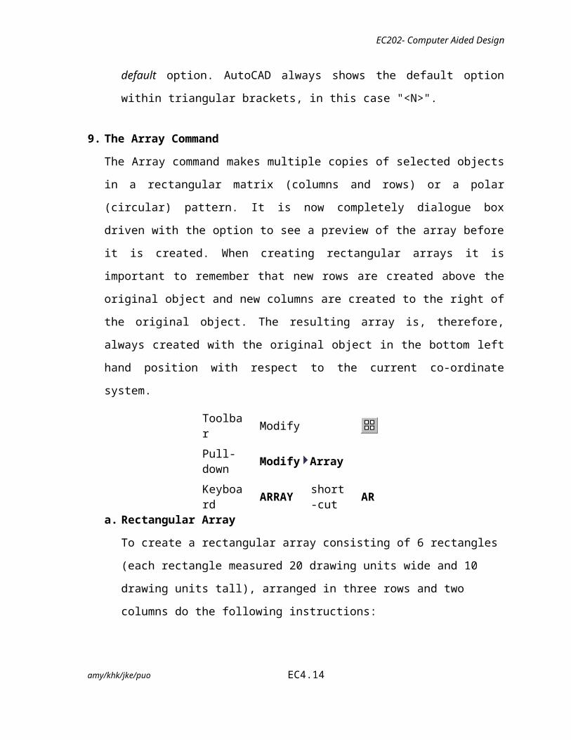
Toolbar Modify
Pull-down Modify Array
amy/khk/jke/puo EC4.10
EC202- Computer Aided Design
Keyboard ARRAYshort-cut
AR
a. Rectangular Array
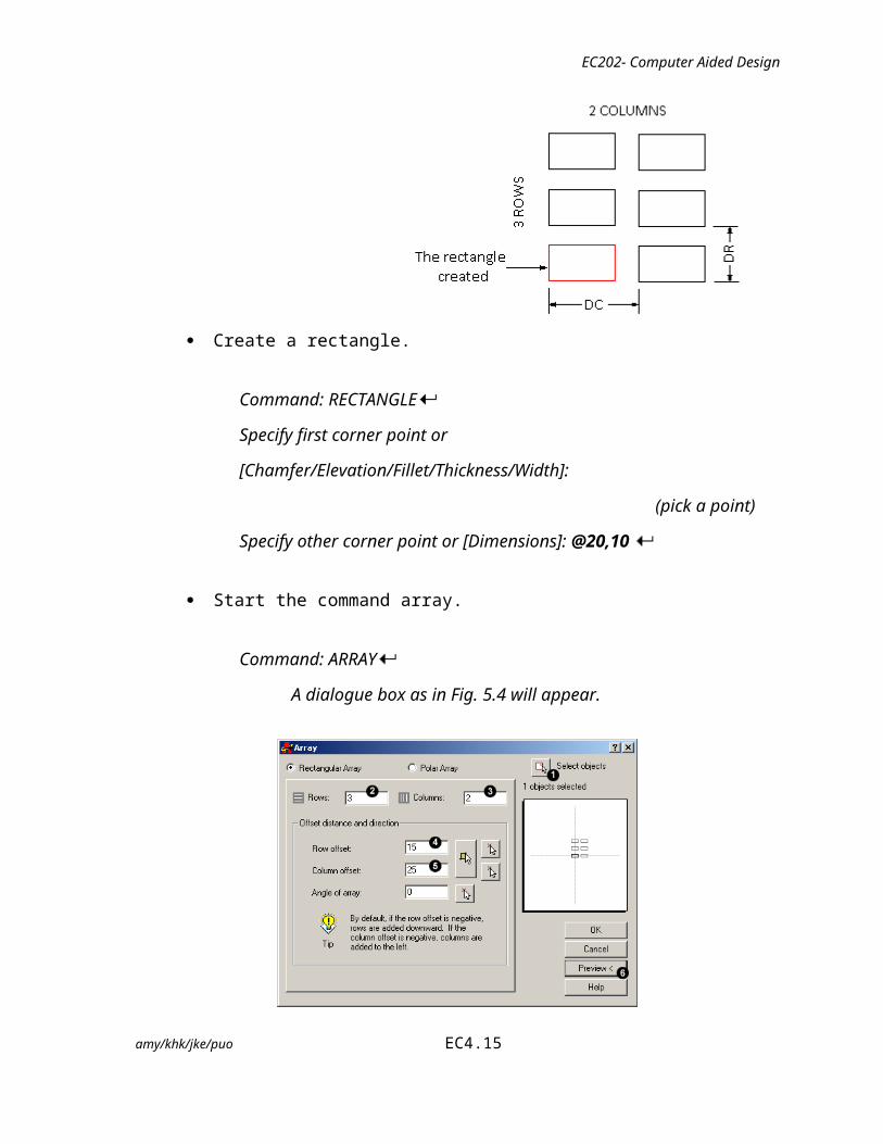
To create a rectangular array consisting of 6 rectangles (each rectangle measured 20
drawing units wide and 10 drawing units tall), arranged in three rows and two
columns do the following instructions:
Create a rectangle.
Command: RECTANGLE
Specify first corner point or [Chamfer/Elevation/Fillet/Thickness/Width]:
(pick a point)
Specify other corner point or [Dimensions]: @20,10
Start the command array.
Command: ARRAY
A dialogue box as in Fig. 5.4 will appear.
amy/khk/jke/puo EC4.11
EC202- Computer Aided Design
Fig. 4.4: Array Command selection <rectangular array>
Click for the Rectangular Array radio button and follow the steps below:
1. Click the Select objects button. The dialogue box will temporarily disappear
enabling you to select the rectangle you just drew. Press [Enter] on your
keyboard to complete the selection. You are now returned to the dialogue box
and the message immediately below the Select Objects button should read "1
objects selected".
2. Enter the number of rows required in the Rows edit box. For this example, enter
the value "3". Notice that the schematic preview on the right hand side of the
dialogue box updates to reflect the values you are entering.
3. Enter the number of columns required in the Columns edit box. Enter the value
"2".
4. Enter the row offset in the Row Offset edit box. This is the distance DR in the
illustration above. Note that this is not the distance between rows. In this
example, our rectangle is 10 units high and we will enter a row offset of 15. The
result will be a 5 unit gap between rectangles.
5. Enter the column offset in the Column Offset edit box. The same parameters
apply as for the row offset. Enter a value of 25 to give a 5 unit gap between our
rectangles.
amy/khk/jke/puo EC4.12

EC202- Computer Aided Design
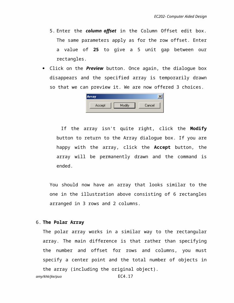
Click on the Preview button. Once again, the dialogue box disappears and the
specified array is temporarily drawn so that we can preview it. We are now offered 3
choices.
If the array isn't quite right, click the Modify button to return to the Array
dialogue box. If you are happy with the array, click the Accept button, the array
will be permanently drawn and the command is ended.
You should now have an array that looks similar to the one in the illustration above
consisting of 6 rectangles arranged in 3 rows and 2 columns.
6. The Polar Array
The polar array works in a similar way to the rectangular array. The main difference is
that rather than specifying the number and offset for rows and columns, you must
specify a center point and the total number of objects in the array (including the original
object).
To create a polar array consisting of a original rectangle and being copied 6 times
through a center point C, through an angle of 360 degrees (full circle), do the following
instructions:
Create a rectangle, similar to one drawn in the rectangular array above.
Start the Array command
Command: ARRAY A dialogue box as in Fig. 5.4 will appear.amy/khk/jke/puo EC4.13
EC202- Computer Aided Design
Fig. 4.5: Array Command selection <Polar array>
Click the Polar Array radio button and follow the steps below:
1. Click the Select objects button. The dialogue box will temporarily disappear
enabling you to select the rectangle you just drew. Press the [Enter] on your
keyboard to complete the selection. You are now returned to the dialogue box and
the message immediately below the Select Objects button should read "1 objects
selected".
2. Specify the center point for the array. This is the point C in the illustration above.
You can do this, either by entering x and y co-ordinates into the appropriate edit
boxes if you know what these values should be, or click the Pick Center Point
button to pick a point from the drawing area. Pick a point somewhere below the
rectangle you have just drawn.
3. Enter a value for the total number of items. For this example, enter the value "6".
Notice that once again, the schematic preview updates to reflect the values you have
entered.
4. Make sure that the Rotate items as copied checkbox is checked.
5. Click on the Preview button. Once again, the dialogue box disappears and the
specified array is temporarily drawn so that we can preview it. We are now offered 3
choices as stated in the Rectangular array command.
amy/khk/jke/puo EC4.14
EC202- Computer Aided Design
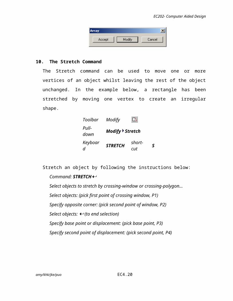
10. The Stretch Command
The Stretch command can be used to move one or more vertices of an object whilst
leaving the rest of the object unchanged. In the example below, a rectangle has been
stretched by moving one vertex to create an irregular shape.
Toolbar Modify
Pull-down Modify Stretch
Keyboard STRETCHshort-cut
S
Stretch an object by following the instructions below:
Command: STRETCH
Select objects to stretch by crossing-window or crossing-polygon...
Select objects: (pick first point of crossing window, P1)
Specify opposite corner: (pick second point of window, P2)
Select objects: (to end selection)
Specify base point or displacement: (pick base point, P3)
Specify second point of displacement: (pick second point, P4)
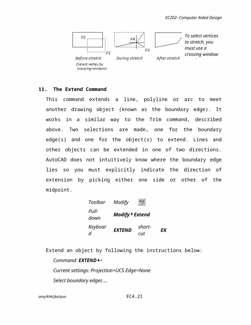
11. The Extend Command
This command extends a line, polyline or arc to meet another drawing object (known as
the boundary edge). It works in a similar way to the Trim command, described above. amy/khk/jke/puo EC4.15
To select vertices to stretch, you must use a crossing window or polygon.

EC202- Computer Aided Design
Two selections are made, one for the boundary edge(s) and one for the object(s) to
extend. Lines and other objects can be extended in one of two directions. AutoCAD does
not intuitively know where the boundary edge lies so you must explicitly indicate the
direction of extension by picking either one side or other of the midpoint.
Toolbar Modify
Pull-down Modify Extend
Keyboard EXTEND short-cut EX
Extend an object by following the instructions below:
Command: EXTEND
Current settings: Projection=UCS Edge=None
Select boundary edges ...
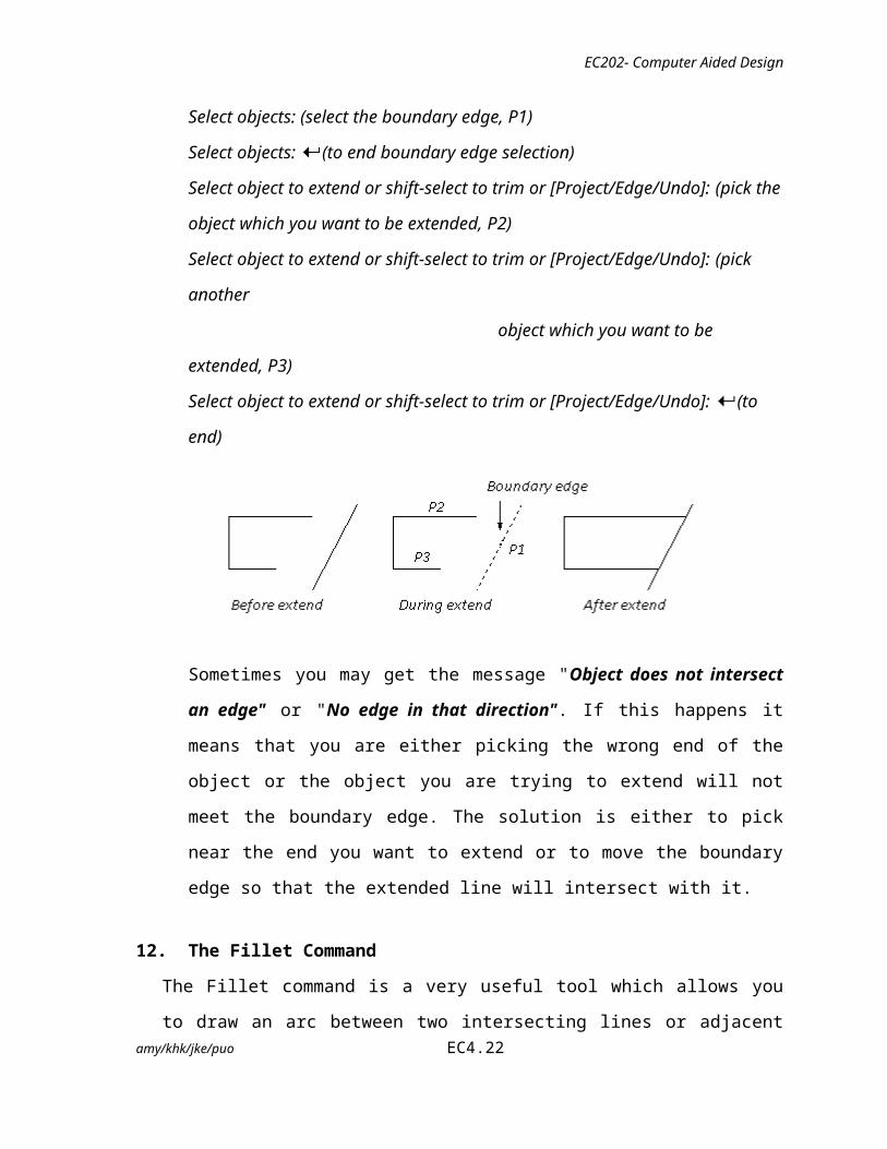
Select objects: (select the boundary edge, P1)
Select objects: (to end boundary edge selection)
Select object to extend or shift-select to trim or [Project/Edge/Undo]: (pick the
object which you want to be extended, P2)
Select object to extend or shift-select to trim or [Project/Edge/Undo]: (pick another
object which you want to be extended, P3)
Select object to extend or shift-select to trim or [Project/Edge/Undo]: (to end)
Sometimes you may get the message "Object does not intersect an edge" or "No
edge in that direction". If this happens it means that you are either picking the
wrong end of the object or the object you are trying to extend will not meet the
boundary edge. The solution is either to pick near the end you want to extend or to
move the boundary edge so that the extended line will intersect with it.
amy/khk/jke/puo EC4.16
EC202- Computer Aided Design
12. The Fillet Command
The Fillet command is a very useful tool which allows you to draw an arc between two
intersecting lines or adjacent polyline segments. You first need to use the command to
set the required radius and then a second time to select the two lines.
Toolbar Modify
Pull-down Modify Fillet
Keyboard FILLET short-cut F
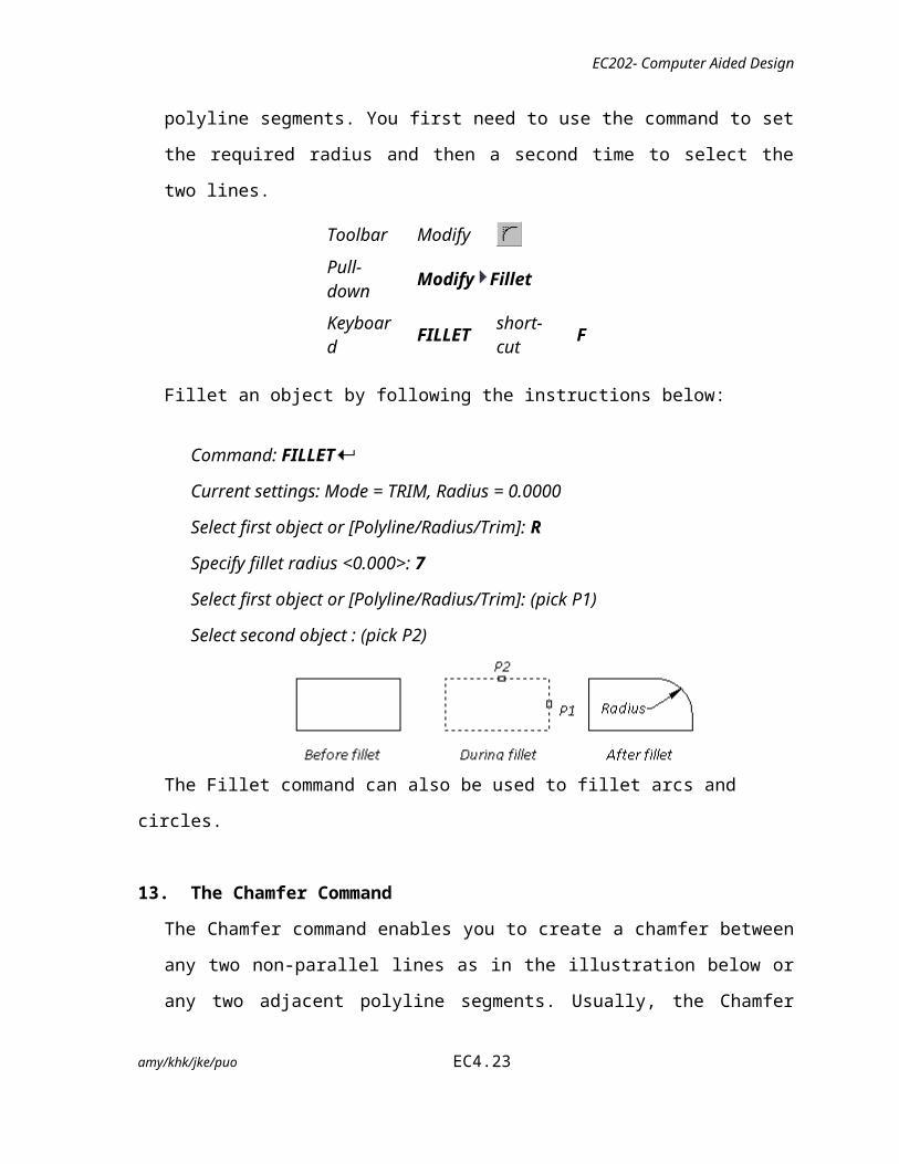
Fillet an object by following the instructions below:
Command: FILLET
Current settings: Mode = TRIM, Radius = 0.0000
Select first object or [Polyline/Radius/Trim]: R
Specify fillet radius <0.000>: 7
Select first object or [Polyline/Radius/Trim]: (pick P1)
Select second object : (pick P2)
The Fillet command can also be used to fillet arcs and circles.
13. The Chamfer Command
The Chamfer command enables you to create a chamfer between any two non-parallel
lines as in the illustration below or any two adjacent polyline segments. Usually, the
Chamfer command is used to set the chamfer distances before drawing the chamfer.
Toolbar Modify
Pull-down Modify Chamfer
Keyboard CHAMFER short-cut CHA
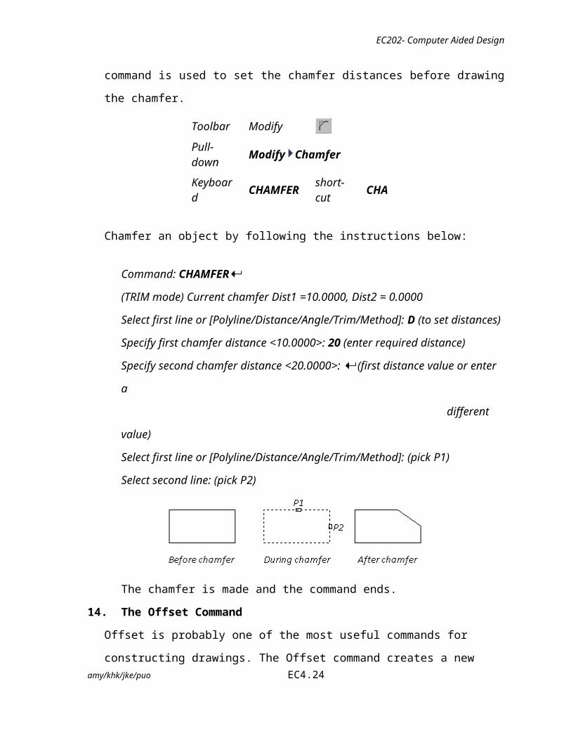
Chamfer an object by following the instructions below:
amy/khk/jke/puo EC4.17

EC202- Computer Aided Design
Command: CHAMFER
(TRIM mode) Current chamfer Dist1 =10.0000, Dist2 = 0.0000
Select first line or [Polyline/Distance/Angle/Trim/Method]: D (to set distances)
Specify first chamfer distance <10.0000>: 20 (enter required distance)
Specify second chamfer distance <20.0000>: (first distance value or enter a
different value)
Select first line or [Polyline/Distance/Angle/Trim/Method]: (pick P1)
Select second line: (pick P2)
The chamfer is made and the command ends.
14. The Offset Command
Offset is probably one of the most useful commands for constructing drawings. The
Offset command creates a new object parallel to or concentric with a selected object.
The new object is drawn at a user defined distance (the offset) from the original and in a
direction chosen by the user with a pick point. You can offset lines, arcs, circles,
ellipses, 2D polylines, xlines, rays and planar splines.
Toolbar Modify
Pull-down Modify Offset
Keyboard OFFSET short-cut O
Offset an object by doing the following command.
Command: OFFSET
Specify offset distance or [Through] <0.0000>: 5 (specify distance)
Select object to offset or <exit>: (select object, P1)
Specify point on side to offset: (pick direction, P2)
Select object to offset or <exit>: (to end or select another object to offset)
amy/khk/jke/puo EC4.18
EC202- Computer Aided Design
In the illustration below, a line has been offset to the right through a distance
"Offset" by picking a point to the right of the original line. The result is a new line to
the right of the original.
Circles can be offset inside or outside of themselves to create a new circle which is
concentric (has the same centre point) with the original circle. In the illustration, a
new circle has been created outside of the original by picking a point outside of the
original circle. The radius of the new circle is the offset distance "Offset" plus the
radius of the original circle.
15. The Divider Command
Divide marks off a specified number of equal lengths on a selected object by placing
point objects or blocks along the length, perimeter of the object. The objects that yuo can
divide include arcs, circles, ellipses an elliptical ars., polylines and splines.
Toolbar Divide
Pull-down Draw Point Divide
Keyboard DIVIDEshort-cut
DIV
Divide the object by following the instructions below:
Command: DIVIDE
Select object to divide: (pick the line P1)
Enter the number of segments or [Block]: 7
amy/khk/jke/puo EC4.19
EC202- Computer Aided Design
AutoCAD places a point between each segment. Note that you have to change the
suitable point style to make the points visible on your drawing.
16. The Measure Command
The Measure commands enable you to mark an object at specified intervals. You can
mark the intervals with either points or blocks. The last segment of a measured object
may be shorter than the interval you specify.
Toolbar Measure
Pull-down Draw Point Measure
Keyboard MEASURE short-cut ME
Measure an object by following the instructions below:
Command: MEASURE
Select object to measure: (pick Line P1)
Specify length of segment or [Block]: 10
AutoCAD places points on the object at the specified intervals.
17. The Change Command
Change command enables you to change the selected objects and modifiers properties of
existing objects. The result depends on the type of objects you select.
Toolbar -none-
Pull-down Modify Properties
Keyboard CHANGEshort-cut
-
amy/khk/jke/puo EC4.20
EC202- Computer Aided Design
There are two options in Change command; either change points or properties.
a. The Change command below shows how to move the endpoints of the selected line
to a new point. Follow the instructions below.
Change : CHANGE
Select object: (pick a line, P1)
Specify change point or [Properties]: (pick a new point P2 or determine the
required new coordinate point)
b. The change command below can also modifies properties of existing objects such as
color, elevation, layer, Ltype, LtScale, lineweight and thickness. Follow the
instructions below to change the lineweight of the line.
Command: CHANGE
Select object: (pick a line)
Specify change point or [Properties]: P
Enter Property to change [Color/Ele/LType/ItScale/LWeight/thickness]:C
Enter New color <varies>: red
Enter Property to change [Color/Ele/LType/ItScale/LWeight/thickness]:
18. The Poly-edit Command
The Poly-edit command can be used to edit Polylines by closing and opening them and
by moving, adding or deleting individual vertices. You can straighten the polyline
between any two vertices and toggle the linetype so that a dash appears before and after
each vertex. You can set a uniform width for the entire polyline or control the width of
each segment.
Toolbar Modify 11amy/khk/jke/puo EC4.21
EC202- Computer Aided Design
Pull-down Modify Object Polyline
Keyboard PEDIT short-cut -a. To close a polyline by following the instructions below:
Command: PEDIT
Select polyline or [Multiple]: (pick the polyline)
Enter an option [Close/Join/Width/Edit vertex/Fit/Spline/Decurve/Ltype gen/
Undo]: C
Enter an option [Open/Join/Width/Edit vertex/Fit/Spline/Decurve/Ltype gen/
/Undo]:
b. To change the width of the polyline by following the instructions below:
Command: PEDIT
Select polyline or [Multiple]:
Object selected is not a polyline
Do you want to turn it into one? <Y>
Enter an option [Close/Join/Width/Edit vertex/Fit/Spline/Decurve/Ltype gen/Undo]:
W
Specify new width for all segments: 2
Enter an option [Close/Join/Width/Edit vertex/Fit/Spline/Decurve/Ltype gen/Undo]:
(to end)
PART B: Control Display commands
amy/khk/jke/puo EC4.22
EC202- Computer Aided Design
You can change the magnification of a view by zooming in and out. Like zooming in and
out with a camera, ZOOM does not change the absolute size of objects in the drawing; it
changes only the magnification of the view.
1. Zoom Command
The Zoom command increases or decreases the apparent size of objects in the current
viewport. You cannot use ZOOM transparently during VPOINT or DVIEW or while
ZOOM, PAN, or VIEW in progress.
Toolbar Zoom
Pull-down View Zoom
Keyboard ZOOMshort-
cutZ
Zoom the views by following the instruction below:
Command: Z <ENTER> ZOOM
Specify corner of window, enter a scale factor (nX or nXP), or
[All/Center/Dynamic/Extents/Previous/Scale/Window/Object] <real time>:
2. Pan Command
The Pan command moves the view in the current viewport. It does not change the
location or magnification of objects on your drawing; it changes only the view.
Toolbar Zoom
Pull-down View Pan Realtime
Keyboard none
To Pan by dragging:
Select Pan Realtime from the Pull-Down menu <View>.
When the hand cursor appears, drag the view by holding down the button as you
move the pointing device.
If you are using an IntelliMouse, hold down the wheel button and move the mouse. amy/khk/jke/puo EC4.23
(2 Marks)
(2 Marks)
EC202- Computer Aided Design
3. The Redraw Command
The redraw command refreshes the display in the current viewport, removing marker
blips and display artifacts (stray pixels) left by editing commands.
Command: REDRAW
4. The Regen Command
The Regen commands regenerates the entire drawing from the current viewport and
recomputes the screen coordinates for all objects in the current viewport. It also
reindexes the drawing database for optimum display and object selection performance.
Command: REGEN
Although the functionality appears to be similar, the REDRAW and REGEN commands are
significantly different.
The REDRAW command works significantly faster than the REGEN command.
DISCUSSIONS:
1. What is the difference between the Break command and Trim Command?
…………………………………………………………………………………………
…………………………………………………………………………………………
…………………………………………………………………………………………
…………………………………………………………………………………………
2. Explain the difference between Zoom Extent and Zoom Window.
…………………………………………………………………………………………
…………………………………………………………………………………………
amy/khk/jke/puo EC4.24

(2 Marks)
(1 Marks)
(3 Marks)
EC202- Computer Aided Design
…………………………………………………………………………………………
…………………………………………………………………………………………
QUESTIONS:
1. The Modify command <copy> duplicates its object.
Name three (3) other Modify commands that can also create duplication of its object.
i. …………………………………….
ii. …………………………………….
iii. …………………………………….
2. What Modify command can change the colour of the object drawn?
………………………………………………………………………………………
REFLECTION:
At the end of this practical work, I have learnt that:
…………………………………………………………………………………………………
…………………………………………………………………………………………………
…………………………………………………………………………………………………
…………………………………………………………………………………………………
amy/khk/jke/puo EC4.25