Practical Use Case Guide - The UML, SOA, BPMN, EA and...
20
Practical Use Case Guide Author: Softeam Consulting Team Supervised by Philippe Desfray Version: 1.0 Copyright: Softeam Softeam 21 avenue Victor Hugo 75016 Paris www.softeam.fr Objecteering Practical Guides
Transcript of Practical Use Case Guide - The UML, SOA, BPMN, EA and...

Practical Use Case Guide
Author: Softeam Consulting Team Supervised by Philippe Desfray
Version: 1.0
Copyright: Softeam
Softeam
21 avenue Victor Hugo
75016 Paris
www.softeam.fr
Objecteering Practical Guides
Practical Use Case Guide
Copyright Softeam 2008 21 avenue Victor Hugo, 75016 Paris
Page 2/20
Introduction to Practical Guides This set of Practical Guides is the result of hands-on experience gained by Softeam consultants.
Each guide is designed to facilitate model construction and to help you get the most out of the
Objecteering tool in a given context. The practical guides are deliberately short, since the aim is
to provide essential practical information in just a few pages. The Softeam consulting team
(www.softeam.fr) is at your service to help you with enterprise architecture definition, business
process and software architecture modeling, SOA, and to provide any other assistance you may
need in your IT projects.
In partnership with Objecteering Software, a consulting/tool package is available. Find out more
at www.objecteering.com or www.softeam.fr.
At www.objecteering.com, you can download the following user-friendly and unlimited tools
completely free of charge:
Objecteering NEXT UML Free Edition for UML modeling
Objecteering NEXT SOA Free Edition for business modeling: Enterprise Architecture, BPM,
SOA logical architecture, software architecture.
At www.objecteering.com, you can also evaluate and purchase Objecteering Enterprise Edition,
and discover the full functional richness of this tool: teamwork support, goal analysis, dictionary
definition, requirements analysis, code generation, documentation generation throughout the
entire project lifecycle, and so on.
The Practical Guides currently available are as follows:
Practical Use Case Guide
Practical Business Process Guide
Enterprise Architecture: Practical Guide to Logical Architecture
Practical Company Organization Modeling Guide
Other practical guides will be available soon. Please check our website for details.

Practical Use Case Guide
Copyright Softeam 2008 21 avenue Victor Hugo, 75016 Paris
Page 3/20
What are use cases? A UML use case model describes and formalizes relationships between the software system to be
developed and the outside world.
Use case models describe an external point of view (black box) and never deal with the internal
structure of the software. The aim is to specify the boundaries of the system and the different
interactions implemented in the realization of business requirements.
Use case models are made up of two main types of UML element – Actors and Use Cases (see
figure below). The container that appears in the diagram (in rectangular form) represents the
system. Use cases are presented inside the system and actors outside it.
Example of a use case with one actor and three use cases
Often used during the initial phases of the development process, use case models are a basic tool
used to formalize functional requirements. They are particularly helpful during dialog with users.
Practical Use Case Guide
Copyright Softeam 2008 21 avenue Victor Hugo, 75016 Paris
Page 4/20
Actors An actor is an entity outside the system that needs to directly interact with it. An actor can
represent a human user or any material or software device.
Examples: User, Client, Invoicing Software Application, Production Machine.
An actor represents a role played in the context of the system. A physical user can play several
different roles successively depending on how the system is used.
For example, a systems administrator is in charge of installing the latest version of a training
course in a classroom. He will first play his usual role (Administrator Actor) during the actual
installation of the new version on the training machines, before connecting as a student (Student
Actor) in order to check that the new version is working properly. In this case, there is only one
concrete external entity, the systems administrator. However, there are two distinct actors – the
administrator and the student.
In a use case model, the aim is to identify all the actors that interact with the system, both the
main actors (those which justify the construction of the system) and the secondary actors
necessary to the smooth running of the system (administrators, repair staff, and so on).
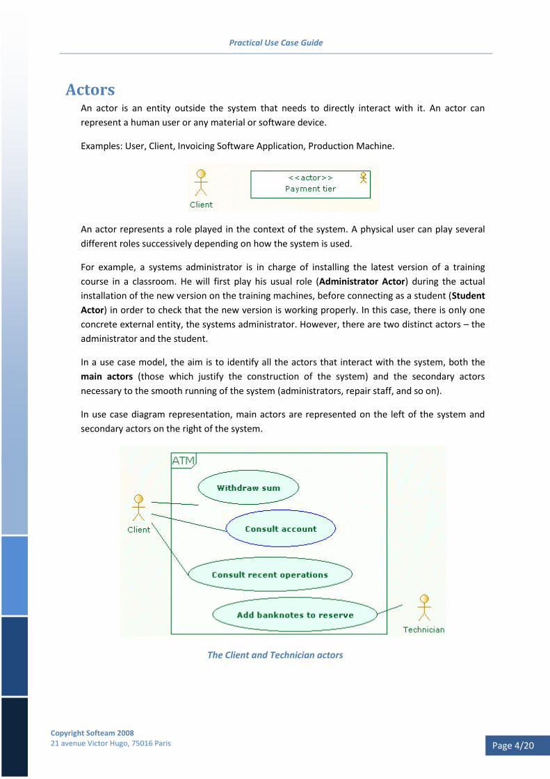
In use case diagram representation, main actors are represented on the left of the system and
secondary actors on the right of the system.
The Client and Technician actors
Practical Use Case Guide
Copyright Softeam 2008 21 avenue Victor Hugo, 75016 Paris
Page 5/20
In the example above, the technician responsible for regularly replenishing the stock of
banknotes (secondary actor) is absolutely essential and has an important impact on the design of
the ATM.
Validation rule
Every actor must be linked to at least one use case.

Practical Use Case Guide
Copyright Softeam 2008 21 avenue Victor Hugo, 75016 Paris
Page 6/20
Use cases A use case represents an interaction between actors and the system, with the aim of meeting a
fundamental requirement. It is described by a set of scenarios that specify the dialog between
the system and the actors.
A use case must render a real and complete service that provides the actor with an added value.
This is its essential characteristic. Conversely, functions such as "Enter PIN code" or "Choose
amount" are probably not use cases.
A use case is an atomic element, which must meet the following criteria:
Unicity of time. A scenario must play out in a relatively short timespan. Conversely, an
interaction cannot last several months.
Unicity of place. A scenario must take place in only one place (it cannot begin in the office
and finish at home, for example).
Unicity of actor (one beneficiary actor). The service is rendered for a single actor (main
actor), which is often the source that triggers the use case. Other actors who interact with
the use case are secondary actors. They take part in the scenarios but are not the
beneficiaries of the service.
Non-interruptible. A scenario cannot be interrupted and then continued later (in normal
usage). The scenario stops once the service has been rendered. Typically, an actor will not
"take a vacation" while a scenario is playing out.
The above criteria emphasize the atomic nature of use cases. They are not formal criteria, but
they do help in understanding, constructing and validating use cases. They also enable use cases
to be distinguished from other types of element, such as business processes, operations or
functions.
Tip: The following quick test is often used to check the essential criterion (must render a
real and complete service). Imagine that the actor stops just after the end of the
scenario. If the result is ridiculous, then there is probably an identification error. For
example, if we consider the "log on" scenario, which consists of entering your login
and password, if the user leaves the room to do something else, this would not make
much sense. The "log on" use case would not be retained.
Validation rules
Every use case must be linked to at least one actor(*).
Every use case must contain at least one scenario.
(*) Except for "false use cases" (see "Relationships between use cases").

Practical Use Case Guide
Copyright Softeam 2008 21 avenue Victor Hugo, 75016 Paris
Page 7/20
Scenarios A use case's scenarios make up a sequence that describes the dialog between the system and one
or several actors.
Scenarios are most often expressed textually. However, there are no rules in the UML standard
regarding this point. For example, activity diagrams, sequence diagrams or any other means can
also be used to express scenarios.
For a use case, there must be at least one main (or nominal) scenario, which represents the use
case's most meaningful interaction (sequence where "everything goes smoothly"). Other
scenarios can be added to describe other possible interactions.
Example:
1) The CLIENT inserts his bank card 2) The system asks the CLIENT to enter his PIN code [E1] 3) The CLIENT enters his PIN code [E2] 4) The system checks the CLIENT's PIN code 5) The system asks the CLIENT to enter the sum to withdraw 6) The CLIENT enters the sum 7) The system returns the bank card. The CLIENT takes his bank card 8) The system delivers banknotes corresponding to the sum to withdraw 9) The CLIENT takes his banknotes
Errors, exceptions and special cases can be added to scenarios in the form of links associated with
a particular sequence.
Examples:
E1: If the client does not enter his PIN code within 10 seconds, the system
returns the bank card and stops the scenario.
E2: If the client enters an incorrect PIN code, the system requests the
correct code once again. If the PIN code entered is still incorrect after
three attempts, the system stops the scenario and retains the bank card.

Practical Use Case Guide
Copyright Softeam 2008 21 avenue Victor Hugo, 75016 Paris
Page 8/20
Scenario represented by a note associated with the use case
In practice, most use cases are described by a scenario (nominal with links for errors and
exceptions).
The notion of scenario does not exist in UML. We recommend that you create an interaction to
the use case to represent the scenario.
Sequence diagrams (linked to the interaction) can be used to model the scenario. In practice,
most scenarios are simply described textually through "description" notes in Objecteering.
Defining a scenario in Objecteering

Practical Use Case Guide
Copyright Softeam 2008 21 avenue Victor Hugo, 75016 Paris
Page 9/20
Scenarios must not include GUI (Graphical User Interface) directions or technical elements:
Recommended Forbidden
The operator requests the list of files. The
system returns the list of open files.
The operator clicks on the "List" button. The
system displays the list in green in the
"files" window.
The system records the member's profile. The system writes the profile of the
member in the Oracle 8.1 database using an
SQL INSERT statement.
Practical Use Case Guide
Copyright Softeam 2008 21 avenue Victor Hugo, 75016 Paris
Page 10/20
Detailed use case file As well as scenarios, every use case is described by a detailed file containing a set of
characteristics:
Expected service
Pre-condition
Post-condition
Non-functional constraints
Applicable business rules
Running frequency
This list is not exhaustive and can be adapted and enriched in accordance with the realities of the
project or the terms usually employed (see A. Cockburn. Writing Effective Use Cases. Addison-
Wesley Longman Publishing Co).
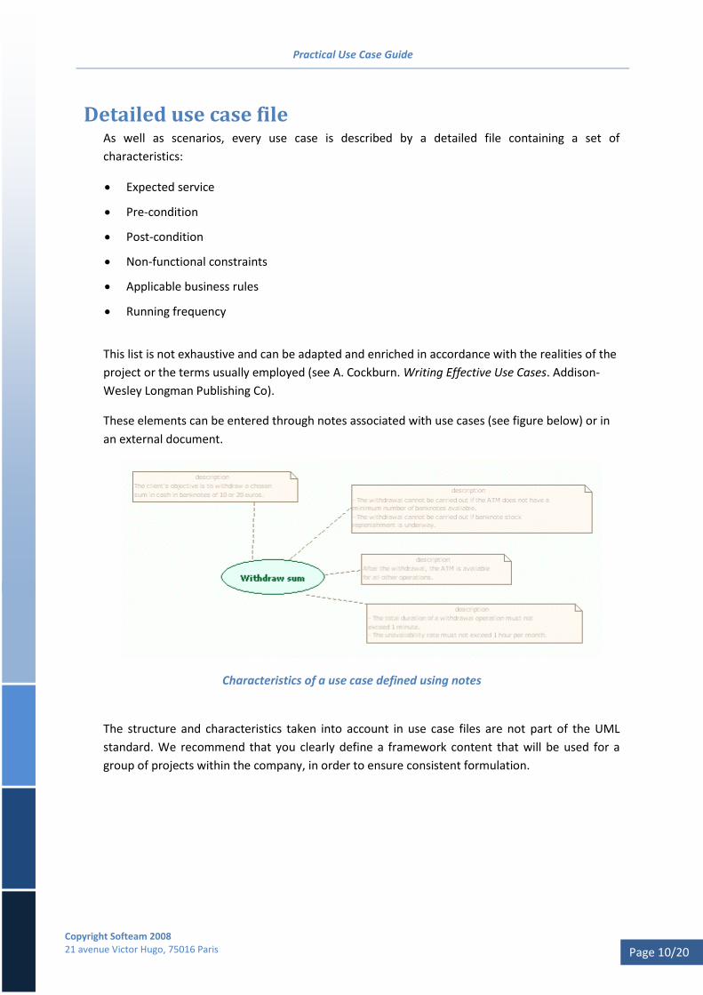
These elements can be entered through notes associated with use cases (see figure below) or in
an external document.
Characteristics of a use case defined using notes
The structure and characteristics taken into account in use case files are not part of the UML
standard. We recommend that you clearly define a framework content that will be used for a
group of projects within the company, in order to ensure consistent formulation.
Practical Use Case Guide
Copyright Softeam 2008 21 avenue Victor Hugo, 75016 Paris
Page 11/20
By default, Objecteering provides the following note types for use cases:
Description
Pre-Conditions
Post-Conditions
Exceptions
Functional Constraints
Non-Functional Constraints
Expected service For every use case, a description of the service expected by the actor who is the beneficiary of
the service.
Example:
The client's objective is to withdraw a chosen sum in cash (notes in euros) from his current
account.
Pre and post-conditions Pre-conditions describe the conditions that must be respected before a scenario can be triggered.
Example:
The withdrawal cannot be carried out if the ATM does not have a minimum number of
banknotes available.
The withdrawal cannot be carried out if banknote stock replenishment is underway.
Post-conditions describe the conditions checked after a scenario has stopped (except in the case
of errors or exceptional processing).
Example:
After the withdrawal, the ATM is available for all other operations
Other pre and post conditions can be defined for each scenario, in order to define specific
conditions that must be met.

Practical Use Case Guide
Copyright Softeam 2008 21 avenue Victor Hugo, 75016 Paris
Page 12/20
Non-functional constraints Non-functional constraints specify a set of additional requirements. These requirements are
linked to performance, availability, size, runtime, and so on.
Examples:
The total duration of a withdrawal operation must not exceed 1 minute.
The unavailability rate must not exceed 1 hour per month.
Elaborating a use case model Use case models are elaborated in close collaboration with IT services (business and user
aspects). Different business resources, dictionaries or requirement lists can be used (if they exist)
without being considered as unique sources of knowledge. The Objecteering Scope Manager
module is used to define and model requirements and to trace them to the rest of the model,
notably use cases. For every functional requirement, it must be determined whether it
corresponds to a use case (see the previously provided rules).
If you have a business process model (see the process modeling user guide), all identified
activities that are supported by the system are candidates to become use cases.
The necessary dialog takes place using whatever means is best adapted to the situation, with the
accent on direct communication (meetings, workshops, sketches, and so on).

Practical Use Case Guide
Copyright Softeam 2008 21 avenue Victor Hugo, 75016 Paris
Page 13/20
Use cases can also be used as a support without imposing UML formalism, if participants are
reticent. For example, textual scenarios can be exchanged as is, without the UML use case
diagrams.
On the whole, this elaboration will be carried out progressively using a breadth-first schema
rather than a depth-first schema. This means we can avoid breaking work down according to an
element-driven order (first the actors, then the use cases and finally the scenarios). Actors, use
cases and scenarios are closely linked and are constructed alongside one another.
Depending on the volume (number of use cases), it is better to break work down according to the
priority assigned to each use case (first the client-oriented use cases, linked to the main actors),
all the while continuing to communicate with IT services. The aim is to gradually converge on a
consistent, valid model that is consistent with the business vision.
General approach for elaborating use cases
During the elaboration of initial models, we recommend against using relationships between use
cases (incude, extend or inheritance). Scenarios should be used instead.

Practical Use Case Guide
Copyright Softeam 2008 21 avenue Victor Hugo, 75016 Paris
Page 14/20
Identifying and naming actors It is not always simple, and can sometimes be downright difficult, to correctly identify and name
actors.
Actors represent the roles that an external entity can play at a given time. An entity can play
several different roles according to the circumstances.
The distinction between the notion of role and the notions of position or function within a
company can be confusing. In practice, you don't necessarily wait for actors to be definitively
named before constructing the model with use cases. For example, temporary names can be
used (using occupied posts, for example). These will be replaced later by more adapted
terminology.
All the participating actors cannot necessarily be immediately identified. Use case scenarios are
used to control and possibly add missing actors. For example, in the use case scenario "Withdraw
sum":
1) The CLIENT inserts his bank card
2) The system asks the CLIENT to enter his PIN code
3) The CLIENT enters his PIN code
4) The system checks the CLIENT's PIN code
5) The system asks the CLIENT to enter the sum to withdraw
Step 4 implies that it is the system that checks the client's PIN code. However, after discussion
with IT services, it turns out this is wrong. In reality, the system asks the bank card to check the
PIN code (the bank card itself contains its checking software). If you consider that the bank card is
not part of the system (the ATM), then a new actor must be added.
The scenario is reformulated as follows:
1) The CLIENT inserts his bank card
2) The system asks the CLIENT to enter his PIN code
3) The CLIENT enters his PIN code
4) The system checks the CLIENT's PIN code
4.1) The system asks the BANK CARD to check the PIN code
5) The system asks the CLIENT to enter the sum to withdraw

Practical Use Case Guide
Copyright Softeam 2008 21 avenue Victor Hugo, 75016 Paris
Page 15/20
Relationships between use cases The UML standard defines a set of relationships between use cases:
Inclusion relationships (« include »)
Extension relationships (« extend »)
Inheritance links
Relationships between use cases: UC2 inherits from UC1, UC2 includes UC3, UC4 extends UC2
Although they are an integral part of the standard, the use of these relationships is not clear and
can lead to difficulties. We strongly recommend that you limit their use (see the
Recommendations and Limitations chapter.

Practical Use Case Guide
Copyright Softeam 2008 21 avenue Victor Hugo, 75016 Paris
Page 16/20
Inclusion relationships Inclusion can be used where several use cases contain identical strings of sequences. A new use
case that declares and factorizes this common part can then be referenced by other use cases.
"include" relationship between use cases
In the example above, the scenarios of the two use cases "Consult document" and "Annotate
document" start with the same sequences:
1) The Agent requests the list of available documents
2) The Agent selects a document in the list
3) The Agent views the contents of the document
x) …
y) …
In order to avoid repetition, the "Choose document" use case declares the first three sequences
in its scenario, and then the scenarios of the other two use cases are modified to reference this.
1) include: Choose document
x) …
y) …
Note: The UML standard does not indicate a language or technique for referencing a use
case in a scenario.
Practical Use Case Guide
Copyright Softeam 2008 21 avenue Victor Hugo, 75016 Paris
Page 17/20
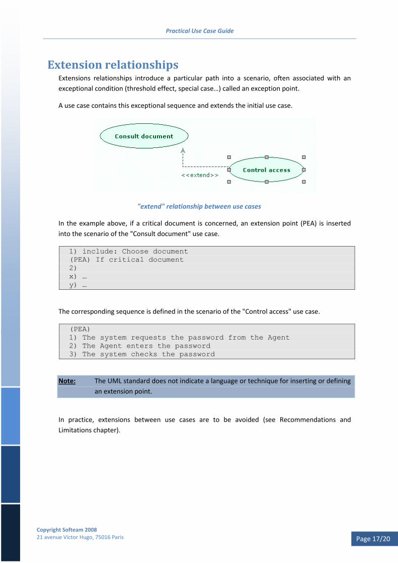
Extension relationships Extensions relationships introduce a particular path into a scenario, often associated with an
exceptional condition (threshold effect, special case…) called an exception point.
A use case contains this exceptional sequence and extends the initial use case.
"extend" relationship between use cases
In the example above, if a critical document is concerned, an extension point (PEA) is inserted
into the scenario of the "Consult document" use case.
1) include: Choose document
(PEA) If critical document
2)
x) …
y) …
The corresponding sequence is defined in the scenario of the "Control access" use case.
(PEA)
1) The system requests the password from the Agent
2) The Agent enters the password
3) The system checks the password
Note: The UML standard does not indicate a language or technique for inserting or defining
an extension point.
In practice, extensions between use cases are to be avoided (see Recommendations and
Limitations chapter).

Practical Use Case Guide
Copyright Softeam 2008 21 avenue Victor Hugo, 75016 Paris
Page 18/20
Inheritance relationships Inheritance between use cases is represented in the same way as inheritance between classes.
Inheritance can be used to define "sub-use cases".
In practice, inheritance between use cases should be avoided (see Recommendations and
Limitations chapter).
For grouping use cases (by functional category, for example), the Package is used (see Structured
Use Cases chapter).
Practical Use Case Guide
Copyright Softeam 2008 21 avenue Victor Hugo, 75016 Paris
Page 19/20
Recommendations and limitations Avoid the use of extension relationships and inheritance links. Their semantics are not sufficiently
rigourous, and the absence of a standard language tends to increase the risk of confusion.
Extensions can be represented in most cases simply through links in scenarios.
“I strongly suggest that you ignore them (extend and inheritance). I’ve seen too many situations in
which teams can get terribly hung up on when to use different use case relationships, and such
energy is wasted.” UML Distilled third edition, Martin Fowler, Addison-Wesley.
Inclusion relationships can be used where there is real factorization. However, this type of use
must remain occasional and must bring added value.
Furthermore, the use of these relationships tends to clutter diagrams with the introduction of
"false use cases", which do not respect the properties previously presented.
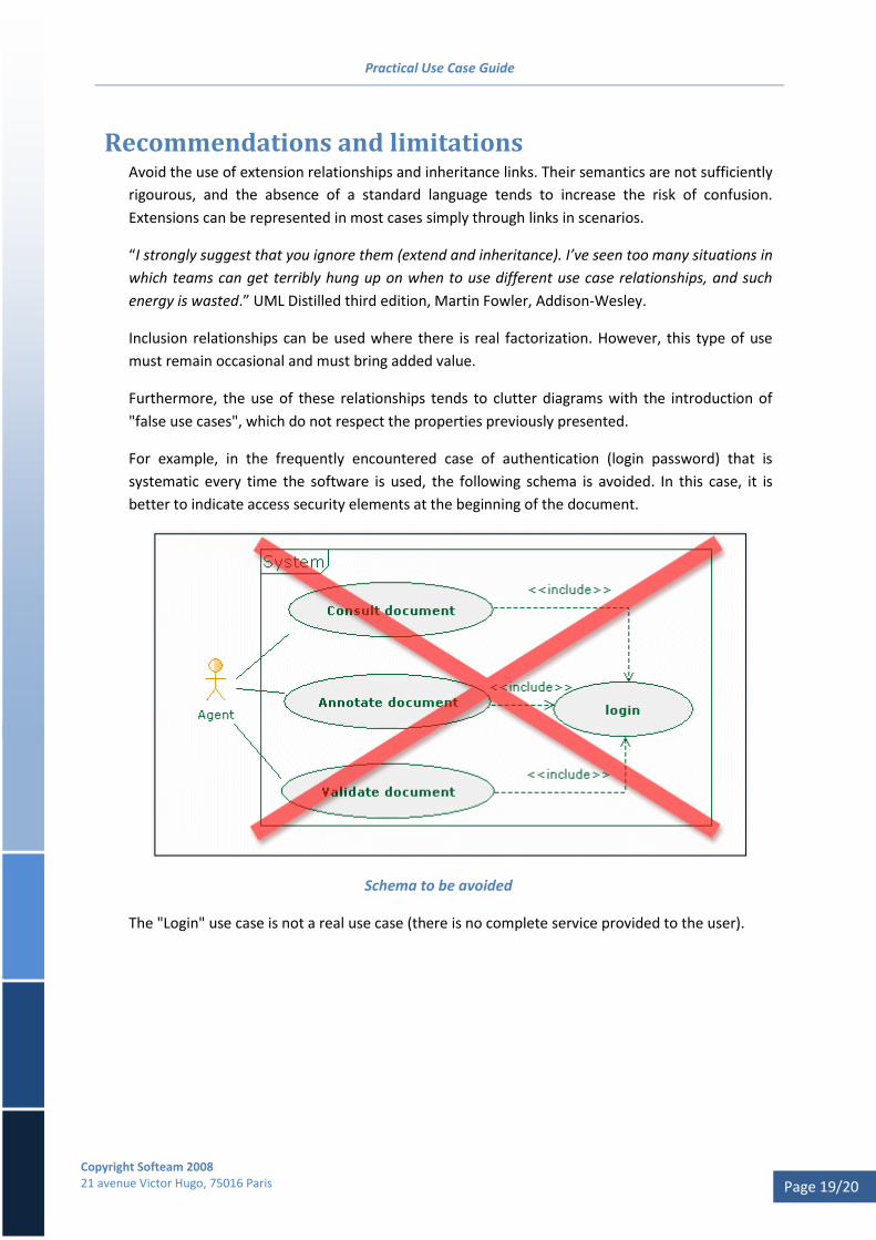
For example, in the frequently encountered case of authentication (login password) that is
systematic every time the software is used, the following schema is avoided. In this case, it is
better to indicate access security elements at the beginning of the document.
Schema to be avoided
The "Login" use case is not a real use case (there is no complete service provided to the user).
Practical Use Case Guide
Copyright Softeam 2008 21 avenue Victor Hugo, 75016 Paris
Page 20/20
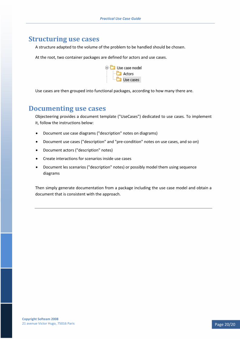
Structuring use cases A structure adapted to the volume of the problem to be handled should be chosen.
At the root, two container packages are defined for actors and use cases.
Use cases are then grouped into functional packages, according to how many there are.
Documenting use cases Objecteering provides a document template ("UseCases") dedicated to use cases. To implement
it, follow the instructions below:
Document use case diagrams ("description" notes on diagrams)
Document use cases ("description" and "pre-condition" notes on use cases, and so on)
Document actors ("description" notes)
Create interactions for scenarios inside use cases
Document les scenarios ("description" notes) or possibly model them using sequence
diagrams
Then simply generate documentation from a package including the use case model and obtain a
document that is consistent with the approach.