
practical Tcp/ip And Ethernet Networking For Industry · Presents Practical TCP/IP and Ethernet...
32
Presents Practical TCP/IP and Ethernet Networking for Industry Revision 5 Website: www.idc-online.com E-mail: [email protected]
Transcript of practical Tcp/ip And Ethernet Networking For Industry · Presents Practical TCP/IP and Ethernet...
Presents
Practical TCP/IP and Ethernet
Networking for Industry
Revision 5
Website: www.idc-online.com E-mail: [email protected]

Copyright All rights to this publication, associated software and workshop are reserved. No part of this publication or associated software may be copied, reproduced, transmitted or stored in any form or by any means (including electronic, mechanical, photocopying, recording or otherwise) without prior written permission of IDC Technologies.
Disclaimer Whilst all reasonable care has been taken to ensure that the descriptions, opinions, programs, listings, software and diagrams are accurate and workable, IDC Technologies do not accept any legal responsibility or liability to any person, organization or other entity for any direct loss, consequential loss or damage, however caused, that may be suffered as a result of the use of this publication or the associated workshop and software.
In case of any uncertainty, we recommend that you contact IDC Technologies for clarification or assistance.
Trademarks All terms noted in this publication that are believed to be registered trademarks or trademarks are listed below:
IBM, XT and AT are registered trademarks of International Business Machines Corporation. Microsoft, MS-DOS and Windows are registered trademarks of Microsoft Corporation.
Acknowledgements IDC Technologies expresses its sincere thanks to all those engineers and technicians on our training workshops who freely made available their expertise in preparing this manual.

Who is IDC Technologies? IDC Technologies is a specialist in the field of industrial communications, telecommunications, automation and control and has been providing high quality training for more than six years on an international basis from offices around the world.
IDC consists of an enthusiastic team of professional engineers and support staff who are committed to providing the highest quality in their consulting and training services. The Benefits to you of Technical Training Today The technological world today presents tremendous challenges to engineers, scientists and technicians in keeping up to date and taking advantage of the latest developments in the key technology areas.
• The immediate benefits of attending IDC workshops are: • Gain practical hands-on experience • Enhance your expertise and credibility • Save $$$s for your company • Obtain state of the art knowledge for your company • Learn new approaches to troubleshooting • Improve your future career prospects The IDC Approach to Training All workshops have been carefully structured to ensure that attendees gain maximum benefits. A combination of carefully designed training software, hardware and well written documentation, together with multimedia techniques ensure that the workshops are presented in an interesting, stimulating and logical fashion.
IDC has structured a number of workshops to cover the major areas of technology. These courses are presented by instructors who are experts in their fields, and have been attended by thousands of engineers, technicians and scientists world-wide (over 11,000 in the past two years), who have given excellent reviews. The IDC team of professional engineers is constantly reviewing the courses and talking to industry leaders in these fields, thus keeping the workshops topical and up to date.

Technical Training Workshops IDC is continually developing high quality state of the art workshops aimed at assisting engineers, technicians and scientists. Current workshops include:
Instrumentation & Control • Practical Automation and Process Control using PLC’s • Practical Data Acquisition using Personal Computers and Standalone
Systems • Practical On-line Analytical Instrumentation for Engineers and Technicians • Practical Flow Measurement for Engineers and Technicians • Practical Intrinsic Safety for Engineers and Technicians • Practical Safety Instrumentation and Shut-down Systems for Industry • Practical Process Control for Engineers and Technicians • Practical Programming for Industrial Control – using (IEC 1131-3;OPC) • Practical SCADA Systems for Industry • Practical Boiler Control and Instrumentation for Engineers and Technicians • Practical Process Instrumentation for Engineers and Technicians • Practical Motion Control for Engineers and Technicians • Practical Communications, SCADA & PLC’s for Managers Communications • Practical Data Communications for Engineers and Technicians • Practical Essentials of SNMP Network Management • Practical Field Bus and Device Networks for Engineers and Technicians • Practical Industrial Communication Protocols • Practical Fibre Optics for Engineers and Technicians • Practical Industrial Networking for Engineers and Technicians • Practical TCP/IP & Ethernet Networking for Industry • Practical Telecommunications for Engineers and Technicians • Practical Radio & Telemetry Systems for Industry • Practical Local Area Networks for Engineers and Technicians • Practical Mobile Radio Systems for Industry

Electrical • Practical Power Systems Protection for Engineers and Technicians • Practical High Voltage Safety Operating Procedures for Engineers &
Technicians • Practical Solutions to Power Quality Problems for Engineers and
Technicians • Practical Communications and Automation for Electrical Networks • Practical Power Distribution • Practical Variable Speed Drives for Instrumentation and Control Systems Project & Financial Management • Practical Project Management for Engineers and Technicians • Practical Financial Management and Project Investment Analysis • How to Manage Consultants Mechanical Engineering • Practical Boiler Plant Operation and Management for Engineers and
Technicians • Practical Centrifugal Pumps – Efficient use for Safety & Reliability Electronics • Practical Digital Signal Processing Systems for Engineers and Technicians • Practical Industrial Electronics Workshop • Practical Image Processing and Applications • Practical EMC and EMI Control for Engineers and Technicians Information Technology • Personal Computer & Network Security (Protect from Hackers, Crackers &
Viruses) • Practical Guide to MCSE Certification • Practical Application Development for Web Based SCADA
Comprehensive Training Materials Workshop Documentation All IDC workshops are fully documented with complete reference materials including comprehensive manuals and practical reference guides. Software
Relevant software is supplied with most workshops. The software consists of demonstration programs which illustrate the basic theory as well as the more difficult concepts of the workshop. Hands-On Approach to Training
The IDC engineers have developed the workshops based on the practical consulting expertise that has been built up over the years in various specialist areas. The objective of training today is to gain knowledge and experience in the latest developments in technology through cost effective methods. The investment in training made by companies and individuals is growing each year as the need to keep topical and up to date in the industry which they are operating is recognized. As a result, the IDC instructors place particular emphasis on the practical hands-on aspect of the workshops presented. On-Site Workshops
In addition to the quality of workshops which IDC presents on a world-wide basis, all IDC courses are also available for on-site (in-house) presentation at our clients’ premises. On-site training is a cost effective method of training for companies with many delegates to train in a particular area. Organizations can save valuable training $$$’s by holding courses on-site, where costs are significantly less. Other benefits are IDC’s ability to focus on particular systems and equipment so that attendees obtain only the greatest benefits from the training.
All on-site workshops are tailored to meet with clients training requirements and courses can be presented at beginners, intermediate or advanced levels based on the knowledge and experience of delegates in attendance. Specific areas of interest to the client can also be covered in more detail. Our external workshops are planned well in advance and you should contact us as early as possible if you require on-site/customized training. While we will always endeavor to meet your timetable preferences, two to three month’s notice is preferable in order to successfully fulfil your requirements. Please don’t hesitate to contact us if you would like to discuss your training needs.

Customized Training
In addition to standard on-site training, IDC specializes in customized courses to meet client training specifications. IDC has the necessary engineering and training expertise and resources to work closely with clients in preparing and presenting specialized courses.
These courses may comprise a combination of all IDC courses along with additional topics and subjects that are required. The benefits to companies in using training are reflected in the increased efficiency of their operations and equipment. Training Contracts
IDC also specializes in establishing training contracts with companies who require ongoing training for their employees. These contracts can be established over a given period of time and special fees are negotiated with clients based on their requirements. Where possible, IDC will also adapt courses to satisfy your training budget.
References from various international companies to whom IDC is contracted to provide on-going technical training are available on request.
Some of the thousands of Companies worldwide that have supported and benefited from IDC workshops are: Alcoa, Allen-Bradley, Altona Petrochemical, Aluminum Company of America, AMC Mineral Sands, Amgen, Arco Oil and Gas, Argyle Diamond Mine, Associated Pulp and Paper Mill, Bailey Controls, Bechtel, BHP Engineering, Caltex Refining, Canon, Chevron, Coca-Cola, Colgate-Palmolive, Conoco Inc, Dow Chemical, ESKOM, Exxon, Ford, Gillette Company, Honda, Honeywell, Kodak, Lever Brothers, McDonnell Douglas, Mobil, Modicon, Monsanto, Motorola, Nabisco, NASA, National Instruments, National Semi-Conductor, Omron Electric, Pacific Power, Pirelli Cables, Proctor and Gamble, Robert Bosch Corp, Siemens, Smith Kline Beecham, Square D, Texaco, Varian, Warner Lambert, Woodside Offshore Petroleum, Zener Electric


Preface One of the great protocols that has been inherited from the Internet is TCP/IP and this is being used as the open standard today for all network and communications systems. The reasons for this popularity are not hard to find. TCP/IP and Ethernet are truly open standards available to competing manufacturers and provide the user with a common standard for a variety of products from different vendors. In addition, the cost of TCP/IP and Ethernet is relatively low. Initially TCP/IP was used extensively in military applications and the purely commercial world such as banking, finance, and general business. But of great interest has been the strong movement to universal usage by the hitherto disinterested industrial and manufacturing spheres of activity who has traditionally used their own proprietary protocols and standards. These proprietary standards have been almost entirely replaced by the usage of the TCP/IP suite of protocols.
This is a hands-on book that has been structured to cover the main areas of TCP/IP and Ethernet in detail, while covering the practical implementation of TCP/IP in computer and industrial applications. Troubleshooting and maintenance of TCP/IP networks and communications systems in industrial environment will also be covered.
After reading this manual we would hope you would be able to:
• Understand the fundamentals of the TCP/IP suite of protocols • Gain a practical understanding of the application of TCP/IP • Learn how to construct a robust Local Area Network (LAN) • Learn the basic skills in troubleshooting TCP/IP and LANs • Apply the TCP/IP suite of protocols to both an office and industrial
environment
Typical people who will find this book useful include:
• Network technicians • Data communications managers • Communication specialists • IT support managers and personnel • Network planners • Programmers • Design engineers • Electrical engineers • Instrumentation and control engineers • System integrators • System analysts • Designers • IT and MIS managers • Network support staff • Systems engineers
You should have a modicum of computer knowledge and know how to use the Microsoft Windows
operating system in order to derive maximum benefit from this book.

xviii Preface
The structure of the book is as follows. Chapter 1: Overview. This chapter gives a brief overview of what is covered in the book with an outline of the essentials of communications systems. Chapter 2: Networking fundamentals. An overview of network communication, types of networks, the OSI model, network topologies and media access methods. Chapter 3: Half-duplex (CSMA/CD) Ethernet networks. A description of the operation and performance of the older 10 Mbps Ethernet networks commencing with the basic principles. Chapter 4: Fast and Gigabit Ethernet Systems. A minimum speed of 100 Mbps is becoming de rigeur on most Ethernet networks and this chapter examines the design and installation issues for Fast Ethernet and Gigabit Ethernet systems, which go well beyond the traditional 10 Mbps speed of operation. Chapter 5: Introduction to TCP/IP. A brief review of the origins of TCP/IP to lay the foundation for the following chapters. Chapter 6: Internet layer protocols. This chapter fleshes out the Internet Protocol (both IPv4 and IPv6) - perhaps the workhorses of the TCP/IP suite of protocols - and also examines the operation of ARP, RARP and ICMP. Chapter 7: Host-to-Host (Transport) layer protocols. The TCP (Transmission Control Protocol) and UDP (User Datagram Protocol) are both covered in this chapter. Chapter 8: Application layer protocols. A thorough coverage of the most important Application layer protocols such as FTP, TFTP, TELNET, DNS, WINS, SNMP, SMTP, POP, BOOTP and DHCP. Chapter 9: TCP/IP utilities. A coverage focusing on the practical application of the main utilities such as PING, ARP, NETSTAT NBTSTAT, IPCONFIG, WINIPCFG, TRACERT, ROUTE and the HOSTS file. Chapter 10: LAN system components. A discussion on the key components for interconnecting networks such as repeaters, bridges, switches and routers. Chapter 11: VLANs. An overview of Virtual LANS; what they are used for, how they are set up, and how they operate. Chapter 12: VPNs. This chapter discusses the rationale behind VPN deployment and takes a look at the various protocols and security mechanisms employed. Chapter 13: The Internet for communications. The various TCP/IP protocols used for VoIP (Voice over IP) are discussed here, as well as the H.323 protocols and terminology. Chapter 14: Security considerations. The security problem and methods of controlling access to a network will be examined in this chapter. This is a growing area of importance due to the proliferation attacks on computer networks by external parties.

Preface xix
Chapter 15: Process automation. The legacy architectures and the factory of the future will be examined here together with an outline of the key elements of the modern Ethernet and TCP/IP architecture. Chapter 16: Troubleshooting Ethernet. Various troubleshooting techniques as well as the required equipment used will be described here, focusing on the medium as well as layers 1 and 2 of the OSI model. Chapter 17: Troubleshooting TCP/IP. This chapter covers the troubleshooting and maintenance of a TCP/IP network, focusing on layers 3 and 4 of the OSI model and dealing with the use of protocol analyzers. Chapter 18: Satellites and TCP/IP. An overview of satellites and the problems/solutions associated with running TCP/IP over a satellite link.

xx Preface
Contents Preface vi 1 Introduction to Communications 1
1.1 Data communications 1 1.2 Transmitters, receivers and communication channels 2 1.3 Types of communication channels 4 1.4 Communications channel properties 5 1.5 Data transmission modes 8 1.6 Encoding methods 12 1.7 Error detection 14
2 Networking Fundamentals 17 2.1 Overview 17 2.2 Network communication 18 2.3 Types of network 21 2.4 The OSI model 23 2.5 Interoperability and internetworking 31 2.6 Protocols and protocol standards 32 2.7 IEEE/ISO standards 33 2.8 Network topologies 35 2.9 Bus topology 36 2.10 Star topology 37 2.11 Ring topology 38 2.12 Other topologies 39 2.13 Media access control methods 42
3 10 Mbps Half-duplex (CSMA/CD) Ethernet 45 3.1 The origins of Ethernet 45 3.2 Physical layer implementations 46 3.3 Signaling methods 50 3.4 Medium access control 51 3.5 Frame transmission 51 3.6 Frame reception 52 3.7 Collisions 52 3.8 Frame format 54 3.9 Reducing collisions 56 3.10 Half-duplex Ethernet design rules 56
4 Fast and Gigabit Ethernet systems 59 4.1 Achieving higher speed 59 4.2 100Base-T 60

4.3 Fast Ethernet design considerations 63 4.4 Gigabit Ethernet 65 4.5 Gigabit Ethernet design considerations 70
5 Introduction to TCP/IP 73 5.1 The origins of TCP/IP 73 5.2 The ARPA model vs the OSI model 74 5.3 The TCP/IP protocol suite vs the ARPA model 75
6 Internet Layer Protocols 79 6.1 Overview 79 6.2 IPv4 80 6.3 IPv6/IPng 95 6.4 ARP 103 6.5 RARP 107 6.6 ICMP 108 6.7 Routing protocols 115 6.8 IGPs 118 6.9 EGPs 121
7 Host- to-host (transport) Layer Protocols 123 7.1 TCP 124 7.2 UDP 132
8 Application Layer Protocols 135 8.1 introduction 135 8.2 FTP 136 8.3 TFTP 139 8.4 TELNET 142 8.5 DNS 146 8.6 WINS 150 8.7 SNMP 152 8.8 SMTP 155 8.9 POP 156 8.10 BOOTP 157 8.11 DHCP 159
9 TCP/IP Utilities 163 9.1 Introduction 163 9.2 PING 163 9.3 ARP 167 9.4 NETSTAT 168 9.5 NBTSTAT 169 9.6 IPCONFIG 170
9.7 WINIPCFG/ WNITPCFG 171 9.8 TRACE RouTe 172 9.9 ROUTE 175 9.10 The HOSTS file 177
10 LAN System Components 179
10.1 Introduction 179 10.2 Repeaters 180 10.3 Media converters 181 10.4 Bridges 182 10.5 Hubs 184 10.6 Switches 187 10.7 Routers 192 10.8 Gateways 194 10.9 Print servers 194 10.10 Terminal servers 194 10.11 Thin servers 195 10.12 Remote access servers 195 10.13 Network time servers 196
11 Virtual LANs (VLANs) 197 11.1 The need for VLAN technology 197 11.2 Benefits of VLAN 200 11.3 VLAN restrictions 201 11.4 Basic operation of a VLAN 201 11.5 VLAN implementation 202 11.6 Interconnection methods 206 11.7 Filtering table 208 11.8 Tagging 209
12 Virtual Private Networks (VPNs) 211 12.1 Introduction 211 12.2 What is a VPN? 213 12.3 Types of VPN 213 12.4 Requirements for designing a VPN 214 12.5 Defining policies 215 12.6 Functional requirements 216 12.7 Security 223
13 The Internet for Communication 235 13.1 Introduction 235 13.2 Protocols 236 13.3 Hardware 245 13.4 Implementation considerations: QoS 255

14 Security Considerations 257 14.1 The security problem 257 14.2 Authentication 259 14.3 Routers 260 14.4 Firewalls 261 14.5 Intrusion Detection Systems (IDSs) 268 14.6 Security management 268 14.7 The Public Key Infrastructure (PKI) 271
15 Process Automation 277 15.1 Background 277 15.2 Legacy automation architectures 277 15.3 The ‘factory of the future’ 280 15.4 Modbus/ TCP 286 15.5 Ethernet/IP (Ethernet/ Industrial Protocol) 290
16 Troubleshooting Ethernet 293 16.1 introduction 293 16.2 Common problems and faults 293 16.3 Tools of the trade 293 16.4 Problems and solutions 295 16.5 Troubleshooting switched networks 305 16.6 Troubleshooting fast Ethernet 305 16.7 Troubleshooting Gigabit Ethernet 305
17 TCP/IP Troubleshooting 307 17.1 Introduction 307 17.2 Tools of the trade 307 17.3 Typical network layer problems 307 17.4 Transport layer problems 310
18 Satellites and TCP/ IP 311 18.1 introduction 311 18.2 Overview of satellite communications 311 18.3 Advantages of satellite networks 314 18.4 Applications of satellite systems 315 18.5 Weaknesses of TCP/IP in satellite usage 316 18.6 Methods of optimizing TCP/IP over satellite channels 317
Appendices 321
Appendix A -Glossary 321 Appendix B - Port number allocation 339 Practical Exercises 341 Practical Exercises - Solutions 359

1
Introduction to Communications
Learning objectives When you have completed study of this chapter you should:
• Understand the main elements of the data communication process • Understand the difference between analog and digital transmission • Explain how data transfer is affected by attenuation, bandwidth and noise in
the channel • Comprehend the importance of synchronization of digital data systems • Describe the basic synchronization concepts used with asynchronous and
synchronous systems • Explain the following types of encoding:
• Manchester • RZ • NRZ • MLT-3 • 4B/5B • Describe the basic error detection principles.
1.1 Data communications Communications systems transfer messages from one location to another. The information component of a message is usually known as data (derived from the Latin word for items of information). All data is made up of unique code symbols or other entities on which the sender and receiver of the messages have agreed. For example, binary data is represented by two states viz. ‘0’ and ‘1’. These are referred to as binary digits or ‘bits’ and are represented inside computers by the level of the electrical signals within storage elements; a high level could represent a ‘1’, and a low-level could
2 Practical TCP/IP and Ethernet Networking for Industry
represent a ‘0’. Alternatively, the data may be represented by the presence or absence of light in an optical fiber cable.
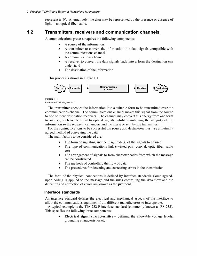
1.2 Transmitters, receivers and communication channels A communications process requires the following components:
• A source of the information • A transmitter to convert the information into data signals compatible with
the communications channel • A communications channel • A receiver to convert the data signals back into a form the destination can
understand • The destination of the information
This process is shown in Figure 1.1.
Figure 1.1 Communications process
The transmitter encodes the information into a suitable form to be transmitted over the communications channel. The communications channel moves this signal from the source to one or more destination receivers. The channel may convert this energy from one form to another, such as electrical to optical signals, whilst maintaining the integrity of the information so the recipient can understand the message sent by the transmitter.
For the communications to be successful the source and destination must use a mutually agreed method of conveying the data.
The main factors to be considered are: • The form of signaling and the magnitude(s) of the signals to be used • The type of communications link (twisted pair, coaxial, optic fiber, radio
etc) • The arrangement of signals to form character codes from which the message
can be constructed • The methods of controlling the flow of data • The procedures for detecting and correcting errors in the transmission
The form of the physical connections is defined by interface standards. Some agreed-
upon coding is applied to the message and the rules controlling the data flow and the detection and correction of errors are known as the protocol.
Interface standards An interface standard defines the electrical and mechanical aspects of the interface to allow the communications equipment from different manufacturers to interoperate.
A typical example is the TIA-232-F interface standard (commonly known as RS-232). This specifies the following three components:
• Electrical signal characteristics – defining the allowable voltage levels, grounding characteristics etc

Introduction to Communications 3
• Mechanical characteristics – defining the connector arrangements and pin assignments
• Functional description of the interchange circuits – defining the function of the various data, timing and control signals used at the interface
It should be emphasized that the interface standard only defines the electrical and
mechanical aspects of the interface between devices and does not define how data is transferred between them.
Coding A wide variety of codes have been used for communications purposes. Early telegraph communications used Morse code with human operators as transmitter and receiver. The Baudot code introduced a constant 5-bit code length for use with mechanical telegraph transmitters and receivers. The commonly used codes for data communications today are the Extended Binary Coded Decimal Interchange Code (EBCIDIC) and the American Standard Code for Information Interchange (ASCII).
Protocols A protocol is essential for defining the common message format and procedures for transferring data between all devices on the network. It includes the following important features:
• Initialization: Initializes the protocol parameters and commences the data transmission
• Framing and synchronization: Defines the start and end of the frame and how the receiver can synchronize to the data stream
• Flow control: Ensures that the receiver is able to advise the transmitter to regulate the data flow and ensure no data is lost.
• Line control: Used with half-duplex links to reverse the roles of transmitter and receiver and begin transmission in the other direction.
• Error control: Provides techniques to check the accuracy of the received data to identify transmission errors. These include block redundancy checks and cyclic redundancy checks
• Time out control: Procedures for transmitters to retry or abort transmission when acknowledgments are not received within agreed time limits
Some commonly used communications protocols • X/ Y/ Z modem and Kermit for asynchronous file transmission • Binary Synchronous Protocol (BSC), Synchronous Data Link Control
(SDLC) or High-Level Data Link Control (HDLC) for synchronous transmissions
• Industrial protocols such as Modbus and DNP3
4 Practical TCP/IP and Ethernet Networking for Industry
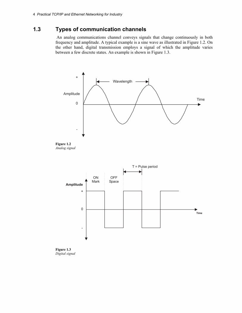
1.3 Types of communication channels An analog communications channel conveys signals that change continuously in both frequency and amplitude. A typical example is a sine wave as illustrated in Figure 1.2. On the other hand, digital transmission employs a signal of which the amplitude varies between a few discrete states. An example is shown in Figure 1.3.
Figure 1.2 Analog signal
Figure 1.3 Digital signal

Introduction to Communications 5
1.4 Communications channel properties
Signal attenuation As the signal travels along a communications channel its amplitude decreases as the physical medium resists the flow of the signal energy. This effect is known as signal attenuation. With electrical signaling some materials such as copper are very efficient conductors of electrical energy. However, all conductors contain impurities that resist the movement of the electrons that constitute the electric current. The resistance of the conductors causes some of the electrical energy of the signal to be converted to heat as the signal progresses along the cable resulting in a continuous decrease in the electrical signal. The signal attenuation is measured in terms of signal loss per unit length of the cable, typically dB/km. To allow for attenuation, a limit is set for the maximum length of the communications channel. This is to ensure that the attenuated signal arriving at the receiver is of sufficient amplitude to be reliably detected and correctly interpreted. If the channel is longer than this maximum specified length, repeaters must be used at intervals along the channel to restore the signal to acceptable levels.
Figure 1.4 Signal repeaters
Signal attenuation increases as the frequency increases. This causes distortion to practical signals containing a range of frequencies. This problem can be overcome by the use of amplifiers that amplify the higher frequencies by greater amounts.
Channel bandwidth The quantity of information a channel can convey over a given period is determined by its ability to handle the rate of change of the signal, i.e. the signal frequency. The bandwidth of an analog channel is the difference between the highest and lowest frequencies that can be reliably transmitted over the channel. These frequencies are often defined as those at which the signal at the receiving end has fallen to half the power relative to the mid-band frequencies (referred to as the -3 dB points), in which case the bandwidth is known as the -3 dB bandwidth.

6 Practical TCP/IP and Ethernet Networking for Industry
Figure 1.5 Channel bandwidth
Digital signals are made up of a large number of frequency components, but only those within the bandwidth of the channel will be able to be received. It follows that the larger the bandwidth of the channel, the higher the data transfer rate can be and more high frequency components of the digital signal can be transported, and so a more accurate reproduction of the transmitted signal can be received.
Figure 1.6 Effect of channel bandwidth on digital signal

Introduction to Communications 7
The maximum data transfer rate (C) of the transmission channel can be determined from its bandwidth, by use of the following formula derived by Shannon.
C= 2B log2 M bps Where: B = bandwidth in hertz and M levels are used for each signaling element. In the special case where only two levels, ‘ON’ and ‘OFF’ are used (binary), M = 2 and
C = 2 B. For example, the maximum data transfer rate for a PSTN channel with 3200 hertz bandwidth carrying a binary signal would be 2 × 3200 = 6400 bps. The achievable data transfer rate would then be reduced by half because of the Nyquist rate. It is further reduced in practical situations because of the presence of noise on the channel to approximately 2400 bps unless some modulation system is used.
Noise As the signals pass through a communications channel the atomic particles and molecules in the transmission medium vibrate and emit random electromagnetic signals as noise. The strength of the transmitted signal is normally large relative to the noise signal. However, as the signal travels through the channel and is attenuated, its level can approach that of the noise. When the wanted signal is not significantly higher than the background noise, the receiver cannot separate the data from the noise and communication errors occur.
An important parameter of the channel is the ratio of the power of the received signal (S) to the power of the noise signal (N). The ratio S/N is called the Signal to Noise ratio, normally expressed in decibels (dB).
S/N = 10 log10 (S/N) dB Where signal and noise levels are expressed in watts, or S/N = 20 log10 (S/N) dB Where signal and noise levels are expressed in volts A high signal to noise ratio means that the wanted signal power is high compared to the
noise level, resulting in good quality signal reception The theoretical maximum data transfer rate for a practical channel can be calculated
using the Shannon-Hartley law, which states that: C = B log2 (1+S/N) bps Where: C = data rate in bps B = bandwidth of the channel in hertz S = signal power in watts and

8 Practical TCP/IP and Ethernet Networking for Industry
N = noise power in watts It can be seen from this formula that increasing the bandwidth or increasing the S/N
ratio will allow increases to the data rate, and that a relatively small increase in bandwidth is equivalent to a much greater increase in S/N ratio.
Digital transmission channels make use of higher bandwidths and digital repeaters or regenerators to regenerate the signals at regular intervals and maintain acceptable signal to noise ratios. The degraded signals received at the regenerator are detected, then re-timed and retransmitted as nearly perfect replicas of the original digital signals, as shown in Figure 1.7. Provided the signal to noise ratios is maintained in each link, there is no accumulated noise on the signal, even when transmitted over thousands of kilometers.
Figure 1.7 Digital link
1.5 Data transmission modes
Direction of signal flow
Simplex A simplex channel is unidirectional and allows data to flow in one direction only, as shown in Figure 1.8. Public radio broadcasting is an example of a simplex transmission. The radio station transmits the broadcast program, but does not receive any signals back from the receiver(s).
Figure 1.8 Simplex transmission
Introduction to Communications 9
This has limited use for data transfer purposes, as we invariably require the flow of data in both directions to control the transfer process, acknowledge data etc.
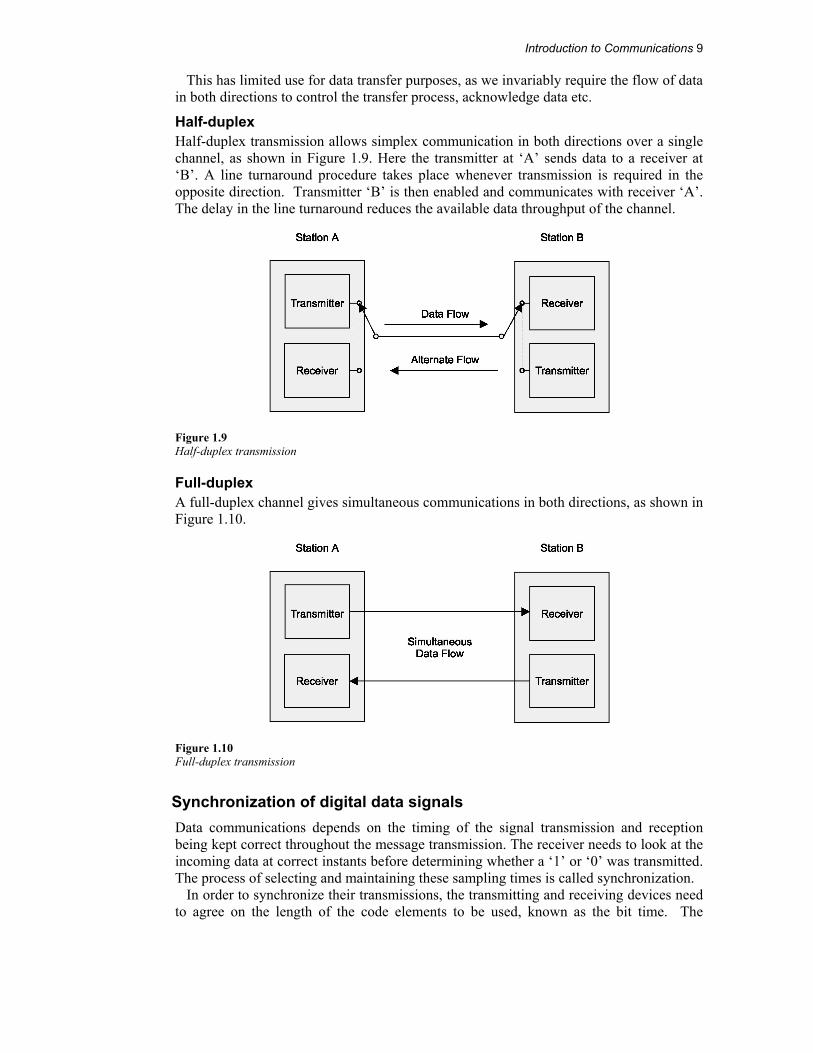
Half-duplex Half-duplex transmission allows simplex communication in both directions over a single channel, as shown in Figure 1.9. Here the transmitter at ‘A’ sends data to a receiver at ‘B’. A line turnaround procedure takes place whenever transmission is required in the opposite direction. Transmitter ‘B’ is then enabled and communicates with receiver ‘A’. The delay in the line turnaround reduces the available data throughput of the channel.
Figure 1.9 Half-duplex transmission
Full-duplex A full-duplex channel gives simultaneous communications in both directions, as shown in Figure 1.10.
Figure 1.10 Full-duplex transmission
Synchronization of digital data signals Data communications depends on the timing of the signal transmission and reception being kept correct throughout the message transmission. The receiver needs to look at the incoming data at correct instants before determining whether a ‘1’ or ‘0’ was transmitted. The process of selecting and maintaining these sampling times is called synchronization.
In order to synchronize their transmissions, the transmitting and receiving devices need to agree on the length of the code elements to be used, known as the bit time. The
10 Practical TCP/IP and Ethernet Networking for Industry
receiver also needs to synchronize its clock with that of the sender in order to determine the right times at which to sample the data bits in the message. A device at the receiving end of a digital channel can synchronize itself using either asynchronous or synchronous means as outlined below.
Asynchronous transmission Here the transmitter and receiver operate independently, and the receiver synchronizes its clock with that of the transmitter (only) at the start of each message frame. Transmissions are typically around one byte in length, but can also be longer. Often (but not necessarily) there is no fixed relationship between one message frame and the next, such as a computer keyboard input with potentially long random pauses between keystrokes.
IDLE IDLE IDLE IDLE
Variable delaysbetween frames
Frame 1 Frame 2 Frame 3
Figure 1.11 Asynchronous data transmission
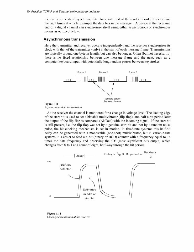
At the receiver the channel is monitored for a change in voltage level. The leading edge of the start bit is used to set a bistable multivibrator (flip-flop), and half a bit period later the output of the flip-flop is compared (ANDed) with the incoming signal. If the start bit is still present, i.e. the flip-flop was set by a genuine start bit and not by a random noise pulse, the bit clocking mechanism is set in motion. In fixed-rate systems this half-bit delay can be generated with a monostable (one-shot) multivibrator, but in variable-rate systems it is easier to feed a 4-bit (binary or BCD) counter with a frequency equal to 16 times the data frequency and observing the ‘D’ (most significant bit) output, which changes from 0 to 1 at a count of eight, half-way through the bit period.
-ve
+veStart bit
detected
Estimated
middle of
start bit
Delay Delay = 12/ X Bit period = Baudrate
2
Figure 1.12 Clock synchronization at the receiver

Introduction to Communications 11
The input signal is fed into a serial-in parallel-out shift register. The data bits are then
captured by clocking the shift register at the data rate, in the middle of each bit. For an eight-bit serial transmission (data plus parity), this sampling is repeated for each of the eight data bits and a final sample is made during the ninth time interval to identify the stop bit and to confirm that the synchronization has been maintained to the end of the frame. Figure 1.13 illustrates the asynchronous data reception process.
Data Bit
Received Data
1 2 3 4 5 6 7 8
1 0 1 1 0 1 0 1
IDLESTATE
RETURN TOIDLE STATE
StartBit
StopBit
BitPeriod
Centre ofStart Bit
Receiver Sampling Instants
ASYNCHRONOUS DATA RECEPTION
DATA FLOW
SPACE(0)
MARK(1)
Bit
1 2 3 4 5 6 7 8
Figure 1.13 Asynchronous data reception (clock too slow)
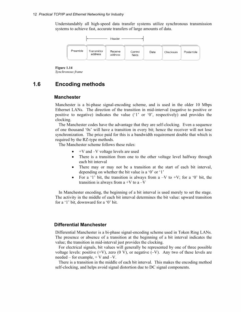
Synchronous transmission The receiver here is initially synchronized with the transmitter, and then maintains this synchronization throughout the continuous transmission of multiple bytes. This is achieved by special data coding schemes, such as Manchester, which ensure that the transmitted clock is encoded into the transmitted data stream. This enables the synchronization to be maintained at the receiver right to the last bit of the message, and thus allows larger frames of data (up to several thousand bytes) to be efficiently transferred at high data rates. The synchronous system packs many bytes together and sends them as a continuous stream, called a frame. Each frame consists of a header, data field and checksum. Clock synchronization is provided by a predefined sequence of bits called a preamble. In some cases the preamble is terminated with a ‘Start of Frame Delimiter’ or SFD. Some systems may append a post-amble if the receiver is not otherwise able to detect the end of the message. An example of a synchronous frame is shown in Figure 1.14.
12 Practical TCP/IP and Ethernet Networking for Industry
Understandably all high-speed data transfer systems utilize synchronous transmission systems to achieve fast, accurate transfers of large amounts of data.
Figure 1.14 Synchronous frame
1.6 Encoding methods
Manchester Manchester is a bi-phase signal-encoding scheme, and is used in the older 10 Mbps Ethernet LANs. The direction of the transition in mid-interval (negative to positive or positive to negative) indicates the value (‘1’ or ‘0’, respectively) and provides the clocking.
The Manchester codes have the advantage that they are self-clocking. Even a sequence of one thousand ‘0s’ will have a transition in every bit; hence the receiver will not lose synchronization. The price paid for this is a bandwidth requirement double that which is required by the RZ-type methods.
The Manchester scheme follows these rules: • +V and –V voltage levels are used • There is a transition from one to the other voltage level halfway through
each bit interval • There may or may not be a transition at the start of each bit interval,
depending on whether the bit value is a ‘0’ or ‘1’ • For a ‘1’ bit, the transition is always from a –V to +V; for a ‘0’ bit, the
transition is always from a +V to a –V In Manchester encoding, the beginning of a bit interval is used merely to set the stage.
The activity in the middle of each bit interval determines the bit value: upward transition for a ‘1’ bit, downward for a ‘0’ bit.
Differential Manchester Differential Manchester is a bi-phase signal-encoding scheme used in Token Ring LANs. The presence or absence of a transition at the beginning of a bit interval indicates the value; the transition in mid-interval just provides the clocking.
For electrical signals, bit values will generally be represented by one of three possible voltage levels: positive (+V), zero (0 V), or negative (–V). Any two of these levels are needed – for example, + V and –V.
There is a transition in the middle of each bit interval. This makes the encoding method self-clocking, and helps avoid signal distortion due to DC signal components.

Introduction to Communications 13
For one of the possible bit values but not the other, there will be a transition at the start of any given bit interval. For example, in a particular implementation, there may be a signal transition for a ‘1’ bit.
In differential Manchester encoding, the presence or absence of a transition at the beginning of the bit interval determines the bit value. In effect, ‘1’ bits produce vertical signal patterns; ‘0’ bits produce horizontal patterns. The transition in the middle of the interval is just for timing.
RZ (return to zero) The RZ-type codes consume only half the bandwidth taken up by the Manchester codes. However, they are not self-clocking since a sequence of a thousand ‘0s’ will result in no movement on the transmission medium at all.
RZ is a bipolar signal-encoding scheme that uses transition coding to return the signal to a zero voltage during part of each bit interval. It is self-clocking.
In the differential version, the defining voltage (the voltage associated with the first half of the bit interval) changes for each ‘1’ bit, and remains unchanged for each ‘0’ bit.
In the non-differential version, the defining voltage changes only when the bit value changes, so that the same defining voltages are always associated with ‘0’ and ‘1’. For example, +5 volts may define a ‘1’, and –5 volts may define a ‘0’.
NRZ (non-return to zero) NRZ is a bipolar encoding scheme. In the non-differential version it associates, for example, +5 V with ‘1’ and –5 V with ‘0’.
In the differential version, it changes voltages between bit intervals for ‘1’ values but not for ‘0’ values. This means that the encoding changes during a transmission. For example, ‘0’ may be a positive voltage during one part and a negative voltage during another part, depending on the last occurrence of a ‘1’. The presence or absence of a transition indicates a bit value, not the voltage level.
MLT-3 MLT-3 is a three-level encoding scheme that can also scramble data. This scheme is one proposed for use in FDDI networks. The MLT-3 signal-encoding scheme uses three voltage levels (including a zero level) and changes levels only when a ‘1’ occurs.
It follows these rules: • +V, 0 V, and –V voltage levels are used • The voltage remains the same during an entire bit interval; that is, there are
no transitions in the middle of a bit interval • The voltage level changes in succession; from +V to 0 V to –V to 0 V to
+V, and so on • The voltage level changes only for a ‘1’ bit
MLT-3 is not self-clocking, so that a synchronization sequence is needed to make sure
the sender and receiver are using the same timing.

14 Practical TCP/IP and Ethernet Networking for Industry
4B/5B The Manchester codes, as used for 10 Mbps Ethernet, are self-clocking but consume unnecessary bandwidth (at 10 Mbps it introduces a 20 MHz frequency component on the medium). For this reason it is not possible to use it for 100 Mbps Ethernet, even over Cat5 cable. A solution is to revert back to one of the more bandwidth efficient methods such as NRZ or RZ. The problem with these, however, is that they are not self-clocking and hence the receiver loses synchronization if several zeros are transmitted sequentially. This problem, in turn, is overcome by using the 4B/5B technique.
The 4B/5B technique codes each group of four bits into a five-bit code. For example, the binary pattern 0110 is coded into the five-bit pattern 01110. This code table has been designed in such a way that no combination of data can ever be encoded with more than 3 zeros on a row. This allows the carriage of 100 Mbps data by transmitting at 125 MHz, as opposed to the 200 Mbps required by Manchester encoding.
Table 1.1 4B/5B data coding
1.7 Error detection All practical data communications channels are subject to noise, particularly where equipment is situated in industrial environments with high electrical noise, such as electromagnetic radiation from adjacent equipment or electromagnetic induction from adjacent cables. As a consequence the received data may contain errors. To ensure reliable data communication we need to check the accuracy of each message.
Asynchronous systems often use a single bit checksum, the parity bit, for each message, calculated from the seven or eight data bits in the message. Longer messages require more complex checksum calculations to be effective. For example the Longitudinal Redundancy Check (LRC) calculates an additional byte covering the content of the message (up to 15 bytes) while a two-byte arithmetic checksum can be used for messages up to 50 bytes in length. Most high-speed LANs use a 32-bit Cyclic Redundancy Check (CRC)

Introduction to Communications 15
The CRC method detects errors with very high degree of accuracy in messages of any length and can, for example, detect the presence of a single bit error in a frame containing tens of thousands of bits of data. The CRC treats all the bits of the message block as one binary number that is then divided by a known polynomial. For a 32-bit CRC this is a specific 32-bit number, specially chosen to detect very high percentages of errors, including all error sequences of less than 32 bits. The remainder found after this division process is the CRC. Calculation of the CRC is carried out by the hardware in the transmission interface of LAN adapter cards.

16 Practical TCP/IP and Ethernet Networking for Industry