Practical methodology to evaluate the fatigue life of seam...
7
© Copyright by International OCSCO World Press. All rights reserved. 2011 Research paper 35 VOLUME 49 ISSUE 1 November 2011 of Achievements in Materials and Manufacturing Engineering of Achievements in Materials and Manufacturing Engineering Practical methodology to evaluate the fatigue life of seam welded joints K.C.Goes a , G.F. Batalha b, *, M.V. Pereira c , A.F. Camarao d a PETROBRAS - Petróleo Brasileiro, Av. Republica do Chile 65, Rio de Janeiro, RJ, Brazil b University of Sao Paulo - Escola Politecnica POLI-USP, Av. Prof. Mello Moraes 2231, São Paulo, SP, Brazil c Catholic University of Rio de Janeiro - PUC-RJ, Rua Marquês de Sao Vicente 225, Rio de Janeiro, RJ, Brazil d Meritor do Brasil Sistemas Automotivos Ltda, Av. Joao Batista 825, Osasco, SP, Brazil * Corresponding author: E-mail address: [email protected] Received 11.09.2011; published in revised form 01.11.2011 Properties ABSTRACT Purpose: of this paper is to present a practical and robust methodology developed to evaluate the fatigue life of seam welded joints under combined cyclic loading. Design/methodology/approach: Fatigue analysis was conducted in virtual environment. The finite element stress results from each loading were imported to fatigue code FE-Fatigue and combined to perform the fatigue life prediction using the S x N (stress x life) method. A tube-to-plate specimen was submitted to a combined cyclic loading (bending and torsion) with constant amplitude. The virtual durability analysis result was calibrated based on these laboratory tests and design codes such as BS7608 and Eurocode 3. The feasibility and application of the proposed numerical-experimental methodology and contributions for the technical development are discussed. Major challenges associated with this modelling and improvement proposals are finally presented. Findings: The finite element model was validated due to laboratory results. The analytical stress result presented upper value due to the approach used that considered the fillet weld supported all work. The model presented a good representation of failure and load correlation. Research limitations/implications: The measurement or modelling of the residual stresses resulting from the welding process was not included in this work. However, the thermal and metallurgical effects, such as distortions and residual stresses, were considered indirectly with regard to the corrections performed in the fatigue curves obtained from the investigated samples. Practical implications: Integrating fatigue analysis and finite elements, it is possible to analyse several welded joint configurations in the design phase, providing development time and cost reduction, increasing the project reliability. Originality/value: This methodology will permit, in further studies, the modelling of both stresses, in-service and residual stresses, acting together, which seem like an advantage to engineers and researchers who work in design and evaluation of structural components against fatigue failures. Keywords: Fatigue; Combined loading; Finite element analysis; Welding Reference to this paper should be given in the following way: K.C.Goes, G.F. Batalha, M.V. Pereira, A.F. Camarao, Practical methodology to evaluate the fatigue life of seam welded joints, Journal of Achievements in Materials and Manufacturing Engineering 49/1 (2011) 35-41.
Transcript of Practical methodology to evaluate the fatigue life of seam...
© Copyright by International OCSCO World Press. All rights reserved. 2011 Research paper 35
VOLUME 49
ISSUE 1
November
2011of Achievements in Materialsand Manufacturing Engineeringof Achievements in Materialsand Manufacturing Engineering
Practical methodology to evaluate the fatigue life of seam welded joints
K.C.Goes a, G.F. Batalha b,*, M.V. Pereira c, A.F. Camarao da PETROBRAS - Petróleo Brasileiro, Av. Republica do Chile 65, Rio de Janeiro, RJ, Brazil b University of Sao Paulo - Escola Politecnica POLI-USP, Av. Prof. Mello Moraes 2231, São Paulo, SP, Brazil c Catholic University of Rio de Janeiro - PUC-RJ, Rua Marquês de Sao Vicente 225, Rio de Janeiro, RJ, Brazild Meritor do Brasil Sistemas Automotivos Ltda, Av. Joao Batista 825, Osasco, SP, Brazil* Corresponding author: E-mail address: [email protected]
Received 11.09.2011; published in revised form 01.11.2011
Properties
AbstrAct
Purpose: of this paper is to present a practical and robust methodology developed to evaluate the fatigue life of seam welded joints under combined cyclic loading.Design/methodology/approach: Fatigue analysis was conducted in virtual environment. The finite element stress results from each loading were imported to fatigue code FE-Fatigue and combined to perform the fatigue life prediction using the S x N (stress x life) method. A tube-to-plate specimen was submitted to a combined cyclic loading (bending and torsion) with constant amplitude. The virtual durability analysis result was calibrated based on these laboratory tests and design codes such as BS7608 and Eurocode 3. The feasibility and application of the proposed numerical-experimental methodology and contributions for the technical development are discussed. Major challenges associated with this modelling and improvement proposals are finally presented.Findings: The finite element model was validated due to laboratory results. The analytical stress result presented upper value due to the approach used that considered the fillet weld supported all work. The model presented a good representation of failure and load correlation.Research limitations/implications: The measurement or modelling of the residual stresses resulting from the welding process was not included in this work. However, the thermal and metallurgical effects, such as distortions and residual stresses, were considered indirectly with regard to the corrections performed in the fatigue curves obtained from the investigated samples.Practical implications: Integrating fatigue analysis and finite elements, it is possible to analyse several welded joint configurations in the design phase, providing development time and cost reduction, increasing the project reliability.Originality/value: This methodology will permit, in further studies, the modelling of both stresses, in-service and residual stresses, acting together, which seem like an advantage to engineers and researchers who work in design and evaluation of structural components against fatigue failures.Keywords: Fatigue; Combined loading; Finite element analysis; Welding
Reference to this paper should be given in the following way: K.C.Goes, G.F. Batalha, M.V. Pereira, A.F. Camarao, Practical methodology to evaluate the fatigue life of seam welded joints, Journal of Achievements in Materials and Manufacturing Engineering 49/1 (2011) 35-41.
Research paper36
Journal of Achievements in Materials and Manufacturing Engineering
K.C.Goes, G.F. Batalha, M.V. Pereira, A.F. Camarao
Volume 49 Issue 1 November 2011
1. Introduction
Welding of metals is applied on a very wide scale, especially for building up structures by connecting plates and girders of different cross sections. Welded joints are unavoidable in many modern structural and mechanical components, providing different design options for the structures which cannot by simply obtained with other manufacturing techniques. For this reason, the economic advantages of welded joints have been known for over 50 years.Residual stresses may be defined as those stresses present in a material or structure without external loading, i.e. self-equilibrating stresses, a secondary loading. They arise when portion of a material or structural component undergo non- uniform plastic deformation associated with the manufacturing process, loading during the structure assemblage or in-service and heat treatments [1].
Considerable attention has been given to the residual stresses due to welding. Normally, welded joints have their final state of residual stresses brought about by the interaction of different sources [2-3]. Relatively simple residual stress distribution can be expected in a single pass weld if only shrinkage is considered. However, variations from this basic pattern occur when phase transformations are associated with shrinkage. In such cases, material’s volume increases as a result of the austenite transformation. Sometimes, a surface quenching due to inhomogeneous cooling also contributes to an increase in volume. Taking into account the interaction of these different sources, a complex residual stress state can appear.
The influence of residual stresses on the structural integrity of mechanical components is largely studied. Tensile residual stresses in regions near crack tip may promote brittle fracture, fatigue failure and stress corrosion [4-7]. Compressive residual stresses, on the other hand, can reduce the buckling in welded joints [8] and improve fatigue resistance, by reducing the effective tensile stress, increasing the crack closure and, consequently, retarding the crack growth [9].
Fatigue codes or recommendations exist in almost every industrialized country. Structural design approaches are related to the lay-out of the structure, design of critical notches, type of joints, material selection, surface treatments, manufacturing parameters and load spectra in-service. Most recent fatigue design rules for steel welded structures [10-11] are based on stress range regardless of applied mean stress in order to take into account tensile residual stresses, which actual effect depends on their magnitude. In this context, most laboratory test specimens adopted to generate the fatigue design S-N curves are too small to contain very high residual stresses [12]. However, for design and fitness purposes of real structures a conservative assumption must be done that is tensile residual stresses will be at their highest level, that is, of the yield stress magnitude.
Although the stress range approach to design and fitness-for-purpose has theoretical basis, few test data have been obtained to justify in-service conditions, based on the fact that laboratory specimens contain residual stresses whose levels are presented in real structures. In this sense, this work presents a practical methodology developed to evaluate the fatigue life of seam welded joints under combined cyclic loading. This methodology will permit, in further studies, the modelling of both stresses, in-
service and residual stresses, acting together, which seem like an advantage to engineers and researchers who work in design and evaluation of structural components against fatigue failures. 1.1 Hot spot approach
According to Fricke [13], there are six welded joint fatigue
analysis approaches: nominal stress, structural or hot spot stress, notch stress, notch intensity, notch strain and crack propagation.
Hot spot is a term used to refer to the critical point in a structure [14]. In this approach, the fatigue strength, expressed as an S-N curve, is generally based on strains measured in the specimen near the point of crack initiation [15].
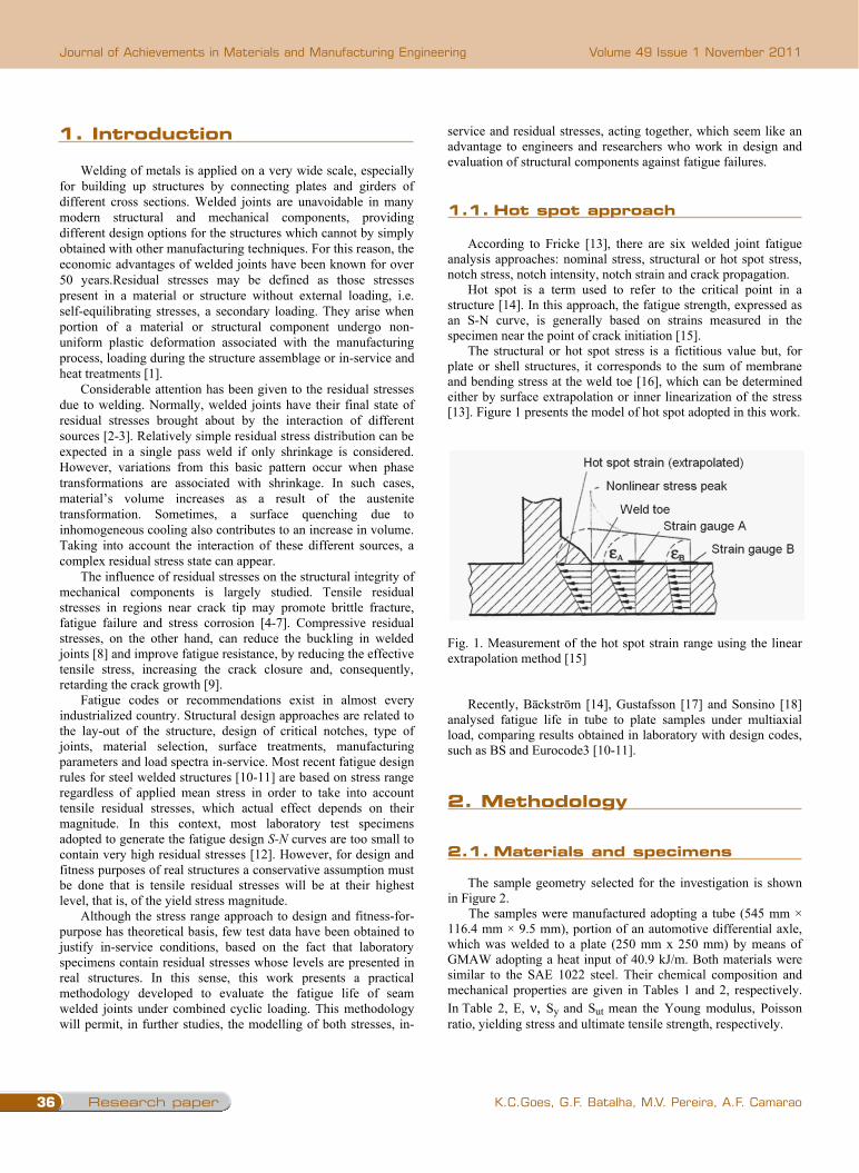
The structural or hot spot stress is a fictitious value but, for plate or shell structures, it corresponds to the sum of membrane and bending stress at the weld toe [16], which can be determined either by surface extrapolation or inner linearization of the stress [13]. Figure 1 presents the model of hot spot adopted in this work.
Fig. 1. Measurement of the hot spot strain range using the linear extrapolation method [15]
Recently, Bäckström [14], Gustafsson [17] and Sonsino [18] analysed fatigue life in tube to plate samples under multiaxial load, comparing results obtained in laboratory with design codes, such as BS and Eurocode3 [10-11].
2. Methodology
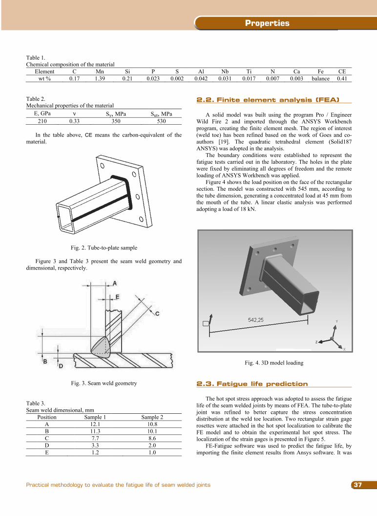
2.1 Materials and specimens The sample geometry selected for the investigation is shown
in Figure 2. The samples were manufactured adopting a tube (545 mm ×
116.4 mm × 9.5 mm), portion of an automotive differential axle, which was welded to a plate (250 mm x 250 mm) by means of GMAW adopting a heat input of 40.9 kJ/m. Both materials were similar to the SAE 1022 steel. Their chemical composition and mechanical properties are given in Tables 1 and 2, respectively. In Table 2, E, , Sy and Sut mean the Young modulus, Poisson ratio, yielding stress and ultimate tensile strength, respectively.
TableChem
E
TableMech
E
In
mate
Fdime
TableSeam
P
e 1. mical compositioElement C
wt % 0.
e 2. hanical propertie
E, GPa 210 0.3
n the table aboerial.
Fi
Figure 3 and Taensional, respecti
F
e 3. m weld dimensioPosition
A B C D E
on of the materiaC Mn 17 1.39
es of the materia Sy
33
ove, CE means
ig. 2. Tube-to-pl
able 3 present tively.
ig. 3. Seam weld
onal, mm Sample 1
12.1 11.3 7.7 3.3 1.2
al Si
0.21 0
al , MPa 350
the carbon-equ
late sample
the seam weld
d geometry
Sam11
P S 0.023 0.002
Sut, MPa 530
ivalent of the
geometry and
mple 2 10.8 10.1 8.6 2.0 1.0
Al N0.042 0.
2.2 Finit
A solidWild Fireprogram, cr(weld toe)authors [1ANSYS) w
The bofatigue testwere fixedloading of A
Figure 4section. Ththe tube dimthe mouth adopting a l
2.3 Fatig
The hot
life of the sjoint was distributionrosettes weFE model localization
FE-Fatiimporting t
Nb Ti 031 0.017
te element a
d model was bu2 and import
reating the finitehas been refine
19]. The quadwas adopted in thoundary conditiots carried out inby eliminating
ANSYS Workbe4 shows the load
he model was comension, generatof the tube. A load of 18 kN.
Fig. 4.
gue life pred
t spot stress apprseam welded join
refined to betn at the weld toeere attached in th
and to obtain tn of the strain gaigue software wthe finite elemen
N C0.007 0.0
analysis (FE
uilt using the pred through thee element mesh
ed based on the dratic tetrahedrahe analysis. ons were establ
the laboratory. all degrees of fr
ench was appliedd position on theonstructed with ting a concentratlinear elastic a
3D model loadi
diction
roach was adoptnts by means of tter capture thee location. Two he hot spot locathe experimenta
ages is presentedwas used to prednt results from A
Ca Fe 003 balance
EA)
rogram Pro / Ee ANSYS Wor. The region ofwork of Goes
al element (S
lished to represThe holes in th
freedom and the d. e face of the rect545 mm, accorted load at 45 m
analysis was per
ing
ted to assess theFEA. The tube-e stress concenrectangular stra
alization to calibal hot spot stre
d in Figure 5. dict the fatigue Ansys software.
CE 0.41
Engineer rkbench interest and co-olid187
sent the he plate remote
tangular rding to
mm from rformed
fatigue to-plate ntration
ain gage rate the ss. The
life, by . It was
1. Introduction
2. Methodology
1.1. Hot spot approach
2.1. Materials and specimens
37
Properties
Practical methodology to evaluate the fatigue life of seam welded joints
1. Introduction
Welding of metals is applied on a very wide scale, especially for building up structures by connecting plates and girders of different cross sections. Welded joints are unavoidable in many modern structural and mechanical components, providing different design options for the structures which cannot by simply obtained with other manufacturing techniques. For this reason, the economic advantages of welded joints have been known for over 50 years.Residual stresses may be defined as those stresses present in a material or structure without external loading, i.e. self-equilibrating stresses, a secondary loading. They arise when portion of a material or structural component undergo non- uniform plastic deformation associated with the manufacturing process, loading during the structure assemblage or in-service and heat treatments [1].
Considerable attention has been given to the residual stresses due to welding. Normally, welded joints have their final state of residual stresses brought about by the interaction of different sources [2-3]. Relatively simple residual stress distribution can be expected in a single pass weld if only shrinkage is considered. However, variations from this basic pattern occur when phase transformations are associated with shrinkage. In such cases, material’s volume increases as a result of the austenite transformation. Sometimes, a surface quenching due to inhomogeneous cooling also contributes to an increase in volume. Taking into account the interaction of these different sources, a complex residual stress state can appear.
The influence of residual stresses on the structural integrity of mechanical components is largely studied. Tensile residual stresses in regions near crack tip may promote brittle fracture, fatigue failure and stress corrosion [4-7]. Compressive residual stresses, on the other hand, can reduce the buckling in welded joints [8] and improve fatigue resistance, by reducing the effective tensile stress, increasing the crack closure and, consequently, retarding the crack growth [9].
Fatigue codes or recommendations exist in almost every industrialized country. Structural design approaches are related to the lay-out of the structure, design of critical notches, type of joints, material selection, surface treatments, manufacturing parameters and load spectra in-service. Most recent fatigue design rules for steel welded structures [10-11] are based on stress range regardless of applied mean stress in order to take into account tensile residual stresses, which actual effect depends on their magnitude. In this context, most laboratory test specimens adopted to generate the fatigue design S-N curves are too small to contain very high residual stresses [12]. However, for design and fitness purposes of real structures a conservative assumption must be done that is tensile residual stresses will be at their highest level, that is, of the yield stress magnitude.
Although the stress range approach to design and fitness-for-purpose has theoretical basis, few test data have been obtained to justify in-service conditions, based on the fact that laboratory specimens contain residual stresses whose levels are presented in real structures. In this sense, this work presents a practical methodology developed to evaluate the fatigue life of seam welded joints under combined cyclic loading. This methodology will permit, in further studies, the modelling of both stresses, in-
service and residual stresses, acting together, which seem like an advantage to engineers and researchers who work in design and evaluation of structural components against fatigue failures. 1.1 Hot spot approach
According to Fricke [13], there are six welded joint fatigue
analysis approaches: nominal stress, structural or hot spot stress, notch stress, notch intensity, notch strain and crack propagation.
Hot spot is a term used to refer to the critical point in a structure [14]. In this approach, the fatigue strength, expressed as an S-N curve, is generally based on strains measured in the specimen near the point of crack initiation [15].
The structural or hot spot stress is a fictitious value but, for plate or shell structures, it corresponds to the sum of membrane and bending stress at the weld toe [16], which can be determined either by surface extrapolation or inner linearization of the stress [13]. Figure 1 presents the model of hot spot adopted in this work.
Fig. 1. Measurement of the hot spot strain range using the linear extrapolation method [15]
Recently, Bäckström [14], Gustafsson [17] and Sonsino [18] analysed fatigue life in tube to plate samples under multiaxial load, comparing results obtained in laboratory with design codes, such as BS and Eurocode3 [10-11].
2. Methodology
2.1 Materials and specimens The sample geometry selected for the investigation is shown
in Figure 2. The samples were manufactured adopting a tube (545 mm ×
116.4 mm × 9.5 mm), portion of an automotive differential axle, which was welded to a plate (250 mm x 250 mm) by means of GMAW adopting a heat input of 40.9 kJ/m. Both materials were similar to the SAE 1022 steel. Their chemical composition and mechanical properties are given in Tables 1 and 2, respectively. In Table 2, E, , Sy and Sut mean the Young modulus, Poisson ratio, yielding stress and ultimate tensile strength, respectively.
TableChem
E
TableMech
E
In
mate
Fdime
TableSeam
P
e 1. mical compositioElement C
wt % 0.
e 2. hanical propertie
E, GPa 210 0.3
n the table aboerial.
Fi
Figure 3 and Taensional, respecti
F
e 3. m weld dimensioPosition
A B C D E
on of the materiaC Mn 17 1.39
es of the materia Sy
33
ove, CE means
ig. 2. Tube-to-pl
able 3 present tively.
ig. 3. Seam weld
onal, mm Sample 1
12.1 11.3 7.7 3.3 1.2
al Si
0.21 0
al , MPa 350
the carbon-equ
late sample
the seam weld
d geometry
Sam11
P S 0.023 0.002
Sut, MPa 530
ivalent of the
geometry and
mple 2 10.8 10.1 8.6 2.0 1.0
Al N0.042 0.
2.2 Finit
A solidWild Fireprogram, cr(weld toe)authors [1ANSYS) w
The bofatigue testwere fixedloading of A
Figure 4section. Ththe tube dimthe mouth adopting a l
2.3 Fatig
The hot
life of the sjoint was distributionrosettes weFE model localization
FE-Fatiimporting t
Nb Ti 031 0.017
te element a
d model was bu2 and import
reating the finitehas been refine
19]. The quadwas adopted in thoundary conditiots carried out inby eliminating
ANSYS Workbe4 shows the load
he model was comension, generatof the tube. A load of 18 kN.
Fig. 4.
gue life pred
t spot stress apprseam welded join
refined to betn at the weld toeere attached in th
and to obtain tn of the strain gaigue software wthe finite elemen
N C0.007 0.0
analysis (FE
uilt using the pred through thee element mesh
ed based on the dratic tetrahedrahe analysis. ons were establ
the laboratory. all degrees of fr
ench was appliedd position on theonstructed with ting a concentratlinear elastic a
3D model loadi
diction
roach was adoptnts by means of tter capture thee location. Two he hot spot locathe experimenta
ages is presentedwas used to prednt results from A
Ca Fe 003 balance
EA)
rogram Pro / Ee ANSYS Wor. The region ofwork of Goes
al element (S
lished to represThe holes in th
freedom and the d. e face of the rect545 mm, accorted load at 45 m
analysis was per
ing
ted to assess theFEA. The tube-e stress concenrectangular stra
alization to calibal hot spot stre
d in Figure 5. dict the fatigue Ansys software.
CE 0.41
Engineer rkbench interest and co-olid187
sent the he plate remote
tangular rding to
mm from rformed
fatigue to-plate ntration
ain gage rate the ss. The
life, by . It was
2.2. Finite element analysis (FEA)
2.3. Fatigue life prediction
Research paper38
Journal of Achievements in Materials and Manufacturing Engineering
K.C.Goes, G.F. Batalha, M.V. Pereira, A.F. Camarao
Volume 49 Issue 1 November 2011
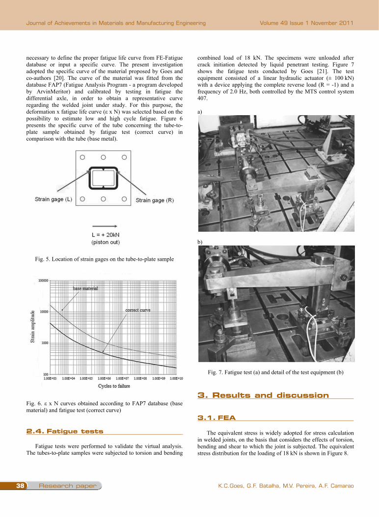
necessary to define the proper fatigue life curve from FE-Fatigue database or input a specific curve. The present investigation adopted the specific curve of the material proposed by Goes and co-authors [20]. The curve of the material was fitted from the database FAP7 (Fatigue Analysis Program - a program developed by ArvinMeritor) and calibrated by testing in fatigue the differential axle, in order to obtain a representative curve regarding the welded joint under study. For this purpose, the deformation x fatigue life curve ( x N) was selected based on the possibility to estimate low and high cycle fatigue. Figure 6 presents the specific curve of the tube concerning the tube-to-plate sample obtained by fatigue test (correct curve) in comparison with the tube (base metal).
Fig. 5. Location of strain gages on the tube-to-plate sample
Fig. 6. x N curves obtained according to FAP7 database (base material) and fatigue test (correct curve)
2.4 Fatigue tests
Fatigue tests were performed to validate the virtual analysis. The tubes-to-plate samples were subjected to torsion and bending
combined load of 18 kN. The specimens were unloaded after crack initiation detected by liquid penetrant testing. Figure 7 shows the fatigue tests conducted by Goes [21]. The test equipment consisted of a linear hydraulic actuator (± 100 kN) with a device applying the complete reverse load (R = -1) and a frequency of 2.0 Hz, both controlled by the MTS control system 407.
a)
b)
Fig. 7. Fatigue test (a) and detail of the test equipment (b)
3. Results and discussion
3.1 FEA
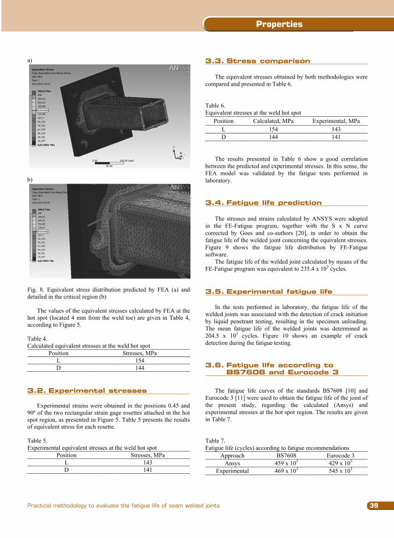
The equivalent stress is widely adopted for stress calculation in welded joints, on the basis that considers the effects of torsion, bending and shear to which the joint is subjected. The equivalent stress distribution for the loading of 18 kN is shown in Figure 8.
a)
b)
Fig. detai
Thot saccor TableCalcu
3.2
E
90º ospot of eq TableExpe
8. Equivalent siled in the critica
The values of thespot (located 4 mrding to Figure 5
e 4. ulated equivalen
Position L D
Experimen
Experimental strof the two rectanregion, as prese
quivalent stress f
e 5. erimental equiva
Position L D
stress distributioal region (b)
e equivalent stremm from the we5.
nt stresses at the
ntal stresses
rains were obtaingular strain gagented in Figure 5for each rosette.
alent stresses at t
on predicted by
esses calculated eld toe) are give
weld hot spot Stresses, MPa
154 144
ned in the positge rosettes attac5. Table 5 prese
the weld hot spotStresses, M
143 141
FEA (a) and
by FEA at the en in Table 4,
a
tions 0.45 and hed in the hot
ents the results
t MPa
3.3 Stres The equ
compared a Table 6. Equivalent
PositionL D
The resbetween theFEA modelaboratory. 3.4 Fatig
The str
in the FE-corrected bfatigue life Figure 9 software.
The fatiFE-Fatigue
3.5 Expe
In the welded joinby liquid pThe mean 204.5 x 1detection du
3.6 FatEurocod
The fatEurocode 3the presenexperimentin Table 7.
Table 7. Fatigue life
ApprAns
Experim
ss comparis
uivalent stressesand presented in
stresses at the wn Calcula
11
sults presented e predicted and el was validate
gue life pred
resses and strain-Fatigue prograby Goes and coof the welded joshows the fati
igue life of the w program was eq
erimental fa
tests performednts was associatepenetrant testing
fatigue life of 03 cycles. Figuuring the fatigue
tigue life ade 3
tigue life curve3 [11] were usednt study, regatal stresses at the
e (cycles) accordroach sys mental
son
s obtained by boTable 6.
weld hot spot ated, MPa 54 44
in Table 6 shoexperimental strd by the fatigu
diction
ns calculated by am, together wo-authors [20], oint concerning igue life distrib
welded joint calcquivalent to 235
atigue life
d in laboratory, ed with the detec
g, resulting in ththe welded join
ure 10 shows e testing.
according t
es of the standad to obtain the faarding the cale hot spot region
ding to fatigue reBS7608
459 x 103 469 x 103
oth methodologi
Experimental, M143 141
ow a good corresses. In this senue tests perform
ANSYS were awith the S x N
in order to obtthe equivalent sbution by FE-
culated by mean.4 x 103 cycles.
the fatigue lifection of crack in
he specimen unlnts was determan example of
to BS7608
ards BS7608 [1atigue life of the lculated (Ansyn. The results ar
ecommendationsEurocode429 x 10545 x 10
es were
MPa
rrelation nse, the med in
adopted N curve tain the stresses. -Fatigue
ns of the
e of the nitiation loading.
mined as f crack
and
10] and joint of s) and re given
s e 3 03 03
3. results and discussion
2.4. Fatigue tests
3.1. FEA
39
Properties
Practical methodology to evaluate the fatigue life of seam welded joints
necessary to define the proper fatigue life curve from FE-Fatigue database or input a specific curve. The present investigation adopted the specific curve of the material proposed by Goes and co-authors [20]. The curve of the material was fitted from the database FAP7 (Fatigue Analysis Program - a program developed by ArvinMeritor) and calibrated by testing in fatigue the differential axle, in order to obtain a representative curve regarding the welded joint under study. For this purpose, the deformation x fatigue life curve ( x N) was selected based on the possibility to estimate low and high cycle fatigue. Figure 6 presents the specific curve of the tube concerning the tube-to-plate sample obtained by fatigue test (correct curve) in comparison with the tube (base metal).
Fig. 5. Location of strain gages on the tube-to-plate sample
Fig. 6. x N curves obtained according to FAP7 database (base material) and fatigue test (correct curve)
2.4 Fatigue tests
Fatigue tests were performed to validate the virtual analysis. The tubes-to-plate samples were subjected to torsion and bending
combined load of 18 kN. The specimens were unloaded after crack initiation detected by liquid penetrant testing. Figure 7 shows the fatigue tests conducted by Goes [21]. The test equipment consisted of a linear hydraulic actuator (± 100 kN) with a device applying the complete reverse load (R = -1) and a frequency of 2.0 Hz, both controlled by the MTS control system 407.
a)
b)
Fig. 7. Fatigue test (a) and detail of the test equipment (b)
3. Results and discussion
3.1 FEA
The equivalent stress is widely adopted for stress calculation in welded joints, on the basis that considers the effects of torsion, bending and shear to which the joint is subjected. The equivalent stress distribution for the loading of 18 kN is shown in Figure 8.
a)
b)
Fig. detai
Thot saccor TableCalcu
3.2
E
90º ospot of eq TableExpe
8. Equivalent siled in the critica
The values of thespot (located 4 mrding to Figure 5
e 4. ulated equivalen
Position L D
Experimen
Experimental strof the two rectanregion, as prese
quivalent stress f
e 5. erimental equiva
Position L D
stress distributioal region (b)
e equivalent stremm from the we5.
nt stresses at the
ntal stresses
rains were obtaingular strain gagented in Figure 5for each rosette.
alent stresses at t
on predicted by
esses calculated eld toe) are give
weld hot spot Stresses, MPa
154 144
ned in the positge rosettes attac5. Table 5 prese
the weld hot spotStresses, M
143 141
FEA (a) and
by FEA at the en in Table 4,
a
tions 0.45 and hed in the hot
ents the results
t MPa
3.3 Stres The equ
compared a Table 6. Equivalent
PositionL D
The resbetween theFEA modelaboratory. 3.4 Fatig
The str
in the FE-corrected bfatigue life Figure 9 software.
The fatiFE-Fatigue
3.5 Expe
In the welded joinby liquid pThe mean 204.5 x 1detection du
3.6 FatEurocod
The fatEurocode 3the presenexperimentin Table 7.
Table 7. Fatigue life
ApprAns
Experim
ss comparis
uivalent stressesand presented in
stresses at the wn Calcula
11
sults presented e predicted and el was validate
gue life pred
resses and strain-Fatigue prograby Goes and coof the welded joshows the fati
igue life of the w program was eq
erimental fa
tests performednts was associatepenetrant testing
fatigue life of 03 cycles. Figuuring the fatigue
tigue life ade 3
tigue life curve3 [11] were usednt study, regatal stresses at the
e (cycles) accordroach sys mental
son
s obtained by boTable 6.
weld hot spot ated, MPa 54 44
in Table 6 shoexperimental strd by the fatigu
diction
ns calculated by am, together wo-authors [20], oint concerning igue life distrib
welded joint calcquivalent to 235
atigue life
d in laboratory, ed with the detec
g, resulting in ththe welded join
ure 10 shows e testing.
according t
es of the standad to obtain the faarding the cale hot spot region
ding to fatigue reBS7608
459 x 103 469 x 103
oth methodologi
Experimental, M143 141
ow a good corresses. In this senue tests perform
ANSYS were awith the S x N
in order to obtthe equivalent sbution by FE-
culated by mean.4 x 103 cycles.
the fatigue lifection of crack in
he specimen unlnts was determan example of
to BS7608
ards BS7608 [1atigue life of the lculated (Ansyn. The results ar
ecommendationsEurocode429 x 10545 x 10
es were
MPa
rrelation nse, the med in
adopted N curve tain the stresses. -Fatigue
ns of the
e of the nitiation loading.
mined as f crack
and
10] and joint of s) and re given
s e 3 03 03
3.2. Experimental stresses
3.3. stress comparison
3.4. Fatigue life prediction
3.5. Experimental fatigue life
3.6. Fatigue life according to bs7608 and Eurocode 3
Research paper40
Journal of Achievements in Materials and Manufacturing Engineering
K.C.Goes, G.F. Batalha, M.V. Pereira, A.F. Camarao
Volume 49 Issue 1 November 2011
a)
b)
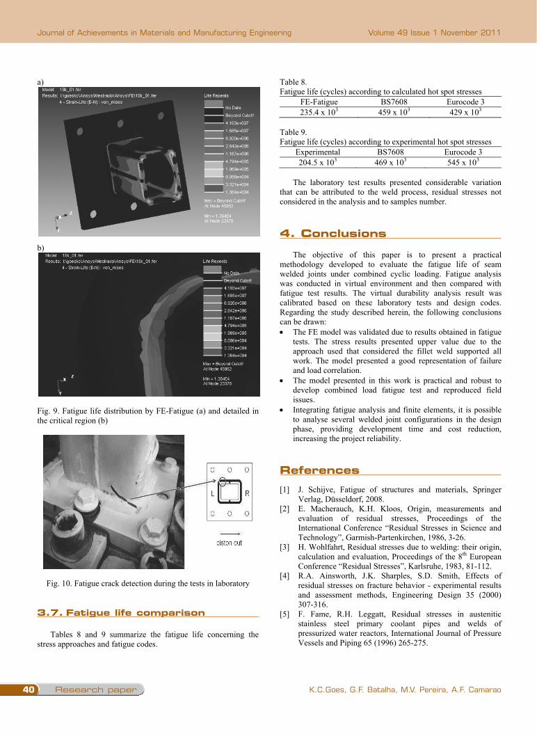
Fig. 9. Fatigue life distribution by FE-Fatigue (a) and detailed in the critical region (b)
Fig. 10. Fatigue crack detection during the tests in laboratory 3.7 Fatigue life comparison
Tables 8 and 9 summarize the fatigue life concerning the stress approaches and fatigue codes.
Table 8. Fatigue life (cycles) according to calculated hot spot stresses
FE-Fatigue BS7608 Eurocode 3 235.4 x 10³ 459 x 103 429 x 103
Table 9. Fatigue life (cycles) according to experimental hot spot stresses
Experimental BS7608 Eurocode 3 204.5 x 10³ 469 x 103 545 x 103
The laboratory test results presented considerable variation
that can be attributed to the weld process, residual stresses not considered in the analysis and to samples number.
4. Conclusions
The objective of this paper is to present a practical methodology developed to evaluate the fatigue life of seam welded joints under combined cyclic loading. Fatigue analysis was conducted in virtual environment and then compared with fatigue test results. The virtual durability analysis result was calibrated based on these laboratory tests and design codes. Regarding the study described herein, the following conclusions can be drawn: The FE model was validated due to results obtained in fatigue
tests. The stress results presented upper value due to the approach used that considered the fillet weld supported all work. The model presented a good representation of failure and load correlation.
The model presented in this work is practical and robust to develop combined load fatigue test and reproduced field issues.
Integrating fatigue analysis and finite elements, it is possible to analyse several welded joint configurations in the design phase, providing development time and cost reduction, increasing the project reliability.
References [1] J. Schijve, Fatigue of structures and materials, Springer
Verlag, Düsseldorf, 2008. [2] E. Macherauch, K.H. Kloos, Origin, measurements and
evaluation of residual stresses, Proceedings of the International Conference “Residual Stresses in Science and Technology”, Garmish-Partenkirchen, 1986, 3-26.
[3] H. Wohlfahrt, Residual stresses due to welding: their origin, calculation and evaluation, Proceedings of the 8th European Conference “Residual Stresses”, Karlsruhe, 1983, 81-112.
[4] R.A. Ainsworth, J.K. Sharples, S.D. Smith, Effects of residual stresses on fracture behavior - experimental results and assessment methods, Engineering Design 35 (2000) 307-316.
[5] F. Fame, R.H. Leggatt, Residual stresses in austenitic stainless steel primary coolant pipes and welds of pressurized water reactors, International Journal of Pressure Vessels and Piping 65 (1996) 265-275.
[6] P. Dong, J.K. Hong, P.J. Bouchard, Analysis of residual stresses at weld repairs, International Journal of Pressure Vessels and Piping 82 (2005) 258-269.
[7] E.J. Mcdonald, K.R. Hallam, P.E.J. Flewitt, A strategy for accommodating residual stresses in the assessment of repair weldments based upon measurement of near surface stresses, International Journal of Pressure Vessels and Piping 82 (2005) 339-346.
[8] K. Masubuchi, Analysis of welded structures, Pergamon Press, New York, 1980.
[9] M.S. Ramos, M.V. Pereira, F.A. Darwish, M.A. Carneiro, Effect of single and multiple overloading on the residual fatigue life of a structural steel, Fatigue and Fracture of Engineering Materials and Structures 26 (2003) 1-7.
[10] British Standards Institution, Eurocode 3 “Design of steel structures”, Part 1-9 “Fatigue strength”, BS EN 1993-1-9, British Standards Institution, London, 2005.
[11] British Standards Institution, BS7608 “Code of practice for Fatigue design and assessment of steel structures”, British Standards Institution, London, 1993.
[12] S.J. Maddox, Influence of tensile residual stresses on the fatigue behavior of welded joints in steel, Proceedings of the Conference “Residual Stresses Effects in Fatigue”, ASTM STP 776, Warrendale, 1982, 63-96.
[13] W. Fricke, Fatigue analysis of welded joints: state of development, Marine Structures 16 (2003) 185-200.
[14] M. Bäckström, Multiaxial fatigue life assessment of welds based on nominal and hot spot stresses, VTT Publications, Helsinki, 2003.
[15] E. Niemi, Stress determination for fatigue analysis of welded components, Abington Publishing, Cambridge, 1995.
[16] D. Radaj, Design and analysis of fatigue resistant welded structures, Abington Publishing, Cambridge, 1990.
[17] J. Gustafsson, Multi-axial fatigue in welded details - an investigation of existing design approaches, MSc Thesis, Chalmers University of Technology, Sweden, 2007.
[18] C.M. Sonsino, Multiaxial fatigue assessment of welded joints - recommendations for design codes, International Journal of Fatigue 31 (2009) 173-187.
[19] K.C. Goes, G.F. Batalha, A.F. Camarao, Finite element modeling techniques of 3D welded joints - the structural hot spot approach, Proceedings of the 20th International Congress of Mechanical Engineering, Gramado, 1 (2009) 1-10.
[20] K.C. Goes, G.F. Batalha, A.F. Camarao, A fatigue analysis model of welded joints within finite element environment, Proceedings of the IIW International Congress / 2nd Latin American Welding Congress / XXXIV CONSOLDA, São Paulo, 2008, 1-10 (CD-ROM).
[21] K.C. Goes, A Model for fatigue life prediction of weldment joints submitted to combined loadings, MSc Thesis, University of Sao Paulo, Brazil, 2010, http://www.teses.usp.br /teses/disponiveis/3/3151/tde20082-152344/ (in Portuguese).
4. conclusions
references
3.7. Fatigue life comparison
41READING DIRECT: www.journalamme.org
Properties
a)
b)
Fig. 9. Fatigue life distribution by FE-Fatigue (a) and detailed in the critical region (b)
Fig. 10. Fatigue crack detection during the tests in laboratory 3.7 Fatigue life comparison
Tables 8 and 9 summarize the fatigue life concerning the stress approaches and fatigue codes.
Table 8. Fatigue life (cycles) according to calculated hot spot stresses
FE-Fatigue BS7608 Eurocode 3 235.4 x 10³ 459 x 103 429 x 103
Table 9. Fatigue life (cycles) according to experimental hot spot stresses
Experimental BS7608 Eurocode 3 204.5 x 10³ 469 x 103 545 x 103
The laboratory test results presented considerable variation
that can be attributed to the weld process, residual stresses not considered in the analysis and to samples number.
4. Conclusions
The objective of this paper is to present a practical methodology developed to evaluate the fatigue life of seam welded joints under combined cyclic loading. Fatigue analysis was conducted in virtual environment and then compared with fatigue test results. The virtual durability analysis result was calibrated based on these laboratory tests and design codes. Regarding the study described herein, the following conclusions can be drawn: The FE model was validated due to results obtained in fatigue
tests. The stress results presented upper value due to the approach used that considered the fillet weld supported all work. The model presented a good representation of failure and load correlation.
The model presented in this work is practical and robust to develop combined load fatigue test and reproduced field issues.
Integrating fatigue analysis and finite elements, it is possible to analyse several welded joint configurations in the design phase, providing development time and cost reduction, increasing the project reliability.
References [1] J. Schijve, Fatigue of structures and materials, Springer
Verlag, Düsseldorf, 2008. [2] E. Macherauch, K.H. Kloos, Origin, measurements and
evaluation of residual stresses, Proceedings of the International Conference “Residual Stresses in Science and Technology”, Garmish-Partenkirchen, 1986, 3-26.
[3] H. Wohlfahrt, Residual stresses due to welding: their origin, calculation and evaluation, Proceedings of the 8th European Conference “Residual Stresses”, Karlsruhe, 1983, 81-112.
[4] R.A. Ainsworth, J.K. Sharples, S.D. Smith, Effects of residual stresses on fracture behavior - experimental results and assessment methods, Engineering Design 35 (2000) 307-316.
[5] F. Fame, R.H. Leggatt, Residual stresses in austenitic stainless steel primary coolant pipes and welds of pressurized water reactors, International Journal of Pressure Vessels and Piping 65 (1996) 265-275.
[6] P. Dong, J.K. Hong, P.J. Bouchard, Analysis of residual stresses at weld repairs, International Journal of Pressure Vessels and Piping 82 (2005) 258-269.
[7] E.J. Mcdonald, K.R. Hallam, P.E.J. Flewitt, A strategy for accommodating residual stresses in the assessment of repair weldments based upon measurement of near surface stresses, International Journal of Pressure Vessels and Piping 82 (2005) 339-346.
[8] K. Masubuchi, Analysis of welded structures, Pergamon Press, New York, 1980.
[9] M.S. Ramos, M.V. Pereira, F.A. Darwish, M.A. Carneiro, Effect of single and multiple overloading on the residual fatigue life of a structural steel, Fatigue and Fracture of Engineering Materials and Structures 26 (2003) 1-7.
[10] British Standards Institution, Eurocode 3 “Design of steel structures”, Part 1-9 “Fatigue strength”, BS EN 1993-1-9, British Standards Institution, London, 2005.
[11] British Standards Institution, BS7608 “Code of practice for Fatigue design and assessment of steel structures”, British Standards Institution, London, 1993.
[12] S.J. Maddox, Influence of tensile residual stresses on the fatigue behavior of welded joints in steel, Proceedings of the Conference “Residual Stresses Effects in Fatigue”, ASTM STP 776, Warrendale, 1982, 63-96.
[13] W. Fricke, Fatigue analysis of welded joints: state of development, Marine Structures 16 (2003) 185-200.
[14] M. Bäckström, Multiaxial fatigue life assessment of welds based on nominal and hot spot stresses, VTT Publications, Helsinki, 2003.
[15] E. Niemi, Stress determination for fatigue analysis of welded components, Abington Publishing, Cambridge, 1995.
[16] D. Radaj, Design and analysis of fatigue resistant welded structures, Abington Publishing, Cambridge, 1990.
[17] J. Gustafsson, Multi-axial fatigue in welded details - an investigation of existing design approaches, MSc Thesis, Chalmers University of Technology, Sweden, 2007.
[18] C.M. Sonsino, Multiaxial fatigue assessment of welded joints - recommendations for design codes, International Journal of Fatigue 31 (2009) 173-187.
[19] K.C. Goes, G.F. Batalha, A.F. Camarao, Finite element modeling techniques of 3D welded joints - the structural hot spot approach, Proceedings of the 20th International Congress of Mechanical Engineering, Gramado, 1 (2009) 1-10.
[20] K.C. Goes, G.F. Batalha, A.F. Camarao, A fatigue analysis model of welded joints within finite element environment, Proceedings of the IIW International Congress / 2nd Latin American Welding Congress / XXXIV CONSOLDA, São Paulo, 2008, 1-10 (CD-ROM).
[21] K.C. Goes, A Model for fatigue life prediction of weldment joints submitted to combined loadings, MSc Thesis, University of Sao Paulo, Brazil, 2010, http://www.teses.usp.br /teses/disponiveis/3/3151/tde20082-152344/ (in Portuguese).