Practical Grounding/Earthing, Shielding, EMC/EMI and ... · PDF filePresents Practical...
25
Presents Practical Grounding/Earthing, Shielding, EMC/EMI and Circuit Board Layout of Electronic Systems Web Site:www.idc-online.com E-mail: [email protected]
Transcript of Practical Grounding/Earthing, Shielding, EMC/EMI and ... · PDF filePresents Practical...
Presents
Practical Grounding/Earthing, Shielding, EMC/EMI
and Circuit Board Layout of Electronic Systems
Web Site:www.idc-online.com E-mail: [email protected]
Copyright All rights to this publication, associated software and workshop are reserved. No part of this publication or associated software may be copied, reproduced, transmitted or stored in any form or by any means (including electronic, mechanical, photocopying, recording or otherwise) without prior written permission of IDC Technologies.
Disclaimer Whilst all reasonable care has been taken to ensure that the descriptions, opinions, programs, listings, software and diagrams are accurate and workable, IDC Technologies do not accept any legal responsibility or liability to any person, organization or other entity for any direct loss, consequential loss or damage, however caused, that may be suffered as a result of the use of this publication or the associated workshop and software.
In case of any uncertainty, we recommend that you contact IDC Technologies for clarification or assistance.
Trademarks All terms noted in this publication that are believed to be registered trademarks or trademarks are listed below:
IBM, XT and AT are registered trademarks of International Business Machines Corporation. Microsoft, MS-DOS and Windows are registered trademarks of Microsoft Corporation.
Acknowledgements IDC Technologies expresses its sincere thanks to all those engineers and technicians on our training workshops who freely made available their expertise in preparing this manual.
Who is IDC Technologies? IDC Technologies is a specialist in the field of industrial communications, telecommunications, automation and control and has been providing high quality training for more than six years on an international basis from offices around the world.
IDC consists of an enthusiastic team of professional engineers and support staff who are committed to providing the highest quality in their consulting and training services. The Benefits to you of Technical Training Today The technological world today presents tremendous challenges to engineers, scientists and technicians in keeping up to date and taking advantage of the latest developments in the key technology areas.
• The immediate benefits of attending IDC workshops are: • Gain practical hands-on experience • Enhance your expertise and credibility • Save $$$s for your company • Obtain state of the art knowledge for your company • Learn new approaches to troubleshooting • Improve your future career prospects The IDC Approach to Training All workshops have been carefully structured to ensure that attendees gain maximum benefits. A combination of carefully designed training software, hardware and well written documentation, together with multimedia techniques ensure that the workshops are presented in an interesting, stimulating and logical fashion.
IDC has structured a number of workshops to cover the major areas of technology. These courses are presented by instructors who are experts in their fields, and have been attended by thousands of engineers, technicians and scientists world-wide (over 11,000 in the past two years), who have given excellent reviews. The IDC team of professional engineers is constantly reviewing the courses and talking to industry leaders in these fields, thus keeping the workshops topical and up to date.
Technical Training Workshops IDC is continually developing high quality state of the art workshops aimed at assisting engineers, technicians and scientists. Current workshops include:
Instrumentation & Control • Practical Automation and Process Control using PLC’s • Practical Data Acquisition using Personal Computers and Standalone Systems • Practical On-line Analytical Instrumentation for Engineers and Technicians • Practical Flow Measurement for Engineers and Technicians • Practical Intrinsic Safety for Engineers and Technicians • Practical Safety Instrumentation and Shut-down Systems for Industry • Practical Process Control for Engineers and Technicians • Practical Programming for Industrial Control – using (IEC 1131-3;OPC) • Practical SCADA Systems for Industry • Practical Boiler Control and Instrumentation for Engineers and Technicians • Practical Process Instrumentation for Engineers and Technicians • Practical Motion Control for Engineers and Technicians • Practical Communications, SCADA & PLC’s for Managers Communications • Practical Data Communications for Engineers and Technicians • Practical Essentials of SNMP Network Management • Practical Field Bus and Device Networks for Engineers and Technicians • Practical Industrial Communication Protocols • Practical Fibre Optics for Engineers and Technicians • Practical Industrial Networking for Engineers and Technicians • Practical TCP/IP & Ethernet Networking for Industry • Practical Telecommunications for Engineers and Technicians • Practical Radio & Telemetry Systems for Industry • Practical Local Area Networks for Engineers and Technicians • Practical Mobile Radio Systems for Industry
Electrical • Practical Power Systems Protection for Engineers and Technicians • Practical High Voltage Safety Operating Procedures for Engineers & Technicians • Practical Solutions to Power Quality Problems for Engineers and Technicians • Practical Communications and Automation for Electrical Networks • Practical Power Distribution • Practical Variable Speed Drives for Instrumentation and Control Systems Project & Financial Management • Practical Project Management for Engineers and Technicians • Practical Financial Management and Project Investment Analysis • How to Manage Consultants Mechanical Engineering • Practical Boiler Plant Operation and Management for Engineers and Technicians • Practical Centrifugal Pumps – Efficient use for Safety & Reliability Electronics • Practical Digital Signal Processing Systems for Engineers and Technicians • Practical Industrial Electronics Workshop • Practical Image Processing and Applications • Practical EMC and EMI Control for Engineers and Technicians Information Technology • Personal Computer & Network Security (Protect from Hackers, Crackers & Viruses) • Practical Guide to MCSE Certification • Practical Application Development for Web Based SCADA
Comprehensive Training Materials Workshop Documentation All IDC workshops are fully documented with complete reference materials including comprehensive manuals and practical reference guides.
Software Relevant software is supplied with most workshops. The software consists of demonstration programs which illustrate the basic theory as well as the more difficult concepts of the workshop.
Hands-On Approach to Training The IDC engineers have developed the workshops based on the practical consulting expertise that has been built up over the years in various specialist areas. The objective of training today is to gain knowledge and experience in the latest developments in technology through cost effective methods. The investment in training made by companies and individuals is growing each year as the need to keep topical and up to date in the industry which they are operating is recognized. As a result, the IDC instructors place particular emphasis on the practical hands-on aspect of the workshops presented.
On-Site Workshops In addition to the quality of workshops which IDC presents on a world-wide basis, all IDC courses are also available for on-site (in-house) presentation at our clients’ premises. On-site training is a cost effective method of training for companies with many delegates to train in a particular area. Organizations can save valuable training $$$’s by holding courses on-site, where costs are significantly less. Other benefits are IDC’s ability to focus on particular systems and equipment so that attendees obtain only the greatest benefits from the training.
All on-site workshops are tailored to meet with clients training requirements and courses can be presented at beginners, intermediate or advanced levels based on the knowledge and experience of delegates in attendance. Specific areas of interest to the client can also be covered in more detail. Our external workshops are planned well in advance and you should contact us as early as possible if you require on-site/customized training. While we will always endeavor to meet your timetable preferences, two to three month’s notice is preferable in order to successfully fulfil your requirements. Please don’t hesitate to contact us if you would like to discuss your training needs.
Customized Training In addition to standard on-site training, IDC specializes in customized courses to meet client training specifications. IDC has the necessary engineering and training expertise and resources to work closely with clients in preparing and presenting specialized courses.
These courses may comprise a combination of all IDC courses along with additional topics and subjects that are required. The benefits to companies in using training are reflected in the increased efficiency of their operations and equipment.
Training Contracts IDC also specializes in establishing training contracts with companies who require ongoing training for their employees. These contracts can be established over a given period of time and special fees are negotiated with clients based on their requirements. Where possible, IDC will also adapt courses to satisfy your training budget.
References from various international companies to whom IDC is contracted to provide on-going technical training are available on request.
Some of the thousands of Companies worldwide that have supported and benefited from IDC workshops are: Alcoa, Allen-Bradley, Altona Petrochemical, Aluminum Company of America, AMC Mineral Sands, Amgen, Arco Oil and Gas, Argyle Diamond Mine, Associated Pulp and Paper Mill, Bailey Controls, Bechtel, BHP Engineering, Caltex Refining, Canon, Chevron, Coca-Cola, Colgate-Palmolive, Conoco Inc, Dow Chemical, ESKOM, Exxon, Ford, Gillette Company, Honda, Honeywell, Kodak, Lever Brothers, McDonnell Douglas, Mobil, Modicon, Monsanto, Motorola, Nabisco, NASA, National Instruments, National Semi-Conductor, Omron Electric, Pacific Power, Pirelli Cables, Proctor and Gamble, Robert Bosch Corp, Siemens, Smith Kline Beecham, Square D, Texaco,Varian,Warner Lambert, Woodside Offshore Petroleum, Zener Electric

Contents
1 Introduction 1 1.1 Introduction 1 1.2 EMI vs EMC 3 1.3 Interference sources 3 1.4 Need for standards 5 1.5 EMC – the issues 6 1.6 Electromagnetic disturbances 7 1.7 EMC testing categories 8 1.8 The compatibility gap 9 1.9 Emission, immunity and compatibility 10 1.10 Causes and consequences of EMI 11 1.11 Levels of compliance and EMC engineering application 12
2 EM principles 14 2.1 Introduction 14 2.2 Coupling paths: sources and victims 14 2.3 Coupling mechanisms 17 2.4 Coupling via the supply network 20 2.5 Electromagnetic fields 21 2.6 Rayleigh/Maxwell near/far fields 22 2.7 Coupling modes 23 2.8 Radiated emissions from PCB (differential mode) 24 2.9 Cable radiated emissions (common mode) 25 2.10 Coupling paths (conducted emissions) 26 2.11 Susceptibility to radiated field coupling 27 2.12 Transient sources 28 2.13 Automotive transients 29 2.14 Supply voltage phenomenon 30
3 EM principles - 2 32 3.1 Introduction 32 3.2 DM/CM conversion 32 3.3 Common mode rejection ratio (CMRR) 34 3.4 Units in EMC engineering 34 3.5 Spectrum usage and created Interference 36 3.6 Fourier analysis 37 3.7 Choice of logic family 39 3.8 Lightning and ESD bandwidth 39
2 Contents
4 Shielding 40 4.1 Introduction 40 4.2 Shielding and Murphy’s Law 41 4.3 LF magnetic shielding 43 4.4 Apertures and shielding effectiveness 43 4.5 Waveguides 44 4.6 Gasketting and sealing 45 4.7 Panel displays and keyboards 46 4.8 Ventilation and shielding 47 4.9 PCB-level shielding 49
5 Grounding 50 5.1 Introduction 50 5.2 Earth and safety ground 51 5.3 Grounding and frequency 53 5.4 Ground loops 54 5.5 Ground impedance 55 5.6 Ground topologies 55 5.7 Guidelines for grounding 57
6 Cables and connectors 60 6.1 Introduction 60 6.2 Cables in context 61 6.3 Cable parameters and implication 62 6.4 Cable types and frequency 62 6.5 Cable routing and screening 63 6.6 Types of screening 66 6.7 Screened and unscreened connectors 67 6.8 Transmission lines 69 6.9 Cable coupling to radiated field 71 6.10 Useful references 71
7 Circuits and components 72 7.1 Introduction 72 7.2 Parasitic in passives 73 7.3 Clocking 74 7.4 Choice of logic family 75 7.5 Design and component choice 75 7.6 Analog immunity and demodulation 76
8 Protection and filtering 80 8.1 Introduction 80 8.2 Filter types and operation 81
Contents 3
8.3 Soft ferrites 82 8.4 Thumb rules 83 8.5 Filter specifications 84 8.6 Impedance matching 85 8.7 Filtering precision and Filter earthing 86 8.8 Filters and shielding 87 8.9 Surge protection devices (SPDs) 88 8.10 Surge protection and data integrity 89 8.11 Surge protection ratings 90 8.12 Surge protection fusing 91 8.13 Positioning SPDs 92 8.14 Electrostatic discharge 93 8.15 Creepage and clearance 94 8.16 Shielding 95 8.17 Signal line protection 97
9 Engineering measurements 99 9.1 Introduction 99 9.2 Bench and test laboratory 99 9.3 Determining common mode noise 101 9.4 Field probes 103 9.5 Common mode and Differential mode currents 105
10 Power supplies 107 10.1 Introduction 107 10.2 PSUs as noise generators 108 10.3 Switch-mode PSU as a noise generator 109 10.4 Coupling paths, conducted emissions 109 10.5 Power supplies 110 10.6 Parasitic components in SMPS 110 10.7 Effects of diodes 111 10.8 Improvements from inductors 111 10.9 The mains filter 112 10.10 PSU threats 114
11 PCB design and layout 115 11.1 Introduction 115 11.2 Levels of EMC Engineering Application 116 11.3 PCB design objectives 117 11.4 Differential mode coupling 117 11.5 Common mode coupling 118 11.6 Electrical and physical parameters 119 11.7 Board layout 120 11.8 Component and track layout 120
4 Contents
11.9 Areas under control vs outside 121 11.10 Reference planes 122 11.11 The Image Plane effect 123 11.12 Maintaining plane integrity and gridded ground 124 11.13 Board layering 126 11.14 Layer stacking 126 11.15 Grounding on the board 129 11.16 0 V – Chassis Connection 131 11.17 Decoupling Capacitors 132 11.18 Transmission Lines on PCBs 134 11.19 Transmission line termination 135 11.20 Multiple boards and backplanes 136 11.21 Interfacing noisy and quite areas 136
12 EMC engineering management 137 12.1 Introduction 137 12.2 Why manage EMC? 137 12.3 Wait and its too late 139 12.4 How to manage EMC 139 12.5 Levels of compliance 141 12.6 EMC lifecycle 142 12.7 Life-cycle flow chart 143 12.8 EMC in context 144 12.9 How much effort? 144 12.10 Co-ordinating efforts 144 12.11 Design practices 145 12.12 EMC engineering implementation 145 12.13 Project management 146 12.14 Need for control plan 146 12.15 Test plans 147 12.16 Test reports (immunity) 149 12.17 Test and calibration of facilities 149 12.18 Maintaining EMC in production 150
13 Conclusion 151 13.1 Introduction 151 13.2 EMC Legalities 152
14 Tutorials 154
15 Practical Exercises 162
16 Powerpoint Slides 178
1
Introduction
1.1 Introduction Electromagnetic Compatibility (EMC) is defined as the ability of a device, equipment or a system to function satisfactorily in its electromagnetic environment without introducing intolerable electromagnetic disturbance to anything in that environment. Any electronic equipment is both capable of emitting unintended signals (i.e., interference to other electronic equipment) and also itself being affected by spurious radiation from other electronic equipment (i.e., interference caused by other electronic equipment). Putting these electronics together without affecting each other is the challenge. Meeting the challenge is a combination of legislation, engineering and consideration for the needs of others.
1.1.1 EMC – accepting the challenge!!! Historically, EMC has been concerned principally with ensuring the proper operation of collections of electrical and electronic apparatus. Since interference is a function of separation distance, equipment used in close proximity to other equipment had to be compatible with its neighbors. Putting together a system out of several essentially different items of apparatus meant that these items were naturally close to each other, and their Electromagnetic Compatibility (EMC) was necessary in order for the system to work successfully. Hence the discipline of EMC grew up in those industry sectors where system integration was the norm. In the military, the majority of electrical and electronics equipment is used on platforms i.e., ships, aircraft and land vehicles, in their civilian equivalents, aerospace, rail, automotive and marine transport, and in the process control industry. The consumer, IT and professional equipment sectors largely escaped this discipline, because their individual products could assume a large enough separation distance that EMC could be regarded as a luxury rather than a necessity.
Commercial systems that faced issues of safety integrity had often to meet requirements for immunity from various phenomena such as radio frequency (RF) fields, electrostatic discharge (ESD), and various types of conducted transients. But these were contractual requirements, agreed between the equipment suppliers, and the system

2 Practical Shielding, EMC/EMI, Noise Reduction, Earthing and Circuit Board Layout
designers and operators. They were instigated as a result of operational experience, not because of legislation.
There is now an urgent need for mandatory measures to be taken to protect and ensure equipment EMC. Various national administrators have taken ad hoc measures in the past to impose restrictions on some of the electromagnetic properties of some types of products. These measures have often come to be seen as implementing back-door methods of protection, without the technical adequacy of some of the requirements allowing effectively different standards to be applied to imported and indigenous products. In an effort to recognize the need for EMC protection measures and at the same time to eliminate the protectionist barrier to trade throughout the European Community, the European Commission adopted in 1989 a Directive on the approximation of the laws of the Member States relative to electromagnetic compatibility, otherwise known as the EMC Directive.
At times, EMC problems and their solutions do seem like black magic rather than engineering. Here are few of the examples…
• This is an instance from the Falklands war: HMS Sheffield turned off its missile warning RADAR because it interfered with the satellite communication system of the ship. The result of this was – HMS Sheffield was sunk by an enemy missile, which could otherwise have been detected.
• An engineering company installed a CAD system to speed up design time. However, the system crashed so often that they were falling even further behind. Numerous calls to the suppliers failed to solve the problem that everyone thought was software-related. Investigation showed eventually that a large drawing reproduction machine that injected transients onto the mains supply caused it.
• In February ’99, while approaching JFK airport, a DC 10 passenger airplane banked hard left all by itself, almost crashing. The cause of it was suspected to be a CD player being played in 1st class.
• Much of the bad press surrounding CD players and aircraft seems to have originated with a Lufthansa flight where a system operating at 112 MHz had problems which were traced to a CD player with a clock rate of 28 MHz. The system operating frequency is equal to 4 times the clock rate of the CD player.
• A paper mill in Stanger (South Africa) was experiencing trips on its 1 MVA variable speed drive system. A voltage dip of 20%, lasting for more than 40 ms was enough to trip the system and would result in several hours of downtime while the paper web was re-threaded and the system started up again. Installation of a SMES (Superconducting Magnetic Energy Storage System) has meant that there have been no further system trips since 1997.
• In an aerospace factory, a plastic welder was being operated quite legally. Nearby is a mattress factory. Although both are tens of meters away from each other, the welder caused a mattress to burst into flames.
Here is a statement (which may sound familiar) given by the past chairman of the
Scottish branch of the Institute of Structural Engineers ‘ … the art of modelling materials we do not understand, into shapes we cannot precisely analyse, to withstand forces we cannot properly assess, in such a way that the public at large has no reason to suspect the extent of our ignorance’.
In this workshop, we will be looking at engineering ways to prevent and solve EMC problems without the need for witches, wizards and other supernatural means.
Introduction 3
1.2 EMI vs EMC Electromagnetic interference (EMI) is a serious and increasing form of environmental pollution. Its effects range from extremely small annoyances due to crackles on broadcast reception, to potentially fatal accidents due to corruption of safety-critical control systems. Various forms of EMI may cause electrical and electronic malfunctions, can prevent the proper use of the radio frequency spectrum, can ignite flammable or other hazardous atmospheres, and may even have a direct effect on human tissue. As electronic systems penetrate more deeply into all aspects of society, so both the potential for interference effects and the potential for serious EMI-induced incidents will increase.
The threat of EMI is controlled by adopting the practices of electromagnetic compatibility (EMC). The term EMC has two complementary aspects:
• It describes the ability of electrical and electronic systems to operate without interfering with other systems
• It also describes the ability of such systems to operate as intended within a specified electromagnetic environment
Thus it is closely related to the environment within which the system operates.
Effective EMC requires that the system is designed, manufactured and tested with regard to its predicted operational electromagnetic environmental (i.e., the totality of electromagnetic phenomena existing at its location). Although the term electromagnetic tends to suggest an emphasis on high frequency field-related phenomena, in practice the definition of EMC encompasses all frequencies and coupling paths, from DC through mains supply frequencies and microwaves.
1.3 Interference sources
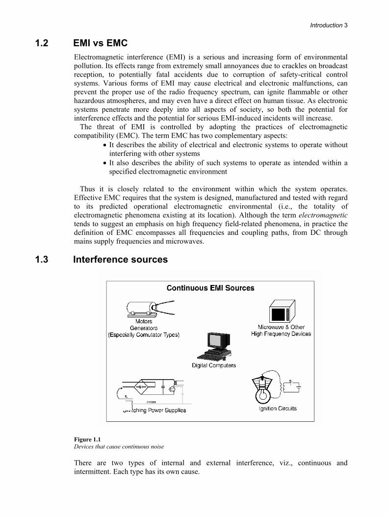
Figure 1.1 Devices that cause continuous noise
There are two types of internal and external interference, viz., continuous and intermittent. Each type has its own cause.
4 Practical Shielding, EMC/EMI, Noise Reduction, Earthing and Circuit Board Layout
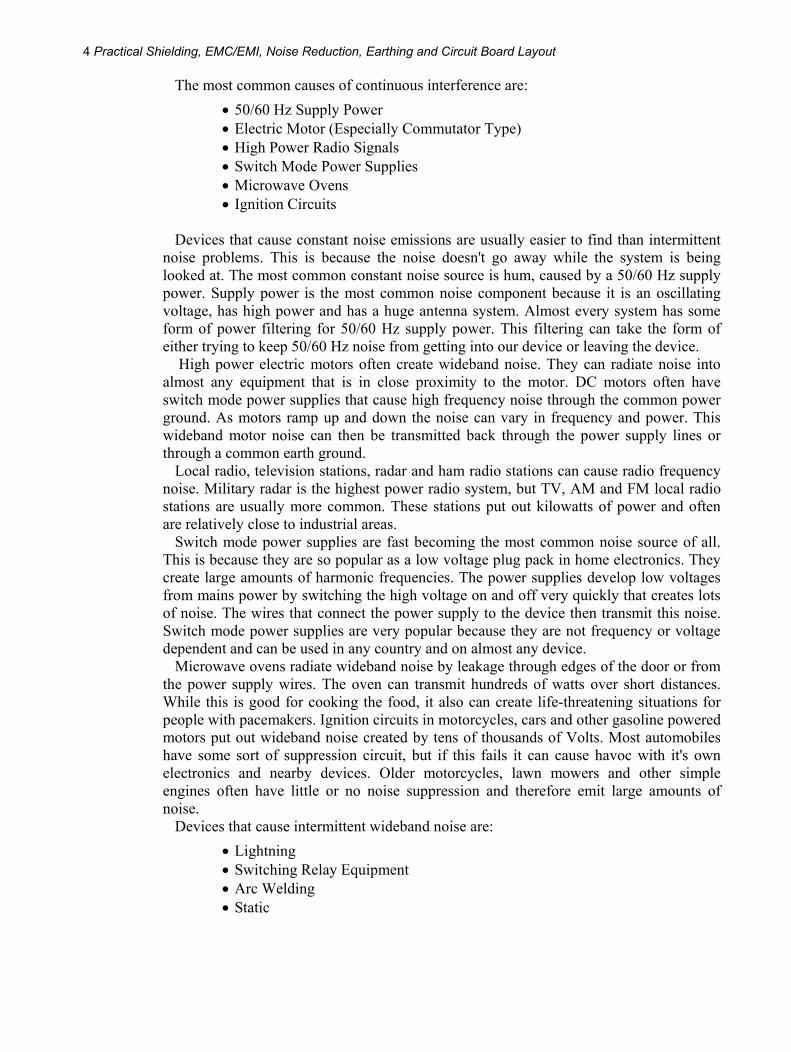
The most common causes of continuous interference are: • 50/60 Hz Supply Power • Electric Motor (Especially Commutator Type) • High Power Radio Signals • Switch Mode Power Supplies • Microwave Ovens • Ignition Circuits
Devices that cause constant noise emissions are usually easier to find than intermittent
noise problems. This is because the noise doesn't go away while the system is being looked at. The most common constant noise source is hum, caused by a 50/60 Hz supply power. Supply power is the most common noise component because it is an oscillating voltage, has high power and has a huge antenna system. Almost every system has some form of power filtering for 50/60 Hz supply power. This filtering can take the form of either trying to keep 50/60 Hz noise from getting into our device or leaving the device.
High power electric motors often create wideband noise. They can radiate noise into almost any equipment that is in close proximity to the motor. DC motors often have switch mode power supplies that cause high frequency noise through the common power ground. As motors ramp up and down the noise can vary in frequency and power. This wideband motor noise can then be transmitted back through the power supply lines or through a common earth ground.
Local radio, television stations, radar and ham radio stations can cause radio frequency noise. Military radar is the highest power radio system, but TV, AM and FM local radio stations are usually more common. These stations put out kilowatts of power and often are relatively close to industrial areas.
Switch mode power supplies are fast becoming the most common noise source of all. This is because they are so popular as a low voltage plug pack in home electronics. They create large amounts of harmonic frequencies. The power supplies develop low voltages from mains power by switching the high voltage on and off very quickly that creates lots of noise. The wires that connect the power supply to the device then transmit this noise. Switch mode power supplies are very popular because they are not frequency or voltage dependent and can be used in any country and on almost any device.
Microwave ovens radiate wideband noise by leakage through edges of the door or from the power supply wires. The oven can transmit hundreds of watts over short distances. While this is good for cooking the food, it also can create life-threatening situations for people with pacemakers. Ignition circuits in motorcycles, cars and other gasoline powered motors put out wideband noise created by tens of thousands of Volts. Most automobiles have some sort of suppression circuit, but if this fails it can cause havoc with it's own electronics and nearby devices. Older motorcycles, lawn mowers and other simple engines often have little or no noise suppression and therefore emit large amounts of noise.
Devices that cause intermittent wideband noise are: • Lightning • Switching Relay Equipment • Arc Welding • Static
Introduction 5
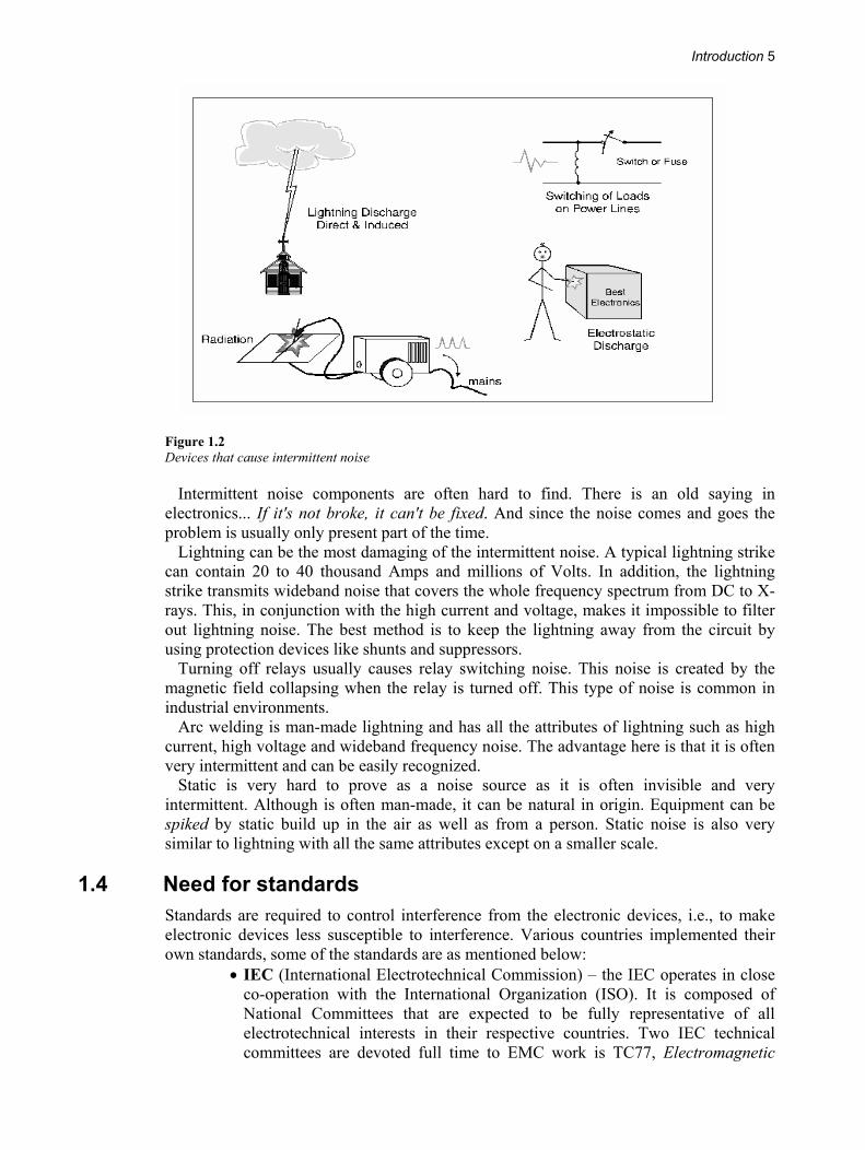
Figure 1.2 Devices that cause intermittent noise
Intermittent noise components are often hard to find. There is an old saying in electronics... If it's not broke, it can't be fixed. And since the noise comes and goes the problem is usually only present part of the time.
Lightning can be the most damaging of the intermittent noise. A typical lightning strike can contain 20 to 40 thousand Amps and millions of Volts. In addition, the lightning strike transmits wideband noise that covers the whole frequency spectrum from DC to X-rays. This, in conjunction with the high current and voltage, makes it impossible to filter out lightning noise. The best method is to keep the lightning away from the circuit by using protection devices like shunts and suppressors.
Turning off relays usually causes relay switching noise. This noise is created by the magnetic field collapsing when the relay is turned off. This type of noise is common in industrial environments.
Arc welding is man-made lightning and has all the attributes of lightning such as high current, high voltage and wideband frequency noise. The advantage here is that it is often very intermittent and can be easily recognized.
Static is very hard to prove as a noise source as it is often invisible and very intermittent. Although is often man-made, it can be natural in origin. Equipment can be spiked by static build up in the air as well as from a person. Static noise is also very similar to lightning with all the same attributes except on a smaller scale.
1.4 Need for standards Standards are required to control interference from the electronic devices, i.e., to make electronic devices less susceptible to interference. Various countries implemented their own standards, some of the standards are as mentioned below:
• IEC (International Electrotechnical Commission) – the IEC operates in close co-operation with the International Organization (ISO). It is composed of National Committees that are expected to be fully representative of all electrotechnical interests in their respective countries. Two IEC technical committees are devoted full time to EMC work is TC77, Electromagnetic
6 Practical Shielding, EMC/EMI, Noise Reduction, Earthing and Circuit Board Layout
compatibility between equipment including networks, and the International Special Committee on Radio Interference or CISPR.
• CENELEC (European Committee for Electrotechnical Standardization) and ETSI (European Telecommunications Standards Institute) – CENELEC is the European standards making body, which has been mandated by the Commission of the EC (European Commission) to produce EMC standards for the use with European EMC Directive. For Telecommunications equipment ETSI is the mandated standards body. ETSI generates standards for telecom network equipment that is not available to the subscriber, and for the radio communications equipment and broadcast transmitters.
Any manufacturer wanting to market his/her goods into a particular country has to
comply with the standards followed by that country.
1.5 EMC – the issues
Figure 1.3 EMC issues
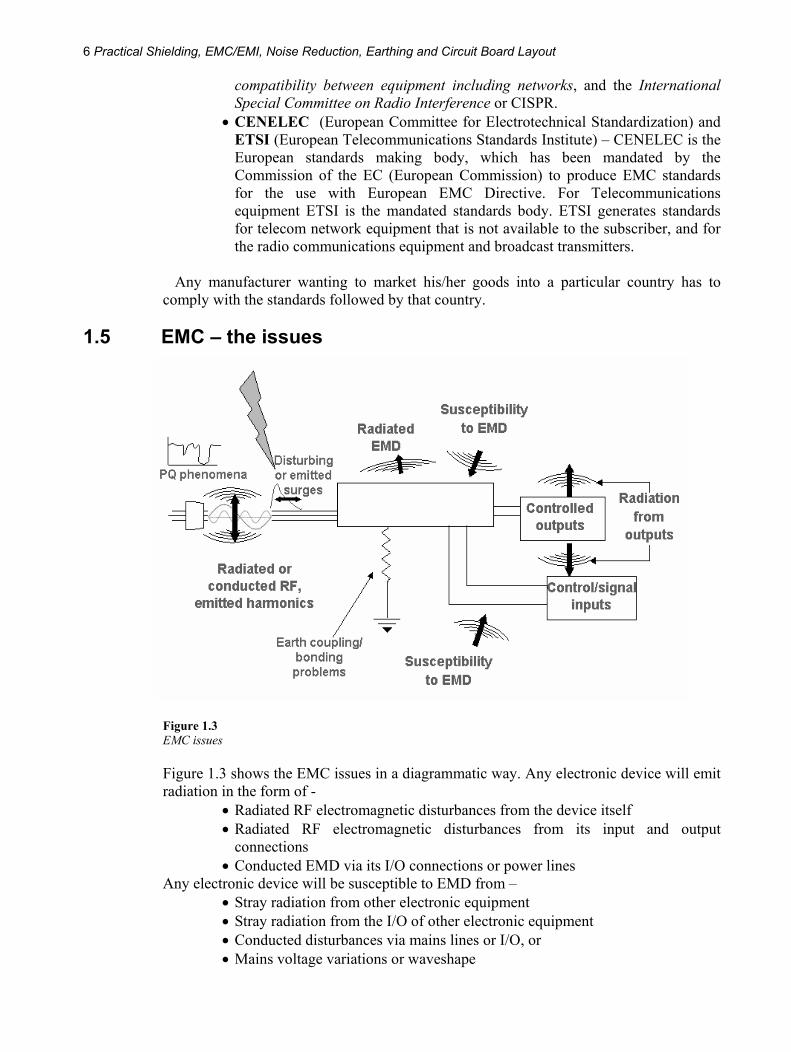
Figure 1.3 shows the EMC issues in a diagrammatic way. Any electronic device will emit radiation in the form of -
• Radiated RF electromagnetic disturbances from the device itself • Radiated RF electromagnetic disturbances from its input and output
connections • Conducted EMD via its I/O connections or power lines
Any electronic device will be susceptible to EMD from – • Stray radiation from other electronic equipment • Stray radiation from the I/O of other electronic equipment • Conducted disturbances via mains lines or I/O, or • Mains voltage variations or waveshape
Introduction 7
1.6 Electromagnetic disturbances Any electromagnetic phenomenon may degrade the performance of the system. Some of the electromagnetic issues are as mentioned below:
• Supply voltage – Mains electricity suffers a variety of disturbing effects during its distribution. These may be caused by sources in the supply network or by other users, or by other loads within the same installation. A pure, uninterrupted supply would not be cost effective; the balance between the cost of the supply and its quality is determined by national regulatory requirements, tempered by the experience of the supply utilities. Typical disturbances are:
# Interruptions
# Dips
# Surges
# Waveform distortion
# Fluctuations
# Voltage imbalance
# Frequency variations
# DC in AC networks
# Power-line carrier signaling
Voltage fluctuations: short-term (sub-second) fluctuations with quite small amplitudes are annoyingly perceptible on electric lightning, though electronic power supply circuits comfortably ignore them. Generation of flicker by high power load switching is subject to regulatory control.
Waveform distortion: at source, the AC mains is generated as a pure sine wave but the reactive impedance of the distribution network together with the harmonic currents drawn by non-linear loads causes voltage distortion. Power converters and electronic power supplies are important contributors to non-linear loading. Harmonic distortion may actually be worse at points remote from the non-linear load because of resonance in the network components. Not only must non-linear harmonic currents be limited but also equipment should be capable of operating with up to 10% total harmonic distortion in the supply waveform.
Voltage variations: the distribution network has finite source impedance and varying loads will affect the terminal voltage. Not including voltage drops within the customer’s premises, an allowance of ±10%, on the nominal voltage will cover normal variations in the UK. The effect of the shift in nominal voltage from 240 V to 230 V, as required by CENELEC Harmonization Document HD 472 S1: 1988 and implemented in the UK by BS 7697: 1993, is that from 1st January 1995 the UK nominal voltage is 230 V with a tolerance of +10%, –6%. After 1st January 2003 the nominal voltage will be 230 V with a tolerance of ±10%, in the line with all other Member States.
8 Practical Shielding, EMC/EMI, Noise Reduction, Earthing and Circuit Board Layout
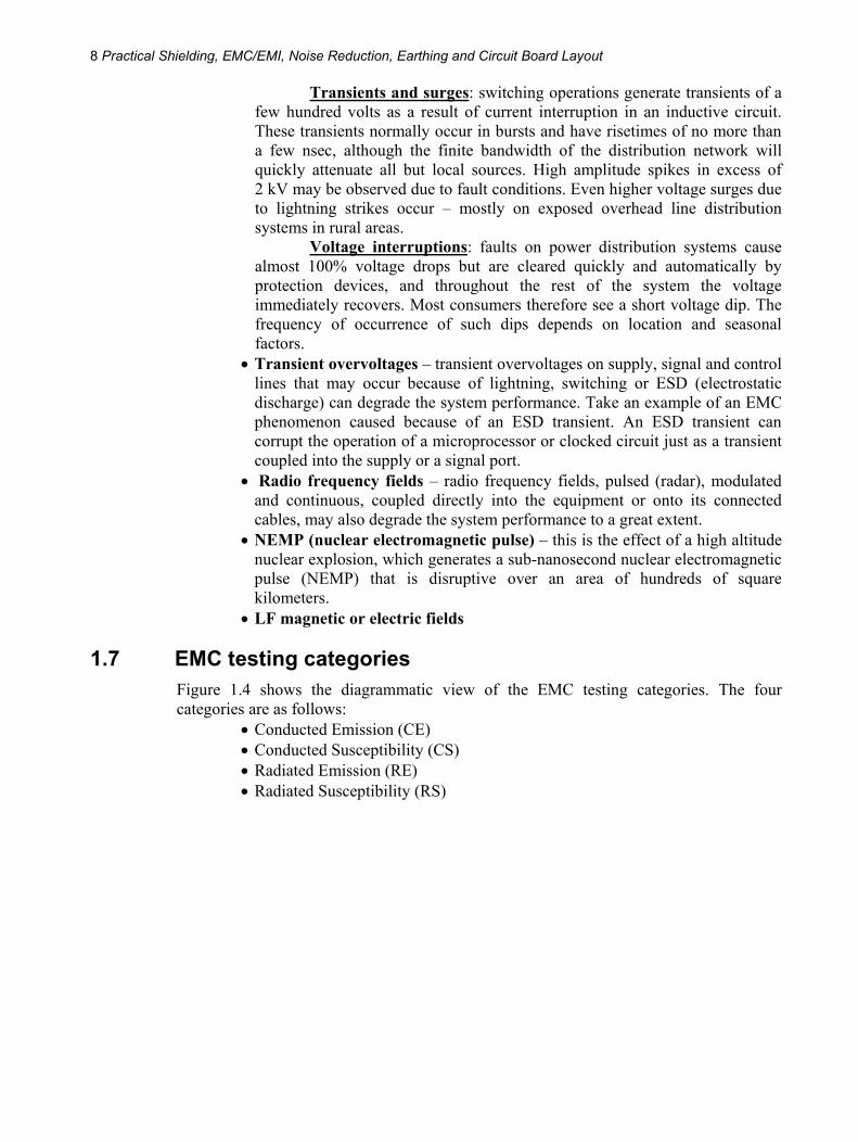
Transients and surges: switching operations generate transients of a few hundred volts as a result of current interruption in an inductive circuit. These transients normally occur in bursts and have risetimes of no more than a few nsec, although the finite bandwidth of the distribution network will quickly attenuate all but local sources. High amplitude spikes in excess of 2 kV may be observed due to fault conditions. Even higher voltage surges due to lightning strikes occur – mostly on exposed overhead line distribution systems in rural areas.
Voltage interruptions: faults on power distribution systems cause almost 100% voltage drops but are cleared quickly and automatically by protection devices, and throughout the rest of the system the voltage immediately recovers. Most consumers therefore see a short voltage dip. The frequency of occurrence of such dips depends on location and seasonal factors.
• Transient overvoltages – transient overvoltages on supply, signal and control lines that may occur because of lightning, switching or ESD (electrostatic discharge) can degrade the system performance. Take an example of an EMC phenomenon caused because of an ESD transient. An ESD transient can corrupt the operation of a microprocessor or clocked circuit just as a transient coupled into the supply or a signal port.
• Radio frequency fields – radio frequency fields, pulsed (radar), modulated and continuous, coupled directly into the equipment or onto its connected cables, may also degrade the system performance to a great extent.
• NEMP (nuclear electromagnetic pulse) – this is the effect of a high altitude nuclear explosion, which generates a sub-nanosecond nuclear electromagnetic pulse (NEMP) that is disruptive over an area of hundreds of square kilometers.
• LF magnetic or electric fields
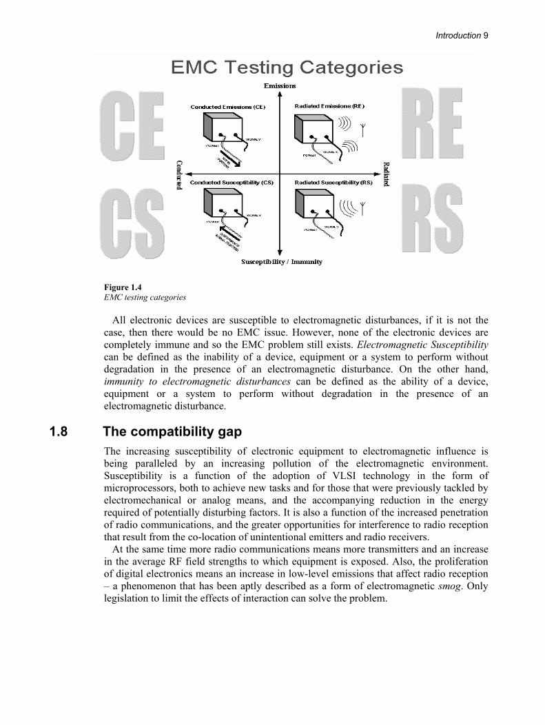
1.7 EMC testing categories Figure 1.4 shows the diagrammatic view of the EMC testing categories. The four categories are as follows:
• Conducted Emission (CE) • Conducted Susceptibility (CS) • Radiated Emission (RE) • Radiated Susceptibility (RS)
Introduction 9
Figure 1.4 EMC testing categories
All electronic devices are susceptible to electromagnetic disturbances, if it is not the case, then there would be no EMC issue. However, none of the electronic devices are completely immune and so the EMC problem still exists. Electromagnetic Susceptibility can be defined as the inability of a device, equipment or a system to perform without degradation in the presence of an electromagnetic disturbance. On the other hand, immunity to electromagnetic disturbances can be defined as the ability of a device, equipment or a system to perform without degradation in the presence of an electromagnetic disturbance.
1.8 The compatibility gap The increasing susceptibility of electronic equipment to electromagnetic influence is being paralleled by an increasing pollution of the electromagnetic environment. Susceptibility is a function of the adoption of VLSI technology in the form of microprocessors, both to achieve new tasks and for those that were previously tackled by electromechanical or analog means, and the accompanying reduction in the energy required of potentially disturbing factors. It is also a function of the increased penetration of radio communications, and the greater opportunities for interference to radio reception that result from the co-location of unintentional emitters and radio receivers.
At the same time more radio communications means more transmitters and an increase in the average RF field strengths to which equipment is exposed. Also, the proliferation of digital electronics means an increase in low-level emissions that affect radio reception – a phenomenon that has been aptly described as a form of electromagnetic smog. Only legislation to limit the effects of interaction can solve the problem.
10 Practical Shielding, EMC/EMI, Noise Reduction, Earthing and Circuit Board Layout
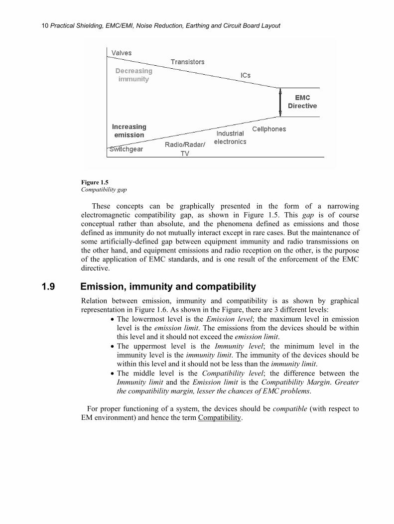
Figure 1.5 Compatibility gap
These concepts can be graphically presented in the form of a narrowing electromagnetic compatibility gap, as shown in Figure 1.5. This gap is of course conceptual rather than absolute, and the phenomena defined as emissions and those defined as immunity do not mutually interact except in rare cases. But the maintenance of some artificially-defined gap between equipment immunity and radio transmissions on the other hand, and equipment emissions and radio reception on the other, is the purpose of the application of EMC standards, and is one result of the enforcement of the EMC directive.
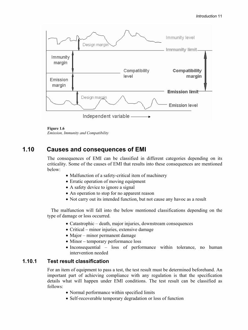
1.9 Emission, immunity and compatibility Relation between emission, immunity and compatibility is as shown by graphical representation in Figure 1.6. As shown in the Figure, there are 3 different levels:
• The lowermost level is the Emission level; the maximum level in emission level is the emission limit. The emissions from the devices should be within this level and it should not exceed the emission limit.
• The uppermost level is the Immunity level; the minimum level in the immunity level is the immunity limit. The immunity of the devices should be within this level and it should not be less than the immunity limit.
• The middle level is the Compatibility level; the difference between the Immunity limit and the Emission limit is the Compatibility Margin. Greater the compatibility margin, lesser the chances of EMC problems.
For proper functioning of a system, the devices should be compatible (with respect to
EM environment) and hence the term Compatibility.
Introduction 11
Figure 1.6 Emission, Immunity and Compatibility
1.10 Causes and consequences of EMI The consequences of EMI can be classified in different categories depending on its criticality. Some of the causes of EMI that results into these consequences are mentioned below:
• Malfunction of a safety-critical item of machinery • Erratic operation of moving equipment • A safety device to ignore a signal • An operation to stop for no apparent reason • Not carry out its intended function, but not cause any havoc as a result
The malfunction will fall into the below mentioned classifications depending on the
type of damage or loss occurred. • Catastrophic – death, major injuries, downstream consequences • Critical – minor injuries, extensive damage • Major – minor permanent damage • Minor – temporary performance loss • Inconsequential – loss of performance within tolerance, no human
intervention needed
1.10.1 Test result classification For an item of equipment to pass a test, the test result must be determined beforehand. An important part of achieving compliance with any regulation is that the specification details what will happen under EMI conditions. The test result can be classified as follows:
• Normal performance within specified limits • Self-recoverable temporary degradation or loss of function
12 Practical Shielding, EMC/EMI, Noise Reduction, Earthing and Circuit Board Layout
• Temporary degradation or loss of function that requires human intervention or system reset
• Degradation or loss of function due to physical damage; software or data corruption
1.11 Levels of compliance and EMC engineering application
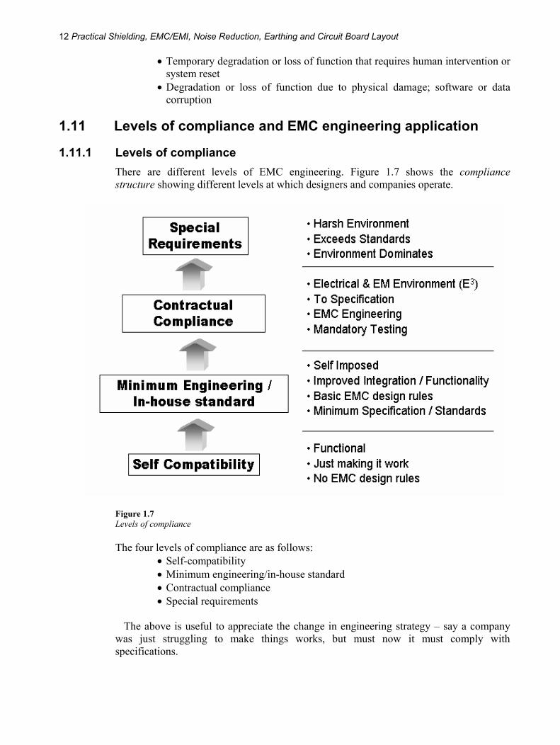
1.11.1 Levels of compliance There are different levels of EMC engineering. Figure 1.7 shows the compliance structure showing different levels at which designers and companies operate.
Figure 1.7 Levels of compliance
The four levels of compliance are as follows: • Self-compatibility • Minimum engineering/in-house standard • Contractual compliance • Special requirements
The above is useful to appreciate the change in engineering strategy – say a company
was just struggling to make things works, but must now it must comply with specifications.
Introduction 13
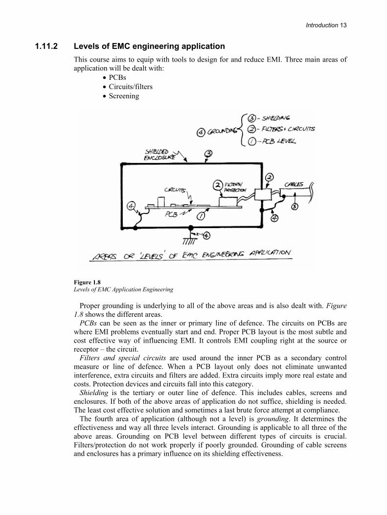
1.11.2 Levels of EMC engineering application This course aims to equip with tools to design for and reduce EMI. Three main areas of application will be dealt with:
• PCBs • Circuits/filters • Screening
Figure 1.8 Levels of EMC Application Engineering
Proper grounding is underlying to all of the above areas and is also dealt with. Figure 1.8 shows the different areas.
PCBs can be seen as the inner or primary line of defence. The circuits on PCBs are where EMI problems eventually start and end. Proper PCB layout is the most subtle and cost effective way of influencing EMI. It controls EMI coupling right at the source or receptor – the circuit.
Filters and special circuits are used around the inner PCB as a secondary control measure or line of defence. When a PCB layout only does not eliminate unwanted interference, extra circuits and filters are added. Extra circuits imply more real estate and costs. Protection devices and circuits fall into this category.
Shielding is the tertiary or outer line of defence. This includes cables, screens and enclosures. If both of the above areas of application do not suffice, shielding is needed. The least cost effective solution and sometimes a last brute force attempt at compliance.
The fourth area of application (although not a level) is grounding. It determines the effectiveness and way all three levels interact. Grounding is applicable to all three of the above areas. Grounding on PCB level between different types of circuits is crucial. Filters/protection do not work properly if poorly grounded. Grounding of cable screens and enclosures has a primary influence on its shielding effectiveness.