Practical Examples - نورپردازی
32
Copyright © Siemens AG 2008. All rights reserved. Sector Energy PTI NC Theodor Connor Practical Examples
Transcript of Practical Examples - نورپردازی

Copyright © Siemens AG 2008. All rights reserved.
Sector Energy PTI NCTheodor Connor
Practical Examples

Page 1 01.2008For internal use only. / Copyright © Siemens AG 2008. All rights reserved.
PTD SE PTITh. Connor
Content
Industrial network
Coal mine supply network
Rural supply network

Page 2 01.2008For internal use only. / Copyright © Siemens AG 2008. All rights reserved.
PTD SE PTITh. Connor
110 kV
6 kV switchgear(with circuit breakers)
0.4 kV busbar
6 kV unit substation (with load interrupter switches and HV fuses)
Performance of Industrial Network improved by Low Resistance Neutral Treatment

Page 3 01.2008For internal use only. / Copyright © Siemens AG 2008. All rights reserved.
PTD SE PTITh. Connor
IC=100A
transient earth fault relay
Initial state (isolated neutral)
unreliable operation of transient earth fault relayshigh overvoltages (transient and power frequent)high fault current over a long time
virtually every earth fault results in multi-pole faulthigh voltage dips in 0.4 kV system in case of multi-pole 6 kV faultman power needed for fault location and switch off

Page 4 01.2008For internal use only. / Copyright © Siemens AG 2008. All rights reserved.
PTD SE PTITh. Connor
Steps of Investigation
Measurements for data acquisitionZero sequence impedance; Reduction factor of cable shieldEarthing and touch Voltages
Calculation of earth fault currents
Comparison of variants of neutral treatmentEffects on operation; Risk of fault propagationDevices for fault detection and protectionNeutral devicesCompliance with touch voltage criteria
Installation of proposed variant of neutral treatmentCommissioning and earth fault test

Page 5 01.2008For internal use only. / Copyright © Siemens AG 2008. All rights reserved.
PTD SE PTITh. Connor
Measurements for data acquisition
ItestCurrent source
A VItest U
6 kV cableNYFG(b)Y
V
remote stationfeeding station
V
measurement of earthingand touch voltages
A Isheath
A Iearth
measurement of earthingand touch voltages
Results:• Z0 1,5 /km + j 1,5 /km
• rE = 0,60 ... 0,80
• UE 20 V/kA
• UB 10 V/kA
Results:• Z0 1,5 /km + j 1,5 /km
• rE = 0,60 ... 0,80
• UE 20 V/kA
• UB 10 V/kA

Page 6 01.2008For internal use only. / Copyright © Siemens AG 2008. All rights reserved.
PTD SE PTITh. Connor
Improved operation with isolated neutral
no interruption of supply no cost for neutral devices
high fault current over a long time risk of multi-pole fault high overvoltages (transient and power frequent) risk of double faultnew capacitive directional earth fault relays necessaryman power needed for fault location and switch off
IC=100A
capacitive earth fault relayIE> = 50 A
Page 7 01.2008For internal use only. / Copyright © Siemens AG 2008. All rights reserved.
PTD SE PTITh. Connor
Operation with earth fault compensation
no interruption of supplysmall earth fault current low risk of multi-pole fault
high overvoltages (transient and power frequent) risk of double faultnew wattmetric earth fault relays and window-type transformers necessaryhigh costs for neutral earthing transformer and arc suppression coil man power needed for fault location and switch off
IRest<10A
wattmetric earth fault relaywindow-type current transformer
ICoil = 140 A

Page 8 01.2008For internal use only. / Copyright © Siemens AG 2008. All rights reserved.
PTD SE PTITh. Connor
Low impedance earthing 2000 A
fast fault clearing low risk of multi-pole faultno transient overvoltages low risk of double faultexisting overcurrent-time relays with phase fault detection can be used
setting of phase fault detection must changed to - smaller starting currents (to detect earth faults) and -higher delay times (to prevent tripping by inrush currents)
voltage dips of up to 10 % in 0.4 kV system in case of 6 kV earth faultsunselective or no tripping of HV fuses
Ik1,max=2kA Ik1,min=0,77kA
overcurrent-time relay(phase fault detection)t» = 0,3 s

Page 9 01.2008For internal use only. / Copyright © Siemens AG 2008. All rights reserved.
PTD SE PTITh. Connor
Low impedance earthing 500 A
fast fault clearing and low fault current low risk of multi-pole faultno transient overvoltages low risk of double faultlow voltage dips in 0.4 kV system in case of 6 kV earth faults
new overcurrent-time relays with earth fault detection necessary
unselective or no tripping of HV fuses
Ik1,max=500AIk1,min=310A
overcurrent-time relay(earth fault detection)IE> = 200A; tE> = 0,3 s

Page 10 01.2008For internal use only. / Copyright © Siemens AG 2008. All rights reserved.
PTD SE PTITh. Connor
Comparison of Investment Costs
Isolatedneutral
Earth fault compensation
Low impedance earthingIk1 = 2000 A
Low impedance earthingIk1 = 500 A
0%
10%
20%
30%
40%
50%
60%
70%
80%
90%
100%cost for protection devices
costs for neutral device

Page 11 01.2008For internal use only. / Copyright © Siemens AG 2008. All rights reserved.
PTD SE PTITh. Connor
Equipment used for low impedance earthing
Neutral earthing transformer
Neutral resistor

Page 12 01.2008For internal use only. / Copyright © Siemens AG 2008. All rights reserved.
PTD SE PTITh. Connor
Results of the short-circuit test
R
6 kV
0,4 kV
voltages 6 kV system
voltages 400 V system
earth fault current

Page 13 01.2008For internal use only. / Copyright © Siemens AG 2008. All rights reserved.
PTD SE PTITh. Connor
Operational experience
low impedance earthing (Ik1 = 500 A) is in operation for more than 2 years
2 earth fault were selectively cleared by protection relays
no unselective tripping in response to earth fault starting
no sensible voltage dips in 0.4 kV system during 6 kV earth faults

Page 14 01.2008For internal use only. / Copyright © Siemens AG 2008. All rights reserved.
PTD SE PTITh. Connor
Adequate neutral treatment for 25kV power supply systems of a new huge open cast lignite mine
Page 15 01.2008For internal use only. / Copyright © Siemens AG 2008. All rights reserved.
PTD SE PTITh. Connor
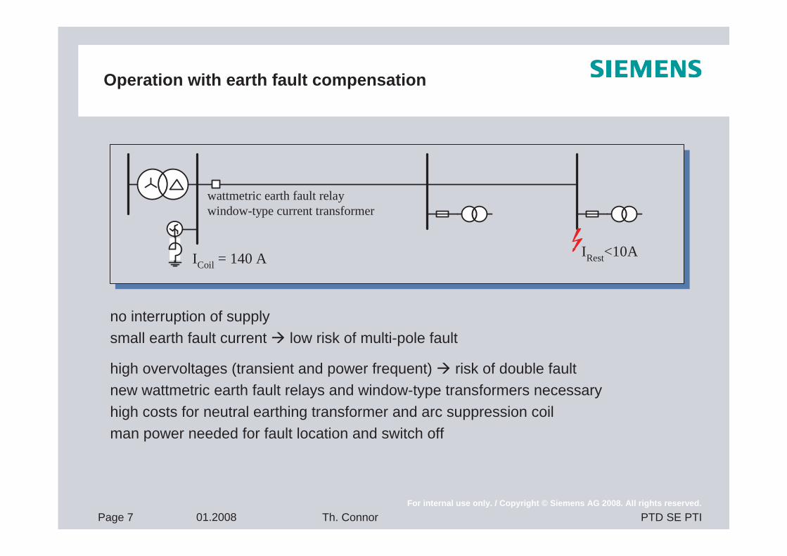
Open cast mine typical equipment
Page 16 01.2008For internal use only. / Copyright © Siemens AG 2008. All rights reserved.
PTD SE PTITh. Connor
Charakteristics of power supply of open castlignite mine
Movement of equipment like stations, transformers, conveyer belts and excavators´ following the work progressHeavy duty conditions due to large mechanical stress, dust, rock, rain, heavy vehiclesMovement of ground due to soil instability in excavation or fill up areasNot all areas are accessible at all time due to work progressReliability requirements regarding permanent output of coal mines due to nearby power stations and maintaining ground water levelFault detection selectivity and speed of fault clearing due to reliability requirements

Page 17 01.2008For internal use only. / Copyright © Siemens AG 2008. All rights reserved.
PTD SE PTITh. Connor
Power supply system of Garzweiler ll
Nine 110kV bays, single bus bar, located at 110/25kV main substation JackerathSix 110/25kV transformers with together 390 MVA, located at 110/25kV substation JackerathEighty 25kV bays, double bus bar, located in the main substation Jackerath165 km of 25kV lines and cables feeding 45 medium voltage transformers (25/6kV) with together 438MVA.The network is operated as radial system equipped with over current protection

Page 18 01.2008For internal use only. / Copyright © Siemens AG 2008. All rights reserved.
PTD SE PTITh. Connor
Parameters for Comparison
Voltage dependent aspectsTransient over voltagesPower frequency over voltages
Current dependent aspectsDamages at fault locationTouch VoltageInductive interferenceThermal stress of equipment
OperationalFault detectionFault locationAmount of switching for re-supply requiredPossibility for automation of operation
InvestmentCost for neutral treatment equipmentCost for protection

Page 19 01.2008For internal use only. / Copyright © Siemens AG 2008. All rights reserved.
PTD SE PTITh. Connor
Measurements for data collection

Page 20 01.2008For internal use only. / Copyright © Siemens AG 2008. All rights reserved.
PTD SE PTITh. Connor
Results of Heavy Current Injection Tests
0
50
100
150
200
250
300
350
1 2 3 4 5 6 7 8 9 10Station
UE a
nd U
T in
V
Ground potential riseTouch voltage
Tolerable touch voltage based on t <0,4s

Page 21 01.2008For internal use only. / Copyright © Siemens AG 2008. All rights reserved.
PTD SE PTITh. Connor
Construction of a Stope Cable

Page 22 01.2008For internal use only. / Copyright © Siemens AG 2008. All rights reserved.
PTD SE PTITh. Connor
Earth fault trails in the new25kV system

Page 23 01.2008For internal use only. / Copyright © Siemens AG 2008. All rights reserved.
PTD SE PTITh. Connor
Preparation of Test Stope Cable
-1500
-1000
-500
0
500
1000
1500
-100 0 100 200 300 400 500 600Time in ms
Cur
rent
L1
in A
Current of faulted phase:

Page 24 01.2008For internal use only. / Copyright © Siemens AG 2008. All rights reserved.
PTD SE PTITh. Connor
Readings of voltages during test
-40
-30
-20
-10
0
10
20
30
40
-100 0 100 200 300 400 500 600Time in ms
Volta
ge L
1 in
kV
-40
-30
-20
-10
0
10
20
30
40
-100 0 100 200 300 400 500 600Time in ms
Volta
ge L
2 in
kV
-40
-30
-20
-10
0
10
20
30
40
-100 0 100 200 300 400 500 600Time in ms
Volta
geL3
in k
V
Voltage of faulted phase Voltages of unfaulted phases
Page 25 01.2008For internal use only. / Copyright © Siemens AG 2008. All rights reserved.
PTD SE PTITh. Connor
Advantages of proposedcurrent limiting neutral earthing
The risk of earth fault developing into cross-country faults is eliminated
Fast and selective tripping of faulty feeder by protection devices
Fast fault location
Possibility of automation of network operation is given
Lowest Costs

Page 26 01.2008For internal use only. / Copyright © Siemens AG 2008. All rights reserved.
PTD SE PTITh. Connor
And it happens!
Uen
Ie
IL1

Page 27 01.2008For internal use only. / Copyright © Siemens AG 2008. All rights reserved.
PTD SE PTITh. Connor
EARTH FAULT TRAILS AND MEASUREMENTS IN RURAL 20 kV NETWORKS
Investigated 20kV network

Page 28 01.2008For internal use only. / Copyright © Siemens AG 2008. All rights reserved.
PTD SE PTITh. Connor
Results of earth fault trials
110 kVnetwork
Earth faultlocation
Feedingsubstation
Measurement ofUL1, UL2, UL3, U0, I0
Measurement ofUL1, UL2, UL3, U0, IL1
Petersen coil
Neutral earthingtransformer
20 kV network
...
Switchingstation
-30
-20
-10
0
10
20
30
-40 -20 0 20 40 60 80 100 120 140 160
t[ms]
UL2
[kV]
-30
-20
-10
0
10
20
30
-40 -20 0 20 40 60 80 100 120 140 160
t[ms]
UL3
[kV]
-30
-20
-10
0
10
20
30
-40 -20 0 20 40 60 80 100 120 140 160
t[ms]
Uen
[kV]
-1500
-1000
-500
0
500
1000
1500
-40 -20 0 20 40 60 80 100 120 140 160
t[ms]
IL1
[A]

Page 29 01.2008For internal use only. / Copyright © Siemens AG 2008. All rights reserved.
PTD SE PTITh. Connor
Harmonic analysis of residual current
-200-150-100-50
050
100150200
200 220 240 260 280 300 320 340 360 380 400
t[ms]
IL1
[A]
0
10
20
30
40
50
60
70
1. 2. 3. 4. 5. 6. 7. 8. 9. 10. 11.
I res
idua
l in
A

Page 30 01.2008For internal use only. / Copyright © Siemens AG 2008. All rights reserved.
PTD SE PTITh. Connor
Results of heavy current injection test
IMessCurrent - source
VIMess U
V
Measurement of Earthelectrode voltage- and
touch voltages
Earthing system ofremote station
Earthing systemof tested station
A
High voltagecable
0
30
60
90
120
150
1 2 3 4 5 6 7 8 9 10 11 12 13 14 15 16 17
Substation
UE
and
UT i
n V
Ground potential riseTouch voltage
Tolerable Touch voltage
0
0,5
1
1,5
2
2,5
NA2XSY
NAKLEY
NEKBA
OHL
Line type
Impe
danc
e in
Zero sequence resistanceZero sequence reactance
Page 31 01.2008For internal use only. / Copyright © Siemens AG 2008. All rights reserved.
PTD SE PTITh. Connor
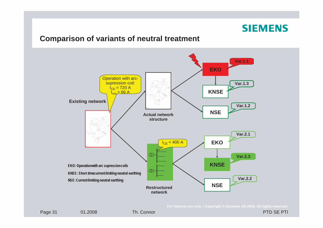
Comparison of variants of neutral treatment
Existing network
Operation with arc-supression coil:
ICE = 720 AIres > 66 A
Actual networkstructure
EKO
KNSE
NSE
Var.1.1
Var.1.3
Var.1.2
Restructurednetwork
ICE < 400 A EKO
KNSE
NSE
Var.2.1
Var.2.3
Var.2.2
EKO: Operation with arc supressioncoils
KNSE: Short time current limiting neutral earthing
NSE: Current limiting neutral earthing