PR9 ES Service Manual - globalis.com · 2.5 information for the operator ... 6.3.9 paper feed motor...
112
PR9 ES Service Manual Ver 1.1 Nantian Electronics Information Corp.,LTD.
Transcript of PR9 ES Service Manual - globalis.com · 2.5 information for the operator ... 6.3.9 paper feed motor...
PR9 ES
Service Manual
Ver 1.1
Nantian Electronics Information Corp.,LTD.

Catalogue 1. PRODUCT OVERVIEW ................................................................. 1
1.1. INTRODUCTION ............................................................... 1
1.2. GENERAL MACHINE CHARACTERISTICS ............................ 1
1.3. SCANNER TECHNICAL DATA ............................................. 3
1.4. DOCUMENTS HANDLED ................................................... 4
1.4.1 PAPER HANDLE INSTITUTION ................................................ 4
1.4.2 CAPACITY OF COPY ............................................................... 4
1.4.3 DOCUMENT HANDLED .......................................................... 4
1.4.4 DOCUMNETS SPECIFICATION AND SHEET THICKNESS DOCUMENTS SPECIFICATION ......................................................... 4
1.5. ACCESSORIES ................................................................... 5
1.6. LOCATING THE PRINTER'S MAJOR COMPONENTS ............ 6
1.7. LOCATING THE PRINTER'S MAJOR INTERNAL COMPONENTS ................................................................................... 8
1.8. GENERAL BLOCK DIAGRAM .............................................. 9
1.9. OPERATING COMMANDS ................................................. 9
1.9.1 POWER SWITCH ............................................................... 9
1.9.2 UPPER MECHANICAL ASSEMBLY LIFTING LEVER ............... 9
1.9.3 LCD OPERATING PANEL.................................................. 10
1.10. LCD PANEL ..................................................................... 10
1.10.1 OPERATING PANEL ................................................. 10
1.10.2 LED Indicators ........................................................ 11
1.10.3 TERMS DEFINITION ................................................. 11
1.10.4 KEYS ....................................................................... 11
1.10.5 LCD: ....................................................................... 12
2. INSTALLATION ........................................................................... 13 2.1 GENERAL INSTALLATION PRECAUTIONS ......................... 13
2.1.1 ELECTRICAL POWER SUPPLY .......................................... 13
2.1.2 ENVIRONMENTAL CONDITIONS ..................................... 13
2.1.3 LOCATING THE MACHINE ............................................... 13
2.2 UNPACKING AND INSTALLING THE MACHINE ................. 14
2.2.1 UNPACKING THE MACHINE ............................................ 14
2.2.2 INSTALLING THE MACHINE ............................................ 15
2.3 OFF-LINE TESTS .............................................................. 15
2.3.1 STARTING AND STOPPING THE PRINT TEST .................... 15
2.3.2 PRINT TEST CONTENTS .................................................. 16
2.4 CONNECTION TO THE SYSTEM ....................................... 18
2.4.1 RS 232C SERIAL INTERFACE (STANDARD) ....................... 18
2.4.2 OPTIONAL SERIAL INTERFACE + USB INTERFACE CARD ... 18
2.4.3 OPTIONAL PARALLEL INTERFACE CARD .......................... 19
2.5 INFORMATION FOR THE OPERATOR .............................. 21
2.6 OPERATING PROCEDURES.............................................. 22
2.6.1 INSERTING A DOCUMENT WITH AUTOMATIC ALIGNMENT 22
2.6.2 INSERTING A PASSBOOK ................................................ 22
2.6.3 EXPULSION OF PROCESSED DOCUMENTS ...................... 23
2.6.4 REPLACING THE RIBBON CARTRIDGE ............................. 23
2.6.5 PAPER JAMS .................................................................. 25
3. OFF-LINE OPERATION, SETUP AND ADJUSTMENT ................. 28 3.1 Overview of off-line operation ....................................... 28
3.2 Classification of off-line operations ................................ 28
3.3 OPERATING PROCESS..................................................... 30
3.3.1 MENU SETUP ................................................................. 30
3.3.2 MENU PRINT ................................................................. 34
3.3.3 PRINTING TEST .............................................................. 37
3.3.4 ADJUSTMENT: ONLY FOR PROFESSIONAL ENGINEER ...... 43
3.3.5 DEBUG/TEST: ................................................................. 50
3.3.6 INQUIRY INFORMATION ................................................ 53
3.3.7 SCANNER’S CIS CALIBRATION ......................................... 53
3.4 PR9 MENU PARAMETERS ............................................... 54
4. FAILURE DIAGNOSE AND PREVENTIVE MAINTENANCE......... 80 4.1 MAINTENANCE .............................................................. 80
4.1.1 FAULT DETECTION ANALYSIS ......................................... 80
4.1.2 ANALYSIS OF THE OPERATING CONDITIONS WORKING ENVIRONMENT: ........................................................................... 80
4.1.3 IDENTIFYING THE MALFUNCTION .................................. 80
4.1.4 FINDING THE CAUSE ...................................................... 80
4.1.5 SOLVING THE PROBLEM ................................................. 81
4.2 FAULT CLASSIFICATION .................................................. 81
4.3 POWER ON FAULTS........................................................ 81
4.4 DOCUMENT PRINTOUT FAULTS ..................................... 82
4.5 DOCUMENT HANDLING FAULTS ..................................... 83
4.6 PREVENTIVE MAINTENANCE .......................................... 84
4.6.1 CLEANING ...................................................................... 84
4.6.2 CLEANING THE CASE ...................................................... 84
4.6.3 CLEANING THE PAPER PATHS ......................................... 84
4.7 LUBRICATION ................................................................. 84
5. MECHANICAL ADJUSTMENTS................................................... 85 5.1 DOCUMENT FEED BELT ADJUSTMENT ............................ 85
5.2 PRINT BAR ADJUSTMENT ............................................... 85
5.3 DISTANCE ADJUSTMENT BETWEEN THE PRINT BAR AND PRINTHEAD NEEDLES ....................................................................... 86
5.4 CARRIAGE MOVMENT BELT ADJUSTMENT ..................... 87
6. DISASSEMBLY/REASSEMBLY THE PRINTER ........................... 88 6.1 DISASSEMBLY/REASSEMBLY INTRODUCE ....................... 88
6.2 ATTENTIONS OF DISASSEMBLY/REASSEMBLY ................. 88
6.3 DISASSEMBLY/REASSEMBLY OF THE MACHINE .............. 88
6.3.1 CASE DISASSEMBLY/REASSEMBLY .................................. 88
6.3.2 DISASSEMBLY/REASSEMBLY the console of liquid crystal Display (LCD) ................................................................................... 89
6.3.3 PHOTOSENSOR BOX DISASSEMBLY/REASSEMBLY .......... 90
6.3.4 MECHANICAL ASSEMBLY DISASSEMBLY/REASSEMBLY ... 90
6.3.5 UPPER PART OF THE MECHANICAL ASSEMBLY DISASSEMBLY/REASSEMBLY............................................................. 91
6.3.6 PRINTHEAD DISASSEMBLY/REASSEMBLY ....................... 92
6.3.7 PRINTHEAD PHOTOSENSOR DISASSEMBLY/REASSEMBLY 92
6.3.8 PRINTHEAD CABLE DISASSEMBLY/REASSEMBLY ............. 92
6.3.9 PAPER FEED MOTOR DISASSEMBLY/REASSEMBLY .......... 93
6.3.10 PRINTHEAD MOVEMENT MOTOR DISASSEMBLY/REASSEMBLY .............................................................. 94
6.3.11 SERVICES MOTOR DISASSEMBLY/ REASSEMBLY ............. 94
6.3.12 PRINTHEAD RESET PHOTOSENSOR DISASSEMBLY/ REASSEMBLY ................................................................................... 95
6.3.13 ROLLER SUPPORT TRAY DISASSEMBLY/REASSEMBLY...... 95
6.3.14 MAIN BOARD DISASSEMBLY/REASSEMBLY ..................... 95
6.3.15 POWER SUPPLY ASSY DISASSEMBLY/REASSEMBLY ......... 96
6.3.16 FEEDER PHOTOSENSORS DISASSEMBLY/REASSEMBLY.... 96
6.3.17 PRINT BAR DISASSEMBLY/REASSEMBLY ......................... 97
6.3.18 ROLLER SUPPORT TRAY(SCANNER) DISASSEMBLY/REASSEMBLY............................................................. 98
6.3.19 UPPER CIS (SCANNER) DISASSEMBLY/REASSEMBLY ........ 98

6.3.20 TRANSMISSION SHAFT(SCANNER) DISASSEMBLY/REASSEMBLY............................................................. 99
6.3.21 LOWER CIS (SCANNER) DISASSEMBLY/REASSEMBLY .... 100
7. APPENDIX ................................................................................ 101 7.1 PR9's FIRMWARE UPDATING OPERATION .................... 101
7.2 PR9 COMMUNICATION CABLE CONNECTION TABLE ..... 106
7.2.1 PR-9T9 COMMUNICATION CABLE TABLE ...................... 106
7.2.2 THE PARALLEL COMMUNICATION CABLE TABLE OF PR9 CONNECT TO THE HOST ............................................................. 107
PR9 Service Manual
Page 1 of 102
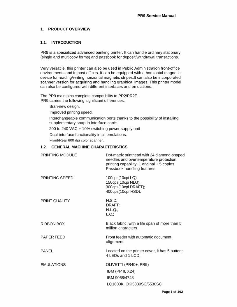
1. PRODUCT OVERVIEW
1.1. INTRODUCTION
PR9 is a specialized advanced banking printer. It can handle ordinary stationary (single and multicopy forms) and passbook for deposit/withdrawal transactions. Very versatile, this printer can also be used in Public Administration front-office environments and in post offices. It can be equipped with a horizontal magnetic device for reading/writing horizontal magnetic stripes.It can also be incorporated scanner version for acquiring and handling graphical images. This printer model can also be configured with different interfaces and emulations.
The PR9 maintains complete compatibility to PR2/PR2E. PR9 carries the following significant differences:
Bran-new design. Improved printing speed. Interchangeable communication ports thanks to the possibility of installing supplementary snap-in interface cards. 200 to 240 VAC + 10% switching power supply unit Dual-interface functionality in all emulations. Front/Rear 600 dpi color scanner.
1.2. GENERAL MACHINE CHARACTERISTICS
PRINTING MODULE
PRINTING SPEED
PRINT QUALITY
RIBBON BOX
Dot-matrix printhead with 24 diamond-shaped needles and overtemperature protection printing capability: 1 original + 5 copies Passbook handling features.
100cps(10cpi LQ); 150cps(10cpi NLG); 300cps(10cpi DRAFT); 400cps(10cpi HSD);
H.S.D; DRAFT; N.L.Q.; L.Q.;
Black fabric, with a life span of more than 5 million characters.
PAPER FEED
PANEL
Front feeder with automatic document alignment.
Located on the printer cover, it has 5 buttons, 4 LEDs and 1 LCD.
EMULATIONS OLIVETTI (PR40+, PR9)
IBM (PP II, X24) IBM 9068/4748 LQ1600K, OKI5330SC/5530SC

PR9 Service Manual
Page 2 of 102
INTERFACE Standard RS 232C serial, optional USB, with the possibility of installing the following interface cards: - 2nd RS 232C serial - Centronics parallel - Centronics parallel + 2nd USB - LAN For Scanner model, the interface is RS 232C serial + USB(on scanner board), the 2nd USB (on main board) is factory option
DIMENSIONS Width: 398 mm;
Depth: 296 mm; Height: 201 mm; Weight: 9 Kg (basic model)
ENVIRONMENTAL CONDITION Temperature:
Operation 5°C ~35°C Storage / Transport -40 °C ~ 50 °C
Relative Humidity: Operation Storage / Transport
15%-85%; ^93% (40 °C)
POWER CONSUMPTION Stand-by: < 5.5W(base model); During operation: 70W, 170 W max
POWER SUPPLY Voltage:: 200 to 240 VAC Frequency: 50HZ + 2%.
+/-10%
The following figure gives an overall view of the printer.

PR9 Service Manual
Page 3 of 102
1.3. SCANNER TECHNICAL DATA
TYPE OF SCANNER Contact
TECHNOLOGY CIS
RESOLUTION 600dpi
ILLUMINATION Set of LEDs
TYPE OF ILLUMINATION RGB
IMAGE ACQUISITION - White / black
- 16 shades of gray
- 256 shades of gray
- RGB(color)
SCANNING WIDTH 216mm
SCANNING FORMAT (W) 80~210 mm
(H) 70~297 mm
PR9 Service Manual
Page 4 of 102
1.4. DOCUMENTS HANDLED
1.4.1 PAPER HANDLE INSTITUTION
Advanced capacity of paper handling: Automatic paper feeding. Adjust the printing thickness automatically. Automatic alignment. Automatic paper edge detection.
1.4.2 CAPACITY OF COPY
Number of copies (carb.) 1+5 (original medium weight: 40g/ [mm]~60g/ [mm], carbon paper weight: 20g /[mm]~40g /[mm]), multicopy carbon paper weight: 380g/mm.
1.4.3 DOCUMENT HANDLED
Single forms, fanfold paper, multicopy paper, passbook, voucher etc.
1.4.4 DOCUMNETS SPECIFICATION AND SHEET THICKNESS DOCUMENTS
SPECIFICATION
-—Single or multicopy carbon paper Width 80mm ~ 245mm Length (OLIVETTI) 70 mm ~ 450mm
Recommended length: 297mm (IBM, OKI, LQ): more than 70mm
Printing field (10 cpi) 238mm
—- Vertical binding passbook Open passbook width 90mm~241.3mm Passbook length 85mm~ 220 mm
-—horizontal binding passbook Passbook width 90mm~ 241.3[mm Open passbook length 85mm~220mm
SHEET THICNESS —single sheet: 0.06mm~0.28mm (45g/mm~160 g/mm) Bind the passbook: only using thread but others, especial staples and clips. Using the passbook: keep the passbook safely and steadily but collapse.
—passbook: Maximum thickness 2mm Max. difference in level between pages 1.2mm (between pages) Cover thickness 0.2mm~0.5mm

PR9 Service Manual
Page 5 of 102
1.5. ACCESSORIES
This section describes the accessories available for the PR9 printer.
BLACK NYLON SNUG CART RIBBON CARTRIDGE Ribbon cartridge specific for the PR9's printhead, with width of 7mm, length of 18m and a life-span of more than 5 million characters The cartridge is installed in the machine by opening the printer cover, with automatic printhead positioning if the printer is powered on or manual positioning if powered off, and lifting the print assembly by using the appropriate green lever.
INDELIBLE NYLON SNUG CART RIBBON CARTRIDGE
Fig. 1-2 PR9 Ribbon Cartridge
PR9 Service Manual
Page 6 of 102
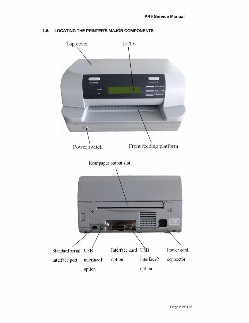
1.6. LOCATING THE PRINTER'S MAJOR COMPONENTS
PR9 Service Manual
Page 7 of 102
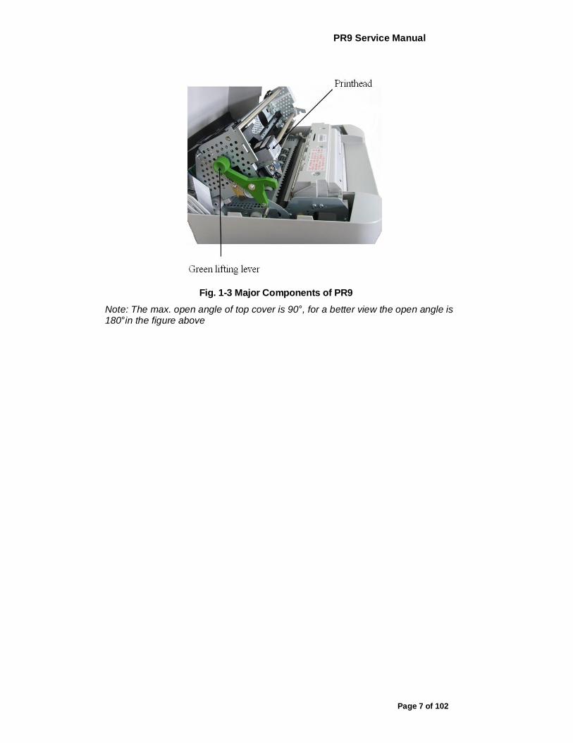
Fig. 1-3 Major Components of PR9
Note: The max. open angle of top cover is 90°, for a better view the open angle is 180°in the figure above
PR9 Service Manual
Page 8 of 102
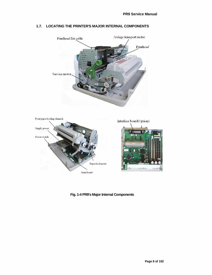
1.7. LOCATING THE PRINTER'S MAJOR INTERNAL COMPONENTS
Fig. 1-4 PR9's Major Internal Components

PR9 Service Manual
Page 9 of 102
1.8. GENERAL BLOCK DIAGRAM
1.9. OPERATING COMMANDS
PR9 operating commands are the following: power switch
- upper mechanical assembly green lifting lever LCD operating panel
1.9.1 POWER SWITCH
The printer is equipped with a two-pole power switch. The switch on/off command is provided by means of a rod that crosses the printer longitudinally.
1.9.2 UPPER MECHANICAL ASSEMBLY LIFTING LEVER
The upper mechanical assembly lifting lever (1) is located on the left-hand side of the printer and is used to lift the upper part of the mechanical assembly so that you can access the internal paper path so that paper jams can be cleared and the ribbon cartridge replaced without needing to power off the printer. To access this lever, lift the printer cover about 45 degrees until it stops.

PR9 Service Manual
Page 10 of 102
Fig. 1-5
Note: The max. open angle of top cover is 90 °, for a better view the open angle is 180 ° in the figure above
1.9.3 LCD OPERATING PANEL
The HMI (Human-machine interface) of the PR9 is mainly consisted of the operating panel (it has 5 keys, 4 LEDS and 160*32 LCD). You can access the different machine states, operating guide and etc. By powering on the printer, you can select and finish a serials of operations including off-line operation, off-line printing, menu setup and so on by pressing key. The PR9 offers more friendly HMI and it make the operation easier and humanization.
1.10. LCD PANEL
1.10.1 OPERATING PANEL
Capacity : Bim(64*256), Chinese character(10CCPL * 2 LINE, 8192 *16*16 Chinese character), character(20CPI * 2LINE , 16*8),User-define content(4*16*16).
PR9 Service Manual
Page 11 of 102
1.10.2 LED Indicators
Led indication in on-line
LED ON OFF BLINK
LED1(0N) POWER ON POWER OFF
LED2(READY) RECEIVING DATA
LED3(STATI0N 1) ASSIGNED USER 1
TO
LED4(STATI0N 2) ASSIGNED USER 2
TO
1.10.3 TERMS DEFINITION
ON-LINE: The statue when power on the printer in normal condition (Top cover is closed and no key is pressed).
STOP MODE: In the on-line mode, pressing |STOP| the printer will enter STOP MODE.
key or opening the cover,
OFF-LINE OPERATION : In the ON-LINE mode, pressing |STATI0N2| and COMPRESSvl keys simultaneously, the printer will enter OFF-LINE MODE/ OPERATION
1.10.4 KEYS
The following table shows the keys' function definitions under different states
The following table shows the keys' function definitions under different states
^^-EiJNCTION ON-LINE STOP MODE OFF-LINE ^ Assign printer to user
1, only be valid under OLIVETTI emulation. ^ Pressing this key and
STATION 1 power on the printer, after the printer resetting, insert A4 sheet, the printer will print PR9 Brief User's Guide
Invalid Invalid
^ Assign printer to user 2, only be valid
under OLIVETTI Skip to upper STATI0N2 emulation. Invalid menu level until
^ Pressing the key and power on the printer, after the
the top level.

PR9 Service Manual
Page 12 of 102
printer resetting, insert A4 siheet, tine printer will print menu configuration
FEED/EJECT ^ If there is fanfold paper in printer, pressing the key, the paper will feed the next page automatically ^ Pressing the key and power on the printer, the printer can ignore the status of cover open
Invalid Menu move backward to the previous item within the same group. It may cycle to the last item from the first one.
STOP Toggles between stop mode and on-line mode.
^ Enter on-line mode under stop mode ^ Invalid under stop mode with cover open
Confirm/accept the selection
COMPRESS Toggles between normal width character and compressed character ,only valid under OKI and LQ emulation
Invalid Move to the next item, return to the first item if current item is the last one .
STATI0N2+C0 MPRESS
pressing these two keys simultaneously, printer will enter the off-line mode
Invalid Pressing these two keys simultaneously, printer will exit off-line mode
STATI0N2+ST0 P
In "Data backup "mode of HEX PRINTING, pressing these two simultaneously, the printer will save the last 8K byte data which it received into flash memory
Invalid Invalid
FEED/EJECT+C OMPRESS
In "Data backup" mode of HEX PRINTING, pressing these two keys simultaneously, the printer will clear all received data which it backs up.
Invalid Invalid
1.10.5 LCD:
LCD can display printer's status and operation indication to make the operation easier.
PR9 Service Manual
Page 13 of 102
2. INSTALLATION
2.1 GENERAL INSTALLATION PRECAUTIONS
To ensure optimal printer functionality and to avoid making service calls for problems that are not directly caused by the product itself, bear in mind the information provided in the following sections.
2.1.1 ELECTRICAL POWER SUPPLY
Make sure that the electrical wall outlet to which the printer is connected has a valid ground and that it is able to supply the power needed by the machine. A wall outlet without ground can cause functional problems and can be a safety hazard.
Do not plug the printer to electrical wall outlets that are already being used by equipment that could cause electrical noise and excessive voltage fluctuations (fans and air conditioners, large photocopiers, lift motors, TV radio transmitters and signal generators, high frequency safety devices, and so on).
Common office equipment (calculating machines, typewriters, terminals and personal computers) can share the same outlet as long as they do not cause excessive electrical noise or voltage fluctuations.
2.1.2 ENVIRONMENTAL CONDITIONS
Environmental temperature: 15 to 35D Relative humidity: 15 to 85%
During machine storage and operation, make sure that condensation does not form as the result of extreme environmental variations. Dust, dirt and smoke can cause the parts in motion to wear excessively, short circuits (in the presence of a high degree of humidity) and read/write errors during operation. High temperatures and low humidity can cause problems due to static electricity.
2.1.3 LOCATING THE MACHINE
The printer must be installed on a flat, vibration-free surface. Do not position the machine near air conditioning systems, heat sources or in direct sunlight. Do not obstruct the printer's ventilation slots. If the printer is installed in a cabinet, make sure that it has good ventilation so as to avoid overheating. Install the printer in a position so that paper jams can be cleared easily.
PR9 Service Manual
Page 14 of 102
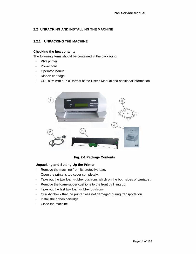
2.2 UNPACKING AND INSTALLING THE MACHINE
2.2.1 UNPACKING THE MACHINE
Checking the box contents The following items should be contained in the packaging:
- PR9 printer - Power cord - Operator Manual - Ribbon cartridge - CD-ROM with a PDF format of the User's Manual and additional information
Fig. 2-1 Package Contents
Unpacking and Setting-Up the Printer - Remove the machine from its protective bag. - Open the printer's top cover completely. - Take out the two foam-rubber cushions which on the both sides of carriage . - Remove the foam-rubber cushions to the front by lifting up. - Take out the last two foam-rubber cushions. - Quickly check that the printer was not damaged during transportation. - Install the ribbon cartridge - Close the machine.

PR9 Service Manual
Page 15 of 102
Fig. 2-2 Removing the Transportation Retainers
2.2.2 INSTALLING THE MACHINE
Position the machine for operation, making sure that it complies with the information provided in section 2.1.
- Make sure that the voltage rating indicated on the electrical data plate corresponds to the local mains. Plug the power cord into the electrical wall outlet (make sure that the printer has been turned off) and then power on the printer.
- Make sure that the printer powers on by checking the mechanical reset and the lighting of the ON LED on the operating panel.
2.3 OFF-LINE TESTS
A print test can be run to make sure that the printer works correctly before actually connecting it to the system.
2.3.1 STARTING AND STOPPING THE PRINT TEST
Proceed as follows to activate the print test:
Power on the printer, after initialization, it will enter the on-line operation
- Pressing down the "STATION 2" and "COMPRESS" keys simultaneously on the console, the printer will enter the off-line operation.
- Pressing COMPRESS key until the LCD shows "MENU PRINTING", pressing STOP key to accept.
PR9 Service Manual
Page 16 of 102
According the LCD's prompting, insert an A4 sheet into the front feed slot until triggering the paper alignment photosensor. The machine will automatically feed the sheet and start printing the test. The sheet is automatically expelled at the end of the test. To repeat the test simply inserts a new of paper. To stop the print test, power off the machine.
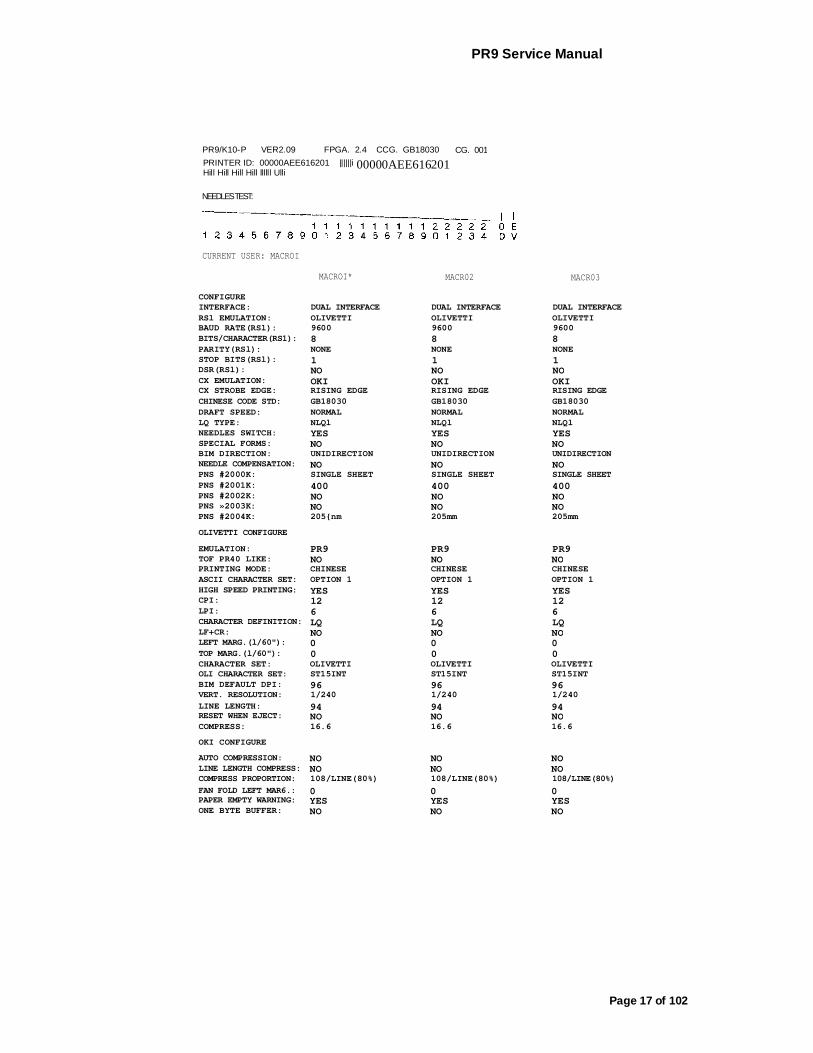
2.3.2 PRINT TEST CONTENTS
The print test provides the following information: - The release and version of the firmware and character generators installed - The ID of the printer - A graphical representation of 24-needle functionality (Needles test) - The configuration of the printer - The current macro. - The parameters defined for the configuration and emulation selected by the
users. The content of the test depends on the FW release and options installed on the printer. The following pages provide examples:
PR9 Service Manual
Page 17 of 102
PR9/K10-P VER2.09 FPGA. 2.4 CCG. GB18030 PRINTER ID: 00000AEE616201 ||||||i Hill Hill Hill Hill llllll Ulli
NEEDLES TEST:
CURRENT USER: MACROI
MACROI* MACR02 MACR03
CONFIGURE INTERFACE: DUAL INTERFACE DUAL INTERFACE DUAL INTERFACE RSl EMULATION: OLIVETTI OLIVETTI OLIVETTI BAUD RATE(RSl): 9600 9600 9600 BITS/CHARACTER(RS1): 8 8 8 PARITY(RSl): NONE NONE NONE STOP BITS(RSl): 1 1 1 DSR(RSl): NO NO NO CX EMULATION: OKI OKI OKI CX STROBE EDGE: RISING EDGE RISING EDGE RISING EDGE CHINESE CODE STD: GB18030 GB18030 GB18030 DRAFT SPEED: NORMAL NORMAL NORMAL LQ TYPE: NLQl NLQl NLQl NEEDLES SWITCH: YES YES YES SPECIAL FORMS: NO NO NO BIM DIRECTION: UNIDIRECTION UNIDIRECTION UNIDIRECTION NEEDLE COMPENSATION: NO NO NO PNS #2000K: SINGLE SHEET SINGLE SHEET SINGLE SHEET PNS #2001K: 400 400 400 PNS #2002K: NO NO NO PNS »2003K: NO NO NO PNS #2004K: 205{nm 205mm 205mm OLIVETTI CONFIGURE EMULATION: PR9 PR9 PR9 TOF PR40 LIKE: NO NO NO PRINTING MODE: CHINESE CHINESE CHINESE ASCII CHARACTER SET: OPTION 1 OPTION 1 OPTION 1 HIGH SPEED PRINTING: YES YES YES CPI: 12 12 12 LPI: 6 6 6 CHARACTER DEFINITION: LQ LQ LQ LF+CR: NO NO NO LEFT MARG.(l/60"): 0 0 0 TOP MARG.(l/60"): 0 0 0 CHARACTER SET: OLIVETTI OLIVETTI OLIVETTI OLI CHARACTER SET: ST15INT ST15INT ST15INT BIM DEFAULT DPI: 96 96 96 VERT. RESOLUTION: 1/240 1/240 1/240 LINE LENGTH: 94 94 94 RESET WHEN EJECT: NO NO NO COMPRESS: 16.6 16.6 16.6 OKI CONFIGURE AUTO COMPRESSION: NO NO NO LINE LENGTH COMPRESS: NO NO NO COMPRESS PROPORTION: 108/LINE(80%) 108/LINE(80%) 108/LINE(80%) FAN FOLD LEFT MAR6.: 0 0 0 PAPER EMPTY WARNING: YES YES YES ONE BYTE BUFFER: NO NO NO
CG. 001 00000AEE616201
PR9 Service Manual
Page 18 of 102
2.4 CONNECTION TO THE SYSTEM
In its basic configuration, the printer is equipped with an on-board standard RS232C interface, the optional interface(s) can be on-board USB and a slot for the installation in field of an optional interface card that connects to the specific connector on the main board. One of the following optional interface cards can be installed in the slot on the rear of the printer: - 2nd RS 232C serial interface card. - Centronics parallel interface card - Centronics parallel + USB interface card - LAN interface card
Active port configuration can be set in menu to be single port, dual-port and triple port configuration so as to satisfy specific application requirements.
2.4.1 RS 232C SERIAL INTERFACE (STANDARD)
Attach the serial cable to the interface located on the rear of the printer.
Via Set-up (Section 3.2) program the following interface parameters: BAUD RATE; BIT/CHAR; PARITY; STOP BIT and DSR.
Fig. 2-3 Standard RS232 C Serial Interface
2.4.2 OPTIONAL SERIAL INTERFACE + USB INTERFACE CARD
The optional serial interface + Universal Serial Bus (USB) interface card hosts both interfaces and is installed in the specific slot alongside the standard first serial interface on the rear of the printer.
PR9 Service Manual
Page 19 of 102
2.4.3 OPTIONAL PARALLEL INTERFACE CARD
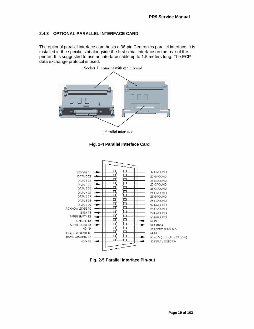
The optional parallel interface card hosts a 36-pin Centronics parallel interface. It is installed in the specific slot alongside the first serial interface on the rear of the printer. It is suggested to use an interface cable up to 1.5 meters long. The ECP data exchange protocol is used.
Fig. 2-4 Parallel Interface Card
Fig. 2-5 Parallel Interface Pin-out
PR9 Service Manual
Page 20 of 102
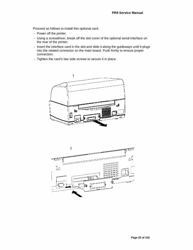
Proceed as follows to install this optional card: - Power off the printer. - Using a screwdriver, break off the slot cover of the optional serial interface on
the rear of the printer. - Insert the interface card in the slot and slide it along the guideways until it plugs
into the related connector on the main board. Push firmly to ensure proper connection.
- Tighten the card's two side screws to secure it in place.

PR9 Service Manual
Page 21 of 102
Fig. 2-6 Installing the parallel interface card
In a printer dual-port configuration consisting of the standard serial interface + parallel interface, in an empty buffer and out of paper condition the printer polls the two ports to see which one will be assigned. When a signal is received by any one of the two interfaces, the printer switches to the receiving interface and maintains this condition until the end of the print job. Dual-port functionality is configured during printer set-up; in particular, active emulation can be set on each of the two interfaces and can be changed in run-time mode by means of a specific command.
2.5 INFORMATION FOR THE OPERATOR
After installation, the field engineer has the responsibility of informing the operator on how to use the printer, how to replace the cartridge and how to clear paper jams. It is suggested that a practical demonstration be given for the following operations:
Using the operating panel, interpreting the error messages and unlocking the machine whenever necessary.
- Inserting a passbook and sheets of paper into the front insertion slot, stressing the importance of avoiding the use of crumpled or torn paper or passbooks with jutting spines. Show how to insert the sheet of paper (automatic alignment) and the savings book (manual alignment). Replacing the ribbon cartridge. Removing a jammed document from the printer by using the lever for lifting the upper mechanical assembly. Inserting a check or tab in the optional check reader, making sure to avoid using documents that are torn, wrinkled, folded or stapled together with paper clips.
- Stress the importance of good internal ventilation and therefore the need to keep the printer vents unobstructed (from forms or other types of paper).

PR9 Service Manual
Page 22 of 102
Make it clear to the operator that observing these simple precautions ensures good printer operation in time. If failures should arise, however, the operator should promptly call the field engineering service.
2.6 OPERATING PROCEDURES
2.6.1 INSERTING A DOCUMENT WITH AUTOMATIC ALIGNMENT
The front shelf on the case helps to insert the document in the printer. - With the printer powered on, place the document at the center of the front slot
and then insert it into the feed slot. Release the document as soon as the automatic alignment system is activated.
Fig. 2-7 Automatic Document Insertion
2.6.2 INSERTING A PASSBOOK
Before inserting a passbook, open it and press it along its spine so that it remains completely open horizontally. Make sure that pages of the book are not folded or ripped so as to prevent a poor print quality and errors during book insertion. Place the open passbook on the front shelf with the magnetic stripe on the bottom.
Fig. 2-7 Manual Insertion of a passbook
PR9 Service Manual
Page 23 of 102
2.6.3 EXPULSION OF PROCESSED DOCUMENTS
The processed documents can be expelled from the printer, according to the application program, in the following ways: - Returning back to where the documents were manually inserted (paper feed
slot) - From the printer's rear slot, starting from the front feed slot
If the documents that are expelled from the front feed slot: - The documents are less than 100mm long, they will be released from the feed
rollers - The documents are 100mm long or longer, they will remain gripped by the last
set of rollers to avoid that the document tails off the front shelf
2.6.4 REPLACING THE RIBBON CARTRIDGE
The ribbon cartridge must be changed when printing is incomplete or faded, or when there are frequent optical read errors on the printed documents. This procedure is to be performed with the machine powered off, if necessary, however, it can even be performed with the machine powered on.
2.6..4.1 TURN OFF PRINTER AND CHANGE THE RIBBON BOX
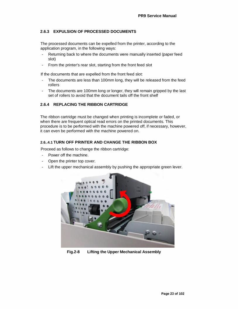
Proceed as follows to change the ribbon cartridge: - Power off the machine. - Open the printer top cover. - Lift the upper mechanical assembly by pushing the appropriate green lever.
Fig.2-8 Lifting the Upper Mechanical Assembly

PR9 Service Manual
Page 24 of 102
Push the ribbon guide downwards, make it withdraw from print head. Take out the used ribbon casket
Fig. 2-9 Remove Ribbon Cartridge
Insert the cartridge into the feed gears, hooking it on the two sides and making sure to insert pin into the related hole of the ribbon feed knob.
Fig. 2-10 Inserting the Ribbon Cartridge
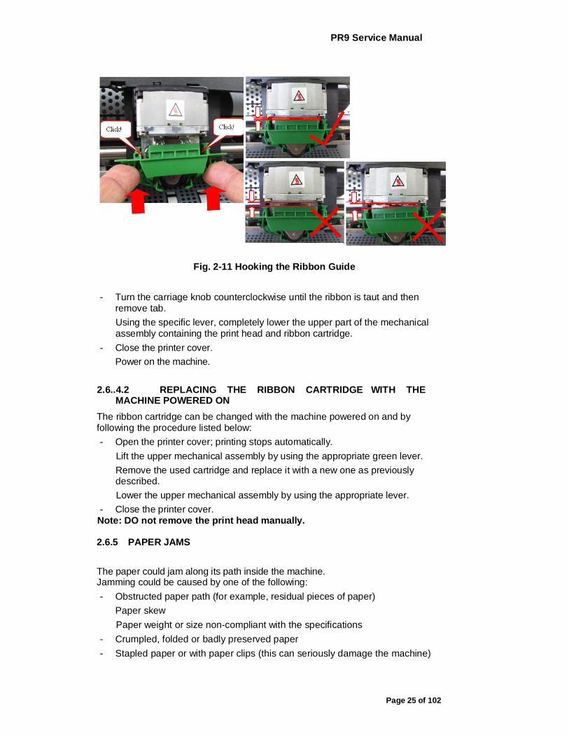
Insert the ribbon guide front wards and then lift it until it hooks on to the two plastic pins on the carriage's open slots behind the print head platen (a "clack" sound is heard).
PR9 Service Manual
Page 25 of 102
Fig. 2-11 Hooking the Ribbon Guide
- Turn the carriage knob counterclockwise until the ribbon is taut and then remove tab. Using the specific lever, completely lower the upper part of the mechanical assembly containing the print head and ribbon cartridge.
- Close the printer cover. Power on the machine.
2.6..4.2 REPLACING THE RIBBON CARTRIDGE WITH THE MACHINE POWERED ON
The ribbon cartridge can be changed with the machine powered on and by following the procedure listed below: - Open the printer cover; printing stops automatically.
Lift the upper mechanical assembly by using the appropriate green lever. Remove the used cartridge and replace it with a new one as previously described. Lower the upper mechanical assembly by using the appropriate lever.
- Close the printer cover. Note: DO not remove the print head manually.
2.6.5 PAPER JAMS
The paper could jam along its path inside the machine. Jamming could be caused by one of the following: - Obstructed paper path (for example, residual pieces of paper)
Paper skew Paper weight or size non-compliant with the specifications
- Crumpled, folded or badly preserved paper - Stapled paper or with paper clips (this can seriously damage the machine)
PR9 Service Manual
Page 26 of 102
- Multi copy forms where the sheets are poorly glued together.
The areas where jams are more likely to occur are: - front document feed slot - inside the printer - rear document output slot
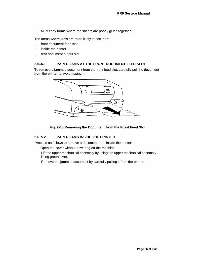
2.6..5.1 PAPER JAMS AT THE FRONT DOCUMENT FEED SLOT To remove a jammed document from the front feed slot, carefully pull the document from the printer to avoid ripping it.
Fig. 2-13 Removing the Document from the Front Feed Slot
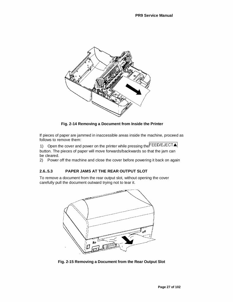
2.6..5.2 PAPER JAMS INSIDE THE PRINTER Proceed as follows to remove a document from inside the printer: - Open the cover without powering off the machine.
Lift the upper mechanical assembly by using the upper mechanical assembly lifting green lever. Remove the jammed document by carefully pulling it from the printer.
PR9 Service Manual
Page 27 of 102
Fig. 2-14 Removing a Document from Inside the Printer
If pieces of paper are jammed in inaccessible areas inside the machine, proceed as follows to remove them: 1) Open the cover and power on the printer while pressing the button. The pieces of paper will move forwards/backwards so that the jam can be cleared. 2) Power off the machine and close the cover before powering it back on again
2.6..5.3 PAPER JAMS AT THE REAR OUTPUT SLOT To remove a document from the rear output slot, without opening the cover carefully pull the document outward trying not to tear it.
Fig. 2-15 Removing a Document from the Rear Output Slot
PR9 Service Manual
Page 28 of 102
3. OFF-LINE OPERATION, SETUP AND ADJUSTMENT
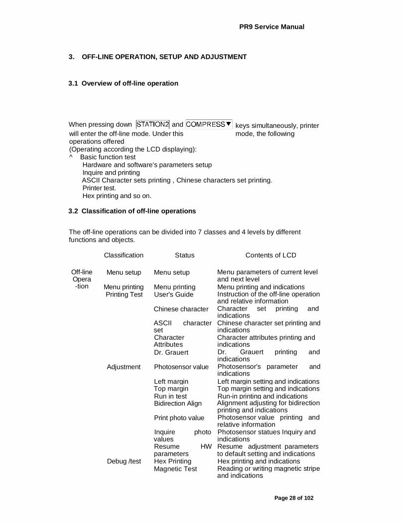
3.1 Overview of off-line operation
keys simultaneously, printer
will enter the off-line mode. Under this mode, the following operations offered (Operating according the LCD displaying): ^ Basic function test
Hardware and software's parameters setup Inquire and printing ASCII Character sets printing , Chinese characters set printing. Printer test. Hex printing and so on.
3.2 Classification of off-line operations
The off-line operations can be divided into 7 classes and 4 levels by different functions and objects.
Classification Status Contents of LCD
Off-line Opera -tion
Menu setup Menu setup Menu parameters of current level and next level
Menu printing Menu printing Menu printing and indications Printing Test User's Guide Instruction of the off-line operation
and relative information Chinese character Character set printing and
indications ASCII character set
Chinese character set printing and indications
Character Attributes
Character attributes printing and indications
Dr. Grauert Dr. Grauert printing and indications
Adjustment Photosensor value Photosensor's parameter and indications
Left margin Left margin setting and indications Top margin Top margin setting and indications Run in test Run-in printing and indications Bidirection Align Alignment adjusting for bidirection
printing and indications Print photo value Photosensor value printing and
relative information Inquire photo values
Photosensor statues Inquiry and indications
Resume HW parameters
Resume adjustment parameters to default setting and indications
Debug /test Hex Printing Hex printing and indications Magnetic Test Reading or writing magnetic stripe
and indications
When pressing down and

PR9 Service Manual
Page 29 of 102
Info inquiry Version FW version, special version tag, extended emulation, version of FPGA, etc.
HW configuration characters generators, optional interface, and other options.
ID ID number
> Menu setup ^ Content: Modify the parameters of the printer configuration, including
each emulation, different macro and different language. ^ Object: All the operators who need to modify the menu parameters, such
as engineer, users and so on.
> Printing menu ^ Content: Printing all menu parameters of various modules; ^ Object: The one who want to get the menu parameters of the printer, including the engineer, users and so on.
> Printing test ^ Content: The printing of User's Guide, ASCII character set, Chinese
character set, character attribute. Dr. Grauert and so on. ^ Object: users and product line
> Adjustment: (Only for Professional) >/
Content: Printing current photosensor parameter, reset photosensor parameters and printing; adjust left margin, top margin and bi-direction printing, run-in printing, inquire photosensor value, reset hardware parameters. The relative printing content refers to appendix. Object: Service engineer and workshop production.
>/
> Debug/Test ^ Content: Hex printing(include: data backup, printing backup data, directly
dump), magnetic stripe operation (include read and write), The relative printing content refer to appendix .
^ Objection: Maintenance and Service engineer
> Inquiry ^ Content: Inquiry the current setting parameters of software or hardware,
including version (FW version, special version tag, special emulation, FPGA Version, etc.), hardware configuration (characters generators, optional interface, scanner, sprocket), printer ID etc.
^ Object: The one who need to get the configuration of printer including engineers, user and so on.

PR9 Service Manual
Page 30 of 102
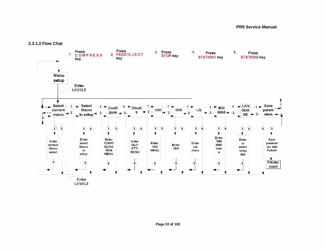
3.3 OPERATING PROCESS
During the Menu Mode the key’s definition is as following: [FEED/EJECT ] upwards; it may cycle to the previous item from the first one.
[COMPRESS ] downwards; it may cycle to the following item from the last one.
[STOP ] accept the selected item or value.
[STATION 2] go back to the previous menu level or back to the top level.
3.3.1 MENU SETUP
Notes:
Menu setup was classified into 10 modules (SELECT CURRENT MACRO, SELECT MACRO TO SETUP, CONFIGURATION, OLIVETTI MENU, OKI MENU, IBM MENU, LQ MENU, IBM9068 MENU, LANGUAGE, SAVE PARAMETERS), modify various module's parameters you should enter corresponding module.
Because the printer can provide different macros selection, you should make sure which macro you want to modify. That means you should enter "Select macro to setup" and select which macro to setup, if not, the modification of set-up you made will be the current macro.
The modified parameters of macro can be valid except the macro is not current macro.

PR9 Service Manual
Page 31 of 102
The operator can select the language condition of printer when entering the module "LANGUAGE", and you can select "CHINESE " or "ENGLISH"
The content the LCD displays on the first line is the current level, and these on the second line is the next level. If you have pressed the key to confirm "save parameter" item , the parameters will be save into the FLASH and the printer will be reset automatically. Otherwise, the parameters will be saved in the RAM, which will not be valid. If restart the printer or exit the off-line operation, all the modification you have made will be invalid.
If modified parameter but not save it, before you exit off-line operation, the LCD will show:
Pressing key to save parameters, other keys will be ignored.
WARNING: All operation should accord the LCD shows.
3.3.1.1 SELECT MODULE
Entering the menu setup, the LCD shows:
You can begin to select module of menu setup
If Pressing key, enter the module "SELECT CURRENT MACRO",
LCD shows:
If pressing key, it will return to the upper level directly, LCD will
show:
If pressing key, enter saving parameter, LCD will show: MENU SETUP SAVE PARAMETERS
If pressing key, saving parameters , LCD will show:
After saving, the printer will reset automatically, and the modified parameters will be saved into the Flash.
If pressing key, the printer will do not save the modified
If Pressing key, LCD shows:

PR9 Service Manual
Page 32 of 102
parameter and it will enter the next item, the LCD will show:
If pressing key, the modified parameter will do not be saved and it will return to the upper item, the LCD will show:
PR9 Service Manual
Page 33 of 102
3.3.1.2 Flow Chat

PR9 Service Manual
Page 34 of 102
3.3.1.3 EXAMPLES For example, we will modify 15CPI of OLIVETTI emulation. After module selected, it will enter the OLIVETTI module, LCD shows:
Pressing key, until the LCD shows: CPI Pressing key, the LCD will shows:
Pressing key, until the LCD shows:
Pressing key, until the LCD shows: CPI
After pressing + key ,the LCD shows: SAVE PARAMETERS
=ACCEPT ST2=IGNORE If you want save the modified parameter into the Flash , pressing key ,the printer will save the modified parameters (into the RAM) and return to the upper level, LCD show: SAVING, PLEASE WAIT After parameters saved, the printer will reset automatically.
3.3.2 MENU PRINT
NOTE: Menu print will print all the macros' menu parameters, the current macro will be remarked by the sign "*". Menu printing just print the configuration and the emulation that selected by current macro. To the interface, PNS and other relative items' parameter, it will remarked by the "—-" to indicate that these items are not selected by the macros except the current macro.
Using shortcut key to print menu: Pressing key and hold it down then power on the printer, after it resets. Insert the A4 sheet, the printer will print current menu parameters.
3.3.2.1 DESCRIPTION
Entering the off-line operation, selecting Menu PRINTING, LCD will show:
Pressing key to accept, LCD shows:

PR9 Service Manual
Page 35 of 102
After the paper inserted, the printer will feed the paper automatically, LCD shows:
After printing finished, the paper will be ejected automatically, LCD shows:
MENU FRETTING FINISH, PRESS STAT2 And now, if you insert A4 sheet again, it will print menu again; if pressing
key, it will exit the Menu printing and enter the sort selection of off-line operation, LCD shows:
Now you can select other operations you want.
The sample of Menu printing:

PR9 Service Manual
Page 36 of 102
PR9/K10-P VER2.09 FPGA. 2.4 CCG. GB18030 PRINTER ID: 00000AEE616201 ||||||i Hill Hill Hill Hill llllll Ulli
NEEDLES TEST:
12 3 4 5 6 1 1
7 8 9 0 1 1111 3 4 5 6
1112 2 2 2 2 7 8 9 0 1 2 3 4
0 E D V
CURRENT USER: MACROI
MACROI* MACR02 MACR03
CG. 001 00000AEE616201

PR9 Service Manual
Page 37 of 102
3.3.3 PRINTING TEST
After entering printing test, LCD shows:
Start to PRINTING TEST item selection.
3.3.3.1 Printing PR9 Brief User's Guide After entering printing test classification, LCD shows:
Pressing key to accept, LCD shows:
After inserting the paper, it will feed the paper automatically, and begin printing, LCD shows:
After finishing printing, the paper will be ejected automatically, LCD shows:
And now, if you insert paper again, the printer will print document again; if pressing STATION 2| key, it will exit the User's Guide printing and enter the item selection of Printing Test, LCD shows:
Now you can select other operations you want.
The sample of printing user's guide:

PR9 Service Manual
Page 38 of 102

PR9 Service Manual
Page 39 of 102
l
3.3.3.2. CHARACTER SET PRINTING
After entering printing test classification, LCD shows:
Pressing key or key until the LCD shows:
Pressing
key to accept, LCD shows:
After inserting the paper, it will feed the paper automatically and begin printing, after finishing printing, the paper will be ejected automatically, LCD shows:
And now, if you insert paper again, the printer will print it again; if you press
key, it will exit the ASCII Character set Printing and enter the item selection
of Printing Test, LCD shows:
Now you can select other operations you want.
The sample of ASCII Character set printing test:

PR9 Service Manual
Page 40 of 102
ASCII CHARACTER SET
PR9 Service Manual
Page 41 of 102
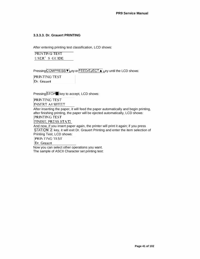
3.3.3.3. Dr. Grauert PRINTING
After entering printing test classification, LCD shows:
Pressing key or key until the LCD shows:
Pressing key to accept, LCD shows:
After inserting the paper, it will feed the paper automatically and begin printing, after finishing printing, the paper will be ejected automatically, LCD shows:
And now, if you insert paper again, the printer will print it again; if you press
key, it will exit Dr. Grauert Printing and enter the item selection of Printing Test, LCD shows:
Now you can select other operations you want. The sample of ASCII Character set printing test:

PR9 Service Manual
Page 42 of 102
Eilzustellung
Norddeutsche Farbenwerke KG Herrn Dr. Grauert Große Elbstraße 64
2000 Hamburg 4
Org. Ill 5/37 H-A 4 34 22.04.75 17.04.75 Volkmann
Vordruckgestaltung für den allgemeinen Schrift- verkehr, für das Bestell- und Rechnungswesen Eilt
Sehr geehrter Herr Dr. Grauert,
Sie können das Schreiben der Briefe, Bestellungen, Rechnungen usw. sowie das Bearbeiten des Schriftguts rationalisieren, wenn die Vordrucke Ihres Unternehmens den folgenden Normen entsprechen:
DIN 676 Geschäftsbrief; Vordrucke A4 DIN 677 -; Vordruck A5 DIN 679 Geschäftspostkarte; Vordrucke A6
DIN 4991 Vordrucke im Lieferantenverkehr; Rechnung DIN 4992 -; Bestellung (Auftrag) DIN 4993 -; Bestellungsannahme (Auftragsbestätigung) DIN 4994 -; Lieferschein/Lieferanzeige DIN 4998 Entwurfsblätter für Vordrucke
Diese Normen enthalten alle Einzelheiten für den sinnvollen und zweckmäßigen Aufdruck. Wenn dazu bei der Beschriftung genormter Vordrucke DIN 5008 "Regeln für Maschinenschreiben" beachtet wird, entstehen übersichtliche und werbewirksame Schriftstücke.
Die beigefügten 6 Mustervordrucke zeigen, daß das Beachten der Normen die künstlerische und werbewirksame Gestaltung der Vor- drucke nicht ausschließt.
Da wir uns auf die Herstellung genormter Vordrucke spezialisiert haben, können wir besonders billig liefern. Eine Probebestellung wird Sie und Ihre Geschäftsfreunde von den Vorteilen überzeugen.
Mit bester Empfehlung
NORAG Druckerei und Verlagshaus KG
Herrmann
Anlagen
6 Mustervordrucke
PR9 Service Manual
Page 43 of 102
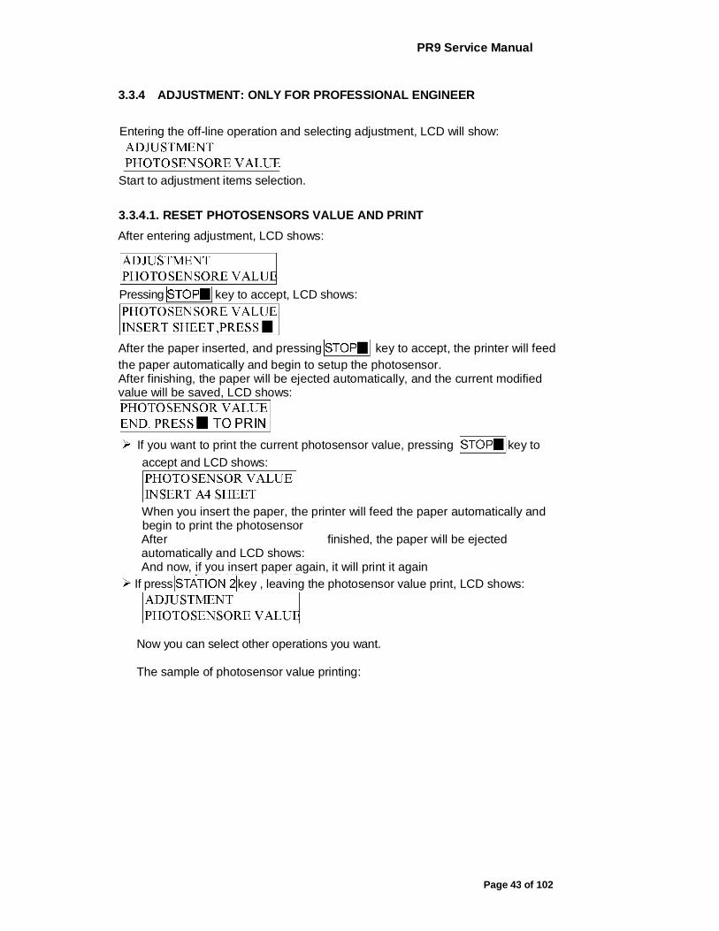
3.3.4 ADJUSTMENT: ONLY FOR PROFESSIONAL ENGINEER
Entering the off-line operation and selecting adjustment, LCD will show:
Start to adjustment items selection.
3.3.4.1. RESET PHOTOSENSORS VALUE AND PRINT
After entering adjustment, LCD shows:
Pressing key to accept, LCD shows:
After the paper inserted, and pressing key to accept, the printer will feed the paper automatically and begin to setup the photosensor. After finishing, the paper will be ejected automatically, and the current modified value will be saved, LCD shows:
If you want to print the current photosensor value, pressing key to
accept and LCD shows:
When you insert the paper, the printer will feed the paper automatically and begin to print the photosensor After finished, the paper will be ejected automatically and LCD shows: And now, if you insert paper again, it will print it again
If press key , leaving the photosensor value print, LCD shows:
Now you can select other operations you want.
The sample of photosensor value printing:
PR9 Service Manual
Page 44 of 102
3.3.4.2. LEFT MARGIN SETUP: NOTE:
Press key means to reduce the current value (moving leftwards), Press key means to increase the current value (moving rightwards)
The value of adjustment is within a range. That is, there is a maximum value to increase and a minimum value to reduce. Entering the adjustment, LCD shows:
Press key or | key until the LCD shows:
Press key to accept, LCD shows:
If you want to see the print effect, insert A4 sheet, the printer will feed the paper automatically, print the current margin and eject the sheet automatically, LCD shows:
Now you can adjust the left margin according your requirement. Press
key means reduce based on current value (moving leftwards). Press key means increase based on the current value (moving
rightwards). If you want to check the print effect. Insert a sheet, it will print it, the LCD show:
After selecting the value you want, you must press key to save, and the printer will exit the left margin setup and enter the classified selection of adjustment, LCD shows:
Now you can select other operations you want.
PR9 Service Manual
Page 45 of 102
3.3.4.3. TOP MARGIN SETUP:
Press key means reduce based on current value (moving upwards) .Press key means increase based on the current value (moving downwards;
The value of adjustment is within a range. That is, there is a maximum value to increase and a minimum value to reduce. Entering the adjustment, LCD shows:
Press I key or key until the LCD shows:
Press key to accept, LCD shows:
If you want to see the print effect, insert A4 sheet, the printer will feed the paper automatically, print the current margin and eject the sheet automatically, LCD shows:
Now you can adjust the top margin according your requirement. Press
key means reduce based on current value (moving upwards). Press key means increase based on the current value (moving
downwards). If you want to check the print effect. Insert a sheet, it will print it, the LCD show:
After selecting the value you want, you must press key to save, and the printer will exit the left margin setup and enter the classified selection of adjustment, LCD shows:
If you press key, it will leave from the top margin setup and enter the Classified selection of adjustment, LCD shows:
Now you can select other operations you want.
3.3.4.4. RUN-IN PRINTING: Once entering the run-in printing, the printer will insert sheet and not stop print automatically from time to time unless you press key or turn off the printer. Entering the adjustment, LCD shows:
PR9 Service Manual
Page 46 of 102
Press key or key until the LCD shows:
Press key to accept, LCD shows:
After inserting the paper, it will feed the paper automatically and the run-in printing start, LCD shows:
(nnn means the times of cover open when run-in printing; mm means the times of run-in printing finished) You just can skip run-in printing by pressing key or turning off the printer. Press key, it will exit the run-in print and enter the classified selection of adjustment, LCD shows: Now you can select other operations you want. The sample of RUN-IN test:
PR9 Service Manual
Page 47 of 102
3.3.4.5. BIDIRECTION ALIGNMENT ADJUSTMENT: You can select different CPI and quality for adjusting in the bidirection alignment print.
Classification : RESULT OF ALL SPEED HSD 10CPI DRAFT 10CPI DRAFT 12CPI HSD 17.1CPI DRAFT 17.1CPI NLQ 10CPI NLQ 12CPI LQ 10CPI
NOTICE : Before adjusting bidirection, you'd better select the "RESULT OF ALL APEED", print all the result of all modes and check it, then do the adjustment according your requirement.
Entering the adjustment, LCD shows:
Press
key or key until the LCD shows:
Press key to accept, LCD shows:
Press key or key until the LCD shows the CPI and
Quality which you want to align, press key to accept, and LCD shows:
If you want to see the print effect, insert A4 sheet, the printer will feed the paper automatically, print the effect and eject the sheet automatically. You can select according your requirement by pressing key (means moving leftwards) and key (means moving rightwards), then you can start to adjust, the LCD will show :
After select the value you want.
Press key to accept, it will be saved , LCD show :
Now you can select other operations you want.
> Press key, it will leave from the bi-direction align printing and enter The classified selection of adjustment, LCD shows :
Now you can select other operations you want.

PR9 Service Manual
Page 48 of 102
NOTICE: Press means reduce based on current value (move
leftwards^. Press key means increase based on the current value (move rightwards)
The adjustment is limited during a range. That is, there is a maximum value to the increase and a minimum to the reduce
The sample of "RESULT OF ALL SPEED" printing:
3.3.4.6. PRINT PHOTOSENSOR VALUES: Entering the adjustment, LCD shows:
Press key or key until the LCD shows:
Press key to accept, LCD shows:
After inserting the paper, the printer will feed the paper automatically. It will print it and eject the sheet automatically, LCD shows:
PR9 Service Manual
Page 49 of 102
Press key, it will exit the photosensor values printing and enter the Classifieds election of adjustment, LCD shows: Now you can select other operations you want. The sample of PRINT PHOTOSENSOR VALUE:
3.3.4.7. INQUIRE PHOTOSENSOR VALUES: NOTICE:
The inquiry of the photosensor can be classified into "FOTO VALUE-SET" and "FOTO VALUE-ACTUAL".
You can inquire 7 class photosensor values : Paper Introl Paper lntro2 Paper Alline 1 PaperAlline2 Paper Alline 3 Paper Alline 4 PAP EDGE
You can check each photosensor's value by pressing key (means move downwards) or key (means upwards)
Entering the adjustment, LCD shows:
Press key or key until the LCD shows:
Press key to accept, LCD shows:
If you want to inquire the photosensor values. Press key to accept, LCD
shows:

PR9 Service Manual
Page 50 of 102
Press key (means move downwards) or key
(means upwards) to check various values .If you want to exit, pressing key , The LCD shows :
Now you can select other operations you want.
3.3.4.8. RESUME HARDWARE PARAMETER: This adjustment mainly used to resume the default value of the following
hardware parameters: Left margin Top margin Bi-direction alignment
Once this item was selected, then the correspondent value will be replaced by the default value and saved into the Flash. Entering the adjustment, LCD shows:
Press key or key until the
LCD shows: Press key to accept, LCD shows:
If you want to resume the hardware parameter. Press key to accept, after finishing resume, LCD shows:
Now you can select other operations you want.
3.3.5 DEBUG/TEST:
Entering the offline-operation, select the Debug-test, the LCD shows:
Start to select the debug/test
3.3.5.1. CLASSFICATION
3.3.5.1.1. HEX printing: can classified into "Data backup", "Printing backup data" and "Directly Dump".
3.3.5.1.2. MAGNEITC TEST: can be classified into "READ MAGNEITC" and "WRITE MAGNEITC".
3.3.5.2. HEX PRINTING

PR9 Service Manual
Page 51 of 102
NOTICE: HEX printing can classified into "Data bacl<up'\ "Printing bacl<up data" and "Directly Dump" "Data backup": The printer can be used for normal operation while all the codes received will be preserved in RAM.
"Printing backup data": After the normal transaction having been treated ,if you need print all saved data in Hex format, entering off-line mode again, and selecting "Printing backup data of HEX printing, put A4 sheet into the printer, all the previously transacted data will be printed in Hex format(NOTE: the first two bytes are the length of the data ), if finished, the printer will enter "Data backup" automatically
> "Direct DUMP": The printer will print all the receiving data in Hex format after A4 sheet in inserted.
NOTE: More sheets are needed if there are too much data. Sheet will be automatically ejected after printing.
Entering the debug/test, LCD shows:
Press key to accept it, LCD shows:
If you want to backup all received codes under the normal operation. Press key to accept it, LCD shows :
During the normal operation, LCD shows the current interface and emulation; After the normal transaction having been treated, if you want to print backup data, entering off-line mode again, select "PRINTING SAVED DATA", LCD shows :
Press key to accept it, LCD shows:
After inserting the paper, the printer will print the data saved in RAM in HEX format, during the process, LCD show:
If the sheet is not long enough, it will be eject automatically. If printing finished, the sheet will be ejected automatically:
Now the printer will enter "Data backup" automatically It can start new data copy in HEX, but it is noticed that the new data will cover the old data every time which was saved last time.
Now , if it is need to print all the receiving data in HEX format. Press key or key until the LCD shows :

PR9 Service Manual
Page 52 of 102
Press key to accept, LCD shows:
After inserting the paper, the printer will print all the receiving data in HEX format, at the same time, LCD show:
If the sheet is not long enough, it will be ejected automatically. If printing finished, the sheet was did not ejected automatically, you have to press
to eject the sheet, LCD shows:
Then, the printer id still in the "Directly DUMP" statue unless the printer is turned off or enter the off-line operation. The sample of HEX printing:
3.3.5.3. MAGNEITC TEST: This test just will be valid when there is the optional magnetic stripes exist.
Entering the debug/test, LCD shows:
Press key or key until the LCD shows:
Press key to accept, LCD shows:
And now, you can select read or write magnetic stripe in different track and BPI

PR9 Service Manual
Page 53 of 102
3.3.6 INQUIRY INFORMATION
Entering the off-line operation, LCD shows:
Then you can start to inquiry.
3.3.6.1. INSTRUCTION
FW VERSION: version, special emulation, (such as: IBM9068, SHINKO, HITACHI etc), special version ID and FPGA version.
HARDWARE CONFIGURE: Chinese character set, horizontal magnetic stripe, USB card, parallel card, SPROCKET, SCANCER etc. D PRINTER ID: there is a unique identify ID for each printer.
EXIT the off-line operation: If you want to exit the off-line operation, pressing down "STATI0N2" and "COMPRESS " keys simultaneously, printer will enter the on-line mode. NOTE:
If selecting "SAVE PARAMETERS" in "MENU SETUP" and confirming, the printer will finish saving and restart
If having entered "ADJUST", when you exit off-line operation, the printer will restart also.
3.3.7 SCANNER’S CIS CALIBRATION
After entering adjustment, LCD shows:
Press to accept, LCD shows:
Because CIS’s width is 216mm,so we need to cut THREE clean A4 sheets(210*297mm)to size of 210*240mm。Align the 3 white sheets to the left side and insert them to the printer (with the long side 240mm forward), printer will feed the sheets automatically and begin calibrating. After about 3 minutes, calibration is finished, the sheets is ejected automatically, LCD shows:
Then you can select other operations. Note: l the scanner’s CIS has been calibrated in factory. Don’t do this calibration unless
needed. l The A4 sheet isn’t the specific module to do scanner calibration, it’s just a
replacement, please make sure the A4 sheets are clean and without any printing.
PR9 Service Manual
Page 54 of 102
3.4 PR9 MENU PARAMETERS
MODULE PARAMETER OPTION EXPLAIN NOTE
CONFIGU RE
RESUME DEFAULT VALUE
NO YES
Select resume default value or not, If select "YES", jump to "SAVE PARAMETERS", the parameters will be resumed the default value if pressing "STOP" to confirm.
This option is mainly used to resume the default value when the menu parameters are be changed in disorder
INTERFACE DUAL INTERFACE SERIAL1 CX
Select interface you want to use
"DUAL'or "CX'will be selected only if optional interface card is installed
RS1 EMULATION
OLIVETTI OKI
IBM LQ1600K IBM9068
SELECT RS1 EMULATION
MODIFY RS1 CONFIG
NO YES
SELECT MODIFY RS1 CONFIGURE OR NOT(BAUD RATE, BITS/CHARACTER, PARITY, STOP BITS, DSR)
BAUD RATE- RS1
2400 4800 9600 19200
Select data send/accept rate for printer's COM2 should be set in state as same as computer's
BITS/CHARAC TER-RS1
8 7
Define the data bit of RS1, it must be accorded with the host's
PARITY-RS1 NONE EVEN ODD
Set the parity type of RS1
PR9 Service Manual
Page 55 of 102
MODULE CONFIGU RE
PARAMETER OPTION EXPLAIN NOTE
STOP BITS - RS1
2 1
Select the stop bits of RS1.
DSR-RS1 NO YES
SERIAL1 handle the DSR signal or not
CX EMULATION
OLIVETTI OKI
IBM LQ1600K IBM9068
Select CX emulation (CX present and it has been selected)
CX STROBE EDGE
FAILING EDGE RISING EDGE
Select the trig mode of the printer strobe signal(CX present and it has been selected)
SB CURRENCY SYMBOL
NO YES
This parameter is effective under Chinese mode
CHINESE CODE STD
GB18030 GBK
GB2312
PNS4003 of PR2E This parameter is effective only under Chinese mode
DRAFT SPEED
NORMAL HIGH SPEED
Select printer speed in draft mode
LQ TYPE NLQ1 NLQ2 LQ2
Select printer type in LQ mode
NEEDLES SWITCH
NO YES
SPECIAL FORMS
NO YES
"YES": Reduce the speed of paper handling, and add some special management to support special forms(e.g. thin paper, paper with different thickness)

PR9 Service Manual
Page 56 of 102
MODULE PARAMETER OPTION EXPLAIN NOTE
CONFIGU RE
BIM DIRECTION
UNDIRECTION BIDIRECTION
Select printing direction for graphics
IGNORE COVER OPEN
NO YES
Ignore cover open or not
This parameter is not effect for English version(alw ays "NO")
NEEDLE COMPENSATI ON
NO YES
Select needle compensation or not when the needle is broken
HIGH SPEED COMPENSATI ON
NO YES
HIGH SPEED COMPENSATION or not
BROKEN NEEDLE NO.
1 2 3 4 5 6 7 8 9 10 11 12 13 14 15 16 17 18 19 20 21 22 23 24
Choose the one needle from 1 to 24 for Compensation
PNS SELECTION
NO YES
PNS selection or not. when selected "YES" , you can select the PNS options as follows
PR9 Service Manual
Page 57 of 102
MODULE PARAMETER OPTION EXPLAIN NOTE
CONFIGU RE
PNS #2000K SINGLE SHEET 205MM 220MM
The selection will influence ejection "205MM": If the paper width exceeds 205MM, OxOC is treated as FORM FEED command; otherwise OxOC is treated as ejecting paper "220MM": If the paper width exceeds 220MM, OxOC is treated as FORM FEED command; otherwise, OxOC is treated as ejecting paper "SINGLE SHEET": OxOC is treated as ejecting paper
PNS4002K of PR2E
PNS#2001 K 200 300 400 500 600 700 800 900 1000
DIGITAL FILTER (CX STB)
PNS #2002K NO YES
reserved
PNS #2003K NO YES
PR9 Service Manual
Page 58 of 102
MODULE PARAMETER OPTION EXPLAIN NOTE
CONFIGU RE
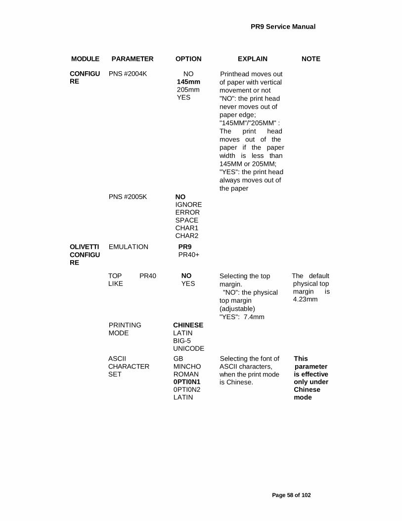
PNS #2004K NO 145mm 205mm YES
Printhead moves out of paper with vertical movement or not "NO": the print head never moves out of paper edge; "145MM"/"205MM" : The print head moves out of the paper if the paper width is less than 145MM or 205MM; "YES": the print head always moves out of the paper
PNS #2005K NO IGNORE ERROR SPACE CHAR1 CHAR2
OLIVETTI CONFIGU RE
EMULATION PR9 PR40+
TOP PR40 LIKE
NO YES
Selecting the top margin. "NO": the physical
top margin (adjustable) "YES": 7.4mm
The default physical top margin is 4.23mm
PRINTING MODE
CHINESE LATIN BIG-5 UNICODE
ASCII CHARACTER SET
GB MINCHO ROMAN 0PTI0N1 0PTI0N2 LATIN
Selecting the font of ASCII characters, when the print mode is Chinese.
This parameter is effective only under Chinese mode
PR9 Service Manual
Page 59 of 102
MODULE OLIVETTI CONFIGU RE
PARAMETER OPTION EXPLAIN NOTE
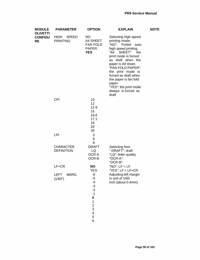
HIGH SPEED PRINTING
NO A4 SHEET FAN FOLD PAPER YES
Selecting high speed printing mode: "NO": Forbid auto high speed printing. "A4 SHEET": the print mode is forced as draft when the paper is A4 sheet. "FAN FOLD PAPER": the print mode is forced as draft when the paper is fan fold paper. "YES": the print mode always is forced as draft
CPI 10 12 12.9 15 16.6 17.1 18 20 30
LPI 5 6 8
CHARACTER DEFINITION
DRAFT LQ
OCR-A OCR-B
Selecting font. " DRAFT": draft "LQ": letter quality "OCR-A": "OCR-B":
LF+CR NO YES
"NO": LF = LF "YES": LF = LF+CR
LEFT MARG. (1/60")
-6 -5 -4 -3 -2 -1 0 1 2 3 4 5 6
Adjusting left margin in unit of 1/60 inch.(about 0.4mm)
PR9 Service Manual
Page 60 of 102
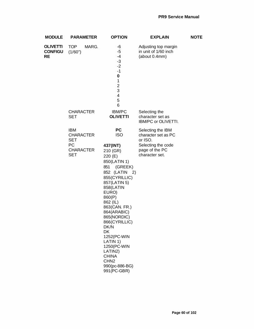
MODULE PARAMETER OPTION EXPLAIN NOTE
OLIVETTI CONFIGU RE
TOP MARG. (1/60")
-6 -5 -4 -3 -2 -1 0 1 2 3 4 5 6
Adjusting top margin in unit of 1/60 inch (about 0.4mm)
CHARACTER SET
IBM/PC OLIVETTI
Selecting the character set as IBM/PC or OLIVETTI.
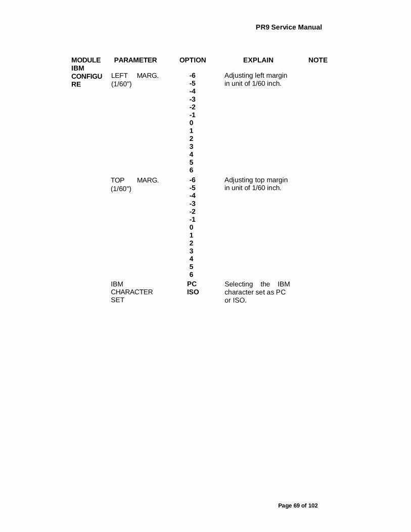
IBM CHARACTER SET
PC ISO
Selecting the IBM character set as PC or ISO.
PC CHARACTER SET
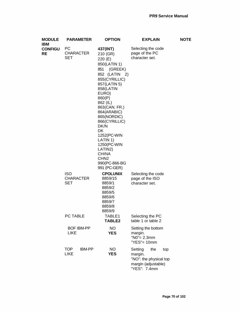
437(INT) 210 (GR) 220 (E) 850(LATIN 1) 851 (GREEK) 852 (LATIN 2) 855(CYRILLIC) 857(LATIN 5) 858(LATIN EURO) 860(P) 862 (IL) 863(CAN. FR.) 864(ARABIC) 865(NORDIC) 866(CYRILLIC) DK/N DK 1252(PC-WIN LATIN 1) 1250(PC-WIN LATIN2) CHINA CHN2 990(pc-886-BG) 991(PC-GBR)
Selecting the code page of the PC character set.
PR9 Service Manual
Page 61 of 102
MODULE PARAMETER OPTION EXPLAIN NOTE
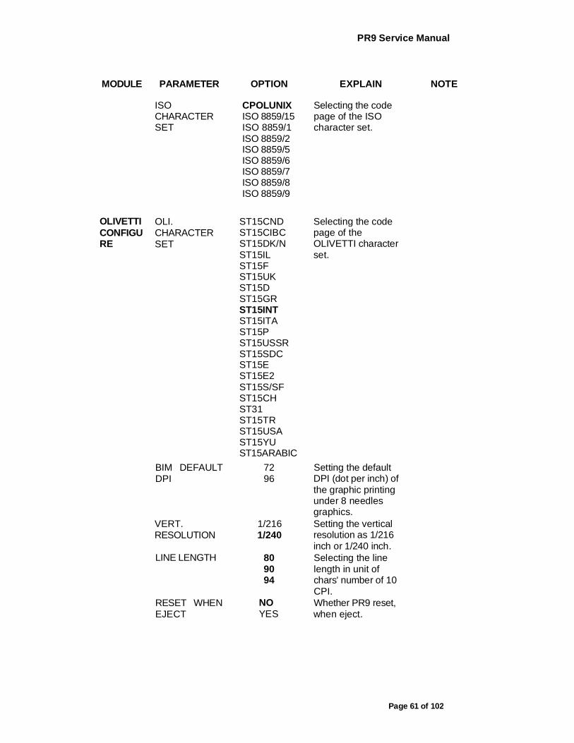
ISO CHARACTER SET
CPOLUNIX ISO 8859/15 ISO 8859/1 ISO 8859/2 ISO 8859/5 ISO 8859/6 ISO 8859/7 ISO 8859/8 ISO 8859/9
Selecting the code page of the ISO character set.
OLIVETTI CONFIGU RE
OLI. CHARACTER SET
ST15CND ST15CIBC ST15DK/N ST15IL ST15F ST15UK ST15D ST15GR ST15INT ST15ITA ST15P ST15USSR ST15SDC ST15E ST15E2 ST15S/SF ST15CH ST31 ST15TR ST15USA ST15YU ST15ARABIC
Selecting the code page of the OLIVETTI character set.
BIM DEFAULT DPI
72 96
Setting the default DPI (dot per inch) of the graphic printing under 8 needles graphics.
VERT. RESOLUTION
1/216 1/240
Setting the vertical resolution as 1/216 inch or 1/240 inch.
LINE LENGTH 80 90 94
Selecting the line length in unit of chars' number of 10 CPI.
RESET WHEN EJECT
NO YES
Whether PR9 reset, when eject.
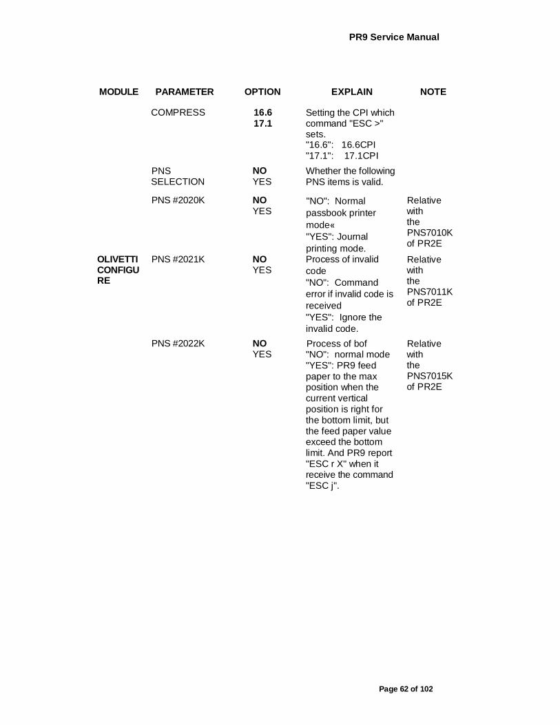
PR9 Service Manual
Page 62 of 102
MODULE PARAMETER OPTION EXPLAIN NOTE
COMPRESS 16.6 17.1
Setting the CPI which command "ESC >" sets. "16.6": 16.6CPI "17.1": 17.1CPI
PNS SELECTION
NO YES
Whether the following PNS items is valid.
PNS #2020K NO YES
"NO": Normal passbook printer mode« "YES": Journal printing mode.
Relative with the PNS7010K of PR2E
OLIVETTI CONFIGU RE
PNS #2021K NO YES
Process of invalid code "NO": Command error if invalid code is received "YES": Ignore the invalid code.
Relative with the PNS7011K of PR2E
PNS #2022K NO YES
Process of bof "NO": normal mode "YES": PR9 feed paper to the max position when the current vertical position is right for the bottom limit, but the feed paper value exceed the bottom limit. And PR9 report "ESC r X" when it receive the command "ESC j".
Relative with the PNS7015K of PR2E

PR9 Service Manual
Page 63 of 102
MODULE PARAMETER OPTION EXPLAIN NOTE
PNS #2023K NO YES
Selecting the special function of the command "ESC ! sp nnn" "NO": same as
PR2, the space setting of the full corner characters is same as half corner characters. "YES": the space setting of the full corner characters is double as half corner characters.
Relative with the PNS7014K of PR2E
PNS #2024K NO YES
"NO": normal mode "YES": ASCII characters printing and the graphic printing in a same line are enabled.
Relative with the PNS7016K of PR2E
PNS #2025K NO YES
PNS #2026K NO YES
STANDARD DIN/ISO ANSI
IBM3604 IBM4746 IS07811 HT-2751-C1Z IS08484
Selecting the magnetic record standard.
It is used for PR9/K V1.07 T9 and later version.
DUPLICATE NO YES
Selecting the magnetic record is duplicate.
It is used for PR9/K V1.07 T9 and later version.
END SENTINEL
C F
Selecting the end sentinel of the magnetic record.
It is used for PR9/K V1.07 T9 and later version.

PR9 Service Manual
Page 64 of 102
MODULE
OPTION
HOR.
MSRW.
PARAMETER OPTION EXPLAIN NOTE
DISPLACEMEN T
STANDARD +10 +20
Selecting the position displacement of magnetic record.
It is used for PR9/K V1.07 T9 and later version.
POSITION ADJUST
-7 -6 -5 -4 -3 -2 -1 0 1 2 3 4 5 6 7
Selecting the adjust value for the position of magnetic record when read magnetic stripe.
It is used for PR9/K V1.07 T9 and later version.
RETRY 1 3 5
Selecting the retry number for reading magnetic stripe.
It is used for PR9/K V1.07 T9 and later version.
STRIPE HANDLE
NORMAL FAST
Selecting stripe handle mode. "NORMAL": measure the width of passbook when read magnetic stripe every time. "FAST": measure the width of passbook only one time, next time using the width.
It is used for PR9/K V1.07 T9 and later version.
AUTO COMPRESSIO N
NO YES
Determine whether automatically condense current line for printing, when current line length exceed the allowed line length.
LINE LENGTH COMPRESS
NO YES
Determine whether to compress by line width
PR9 Service Manual
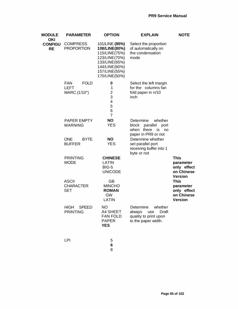
Page 65 of 102
MODULE OKI
CONFIGU RE
PARAMETER OPTION EXPLAIN NOTE
COMPRESS PROPORTION
101/LINE (85%) 108/LINE(80%) 115/LINE(75%) 123/LINE(70%) 133/LINE(65%) 144/LINE(60%) 157/LINE(55%) 170/LINE(50%)
Select the proportion of automatically on the condensation mode
FAN FOLD LEFT MARC.(1/10")
0 1 2 3 4 5 6 7
Select the left margin for the columns fan fold paper in n/10 inch
PAPER EMPTY WARNING
NO YES
Determine whether block parallel port when there is no paper in PR9 or not
ONE BYTE BUFFER
NO YES
Determine whether set parallel port receiving buffer into 1 byte or not
PRINTING MODE
CHINESE LATIN BIG-5 UNICODE
This parameter only effect on Chinese Version
ASCII CHARACTER SET
GB MINCHO ROMAN GW
LATIN
This parameter only effect on Chinese Version
HIGH SPEED PRINTING
NO A4 SHEET FAN FOLD PAPER YES
Determine whether always use Draft quality to print upon to the paper width.
LPI 5 6 8

PR9 Service Manual
Page 66 of 102
MODULE OKI CONFIGU RE
PARAMETER OPTION EXPLAIN NOTE
CHARACTER DEFINITIONS
DRAFT LQ
Select default character quality
LF+CR NO YES
"No": LF=LF "YES": LF=LF+CR
CR+LF NO YES
"No": CR=CR "YES": CR=CR+LF
LEFT MARC. (1/60")
-6 -5 -4 -3 -2 -1 0 1 2 3 4 5 6
Aadjust left margin in unit of 1/60 inch
TOP MARG. (1/6")
-1 0 1 2 3 4 5 6
Adjust top margin in unit of 1/6 inch
TOP MARG (1/60")
-5 -4 -3 -2 -1 0 1 2 3 4 5
Adjust top margin in unit of 1/60 inch
LINE LENGTH 80 90 94
Set line length in unit of characters number of 10CPI
RESET WHEN EJECT
NO YES
PR9 Service Manual
Page 67 of 102
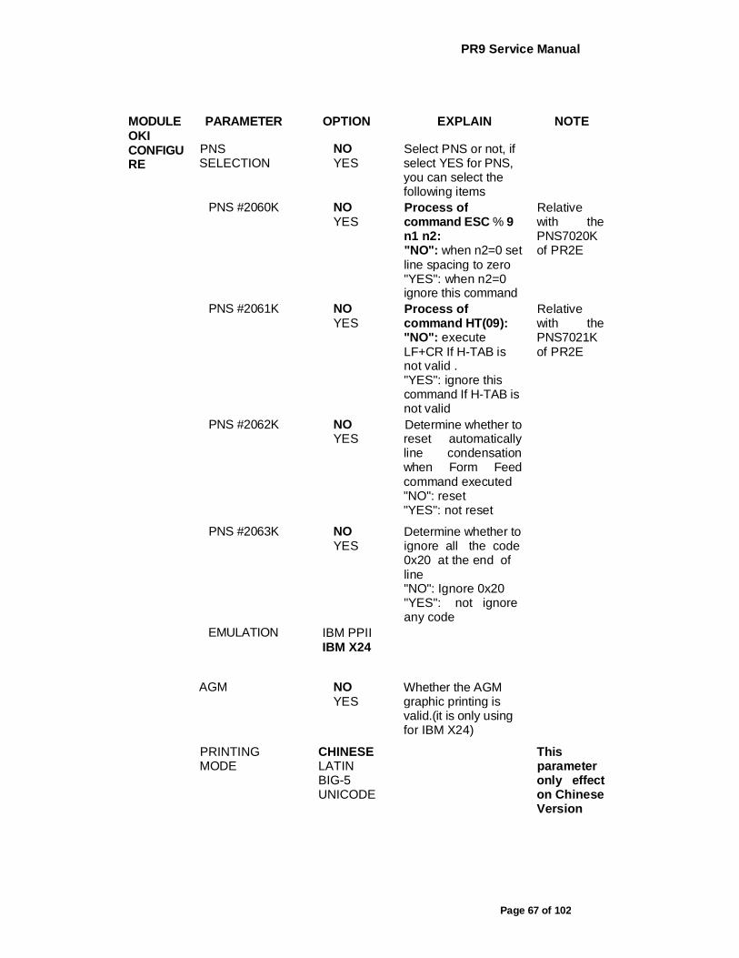
MODULE OKI CONFIGU RE
PARAMETER OPTION EXPLAIN NOTE
PNS SELECTION
NO YES
Select PNS or not, if select YES for PNS, you can select the following items
PNS #2060K NO YES
Process of command ESC % 9 n1 n2: "NO": when n2=0 set line spacing to zero "YES": when n2=0 ignore this command
Relative with the PNS7020K of PR2E
PNS #2061K NO YES
Process of command HT(09): "NO": execute LF+CR If H-TAB is not valid . "YES": ignore this command If H-TAB is not valid
Relative with the PNS7021K of PR2E
PNS #2062K NO YES
Determine whether to reset automatically line condensation when Form Feed command executed "NO": reset "YES": not reset
PNS #2063K NO YES
Determine whether to ignore all the code 0x20 at the end of line "NO": Ignore 0x20 "YES": not ignore any code
EMULATION IBM PPII IBM X24
AGM NO YES
Whether the AGM graphic printing is valid.(it is only using for IBM X24)
PRINTING MODE
CHINESE LATIN BIG-5 UNICODE
This parameter only effect on Chinese Version
PR9 Service Manual
Page 68 of 102
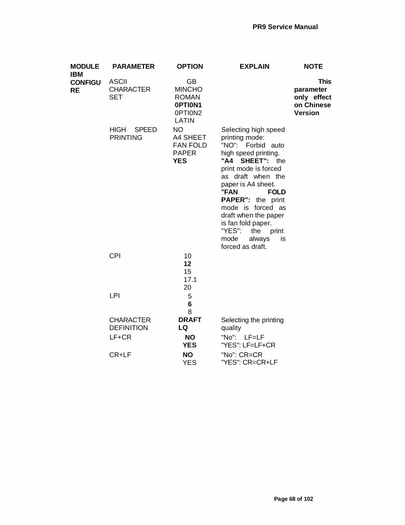
MODULE IBM CONFIGU RE
PARAMETER OPTION EXPLAIN NOTE
ASCII CHARACTER SET
GB MINCHO ROMAN 0PTI0N1 0PTI0N2 LATIN
This parameter only effect on Chinese Version
HIGH SPEED PRINTING
NO A4 SHEET FAN FOLD PAPER YES
Selecting high speed printing mode: "NO": Forbid auto high speed printing. "A4 SHEET": the print mode is forced as draft when the paper is A4 sheet. "FAN FOLD PAPER": the print mode is forced as draft when the paper is fan fold paper. "YES": the print mode always is forced as draft.
CPI 10 12 15 17.1 20
LPI 5 6 8
CHARACTER DEFINITION
DRAFT LQ
Selecting the printing quality
LF+CR NO YES
"No": LF=LF "YES": LF=LF+CR
CR+LF NO YES
"No": CR=CR "YES": CR=CR+LF
PR9 Service Manual
Page 69 of 102
MODULE IBM CONFIGU RE
PARAMETER OPTION EXPLAIN NOTE
LEFT MARG. (1/60")
-6 -5 -4 -3 -2 -1 0 1 2 3 4 5 6
Adjusting left margin in unit of 1/60 inch.
TOP MARG. (1/60")
-6 -5 -4 -3 -2 -1 0 1 2 3 4 5 6
Adjusting top margin in unit of 1/60 inch.
IBM CHARACTER SET
PC ISO
Selecting the IBM character set as PC or ISO.
PR9 Service Manual
Page 70 of 102
MODULE IBM CONFIGU RE
PARAMETER OPTION EXPLAIN NOTE
PC CHARACTER SET
437(INT) 210 (GR) 220 (E) 850(LATIN 1) 851 (GREEK) 852 (LATIN 2) 855(CYRILLIC) 857(LATIN 5) 858(LATIN EURO) 860(P) 862 (IL) 863(CAN. FR.) 864(ARABIC) 865(NORDIC) 866(CYRILLIC) DK/N DK 1252(PC-WIN LATIN 1) 1250(PC-WIN LATIN2) CHINA CHN2 990(PC-866-BG 991 (PC-GER)
Selecting the code page of the PC character set.
ISO CHARACTER SET
CPOLUNIX 8859/15 8859/1 8859/2 8859/5 8859/6 8859/7 8859/8 8859/9
Selecting the code page of the ISO character set.
PC TABLE TABLE1 TABLE2
Selecting the PC table 1 or table 2
BOF IBM-PP LIKE
NO YES
Setting the bottom margin. "N0"= 2.3mm "YES"= 10mm
TOP IBM-PP LIKE
NO YES
Setting the top margin. "NO": the physical top margin (adjustable) "YES": 7.4mm

PR9 Service Manual
Page 71 of 102
MODULE IBM CONFIGU RE 1
PARAMETER OPTION EXPLAIN NOTE
ZERO S1_ASH NO YES
Determines the printout of '0' (0x30) "YES": '0' will be printed with a slash on it
LINE LENGTH 80 90 94
Setting the line length in unit of character of 10CPI.
INSERET IVIODE
DIRECT PR2 LIKE
Selecting the insert mode. "DIRECT": PR9 insert paper directly when paper alignment. "PR2 LIKE": PR9 insert paper when printing data is received, it is same as PR2.
PAGE LENGTH 11 12
Setting the page length in unit of inch
RESET WHEN EJECT
NO YES
Whether PR9 reset, when eject.
COIVIPRESS 16.6 17.1
Setting CPI which command "SI" set. "16.6": 16.6CPI "17.1": 17.1CPI
PNS SELECTION
NO YES
Whether the following PNS items is valid.
PNS #2080K NO YES
"NO": Double height printing and bold printing are valid in any print pitch. "YES": The print pitch is forced to 10 CPI or 12 CPI when Double height printing or bold printing.
Relative the PNS4001K of PR2E
PNS #2081K NO YES
This parameter only effect on Chinese Version

PR9 Service Manual
Page 72 of 102
MODULE PARAMETER OPTION EXPLAIN NOTE
LQ CONFIGU RE
AUTO COMPRESSIO N
NO YES
Determine whether automatically condense current line for printing, when current line length in fact is exceed the allowed line length.
LINE LENGTH COMPRESS
NO YES
Determine whether the proportion of automatically line condensation is upon to the current line length or it is fixed by menu
COMPRESSIO N PROPORTION
101/LINE (85%) 108/LINE (80%) 115/LINE
(75%) 123/LINE
(70%) 133/LINE
(65%) 144/LINE
(60%) 157/LINE
(55%) 170/LINE (50%)
Select the proportion of automatically line condensation
FAN FOLD LEFT MARC.(1/10")
0 1 2 3 4 5 6 7
Select the left margin for the 80 columns fan fold paper in n/10 inch
PAPER EMPTY WARNING
NO YES
Determine whether block parallel port when there is no paper in PR9 or not
PRINTING MODE
CHINESE LATIN BIG-5 UNICODE
This parameter only effect on Chinese Version
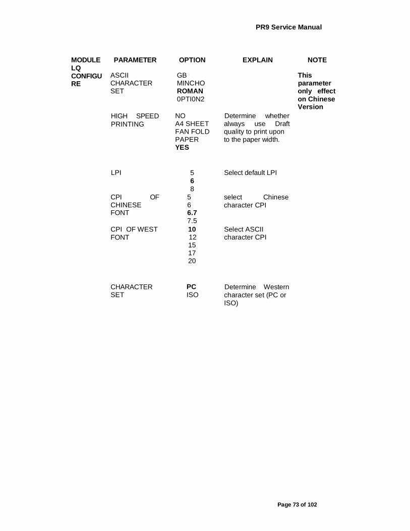
PR9 Service Manual
Page 73 of 102
MODULE LQ CONFIGU RE
PARAMETER OPTION EXPLAIN NOTE
ASCII CHARACTER SET
GB MINCHO ROMAN 0PTI0N2
This parameter only effect on Chinese Version
HIGH SPEED PRINTING
NO A4 SHEET FAN FOLD PAPER YES
Determine whether always use Draft quality to print upon to the paper width.
LPI 5 6 8
Select default LPI
CPI OF CHINESE FONT
5 6 6.7 7.5
select Chinese character CPI
CPI OF WEST FONT
10 12 15 17 20
Select ASCII character CPI
CHARACTER SET
PC ISO
Determine Western character set (PC or ISO)

PR9 Service Manual
Page 74 of 102
MODULE LQ CONFIGU RE
PARAMETER OPTION EXPLAIN NOTE
PC CHARACTER SET
437(INT) 210 (GR) 220 (E) 850(LATIN 1) 851 (GREEK) 852 (LATIN 2) 855(CYRILLIC) 857(LATIN 5) 858(LATIN EURO) 860(P) 862 (IL) 863(CAN. FR.) 864(ARABIC) 865(NORDIC) 866(CYRILLIC) DK/N DK 1252(PC-WIN LATIN 1) 1250(PC-WIN LATIN2) CHINA CHN2 990(PC-866-BG
) 991 (PC-GER)
select PC character set
ISO CHARACTER SET
CPOLUNIX 8859/15 8859/1 8859/2 8859/5 8859/6 8859/7 8859/8 8859/9
Select ISO character set
CHARACTER DEFINITION
DRAFT LQ
Select default character quality
LF+CR NO YES
"No": LF=LF "YES": LF=LF+CR
CR+LF NO YES
"No": CR=CR "YES": CR=CR+LF

PR9 Service Manual
Page 75 of 102
MODULE LQ CONFIGU RE
PARAMETER OPTION EXPLAIN NOTE
LEFT MARG.(1/60")
-6 -5 -4 -3 -2 -1 0 1 2 3 4 5 6
Left margin adjust in n/60inch
TOP MARG. (1/6")
-1 0 1 2 3 4 5 6
Top margin adjust in n/6inch
TOP MARG MICRO-ADJUS TMENT. (1/60")
-5 -4 -3 -2 -1 0 1 2 3 4 5
Top margin adjust in n/60inch
ZERO SLASH NO YES
Determines if O's (zeros) are crossed out with "/"s (slash) when they are printed
LINE LENGTH 80 90 94
Select 10CPI characters per line
RESET WHEN EJECT
NO YES
Determine whether reset character attribute after paper eject
PNS SELECTION
NO YES
Determine whether make PNS valid
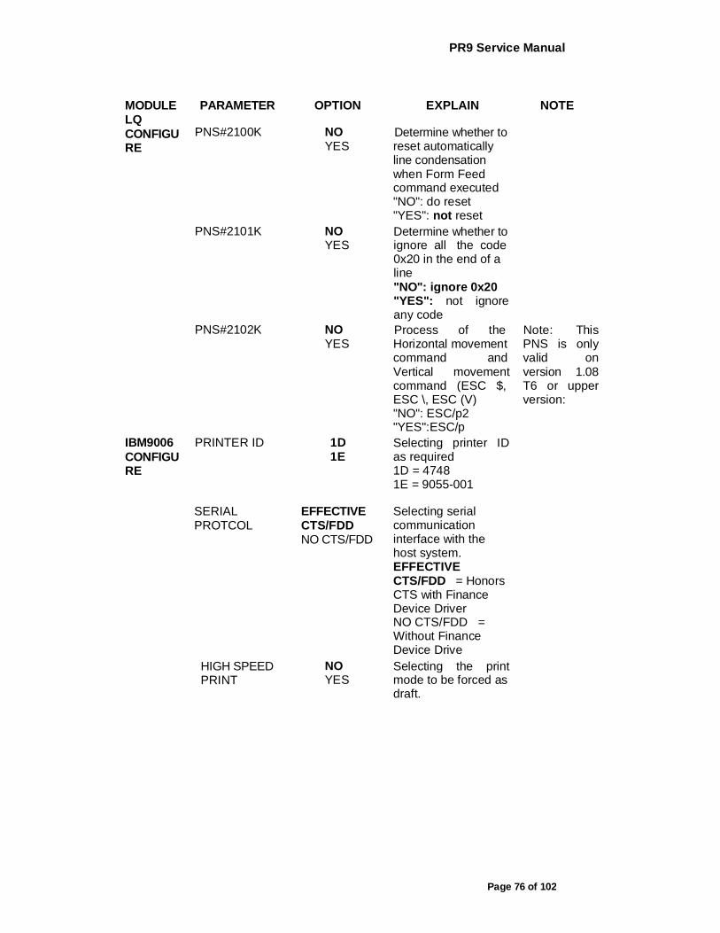
PR9 Service Manual
Page 76 of 102
MODULE LQ CONFIGU RE
PARAMETER OPTION EXPLAIN NOTE
PNS#2100K NO YES
Determine whether to reset automatically line condensation when Form Feed command executed "NO": do reset "YES": not reset
PNS#2101K NO YES
Determine whether to ignore all the code 0x20 in the end of a line "NO": ignore 0x20 "YES": not ignore any code
PNS#2102K NO YES
Process of the Horizontal movement command and Vertical movement command (ESC $, ESC \, ESC (V) "NO": ESC/p2 "YES":ESC/p
Note: This PNS is only valid on version 1.08 T6 or upper version:
IBM9006 CONFIGU RE
PRINTER ID 1D 1E
Selecting printer ID as required 1D = 4748 1E = 9055-001
SERIAL PROTCOL
EFFECTIVE CTS/FDD NO CTS/FDD
Selecting serial communication interface with the host system. EFFECTIVE CTS/FDD = Honors CTS with Finance Device Driver NO CTS/FDD = Without Finance Device Drive
HIGH SPEED PRINT
NO YES
Selecting the print mode to be forced as draft.
PR9 Service Manual
Page 77 of 102
MODULE PARAMETER OPTION EXPLAIN NOTE
-6 -5
-4 -3 -2
LEFT MARG -1 Adjust left margin in (1/60") 0
1 2 3 4 5 6
unit of 1/60 inch (about 0.4mm)
-6 -5
-4 -3 -2
negative value to
TOP MARG (1/60")
-1 0
Adjust top margin in unit of 1/60 inch
decrease top ,and
1 (about 0.4mm) positive 2
3 4 5 6
value to increase top
-10 -9
-8 -7 -6
IBM9006 -5 -4
CONFIGU RE
BOF ADJUST (0.5mm)
-3 -2 -1 0 1 2 3 4 5 6 7 8 9 10
Adjust the BOF margin in unit of 0.5mm

PR9 Service Manual
Page 78 of 102
MODULE IBM9006 CONFIGU RE
PARAMETER OPTION EXPLAIN NOTE
FEED ADJUST(1mm/ 10")
-10 -9 -8 -7 -6 -5 -4 -3 -2 -1 0 1 2 3 4 5
The adjustment when the form feed lOinch, 0.5mm/inch
The item is not valid now.
LPI 5 6 8
UNIDIRECTIO N
EFFICIENCY IGNORE
Set command to set UNIDIRECTION is valid or not
LF+CR NO YES
"No": LF=LF "YES": LF=LF+CR
CR+LF NO YES
"No": CR=CR "YES": CR=CR+LF
COUNTRY CODE PAGE
GIG-5 UNICODE IBM-PC GB18030
GBK GB2312
This parameter only effect on Chinese Version
CPI OF COMPRESS
17.1 18
17.1 = 17.1CPI in condensed mode 18= 18CPI in condensed mode
CPI 10 12 15
The printing character numbers per inch
LINE LENGTH 82.5 94
Select line length in unit of characters number of 10CPI
RESET WHEN EJECT
NO YES
Whether PR9 reset, when eject.
IGNORE ERROR
NO YES
"NO": invalid code results in error "YES": ignore the invalid code.

PR9 Service Manual
Page 79 of 102
MODULE PARAMETER OPTION EXPLAIN NOTE
BEEP WARNING
BEEP ON BEEP OFF
Determines if the alarm sounds when an end of document is detected.
PNS SELECTION
NO YES
Whether the following PNS items is valid.
PNS#2120K NO YES
"NO": Normal bottom margin limit. "YES": Special bottom margin limit.
PR9 Service Manual
Page 80 of 102
4. FAILURE DIAGNOSE AND PREVENTIVE MAINTENANCE
4.1 MAINTENANCE
The following describes maintenance method for field engineers.
4.1.1 FAULT DETECTION ANALYSIS
The user who detected product malfunction can give information regarding the operating mode the printer was in when the malfunction occurred and the related error indications that were provided. The repetition of the fault, when possible, can help with its identification. For fault diagnosis purposes, it is important to establish whether the fault is repetitive or random.
4.1.2 ANALYSIS OF THE OPERATING CONDITIONS
WORKING ENVIRONMENT:
- An environment that is too cold, hot or humid could be the cause of certain malfunctions. The machine must not be positioned near air conditioning system vents or exposed to direct sun light. Make sure that the machine's internal ventilation slots are not blocked, especially if the printer is installed in furniture.
- Forms, documents or office equipment located. - Make sure that the accessories installed in the machine are originals and in
good condition. - Check that the documents inserted in the printer comply with the machine
specifications and are in good condition.
PRINTER OPERATING CONDITIONL: - Check that the internal parts of the machine have no dirt deposited or residue
of paper or ink that could interfere with the performance of the printer's different components.
- Make sure there is no internal damage caused by the insertion of documents with metal clips, staples, and pins or similar.
- Ensure that the parts specified are correctly lubricated.
4.1.3 IDENTIFYING THE MALFUNCTION
- Carefully examine all the information collected (from the Operator, printer error signals, analysis of the documents where the fault has occurred, repetition of the error when the machine is powered on, etc.) to recognize and identify the machine malfunction to be corrected.
- At times a malfunction is generated by more than one cause: it is important in such cases to isolate the faults and deal with them one at a time.
4.1.4 FINDING THE CAUSE
Using experience together with the information given in this section as a guide, take a logical path to find the fault, starting from the most probable cause through, to the most possibility until malfunction part is found.

PR9 Service Manual
Page 81 of 102
4.1.5 SOLVING THE PROBLEM
Repair the machine so that it correctly resumes to operating as normal.
4.2 FAULT CLASSIFICATION
To make the search easier, the faults have been classified as follows: - 4.3 Power-on faults - 4.4 Document printout faults - 4.5 Document handling faults
Each fault classification lists the more probable failures and their possible causes. The classification provided in this chapter cannot cover all the faults that could occur on the machine: if the fault detected is not described herein, refer to the description of a similar fault.
4.3 POWER ON FAULTS
Note: Incorrect set-up X

PR9 Service Manual
Page 82 of 102
4.4 DOCUMENT PRINTOUT FAULTS

PR9 Service Manual
Page 83 of 102
4.5 DOCUMENT HANDLING FAULTS

PR9 Service Manual
Page 84 of 102
4.6 PREVENTIVE MAINTENANCE
4.6.1 CLEANING
For a correct printer operation, it is suggested that the internal components of the machine be cleaned periodically and whenever the machine is serviced.
4.6.2 CLEANING THE CASE
Power off the machine, unplug it from the electrical outlet and then clean its case using a damp cloth; avoid using corrosive substances such as solvents, alcohol solutions, petrol or abrasive components.
4.6.3 CLEANING THE PAPER PATHS
Clean all the document paths including the paper feed rollers of the front paper feeder, making sure to remove any paper or ribbon residues that are deposited on the parts. Also remove any foreign matter.
4.7 LUBRICATION
Although machine lubrication is not scheduled throughout its entire life span, during each service call you are expected to check the lubrication of the different parts by referring to the lubrication points table indicated below.
DESCRIPTION GREASE OIL Printhead carriage slide shafts X Carriage felt X Ribbon feed gear X reed support pin X Hole of the contact bushing between roller shaft and strap shaft
X
Center pressure device in shaft contact area X Bushings in the shaft contact area X Services Motor X Services Motor gear X Pulley toothing X Ribbon feed rotation pin hole with support pin X Belt tightener pin with return pulley X Rubber in the damper assembly hole X Print crosspiece in the following areas X Pin contact left bracket X Guide hole center pin X Inside the crosspiece adjustment screw holes X

PR9 Service Manual
Page 85 of 102
5. MECHANICAL ADJUSTMENTS
The mechanical adjustments have been divided into: - MACHINE CONDITION: Describes the condition that the printer must be in in
order to be able to perform a successful adjustment. - OBJECTIVE ADJUSTMENT: Indicates the points, values and tolerances to
be observed to ensure good kinematic operation. PROCEDURE: Describes the operations to be performed for the adjustment. Notes: Indicates any reference to adjustment sequences or to tests to be performed once the adjustment is made.
5.1 DOCUMENT FEED BELT ADJUSTMENT
MACHINE CONDITION: Unimportant. OBJECTIVE ADJUSTMENT: The tension of timing belt (1) must sag 2.9 + 2mm when applying 200 gr + 10gr at the center of the lower span. PROCEDURE: Loosen the motor securing nuts (2), tighten the belt accordingly and then tighten nuts (2) again.
Fig. 5-1
5.2 PRINT BAR ADJUSTMENT
MACHINE CONDITION: Power off the machine and lift the front part of mechanical assembly. PROCEDURE: While holding the printhead carriage on the axis make sure it vertical justification to the screw (2), adjust screw (2) until the printhead photosensor wheel edge approach to the print bar gently. Repeat this procedure on the other screw located on the opposite side of the frame.
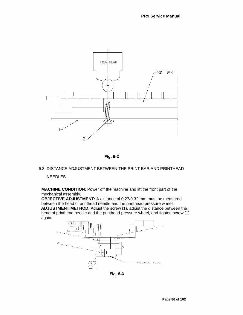
PR9 Service Manual
Page 86 of 102
5.3 DISTANCE ADJUSTMENT BETWEEN THE PRINT BAR AND PRINTHEAD
NEEDLES
MACHINE CONDITION: Power off the machine and lift the front part of the mechanical assembly. OBJECTIVE ADJUSTMENT: A distance of 0.27/0.32 mm must be measured between the head of printhead needle and the printhead pressure wheel. ADJUSTMENT METHOD: Adjust the screw (1), adjust the distance between the head of printhead needle and the printhead pressure wheel, and tighten screw (1) again.
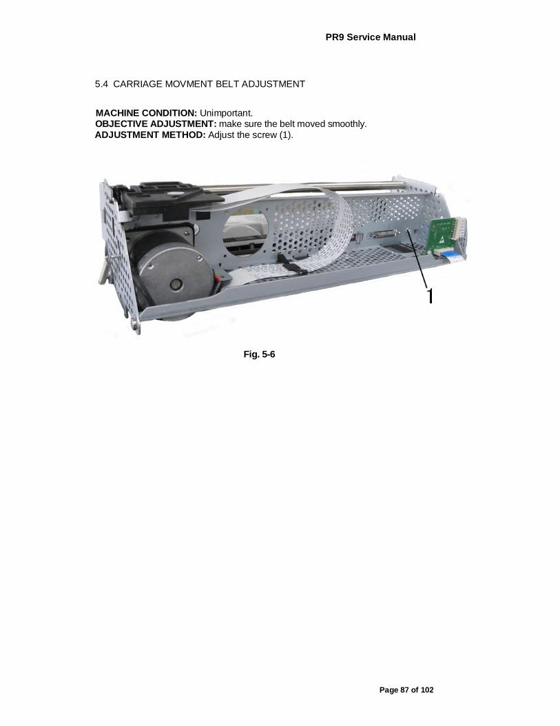
PR9 Service Manual
Page 87 of 102
5.4 CARRIAGE MOVMENT BELT ADJUSTMENT
MACHINE CONDITION: Unimportant. OBJECTIVE ADJUSTMENT: make sure the belt moved smoothly. ADJUSTMENT METHOD: Adjust the screw (1).
Fig. 5-6
PR9 Service Manual
Page 88 of 102
6. DISASSEMBLY/REASSEMBLY THE PRINTER
6.1 DISASSEMBLY/REASSEMBLY INTRODUCE
Disassembly/reassembly procedure: Described the sequence of the disassembly. Notes: recall adjustments that need to be made after reassembly, precautions or warnings to be observed.
6.2 ATTENTIONS OF DISASSEMBLY/REASSEMBLY
- To ensure maximum safety, before starting any disassembly operation power off the printer and unplug its power cord from the electrical outlet.
- All operations should be performed in a clean and uncluttered area. - Follow the procedures carefully; do not unscrew parts that are not to be disassembled.
- Store the disassembled parts in a clean place where there is no danger of them getting lost.
- After replacing the parts, make sure that they have not been deformed during assembly; restore the correct conditions if necessary. Reassembly must be performed by following the disassembly procedures in reverse order. Before disconnecting the cables make sure to take note of their connections for reassembly.
- After servicing, lubricate where specified. - When replacing the main board, update the firmware to the latest release, run
the installation set-up and then perform the electromechanical adjustments from the console.
- When replacing the power supply assembly, make sure that the line voltage rating of the replacement module corresponds to the value indicated on the printer's electrical data plate.
- At the end of the service call, run an overall check on the printer to make sure that all failures are corrected.
6.3 DISASSEMBLY/REASSEMBLY OF THE MACHINE
6.3.1 CASE DISASSEMBLY/REASSEMBLY
- Open the printer's top cover. Unplugging the console cable from its connector (1) in the left rear side of the frame. Using a flat-blade screwdriver. Unclench the case's two front snap features through inside of the case (2).
- There is 1 snap features inside the case in each side(left and right). Insert a pointed object in the holes at the rear right and left sides of the case and then unclench the 2 rear snap features; partly lift the case off the base and remove the case from the machine.

PR9 Service Manual
Page 89 of 102
Fig. 6-1
6.3.2 DISASSEMBLY/REASSEMBLY the console of liquid crystal Display
(LCD)
- Open the printer's top cover. Unplugging the console cable from its connector (1) in the left rear side of the frame. Release the console connector (2) from the top cover by unplugging it gently and then remove the console of liquid crystal display from the top cover by press it lightly.
Fig. 6-2
PR9 Service Manual
Page 90 of 102
6.3.3 PHOTOSENSOR BOX DISASSEMBLY/REASSEMBLY
- Open the printer's top cover Raise the upper part of the mechanical assembly by using the specific green lever (1).
Push the snap features (2) aside and untie the photosensor box (4) Lift the photosensor box about 30 degree.
Pull the photosensor box out of slot (3)
INSTRUCTION: The photosensor box contains optical fiber, the front pressure rollers, the upper part of the paper feed roller.
Fig. 6-3
6.3.4 MECHANICAL ASSEMBLY DISASSEMBLY/REASSEMBLY
Remove the printer case (6.3.1) Loosen screws and unhooking the securing plates of the mechanical assembly 4 rubber stops. Remove the console cable by unplugging it connector from the left rear side of the frame. Lift the front part of the mechanical assembly, partly rotating it until you are able to reach the connectors on the main board. Remove the soundproofing and unplug all the cables connecting the mechanical assembly to the main board, with the exception of the main board-to-power supply unit connection cable. Lift the entire mechanical assembly from the base of the printer.
PR9 Service Manual
Page 91 of 102
6.3.5 UPPER PART OF THE MECHANICAL ASSEMBLY
DISASSEMBLY/REASSEMBLY
Remove the printer case (6.3.1) Loosen 2 screws in the left side and right side and unhooking the securing metal plates of the mechanical assembly rubber stops. Lift the front part of the mechanical assembly off the base of the printer, partly rotating it until you are able to reach the connectors on the main board. Unplug the printhead cable, the carriage movement motor cable and the carriage reset photosensor cable from the main board. Remove the console cable connector (1) from the left rear side of the frame. Remove the two rear side screws (2) so as to detach the upper part of the mechanical assembly.
Fig. 6-4
PR9 Service Manual
Page 92 of 102
6.3.6 PRINTHEAD DISASSEMBLY/REASSEMBLY
- Open the printer cover and lift the mechanical assembly. Remove the ribbon cartridge. Unscrew the two screws (1) that secure the printhead.
Release the two fasteners(2) from the printhead cable support, down the printhead cable support out and insert it into the back of the printhead. Partly slide off the printhead from the carriage and unplug the two cables from the connectors on the printhead.
Fig. 6-5
6.3.7 PRINTHEAD PHOTOSENSOR DISASSEMBLY/REASSEMBLY
Remove the printhead (section 6.3.6). Remove screw (1) that secures the printhead photosensor and remove the photosensor from the ribbon protector. Unplug the photosensor cable from its connector on the printhead.
6.3.8 PRINTHEAD CABLE DISASSEMBLY/REASSEMBLY
Remove the printer case (6.3.1) Remove the printhead (section 6.3.6). Lift the front part of the mechanical and unplug the 2 printhead cables from the main board. Free the 2 rear cable metal fastener and loose screw, then free the printhead cables gently from underneath the mechanical. Remove the printhead cable from the cable support.
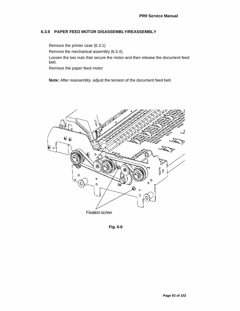
PR9 Service Manual
Page 93 of 102
6.3.9 PAPER FEED MOTOR DISASSEMBLY/REASSEMBLY
Remove the printer case (6.3.1) Remove the mechanical assembly (6.3.4). Loosen the two nuts that secure the motor and then release the document feed belt. Remove the paper feed motor Note: After reassembly, adjust the tension of the document feed belt.
Fixation screw
Fig. 6-6
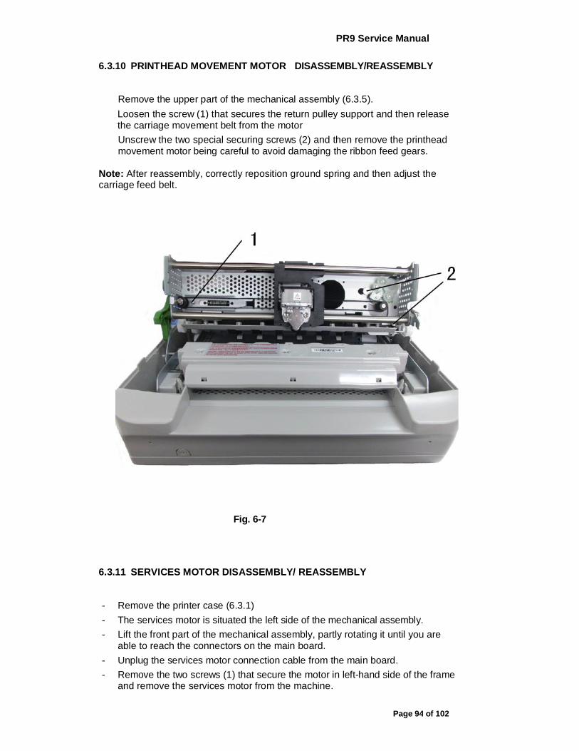
PR9 Service Manual
Page 94 of 102
6.3.10 PRINTHEAD MOVEMENT MOTOR DISASSEMBLY/REASSEMBLY
Remove the upper part of the mechanical assembly (6.3.5). Loosen the screw (1) that secures the return pulley support and then release the carriage movement belt from the motor Unscrew the two special securing screws (2) and then remove the printhead movement motor being careful to avoid damaging the ribbon feed gears.
Note: After reassembly, correctly reposition ground spring and then adjust the carriage feed belt.
Fig. 6-7
6.3.11 SERVICES MOTOR DISASSEMBLY/ REASSEMBLY
- Remove the printer case (6.3.1) - The services motor is situated the left side of the mechanical assembly. - Lift the front part of the mechanical assembly, partly rotating it until you are
able to reach the connectors on the main board. - Unplug the services motor connection cable from the main board. - Remove the two screws (1) that secure the motor in left-hand side of the frame
and remove the services motor from the machine.
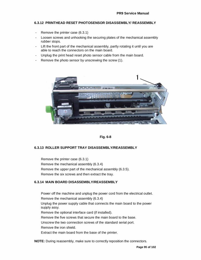
PR9 Service Manual
Page 95 of 102
6.3.12 PRINTHEAD RESET PHOTOSENSOR DISASSEMBLY/ REASSEMBLY
- Remove the printer case (6.3.1) - Loosen screws and unhooking the securing plates of the mechanical assembly
rubber stops. - Lift the front part of the mechanical assembly, partly rotating it until you are
able to reach the connectors on the main board. - Unplug the print head reset photo sensor cable from the main board. - Remove the photo sensor by unscrewing the screw (1).
Fig. 6-8
6.3.13 ROLLER SUPPORT TRAY DISASSEMBLY/REASSEMBLY
Remove the printer case (6.3.1) Remove the mechanical assembly (6.3.4) Remove the upper part of the mechanical assembly (6.3.5). Remove the six screws and then extract the tray.
6.3.14 MAIN BOARD DISASSEMBLY/REASSEMBLY
Power off the machine and unplug the power cord from the electrical outlet. Remove the mechanical assembly (6.3.4) Unplug the power supply cable that connects the main board to the power supply assy. Remove the optional interface card (if installed). Remove the five screws that secure the main board to the base. Unscrew the two connection screws of the standard serial port. Remove the iron shield. Extract the main board from the base of the printer.
NOTE: During reassembly, make sure to correctly reposition the connectors.

PR9 Service Manual
Page 96 of 102
6.3.15 POWER SUPPLY ASSY DISASSEMBLY/REASSEMBLY
Remove the mechanical assembly (6.3.4)
Unplug the power supply cable (1) from the main board. Unscrews the four screws that secure the power supply and also remove the ground wires. Loosen the two screws that secure the switch. Extract the power supply assy.
Note: During reassembly, make sure that you correctly reposition the ground cables.
6.3.16 FEEDER PHOTOSENSORS DISASSEMBLY/REASSEMBLY
Remove the mechanical assembly. Unscrews the eight screws that left 4 and right four then Remove the white paper feed platform. Remove the clasp, the black plate and the white gear that secures the square shaft in left which under the photo sensors and also remove another in the opposite. Remove the plastic axle sleeve that secures the square shaft. Remove the clasp that secures the paper feed roller in left and right. Remove the black plate and the gear. Remove the copper axle sleeve Remove the pressure sensor cable (blue) connector from the front feeder photo sensors board. Remove the white plastic cover that covers the front feeder photo sensors after removing its four screws. Remove the front feeder photo sensors by pulling its paper feed roller and square shaft out, using your left and right hand. Remove the square shaft. . Unscrew the four screws that secure the feeder photo sensors board and then remove the feeder photo sensors board, the document stop bar slide-proof fins and paper feed roller.
NOTE: 1. During reassembly, make sure to correctly reposition the two springs. 2. There are two plastic plate the one have notch must assembling inside
that secures the paper feed roller however another must out side.
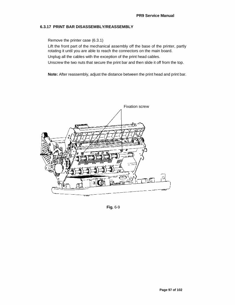
PR9 Service Manual
Page 97 of 102
6.3.17 PRINT BAR DISASSEMBLY/REASSEMBLY
Remove the printer case (6.3.1) Lift the front part of the mechanical assembly off the base of the printer, partly rotating it until you are able to reach the connectors on the main board. Unplug all the cables with the exception of the print head cables. Unscrew the two nuts that secure the print bar and then slide it off from the top. Note: After reassembly, adjust the distance between the print head and print bar.
Fixation screw
Fig. 6-9
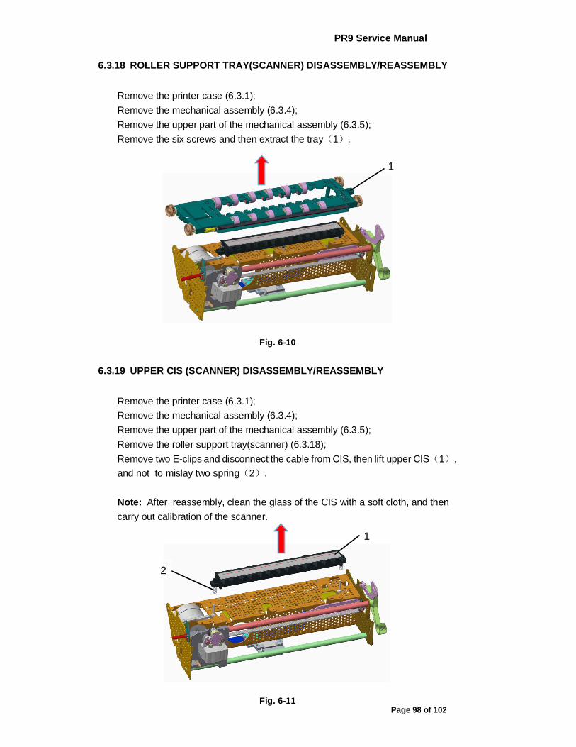
PR9 Service Manual
Page 98 of 102
6.3.18 ROLLER SUPPORT TRAY(SCANNER) DISASSEMBLY/REASSEMBLY
Remove the printer case (6.3.1); Remove the mechanical assembly (6.3.4); Remove the upper part of the mechanical assembly (6.3.5); Remove the six screws and then extract the tray(1).
Fig. 6-10
6.3.19 UPPER CIS (SCANNER) DISASSEMBLY/REASSEMBLY
Remove the printer case (6.3.1); Remove the mechanical assembly (6.3.4); Remove the upper part of the mechanical assembly (6.3.5); Remove the roller support tray(scanner) (6.3.18); Remove two E-clips and disconnect the cable from CIS, then lift upper CIS(1), and not to mislay two spring(2). Note: After reassembly, clean the glass of the CIS with a soft cloth, and then carry out calibration of the scanner.
Fig. 6-11
1
1
2

PR9 Service Manual
Page 99 of 102
6.3.20 TRANSMISSION SHAFT(SCANNER) DISASSEMBLY/REASSEMBLY
Remove the printer case (6.3.1); Remove the mechanical assembly (6.3.4); Remove the service motor (6.3.11); Remove E-clip(1) ,the driving gear_SC(2), sintering bearing(3); Remove two screws(4) on the top of the mechanical assembly and then extract the transmission shaft(scanner) (5). Note: After reassembly,correct tensioning of the alignment timing belt(6).
Fig. 6-12
2
3
1
5
4
6
5
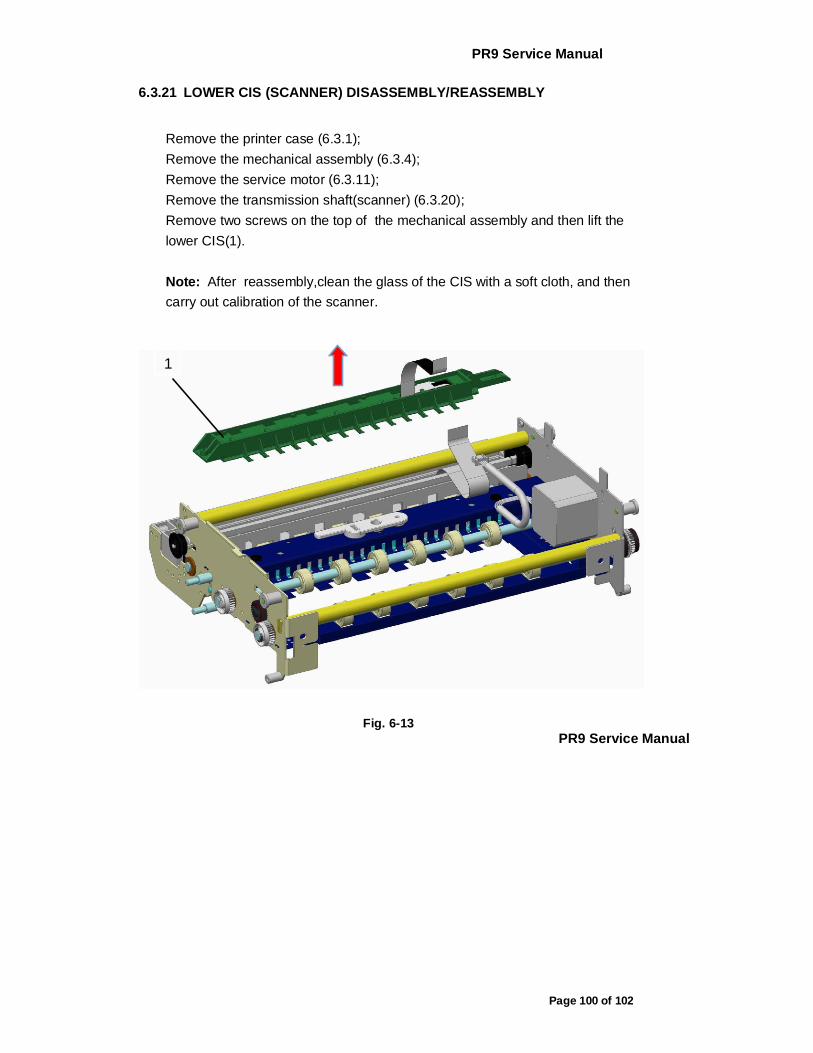
PR9 Service Manual
Page 100 of 102
6.3.21 LOWER CIS (SCANNER) DISASSEMBLY/REASSEMBLY
Remove the printer case (6.3.1); Remove the mechanical assembly (6.3.4); Remove the service motor (6.3.11); Remove the transmission shaft(scanner) (6.3.20); Remove two screws on the top of the mechanical assembly and then lift the lower CIS(1). Note: After reassembly,clean the glass of the CIS with a soft cloth, and then carry out calibration of the scanner.
Fig. 6-13
PR9 Service Manual
1
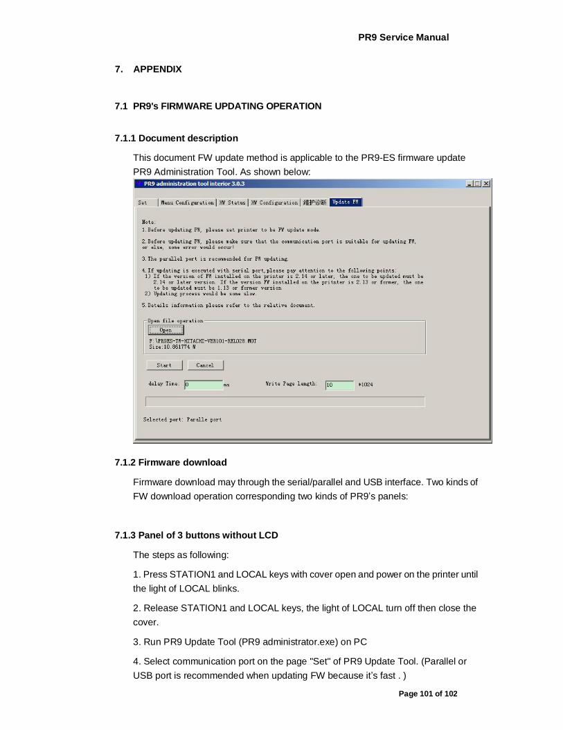
PR9 Service Manual
Page 101 of 102
7. APPENDIX
7.1 PR9's FIRMWARE UPDATING OPERATION
7.1.1 Document description
This document FW update method is applicable to the PR9-ES firmware update PR9 Administration Tool. As shown below:
7.1.2 Firmware download
Firmware download may through the serial/parallel and USB interface. Two kinds of FW download operation corresponding two kinds of PR9’s panels:
7.1.3 Panel of 3 buttons without LCD
The steps as following:
1. Press STATION1 and LOCAL keys with cover open and power on the printer until the light of LOCAL blinks.
2. Release STATION1 and LOCAL keys, the light of LOCAL turn off then close the cover.
3. Run PR9 Update Tool (PR9 administrator.exe) on PC
4. Select communication port on the page "Set" of PR9 Update Tool. (Parallel or USB port is recommended when updating FW because it’s fast . )

PR9 Service Manual
Page 102 of 102
5. On the page "Update FW" of PR9 Update Tool, open the firmware file and click "Start" button to
start updating.
6. After the updating is finished successfully, PR9 will restart automatically.
(Simple: Open the printer coverà press and hold the [STATION1+LOCAL] keysàpower on the printerà the light LOCAL blinksàrelease two keysàclosing coveràopen the Update tool and select interfaceà open the firmware file and start updateàUpdate is finished àprinter restart)

PR9 Service Manual
Page 103 of 102
7.1.4 Panel of 5 buttons with LCD
The steps as following:
1. Press the ■STOP key and power on the printer, release ■STOP key till the PR9’s LCD displays “RELEASE STOP KEY”. After release STOP key, the PR9’s LCD displays “PROGRAM UPDATE”.
2. Run PR9 Update Tool (PR9 administrator.exe) on PC
3. Select communication port on the page "Set" of PR9 Update Tool. Parallel or USB port is recommended because it’s fast.
4. On the page "Update FW" of PR9 Update Tool, open the firmware file and click "Start" button to start updating.
5. After the updating is finished successfully, PR9’s LCD displays “UPDATE O.K.”. PR9 will restart automatically.
(Simple: Press the [STOP] keyàpower on the PR9à LCD displays “RELEASE STOP KEY”àrelease STOP keyà LCD shows “PROGRAM UPDATE”à open the Update tool and select interfaceà open the firmware file and start updateà the update is finished àprinter restart)

PR9 Service Manual
Page 104 of 102
Flow chart as below:

PR9 Service Manual
Page 105 of 102
The interface as following:
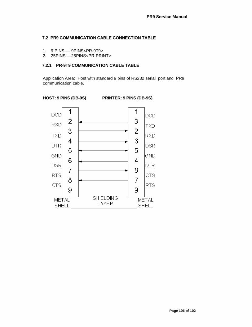
PR9 Service Manual
Page 106 of 102
7.2 PR9 COMMUNICATION CABLE CONNECTION TABLE
1. 9 PINS-— 9PINS<PR-9T9> 2. 25PINS-—25PINS<PR-PRINT>
7.2.1 PR-9T9 COMMUNICATION CABLE TABLE
Application Area: Host with standard 9 pins of RS232 serial port and PR9 communication cable.
HOST: 9 PINS (DB-9S) PRINTER: 9 PINS (DB-9S)

PR9 Service Manual
Page 107 of 102
7.2.2 THE PARALLEL COMMUNICATION CABLE TABLE OF PR9 CONNECT
TO THE HOST
Application Area: host with standard Centronics IEEE parallel interface and PR9 communication cable. HOST 25 PINS
PR9 36 PINS