ppt
46
GLASS BY SWEETY SHARMA M.Phil ( course work), department of forensic science Punjabi university, Patiala
-
Upload
sweety-sharma -
Category
Science
-
view
89 -
download
0
Transcript of ppt

GLASS
BY SWEETY SHARMA
M.Phil ( course work), department of forensic science
Punjabi university, Patiala

What is glassHard, amorphous solid
Usually transparent
Primarily composed of silica, with various amounts of elemental oxides
Brittle
The (ASTM) defines glass as “ an inorganic product of fusion which has cooled to a rigid condition without crystallizing. ”
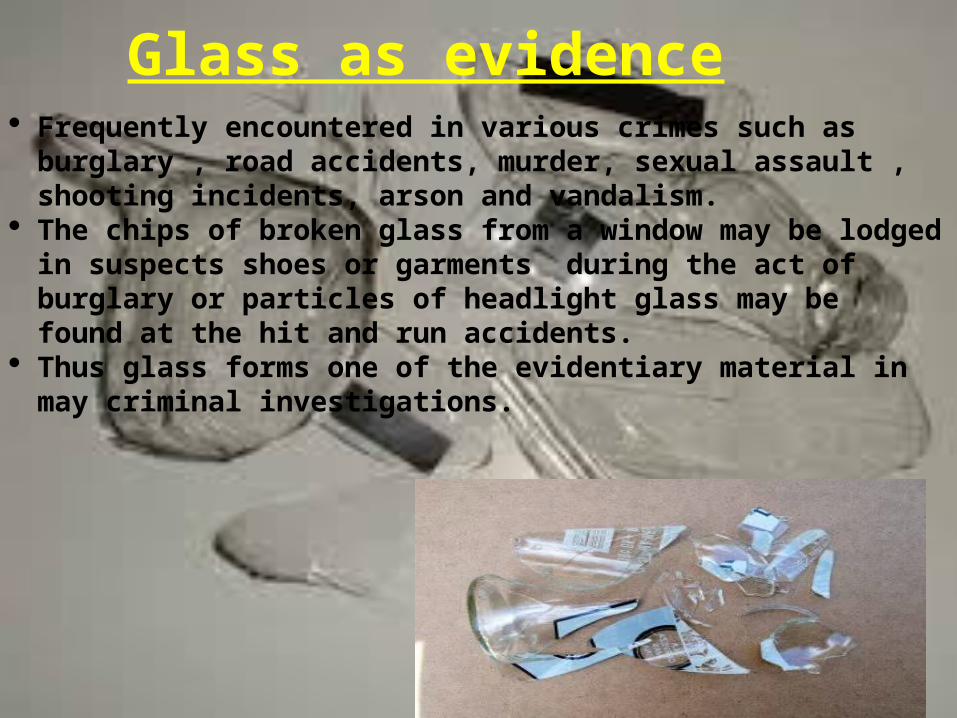
Glass as evidence Frequently encountered in various crimes such as burglary , road
accidents, murder, sexual assault , shooting incidents, arson and vandalism.
The chips of broken glass from a window may be lodged in suspects shoes or garments during the act of burglary or particles of headlight glass may be found at the hit and run accidents.
Thus glass forms one of the evidentiary material in may criminal investigations.

Types of glasses
• Soda lime – most common type, used for manufacturing
windows glass, bottles, containers , bulbs , bangles etc. common metal oxides found in this glass are Na, Ca, Mg, Al
• Borosilicate – Any glass having substantial amount of boron (5
% B2O3), resistant to heat, acid corrosion & alkalies, also known as PYREX, in manufacture of lab glass wares, thermometers, head light of automobile

• Safety glass (reduce likelihood of injury 2 persons)• Tempered – made stronger by rapid cooling & heating
of glass. Breaks into dices, with little splintering.• Laminated – prepared by sandwiching layer of plastic
materials b/w 2 pieces of ordinary window• Wire – single sheet of glass with meshed layer of wire.• Colored – produced by addition of metallic oxides to
soda lime.• Light sensitive glass- colloidal particles of silver halide.• Silica glass- made from molten quartz
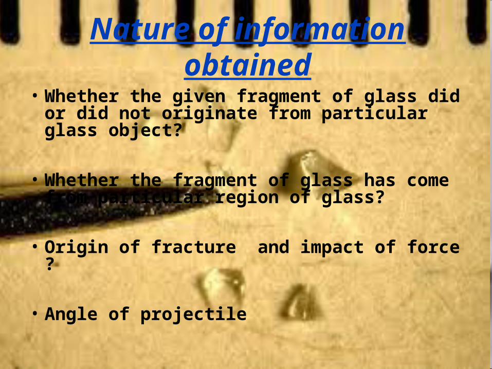
Nature of information obtained
• Whether the given fragment of glass did or did not originate from particular glass object?
• Whether the fragment of glass has come from particular region of glass?
• Origin of fracture and impact of force ?
• Angle of projectile
glass fractures examination
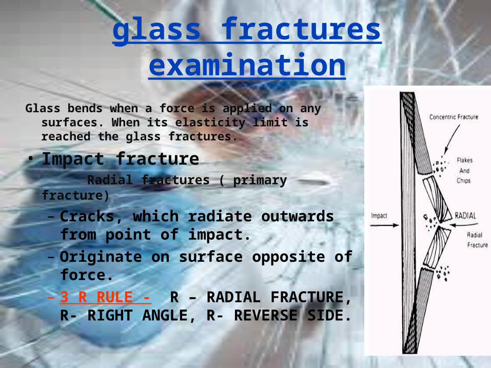
Glass bends when a force is applied on any surfaces. When its elasticity limit is reached the glass fractures.
• Impact fracture Radial fractures ( primary fracture)
– Cracks, which radiate outwards from point of impact.
– Originate on surface opposite of force.– 3 R RULE - R – RADIAL FRACTURE, R-
RIGHT ANGLE, R- REVERSE SIDE.
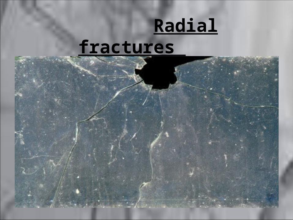
Radial fractures
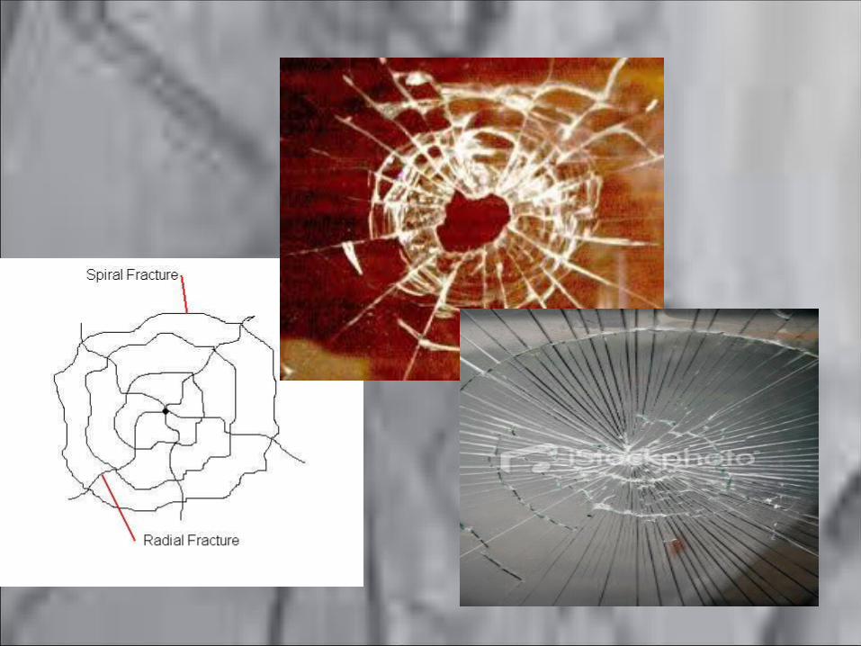
• Concentric fractures (secondary fracture)
– Series of broken circles around point of impact.– Originate from opposite of radial fractures– Glass bends on opposite side, then stretches and
breaks on side from which original blow was applied.
– Extend from one radial fracture to another.

• Cone fracture - a high velocity projectile such as bullet when penetrates the glass leaves a round crater shaped hole, surrounded by radial and concentric cracks .
– Hole - wider on exit side - appearance of cone.
– determine point of impact & direction of impact.

• Rib / stress line – Edges of broken pieces bear a number of curved
lines, termed as stress line.
– HECKLE MARKS – small straight lines on broken edge of glass, appear perpendicular to rib marks.
Sequence of holes in glass
A radial fracture in glass travel for some distance, depending upon the force of impact, but if it meets another fracture that has been formed earlier, it will terminate at that point.
– Consequently if fracture from one bullet are stopped by those made by another bullet hole, it may be deduced that the latter was made first.

Angle of impact
Can be determined by amount of chipping on exit side.
• Right angle- chipping evenly distributed- symmetrical hole
• Right of glass- chipping left surface of exit side- elliptical hole.
• Left of glass- reversed
Velocity and distance of firing
• High velocity bullet - circular hole - w/o much cracking.
• From long distance – much of the velocity will be spent , so will break the pane much in same way as stone does.
• Close range bullet will shatter the glass due 2 muzzle blast leaving powder residsue on the surface.

Fractures due to heat
• Irregular wavy pattern. • Glass splinters will usually fall on the side of
heat.• If heat is localized, a piece of glass
corresponding to that area will break off.
Backward fragmentation
• When a sheet of glass is broken, although most of the fragments travel in direction of the force, but many fine chips are also thrown backwards.
• These fine chips may be found on the clothing of perpetrator.

EXAMINATION
Physical comparison
1. Appearance
1. Type of glass
Physical characteristics
Density—mass divided by volume
Refractive index (RI)—the measure of light bending due to a change in velocity when traveling from one medium to another.
R.I- velocity of light in vaccum/velocity of light in medium
Fractures
Color
Thickness
Fluorescence
Markings—striations, dimples, etc.
Physical measurements
• 2 parameters – thickness and curvature• Edge thickness – measured by micrometer.• Curvature – measured by spherometer.
R = I² / 6h + h / 2 Where I -mean distance b/w legs of sphmtr. &
h - height of curved surface

Fluorescence under UV radiation
• Examination is to be done in dark room• Glass pieces (similar thickness)-washed with
acetone - have to be exposed in UV Radiation
• Luminescence / fluorescence property in glass is due ionic impurities or other elemental additives.
Physical matching
Principle - No two fractures will ever be identical over appreciable length.
1.A complimentary lateral fit along the broken edges over a length of quarter of inch establishes that two glass fragments were continuous before breaking.
Edges of the samples can seen with microscope of naked eyes, which will exactly fit into one another.
In case of non continuous glass patterns , match is made by seeing manufacturing marks, polish marks or striations marks with the help of diffused, incident, or oblique light or under comparison microscope of very low magnification

Density of various glasses
• Glass from various sources have different densities.
• Window glass, flat – 2.47 to 2.56• Head light glass – 2.47 to 2.63• Mica – 2.6 to 3.2• Quartz – 2.65• Glass, flint – 2.9 to 5.9• Diamond – 3.01 to 3.02
Density comparison by flotation• For this method, Bromoform (d=2.89) and Bromobenzene
(d=1.52) are selected. • The crime and control glass piece samples are to be crushed
to comparable sizes with similar shape. Each piece of glass is briefly sketched and marked for reference to return it to its original packet after examination.
• A cleaned and dried sample of crime glass particle is placed in a small beaker containing bromoform. The glass will float on the liquid surface. This indicates that the density of the liquid is greater than that of the glass.
• Add , Bromobenzene, drop wise with stirring, until the particle is exactly suspended.
• Add sample of control glass. If both the crime and the control glass particles remain suspended in the liquid, then, their densities
are equal to each other and to that of the liquid mixture. Particles of different densities will either sink or float, depending on whether they are more dense or less dense than the liquid medium.
• The density value of the particles of glass can be determined by calculating the density/ specific gravity of the flotation mixture using specific gravity bottle or a pycnometer

Density comparison by density gradient
• Principle - A standard density gradient tube is made up of layers of two liquids, mixed in varying proportions so that each layer has a different density value. When completed, a density gradient tube will usually have 6 to 10 layers, in which bottom layers have higher density.
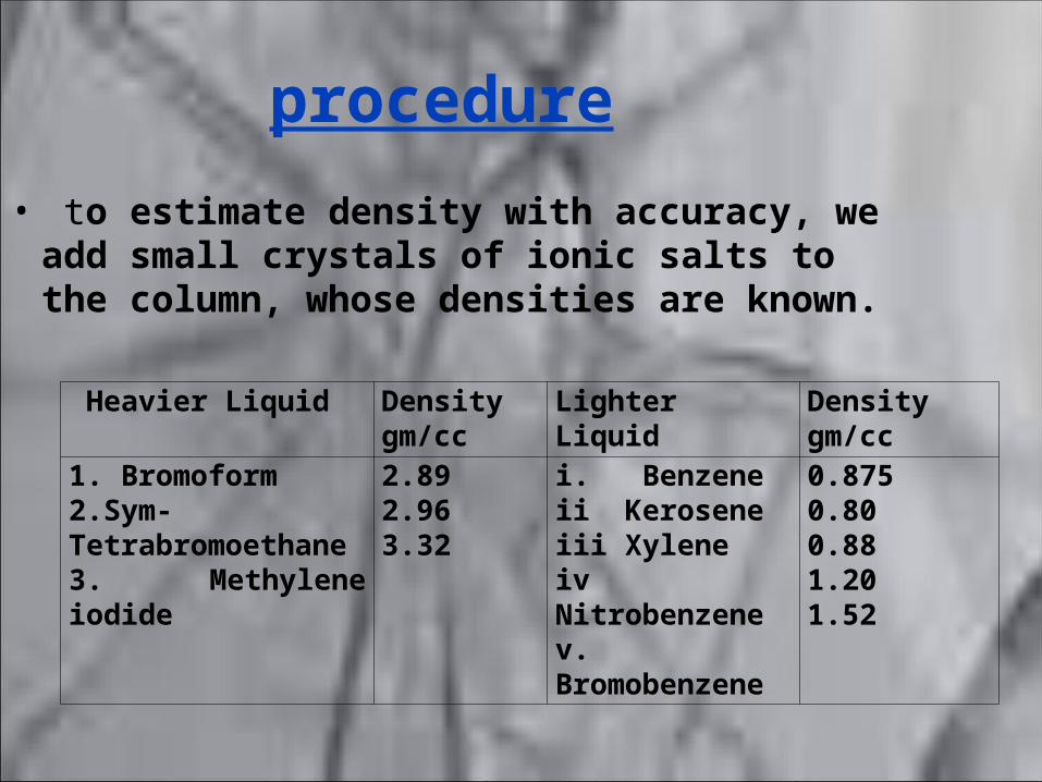
procedure
• to estimate density with accuracy, we add small crystals of ionic salts to the column, whose densities are known.
Heavier Liquid Density gm/cc
Lighter Liquid Density gm/cc
1. Bromoform2.Sym-Tetrabromoethane3. Methylene iodide
2.892.963.32
i. Benzeneii Keroseneiii Xyleneiv Nitrobenzenev. Bromobenzene
0.8750.800.881.201.52
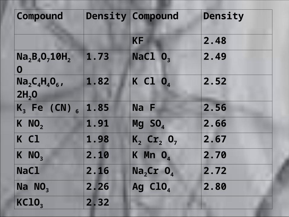
Compound Density Compound Density
KF 2.48
Na2B4O710H2 O 1.73 NaCl O3 2.49
Na2C4H4O6, 2H2O
1.82 K Cl O4 2.52
K3 Fe (CN) 6 1.85 Na F 2.56
K NO2 1.91 Mg SO4 2.66
K Cl 1.98 K2 Cr2 O7 2.67
K NO3 2.10 K Mn O4 2.70
NaCl 2.16 Na2Cr O4 2.72
Na NO3 2.26 Ag ClO4 2.80
KClO3 2.32

i)Place seven test tubes in a test tube rack.ii)Prepare the mixtures of bromobenzene and bromoform in the
following ratios, by pipetting out the respective liquids into the test tubes.
a) Pure bromoform-6ml (density -2.89)b) 1 ml of bromobenzene 5 ml of bromoformc) 2 ml of bromobenzene 4 ml of bromoformd) 3 ml of bromobenzene 3 ml of bromoforme) 4 ml of bromobenzene 2 ml of bromoformf) 5 ml of bromobenzene 1 ml of bromoformg) Pure bromobenzene-6ml (density -1.52)
•Mark off seven equal spaces-say 4 cms apart-along each of the two glass tubes of length 30 cms and place them in the tube stand.
•Carefully add the solutions in the order listed in step (ii) in to the tubes (Bromoform at the bottom).
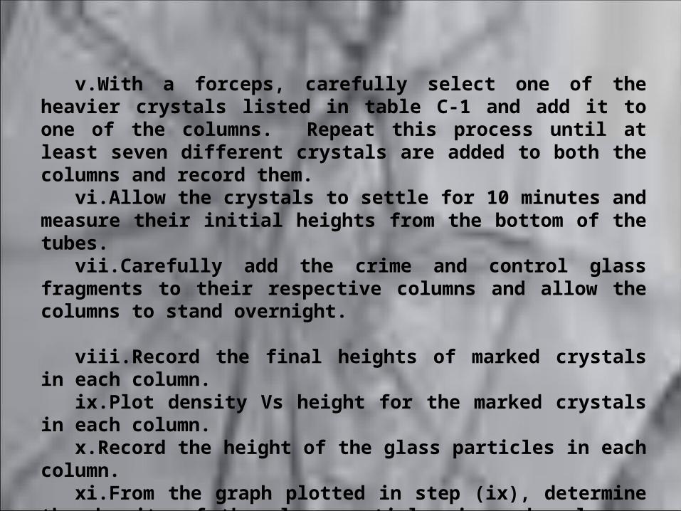
v.With a forceps, carefully select one of the heavier crystals listed in table C-1 and add it to one of the columns. Repeat this process until at least seven different crystals are added to both the columns and record them.
vi.Allow the crystals to settle for 10 minutes and measure their initial heights from the bottom of the tubes.
vii.Carefully add the crime and control glass fragments to their respective columns and allow the columns to stand overnight.
viii.Record the final heights of marked crystals in each column.ix.Plot density Vs height for the marked crystals in each column.x.Record the height of the glass particles in each column.xi.From the graph plotted in step (ix), determine the density of the
glass particles in each column. The data of the crystals used and graphs plotted as shown below:
a) Record of the crystals used for calibration.
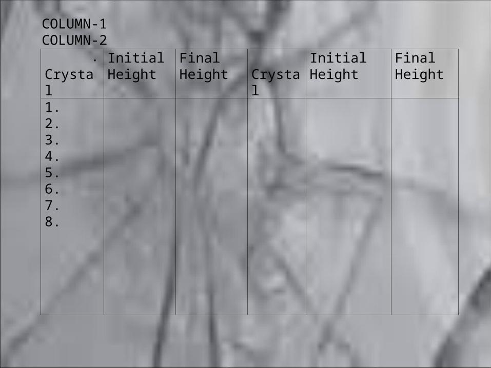
Crystal Initial Height
Final Height
Crystal Initial Height Final Height
1.2.3.4.5.6.7.8.
COLUMN-1 COLUMN-2.

Refractive Index
• varies with temperature as well as wavelength of the light source.
• represented as N20D where 20 represents the
temperature at which RI is measured, and for sodium D line. (Sodium lamp is used to obtain monochromatic light source.)
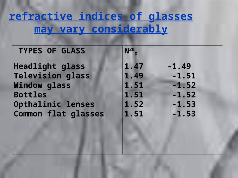
refractive indices of glasses may vary considerably
TYPES OF GLASS N20D
Headlight glassTelevision glassWindow glassBottlesOpthalinic lensesCommon flat glasses
1.47 -1.491.49 -1.511.51 -1.521.51 -1.521.52 -1.531.51 -1.53
Refractive index by immersion method
• Principle - When a transparent object, such as glass, is immersed in a liquid of same refractive index, it will be invisible because of the optical homogeneity of the system.

procedure
• (i) Place the glass fragment in a small beaker, after cleaning and drying.
• (ii) Select suitable liquids from the following: a) Di-n - butyl carbonate: N20
D = 1.411
b) Tri-n bytyl citrate: N20D = 1.455
c) Alpha – bromonapthalene: N20D = 1.658
d) Methylene iodide: N20D = 1.742
• (iii)Add liquid of lower index than glass in sufficient quantity to cover the glass piece

• (iv) Now, add in small amounts, the liquid of higher index of refraction, until the glass becomes invisible.
• (v) Remove the sample of liquid and determine its index of refraction using an Abbe refractometer. Abbe refractometers are available in the measuring ranges from 1.30 to 1.70 and from 1.45 to 1.84.
For measuring the refractive index of the liquid mixture -
Abbe refractometers
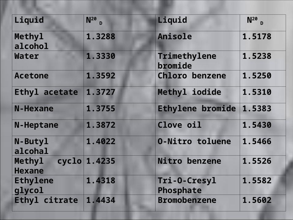
Liquid N20 D Liquid N20
D
Methyl alcohol 1.3288 Anisole 1.5178
Water 1.3330 Trimethylene bromide 1.5238
Acetone 1.3592 Chloro benzene 1.5250
Ethyl acetate 1.3727 Methyl iodide 1.5310
N-Hexane 1.3755 Ethylene bromide 1.5383
N-Heptane 1.3872 Clove oil 1.5430
N-Butyl alcohal 1.4022 O-Nitro toluene 1.5466
Methyl cyclo Hexane
1.4235 Nitro benzene 1.5526
Ethylene glycol 1.4318 Tri-O-Cresyl Phosphate
1.5582
Ethyl citrate 1.4434 Bromobenzene 1.5602

BECKE LINE CONCEPT• Becke line is the contrast (halo or bright border), which outlines the
transparent irregular particle, immersed in a liquid of different refractive index. This halo disappears, when the liquid medium and the transparent object have the same refractive index. Thus, when glass particles are immersed in a liquid medium, the Becke lines will appear due to the difference in the refractive indices of the glass and liquid. When the indices are equal, the Becke lines will disappear and this point is known as ‘match point.’
• An important advantage of the Becke line is that, it not only indicates a difference between the indices of the glass and liquid, but also indicates, which possesses the higher value. Thus, when the focus of the microscope is raised, the Becke line moves towards the medium of higher refractive index and if the focus is lowered, it moves towards the medium of lower refractive index. This observation allows the examiner to properly select a liquid that most closely matches the refractive index of glass.
REFERENCES
•Saferstein : criminalistics, 1976, prentice hall inc., USA.•Laboratory physics manual – forensic physics , directorate of forensic science , MHA, Govt. of india.•B.S Nabar: forensic science in crime investigation , 1988, haritha graphics, Hyderabad•B.R. Sharma : forensic science in criminal invesigation and trials, central law agency , allahabad.1974.•Saferstein : Forensic science, handbook, vol. 1 , prentice hall inc. USA.
Thankyou