PPC-L158T user manual ed.1 -...
56
User Manual PPC-L158T Intel Atom Processor- Based Panel PC with 15” Color TFT LCD Display
Transcript of PPC-L158T user manual ed.1 -...
User Manual
PPC-L158T
Intel Atom Processor- Based Panel PC with 15” Color TFT LCD Display
CopyrightThe documentation and the software included with this product are copyrighted 2011by Advantech Co., Ltd. All rights are reserved. Advantech Co., Ltd. reserves the rightto make improvements in the products described in this manual at any time withoutnotice. No part of this manual may be reproduced, copied, translated or transmittedin any form or by any means without the prior written permission of Advantech Co.,Ltd. Information provided in this manual is intended to be accurate and reliable. How-ever, Advantech Co., Ltd. assumes no responsibility for its use, nor for any infringe-ments of the rights of third parties, which may result from its use.
AcknowledgementsIntel and Pentium are trademarks of Intel Corporation.
Microsoft Windows and MS-DOS are registered trademarks of Microsoft Corp.
All other product names or trademarks are properties of their respective owners.
Product Warranty (2 years)Advantech warrants to you, the original purchaser, that each of its products will befree from defects in materials and workmanship for two years from the date of pur-chase.
This warranty does not apply to any products which have been repaired or altered bypersons other than repair personnel authorized by Advantech, or which have beensubject to misuse, abuse, accident or improper installation. Advantech assumes noliability under the terms of this warranty as a consequence of such events.
Because of Advantech’s high quality-control standards and rigorous testing, most ofour customers never need to use our repair service. If an Advantech product is defec-tive, it will be repaired or replaced at no charge during the warranty period. For out-of-warranty repairs, you will be billed according to the cost of replacement materials,service time and freight. Please consult your dealer for more details.
If you think you have a defective product, follow these steps:
1. Collect all the information about the problem encountered. (For example, CPU speed, Advantech products used, other hardware and software used, etc.) Note anything abnormal and list any onscreen messages you get when the problem occurs.
2. Call your dealer and describe the problem. Please have your manual, product, and any helpful information readily available.
3. If your product is diagnosed as defective, obtain an RMA (return merchandise authorization) number from your dealer. This allows us to process your return more quickly.
4. Carefully pack the defective product, a fully-completed Repair and Replacement Order Card and a photocopy proof of purchase date (such as your sales receipt) in a shippable container. A product returned without proof of the purchase date is not eligible for warranty service.
5. Write the RMA number visibly on the outside of the package and ship it prepaid to your dealer.
Part No. 200K158T10 Edition 1
Printed in China July 2011
PPC-L158T User Manual ii
Declaration of Conformity
CE
This product has passed the CE test for environmental specifications when shieldedcables are used for external wiring. We recommend the use of shielded cables. Thiskind of cable is available from Advantech. Please contact your local supplier forordering information.
CE
This product has passed the CE test for environmental specifications. Test conditionsfor passing included the equipment being operated within an industrial enclosure. Inorder to protect the product from being damaged by ESD (Electrostatic Discharge)and EMI leakage, we strongly recommend the use of CE-compliant industrial enclo-sure products.
FCC Class B
Note: This equipment has been tested and found to comply with the limits for a ClassB digital device, pursuant to part 15 of the FCC Rules. These limits are designed toprovide reasonable protection against harmful interference when the equipment isoperated in a commercial environment. This equipment generates, uses, and canradiate radio frequency energy and, if not installed and used in accordance with theinstruction manual, may cause harmful interference to radio communications. Opera-tion of this equipment in a residential area is likely to cause harmful interference inwhich case the user will be required to correct the interference at his own expense.
Technical Support and Assistance1. Visit the Advantech web site at www.advantech.com/support where you can find
the latest information about the product.2. Contact your distributor, sales representative, or Advantech's customer service
center for technical support if you need additional assistance. Please have the following information ready before you call:– Product name and serial number– Description of your peripheral attachments– Description of your software (operating system, version, application software,
etc.)– A complete description of the problem– The exact wording of any error messages
iii PPC-L158T User Manual
Safety Instructions1. Read these safety instructions carefully.2. Keep this User Manual for later reference.3. Disconnect this equipment from any AC outlet before cleaning. Use a damp
cloth. Do not use liquid or spray detergents for cleaning.4. For plug-in equipment, the power outlet socket must be located near the equip-
ment and must be easily accessible.5. Keep this equipment away from humidity.6. Put this equipment on a reliable surface during installation. Dropping it or letting
it fall may cause damage.7. The openings on the enclosure are for air convection. Protect the equipment
from overheating. DO NOT COVER THE OPENINGS.8. Make sure the voltage of the power source is correct before connecting the
equipment to the power outlet.9. Position the power cord so that people cannot step on it. Do not place anything
over the power cord.10. All cautions and warnings on the equipment should be noted.11. If the equipment is not used for a long time, disconnect it from the power source
to avoid damage by transient overvoltage.12. Never pour any liquid into an opening. This may cause fire or electrical shock.13. Never open the equipment. For safety reasons, the equipment should be
opened only by qualified service personnel.14. If one of the following situations arises, get the equipment checked by service
personnel:15. The power cord or plug is damaged.16. Liquid has penetrated into the equipment.17. The equipment has been exposed to moisture.18. The equipment does not work well, or you cannot get it to work according to the
user's manual.19. The equipment has been dropped and damaged.20. The equipment has obvious signs of breakage.21. DO NOT LEAVE THIS EQUIPMENT IN AN ENVIRONMENT WHERE THE
STORAGE TEMPERATURE MAY GO BELOW -20° C (-4° F) OR ABOVE 60° C (140° F). THIS COULD DAMAGE THE EQUIPMENT. THE EQUIPMENT SHOULD BE IN A CONTROLLED ENVIRONMENT.
22. CAUTION: DANGER OF EXPLOSION IF BATTERY IS INCORRECTLY REPLACED. REPLACE ONLY WITH THE SAME OR EQUIVALENT TYPE RECOMMENDED BY THE MANUFACTURER, DISCARD USED BATTERIES ACCORDING TO THE MANUFACTURER'S INSTRUCTIONS.
23. The sound pressure level at the operator's position according to IEC 704-1:1982 is no more than 70 dB (A).
DISCLAIMER: This set of instructions is given according to IEC 704-1. Advantechdisclaims all responsibility for the accuracy of any statements contained herein.
PPC-L158T User Manual iv

Safety Precaution - Static ElectricityFollow these simple precautions to protect yourself from harm and the products fromdamage.
To avoid electrical shock, always disconnect the power from your PC chassis before you work on it. Don't touch any components on the CPU card or other cards while the PC is on.
Disconnect power before making any configuration changes. The sudden rush of power as you connect a jumper or install a card may damage sensitive elec-tronic components.
v PPC-L158T User Manual

PPC-L158T User Manual vi
Contents
Chapter 1 General Information ............................11.1 Introduction ............................................................................................... 21.2 Specifications ............................................................................................ 2
1.2.1 General Specifications .................................................................. 21.2.2 Standard PC Functions................................................................. 21.2.3 Internal Graphics Specifications ................................................... 21.2.4 Audio Functions ............................................................................ 21.2.5 Ethernet Interface ......................................................................... 21.2.6 Touchscreen Specifications (Optional) ......................................... 3
Table 1.1: Touchscreen Specifications........................................ 31.2.7 Optional Modules .......................................................................... 31.2.8 Environment.................................................................................. 31.2.9 Certifications: ................................................................................ 3
1.3 Dimensions ............................................................................................... 4Figure 1.1 Dimensions of PPC-L158T ......................................... 4
Chapter 2 System Setup.......................................52.1 A Quick Tour of the Panel PC ................................................................... 6
Figure 2.1 Front Panel of PPC-L158T ......................................... 6Figure 2.2 Side View of the Panel PC ......................................... 6Figure 2.3 I/O Peripheral Connectors Panel of AC Input Model .. 7Figure 2.4 I/O Peripheral Connectors Panel of DC Input Model.. 7Figure 2.5 Rear View of the Panel PC......................................... 8
2.2 Preparing for First-time Use ...................................................................... 92.3 Installation Procedures.............................................................................. 9
2.3.1 Connecting the Power Cord.......................................................... 92.3.2 Connecting the Keyboard and Mouse........................................... 92.3.3 Switching on the Power ................................................................ 9
2.4 Running the BIOS Setup Program ............................................................ 92.5 Installing System Software........................................................................ 92.6 Installing the Drivers................................................................................ 10
Figure 2.6 Drivers and Utilities on the CD-ROM........................ 10
Chapter 3 Using the Panel PC............................113.1 Introduction ............................................................................................. 123.2 CD-ROM Drive (Optional) ....................................................................... 12
Figure 3.1 Inserting and ejecting a CD-ROM............................. 123.3 PS/2 Mouse and Keyboard ..................................................................... 133.4 PCI or PCIe Bus Expansion .................................................................... 13
Figure 3.2 PCI & PCIe Bus Expansion ...................................... 133.5 Serial COM Ports .................................................................................... 14
Figure 3.3 I/O Ports ................................................................... 143.6 VGA Port ................................................................................................. 153.7 USB Ports ............................................................................................... 153.8 Audio Interface ........................................................................................ 153.9 Ethernet................................................................................................... 15
3.10 Touchscreen (Optional)........................................................................... 15
Chapter 4 Hardware Installation ........................17
vii PPC-L158T User Manual
4.1 Jumpers and Connectors........................................................................ 184.2 Disassembling the Panel PC .................................................................. 18
Figure 4.1 Unfastening the Rear Cover..................................... 184.3 Installing the 2.5" Hard Disk Drive .......................................................... 19
Figure 4.2 The PPC Side Cover ................................................ 19Figure 4.3 The PPC HDD .......................................................... 19Figure 4.4 Plugging in the SATA Cable..................................... 20
4.4 Installing the DDR3 SDRAM Memory Module ........................................ 21Figure 4.5 Placing the Memory Module in the SODIMM Socket 21Figure 4.6 Stick the Thermal Pad on the Memory Heatsink ...... 21Figure 4.7 Fasten the Memory Heatsink onto the Board........... 22
4.5 Installing the Optical Device Drive .......................................................... 23Figure 4.8 Rear Cover Photo..................................................... 23Figure 4.9 Plug in the SATA ODD Cable................................... 23Figure 4.10Fasten Screw on IO Shielding.................................. 24Figure 4.11Fasten Screws on the ODD Bracket ........................ 24
4.6 Installing GPIO Cable ............................................................................. 25Figure 4.12GPIO Location on I/O Bracket.................................. 25Figure 4.13Change Cable PIN Header to CN11 ........................ 25
4.7 Installing the LPT Cable.......................................................................... 26Figure 4.14Insert LPT Cable PIN Header on the Motherboard .. 26Figure 4.15Fix the LPT Cable on the I/O Bracket....................... 27Figure 4.16Fasten the Screw on the Bracket ............................. 27Figure 4.17Completed Photo of LPT Cable Assemblage........... 27
4.8 Installing Dual-USB Cable ...................................................................... 28Figure 4.18Insert Dual-USB Cable on CN9 or CN10 ................. 28Figure 4.19Dual-USB Cable Assembly on I/O Bracket .............. 29Figure 4.20Fasten Screw on Bracket ......................................... 29Figure 4.21Completed Assembled Dual-USB Cable.................. 30
Chapter 5 Jumpers and Connectors................. 315.1 Jumpers and Connectors........................................................................ 32
5.1.1 Setting Jumpers.......................................................................... 325.1.2 Jumpers ...................................................................................... 33
Table 5.1: JP1 (CMOS Setting & AT / ATX Select)................... 33Table 5.2: CN19(Ring and Power for COM1/2 pin 9)................ 33
5.1.3 Jumper and Connector Locations............................................... 34Figure 5.1 Jumpers & Connectors on PPC-L158T Motherboard...
345.1.4 Connectors ................................................................................. 35
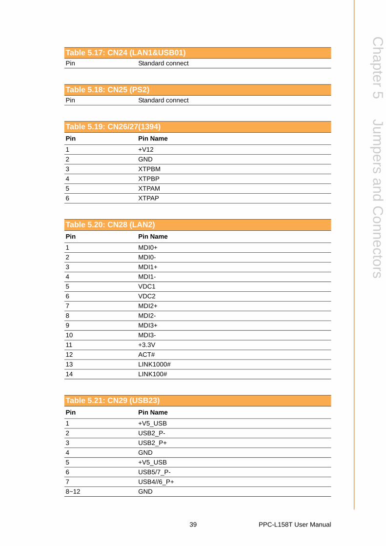
Table 5.3: CN1 (LVDS Back Light)............................................ 35Table 5.4: CN2/3 (SATA Power) ............................................... 36Table 5.5: CN4/5 (SATA0/1) ..................................................... 36Table 5.6: CN6 (LVDS) ............................................................. 36Table 5.7: CN7 (MiniPCIE)........................................................ 37Table 5.8: CN9/10 (USB4/5/6/7) ............................................... 37Table 5.9: CN11 (GPIO)............................................................ 37Table 5.10:CN12/13 (Memory 0/1)............................................. 37Table 5.11:CN14 (T/S) ............................................................... 37Table 5.12:CN18 (COM4) .......................................................... 38Table 5.13:CN20 (LED Connect) ............................................... 38Table 5.14:CN21 (Button) .......................................................... 38Table 5.15:CN22 (DC IN (For 12V))........................................... 38Table 5.16:CN23 (Speak)........................................................... 38Table 5.17:CN24 (LAN1&USB01) .............................................. 39Table 5.18:CN25 (PS2) .............................................................. 39Table 5.19:CN26/27(1394)......................................................... 39Table 5.20:CN28 (LAN2)............................................................ 39
PPC-L158T User Manual viii
Table 5.21:CN29 (USB23).......................................................... 39Table 5.22:CN30 (COM1&VGA)................................................. 40Table 5.23:CN31 (COM23)......................................................... 40Table 5.24:CN32 (MIC IN).......................................................... 40Table 5.25:CN33 (LINE OUT) .................................................... 40Table 5.26:CN34 (DC IN (For DC)) ............................................ 40
Chapter 6 Driver Installation ..............................416.1 Introduction ............................................................................................. 42
6.1.1 Driver Installation ........................................................................ 426.2 Updating Driver Search on the Advantech Website................................ 42
Appendix A PCI Card and PCIe Size Limits .........43A.1 PCIe Interface Card ................................................................................ 44A.2 PCI Interface Card .................................................................................. 44
ix PPC-L158T User Manual

PPC-L158T User Manual x

Chapter 1
1 General InformationThis chapter gives background information on the PPC-L158T.Sections include:
Specifications
Dimensions

1.1 IntroductionAdvantech PPC-L158T is an Intel Atom processor based Panel PC with a bright 15"LCD display. The powerful Atom CPU and Intel ICH8M chipsets bring the mostdynamic applications to life without sacrifices to any industrial reliability. The InternalCFast card interface can serve as an alternate HDD solution for OS booting and theMini PCIe interface can be used by many expansion cards such as a wireless LANcard to extend device mobility. In order to satisfy customers’ security concerns, PPC-L158T is also offered in a two Gigabit LAN port configuration. Four serial ports andfour USB V2.0 ports give the PPC-L158T advanced application capability.
1.2 Specifications
1.2.1 General Specifications Dimensions (W X H X D): 396.5 x 317.6 x 103.5 mm (15.6" x 12.5" x 4.08") Weight: 6 kg (13.22 lb) Power:
– DC Model: input voltage 15 ~ 24 V– AC Model: 85 W (Max)
Output Voltage: 100 ~ 240 Vac, 50 ~ 60 Hz, 1 ~ 2 A
1.2.2 Standard PC Functions CPU: Supports Intel® D525 processor up to 1.8 GHz BIOS: Award 8 MB Flash BIOS, supports plug and play, ACPI (advanced con-
figuration and power interface) Chipset: Intel D525/ICH8M RAM: Two 204-pin sockets up to 4 GB DDR3 SDRAM Serial ports: Four serial ports, COM1, 3 and 4 are RS-232; COM2 is RS-232/
422/485 Universal serial bus (USB) port: Supports up to four USB V2.0 ports Bus Expansion: PCI-e * 1; mini PCI-e *1; PCI or PCI-e bus expansion slot *1
1.2.3 Internal Graphics Specifications Intel Dynamic Video Memory Technology 4.0 400 MHz render clock frequency 2 display ports: LVDS and RGB Intel@ Clear Video Technology (MPEG2 Hardware Acceleration, ProcAmp)
1.2.4 Audio Functions Chipset: Realtek ALC892 Audio controller: Supports host/soft audio from the Intel ICH series chipset Stereo sound: Two stereo ADCs support 16/20/24-bit PCM format
1.2.5 Ethernet Interface 802.3x flow control support compliant IEEE 802.1p and 802.1q support 10/100/1000 IEEE 802.3 compliant
PPC-L158T User Manual 2
Chapter 1
GeneralInform
ation
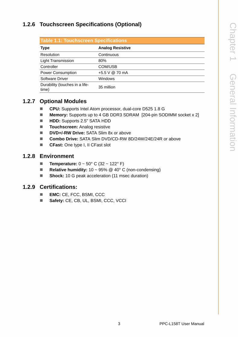
1.2.6 Touchscreen Specifications (Optional)
1.2.7 Optional Modules CPU: Supports Intel Atom processor, dual-core D525 1.8 G Memory: Supports up to 4 GB DDR3 SDRAM [204-pin SODIMM socket x 2] HDD: Supports 2.5" SATA HDD Touchscreen: Analog resistive DVD+/-RW Drive: SATA Slim 8x or above Combo Drive: SATA Slim DVD/CD-RW 8D/24W/24E/24R or above CFast: One type I, II CFast slot
1.2.8 Environment Temperature: 0 ~ 50° C (32 ~ 122° F) Relative humidity: 10 ~ 95% @ 40° C (non-condensing) Shock: 10 G peak acceleration (11 msec duration)
1.2.9 Certifications: EMC: CE, FCC, BSMI, CCC Safety: CE, CB, UL, BSMI, CCC, VCCI
Table 1.1: Touchscreen Specifications
Type Analog Resistive
Resolution Continuous
Light Transmission 80%
Controller COM/USB
Power Consumption +5.5 V @ 70 mA
Software Driver Windows
Durability (touches in a life- time)
35 million
3 PPC-L158T User Manual
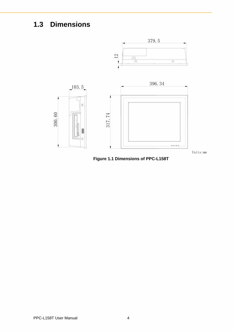
1.3 Dimensions
Figure 1.1 Dimensions of PPC-L158T
PPC-L158T User Manual 4
Chapter 2
2 System SetupThis chapter gives system setup information for the PPC-L158T.Sections include:
A Quick Tour
Installation Procedures
Running the BIOS Setup
Installing System software
2.1 A Quick Tour of the Panel PCBefore starting to set up the panel PC, take a moment to become familiar with thelocations and purposes of controls, drives, connectors and ports, which are illustrated
in the figures below.
When placed upright on the desktop, the front panel of the panel PC appears asshown in Figure 2.1.
Figure 2.1 Front Panel of PPC-L158T
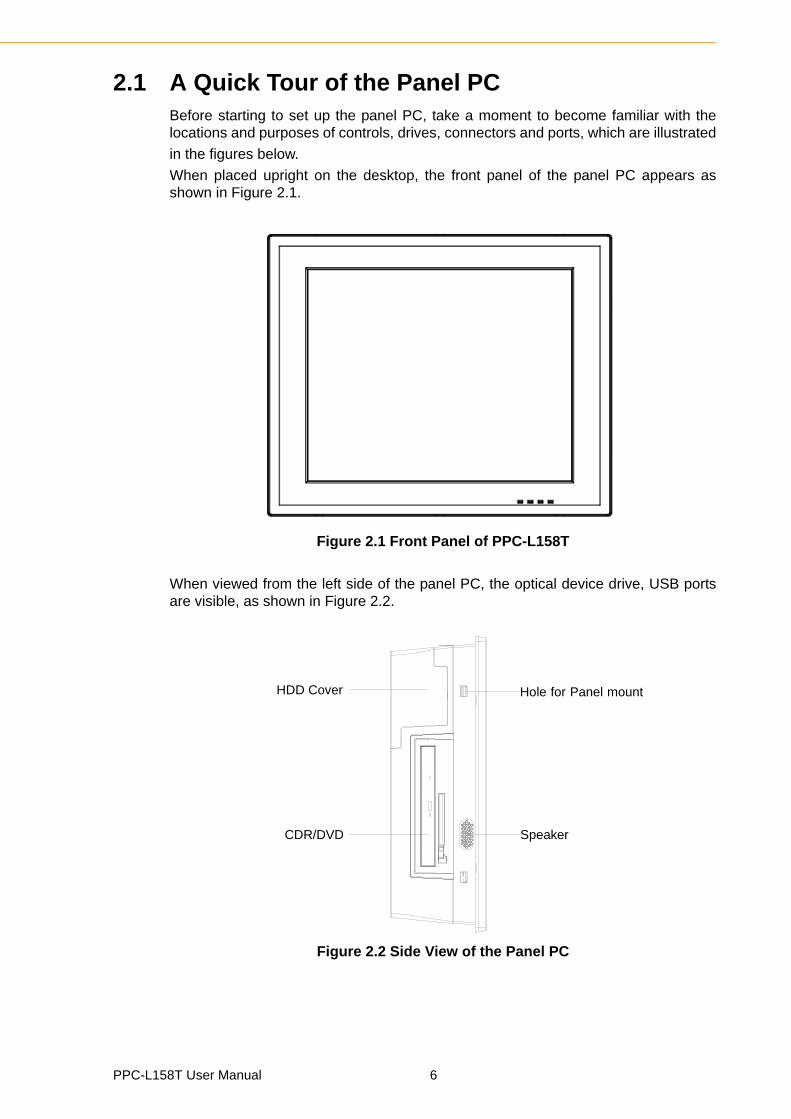
When viewed from the left side of the panel PC, the optical device drive, USB portsare visible, as shown in Figure 2.2.
Figure 2.2 Side View of the Panel PC
Hole for Panel mount
SpeakerCDR/DVD
HDD Cover
PPC-L158T User Manual 6
Chapter 2
System
Setup
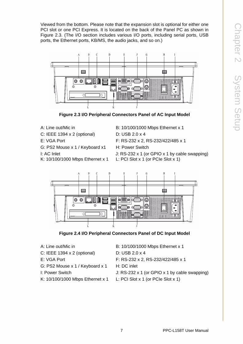
Viewed from the bottom. Please note that the expansion slot is optional for either onePCI slot or one PCI Express. It is located on the back of the Panel PC as shown inFigure 2.3. (The I/O section includes various I/O ports, including serial ports, USBports, the Ethernet ports, KB/MS, the audio jacks, and so on.)
Figure 2.3 I/O Peripheral Connectors Panel of AC Input Model
A: Line out/Mic in B: 10/100/1000 Mbps Ethernet x 1
C: IEEE 1394 x 2 (optional) D: USB 2.0 x 4
E: VGA Port F: RS-232 x 2, RS-232/422/485 x 1
G: PS2 Mouse x 1 / Keyboard x1 H: Power Switch
I: AC Inlet J: RS-232 x 1 (or GPIO x 1 by cable swapping)K: 10/100/1000 Mbps Ethernet x 1 L: PCI Slot x 1 (or PCIe Slot x 1)
Figure 2.4 I/O Peripheral Connectors Panel of DC Input Model
A: Line out/Mic in B: 10/100/1000 Mbps Ethernet x 1
C: IEEE 1394 x 2 (optional) D: USB 2.0 x 4
E: VGA Port F: RS-232 x 2, RS-232/422/485 x 1
G: PS2 Mouse x 1 / Keyboard x 1 H: DC inlet
I: Power Switch J: RS-232 x 1 (or GPIO x 1 by cable swapping)
K: 10/100/1000 Mbps Ethernet x 1 L: PCI Slot x 1 (or PCIe Slot x 1)
7 PPC-L158T User Manual
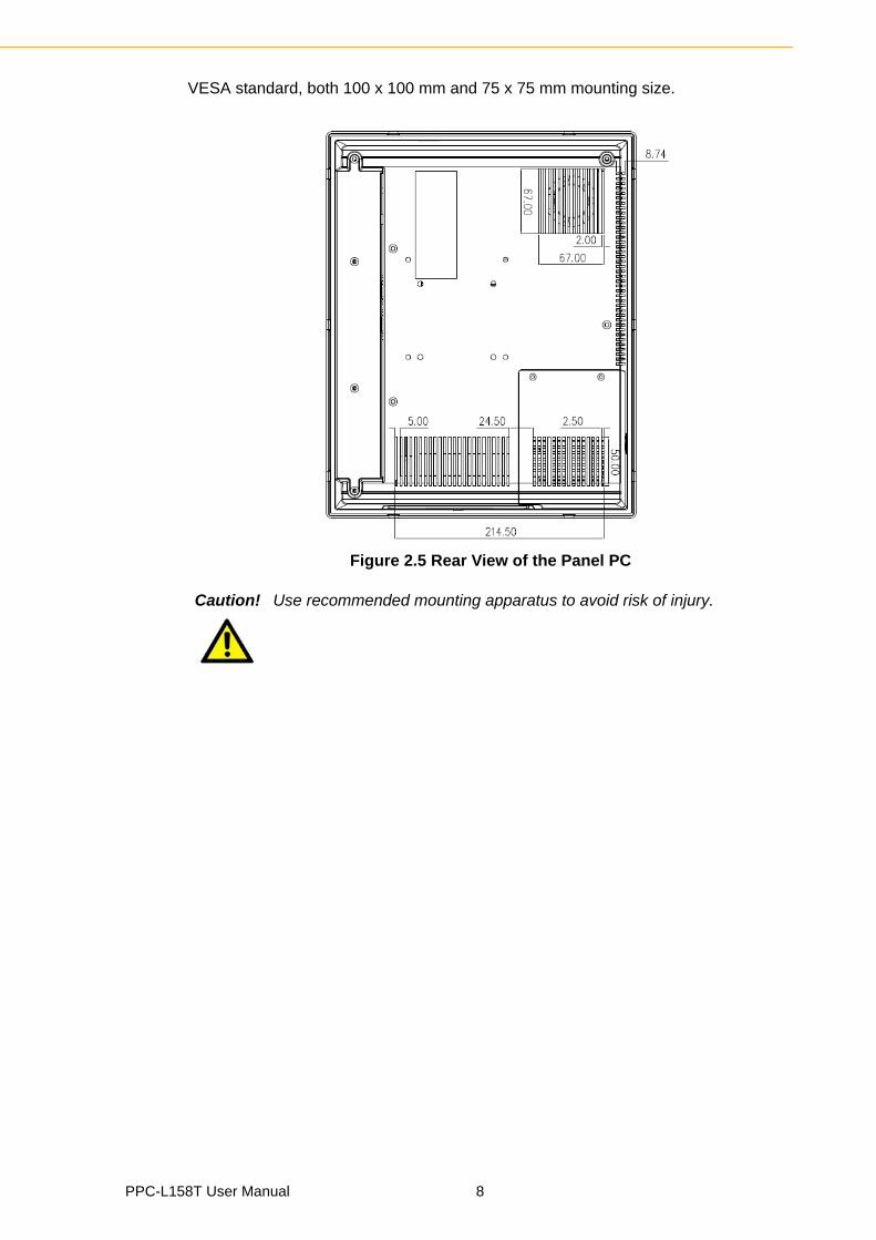
VESA standard, both 100 x 100 mm and 75 x 75 mm mounting size.
Figure 2.5 Rear View of the Panel PC
Caution! Use recommended mounting apparatus to avoid risk of injury.
PPC-L158T User Manual 8
Chapter 2
System
Setup
2.2 Preparing for First-time UseBefore commencing set up of the panel PC system, the following items should beavailable:
Keyboard Mouse (for system software installation)
2.3 Installation Procedures
2.3.1 Connecting the Power CordThe panel PC can be powered through an AC electrical outlet (100 ~ 250 volts,
50 ~ 60 Hz) or DC outlet (15 ~ 24 V). Be sure to handle the power cords by holdingthe plug ends only. Follow these procedures in order:
1. Connect the female end of the power cord to the AC/DC inlet of the panel PC.2. Connect the 3-pin male plug of the power cord to an electrical outlet.
2.3.2 Connecting the Keyboard and MouseConnect the mouse and keyboard to the I/O section of PPC. If using a serial mouseand the panel PC has a touchscreen, it is possible to connect the mouse to any COMport.
2.3.3 Switching on the PowerSwitch on the power switch, which is located inside the bottom side cover.
2.4 Running the BIOS Setup ProgramThe panel PC will be properly set up and configured by the dealer prior to delivery.However, it may be necessary to use the panel PC's BIOS (Basic Input-Output Sys-tem) setup program to change the system configuration information, such as the cur-rent date and time, or the type of hard drive. The setup program is stored in read-onlymemory (ROM). It can be accessed either when you turn on or reset the panel PC, bypressing the ‘Del’ key on your keyboard immediately after powering on the computer.
The settings specified with the setup program are recorded in a special area of mem-ory called “CMOS RAM”. This memory is backed up by a battery so that it will not beerased after turning off or resetting the system. Whenever the power is turned on, thesystem reads the settings stored in CMOS RAM and compares them to the equip-ment check conducted during the power on self-test (POST). If a problem occurs, anerror message will be displayed on screen, and the computer prompts the user to runthe setup program.
2.5 Installing System SoftwareRecent releases of operating systems from major vendors include setup programswhich load automatically and guide you through hard disk formatting and operatingsystem installation. The guidelines below will help determine the steps necessary toinstall the operating system onto the panel PC hard drive.
Note! Some distributors and system integrators may have already pre-installed system software prior to shipment.
9 PPC-L158T User Manual
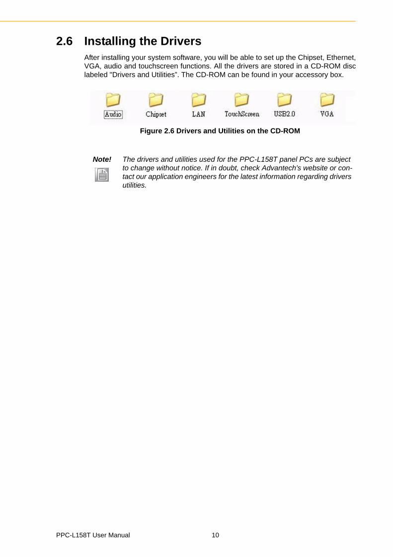
2.6 Installing the DriversAfter installing your system software, you will be able to set up the Chipset, Ethernet,VGA, audio and touchscreen functions. All the drivers are stored in a CD-ROM disclabeled "Drivers and Utilities”. The CD-ROM can be found in your accessory box.
Figure 2.6 Drivers and Utilities on the CD-ROM
Note! The drivers and utilities used for the PPC-L158T panel PCs are subject to change without notice. If in doubt, check Advantech's website or con-tact our application engineers for the latest information regarding drivers utilities.
PPC-L158T User Manual 10
Chapter 3
3 Using the Panel PCThis chapter explains onboard devices and peripheral I/O ports available on the PPC-L158T.Sections include:
CD-ROM Drive
PS/2 Mouse and Keyboard
PCI or PCIe Bus Expansion
Serial COM Ports
VGA Port
USB Ports
Audio Interface
Ethernet
Touchscreen (Optional)
3.1 IntroductionThis chapter describes basic features and procedures for using the panel PC. Topicscovered include: the CD-ROM drive, I/O ports and the touchscreen.
This product is a high performance panel PC, please keep upright (see Fig. 3.1).
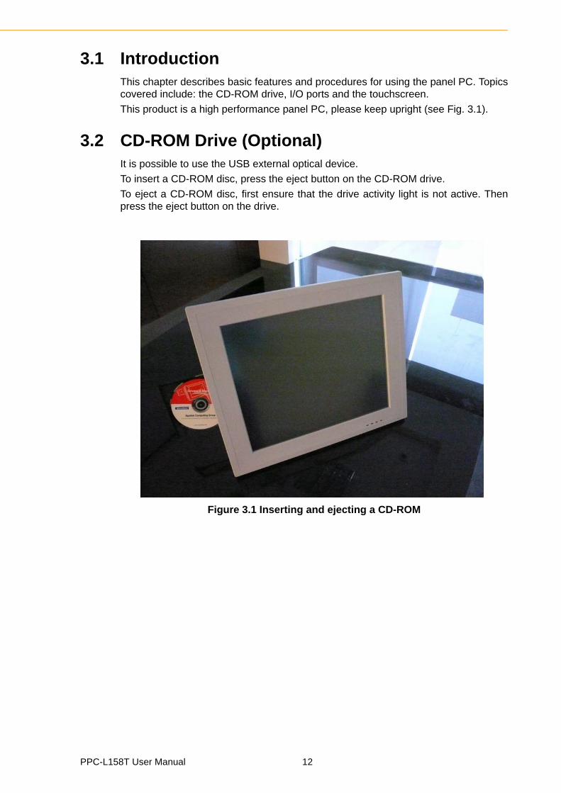
3.2 CD-ROM Drive (Optional)It is possible to use the USB external optical device.
To insert a CD-ROM disc, press the eject button on the CD-ROM drive.
To eject a CD-ROM disc, first ensure that the drive activity light is not active. Thenpress the eject button on the drive.
Figure 3.1 Inserting and ejecting a CD-ROM
PPC-L158T User Manual 12
Chapter 3
Using the
PanelP
C
3.3 PS/2 Mouse and Keyboard1. To install a full-size desktop PS/2 keyboard and mouse with the panel PC, follow
these instructions:2. Be sure the panel PC is turned off.3. Attach the keyboard to the purple colored 5-pin PS/2 port.4. Attach the PS/2 mouse to the green colored port.5. Turn on the panel PC.
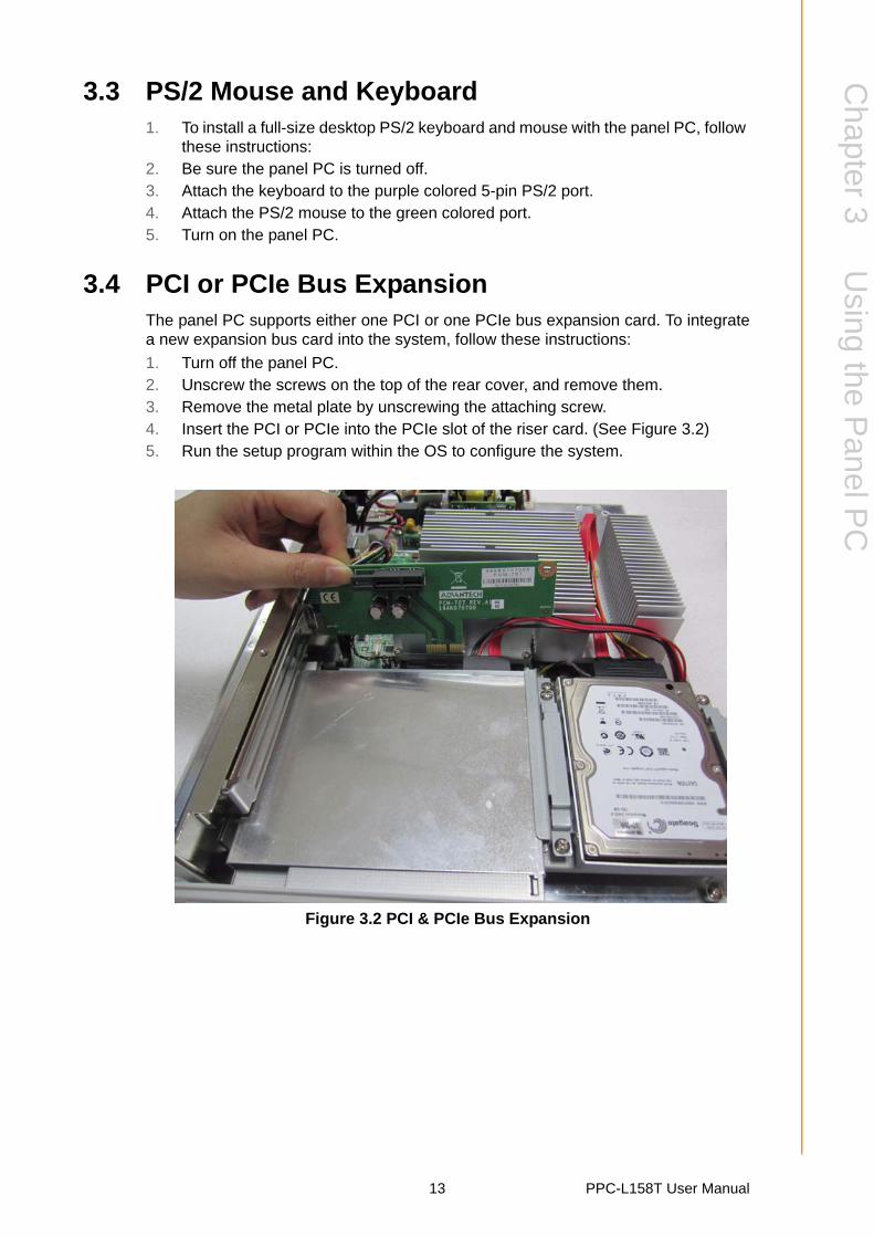
3.4 PCI or PCIe Bus ExpansionThe panel PC supports either one PCI or one PCIe bus expansion card. To integratea new expansion bus card into the system, follow these instructions:
1. Turn off the panel PC.2. Unscrew the screws on the top of the rear cover, and remove them.3. Remove the metal plate by unscrewing the attaching screw.4. Insert the PCI or PCIe into the PCIe slot of the riser card. (See Figure 3.2)5. Run the setup program within the OS to configure the system.
Figure 3.2 PCI & PCIe Bus Expansion
13 PPC-L158T User Manual
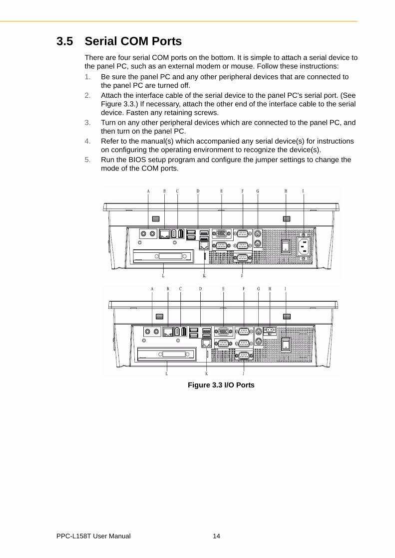
3.5 Serial COM PortsThere are four serial COM ports on the bottom. It is simple to attach a serial device tothe panel PC, such as an external modem or mouse. Follow these instructions:
1. Be sure the panel PC and any other peripheral devices that are connected to the panel PC are turned off.
2. Attach the interface cable of the serial device to the panel PC's serial port. (See Figure 3.3.) If necessary, attach the other end of the interface cable to the serial device. Fasten any retaining screws.
3. Turn on any other peripheral devices which are connected to the panel PC, and then turn on the panel PC.
4. Refer to the manual(s) which accompanied any serial device(s) for instructions on configuring the operating environment to recognize the device(s).
5. Run the BIOS setup program and configure the jumper settings to change the mode of the COM ports.
Figure 3.3 I/O Ports
PPC-L158T User Manual 14

Chapter 3
Using the
PanelP
C
3.6 VGA PortAn external VGA-compatible device may be connected to the system through the 15-pin external port located on the bottom of the system unit.
The panel PC simultaneously supports an external CRT monitor in addition to thebuilt-in LCD display.
1. Be sure the panel PC is turned off.2. Connect the external monitor to the system. (See Figure 3.3.)3. Turn on the panel PC and the external monitor.
3.7 USB PortsAn external USB device may be connected to the system through the 4-pin USBports located on the rear side and left side of the system unit.
1. Connect the external device to the system. (See Figure 3.3)2. The USB ports support hot plug-in connections. Install the device driver before
using the device.
3.8 Audio InterfaceThe audio interface includes two jacks: Microphone in and Line out. (See Figure 3.3)Their functions are:
Microphone in: Use an external microphone to record voice and sound. Line out: Output audio to external devices such as speakers or earphones.1. Connect the audio device to the system. (See Figure 3.3)2. Install the driver before using the device.
3.9 EthernetExternal devices on the network may be connected to the system through the exter-nal Ethernet port located on the bottom of the system unit.
1. Be sure the panel PC is turned off.2. Connect the external device(s) to the panel PC.3. Turn on the panel PC and the external device(s).
3.10 Touchscreen (Optional)The touchscreen is connected to the internal USB port. Its function is similar to that ofa mouse. PPC-L158T supports resistive touchscreen.
It is necessary to install the touchscreen driver before it will function. The touch-screen drivers for various operating systems are stored on the CD-ROM disc insidethe accessory box.
15 PPC-L158T User Manual

PPC-L158T User Manual 16
Chapter 4
4 Hardware InstallationThis chapter gives instructions for installing hardware devices on the PPC-L158T.Sections include:
Jumpers and Connectors
Disassembling the Panel PC
Installing the Central
Processing Unit (CPU)
Installing the DDR3 SDRAM Memory Module
4.1 Jumpers and ConnectorsThe panel PC consists of a PC-based computer that is housed in a metal shieldingcase with a plastic cover on the rear and bottom. All the computer devices, like theCPU, HDD, SDRAM, and power supply are all readily accessible after removing therear panel or the HDD cover. Any maintenance or hardware upgrades can be easilycompleted after removing the rear panel and/or HDD cover.
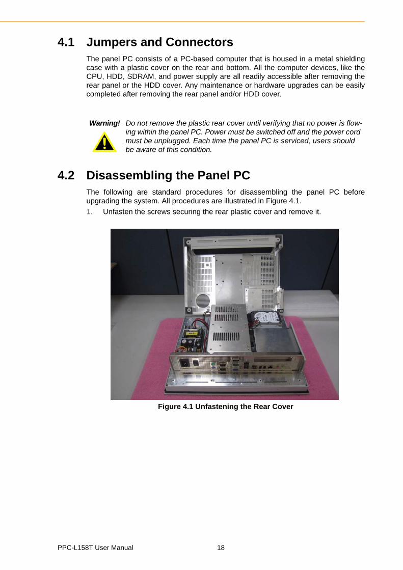
4.2 Disassembling the Panel PCThe following are standard procedures for disassembling the panel PC beforeupgrading the system. All procedures are illustrated in Figure 4.1.
1. Unfasten the screws securing the rear plastic cover and remove it.
Figure 4.1 Unfastening the Rear Cover
Warning! Do not remove the plastic rear cover until verifying that no power is flow-ing within the panel PC. Power must be switched off and the power cord must be unplugged. Each time the panel PC is serviced, users should be aware of this condition.
PPC-L158T User Manual 18
Chapter 4
Hardw
areInstallation
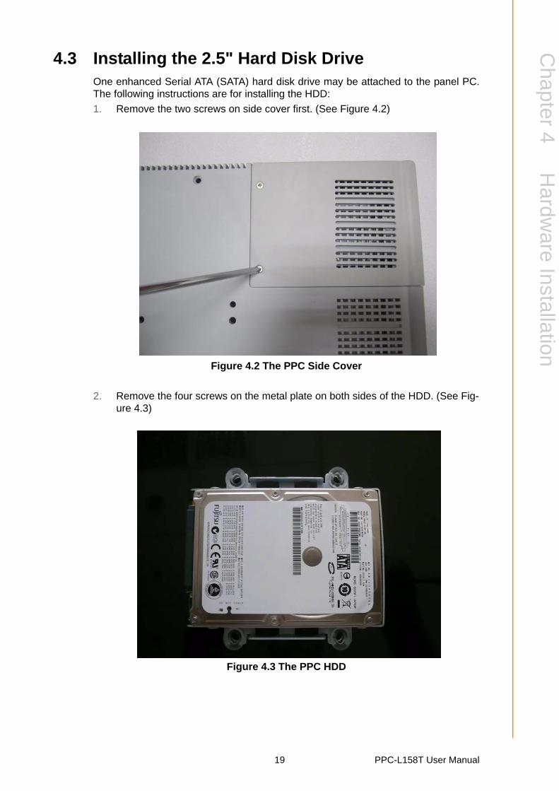
4.3 Installing the 2.5" Hard Disk DriveOne enhanced Serial ATA (SATA) hard disk drive may be attached to the panel PC.The following instructions are for installing the HDD:
1. Remove the two screws on side cover first. (See Figure 4.2)
Figure 4.2 The PPC Side Cover
2. Remove the four screws on the metal plate on both sides of the HDD. (See Fig-ure 4.3)
Figure 4.3 The PPC HDD
19 PPC-L158T User Manual
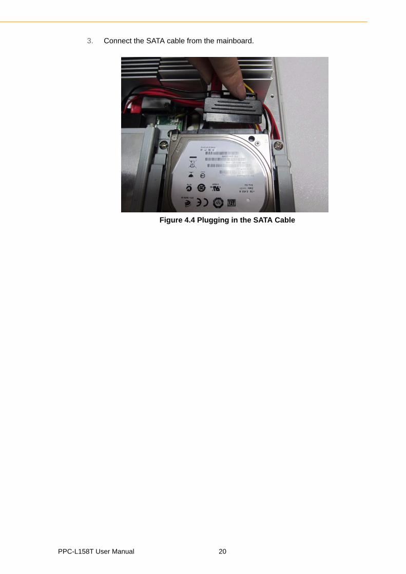
3. Connect the SATA cable from the mainboard.
Figure 4.4 Plugging in the SATA Cable
PPC-L158T User Manual 20
Chapter 4
Hardw
areInstallation
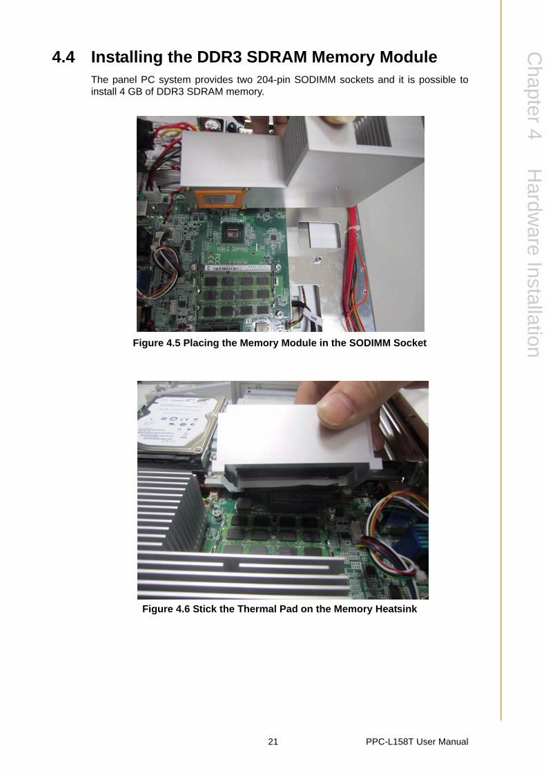
4.4 Installing the DDR3 SDRAM Memory ModuleThe panel PC system provides two 204-pin SODIMM sockets and it is possible toinstall 4 GB of DDR3 SDRAM memory.
Figure 4.5 Placing the Memory Module in the SODIMM Socket
Figure 4.6 Stick the Thermal Pad on the Memory Heatsink
21 PPC-L158T User Manual
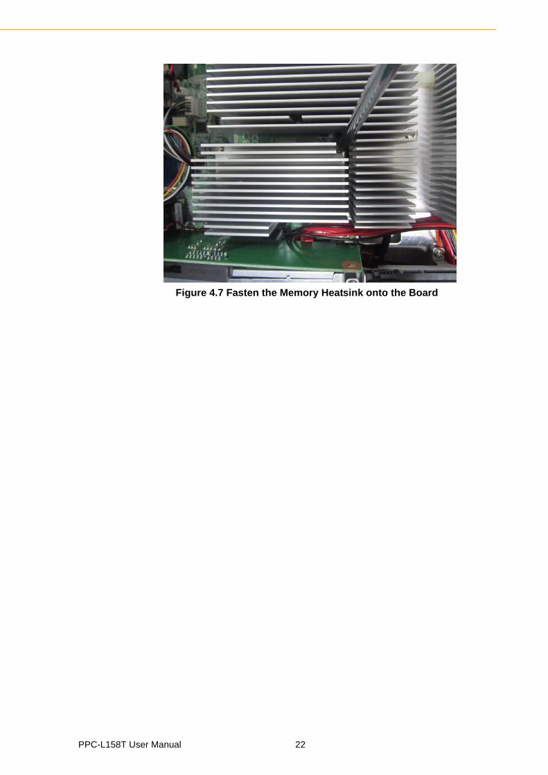
Figure 4.7 Fasten the Memory Heatsink onto the Board
PPC-L158T User Manual 22
Chapter 4
Hardw
areInstallation
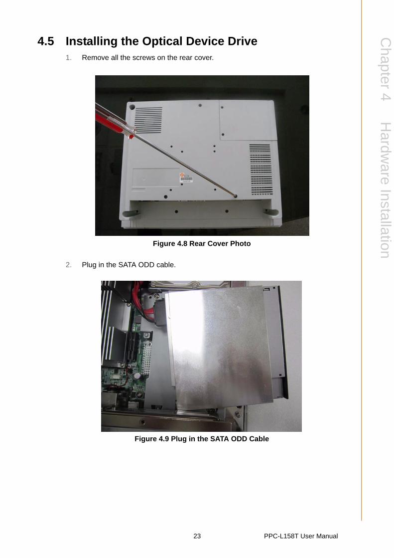
4.5 Installing the Optical Device Drive1. Remove all the screws on the rear cover.
Figure 4.8 Rear Cover Photo
2. Plug in the SATA ODD cable.
Figure 4.9 Plug in the SATA ODD Cable
23 PPC-L158T User Manual
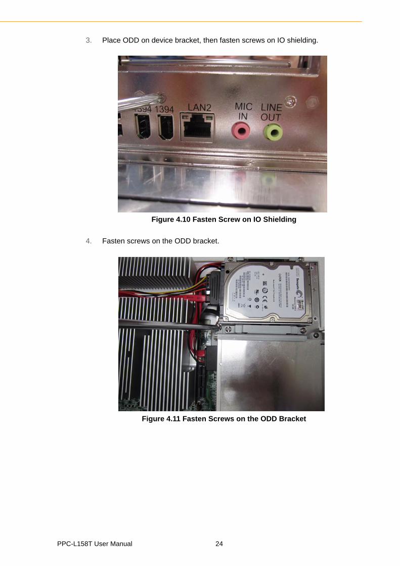
3. Place ODD on device bracket, then fasten screws on IO shielding.
Figure 4.10 Fasten Screw on IO Shielding
4. Fasten screws on the ODD bracket.
Figure 4.11 Fasten Screws on the ODD Bracket
PPC-L158T User Manual 24
Chapter 4
Hardw
areInstallation
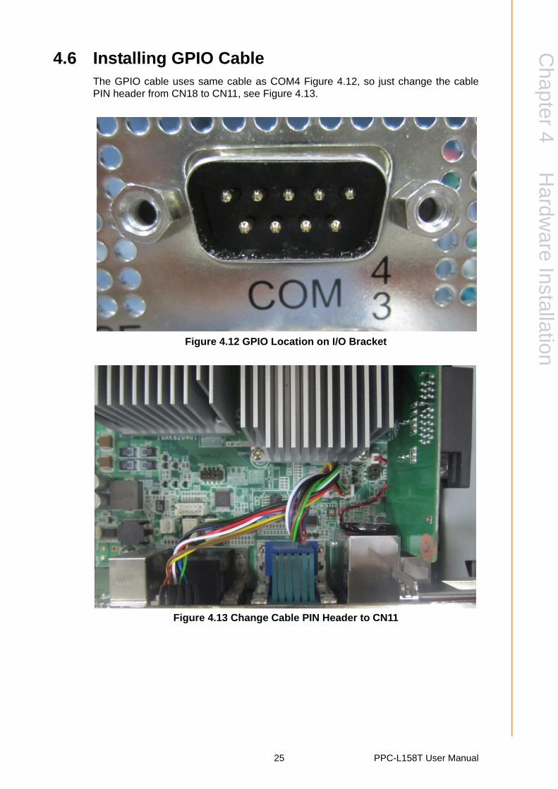
4.6 Installing GPIO CableThe GPIO cable uses same cable as COM4 Figure 4.12, so just change the cablePIN header from CN18 to CN11, see Figure 4.13.
Figure 4.12 GPIO Location on I/O Bracket
Figure 4.13 Change Cable PIN Header to CN11
25 PPC-L158T User Manual
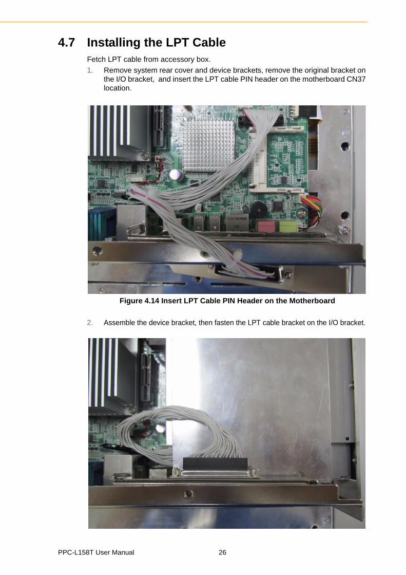
4.7 Installing the LPT CableFetch LPT cable from accessory box.
1. Remove system rear cover and device brackets, remove the original bracket on the I/O bracket, and insert the LPT cable PIN header on the motherboard CN37 location.
Figure 4.14 Insert LPT Cable PIN Header on the Motherboard
2. Assemble the device bracket, then fasten the LPT cable bracket on the I/O bracket.
PPC-L158T User Manual 26
Chapter 4
Hardw
areInstallation
Figure 4.15 Fix the LPT Cable on the I/O Bracket
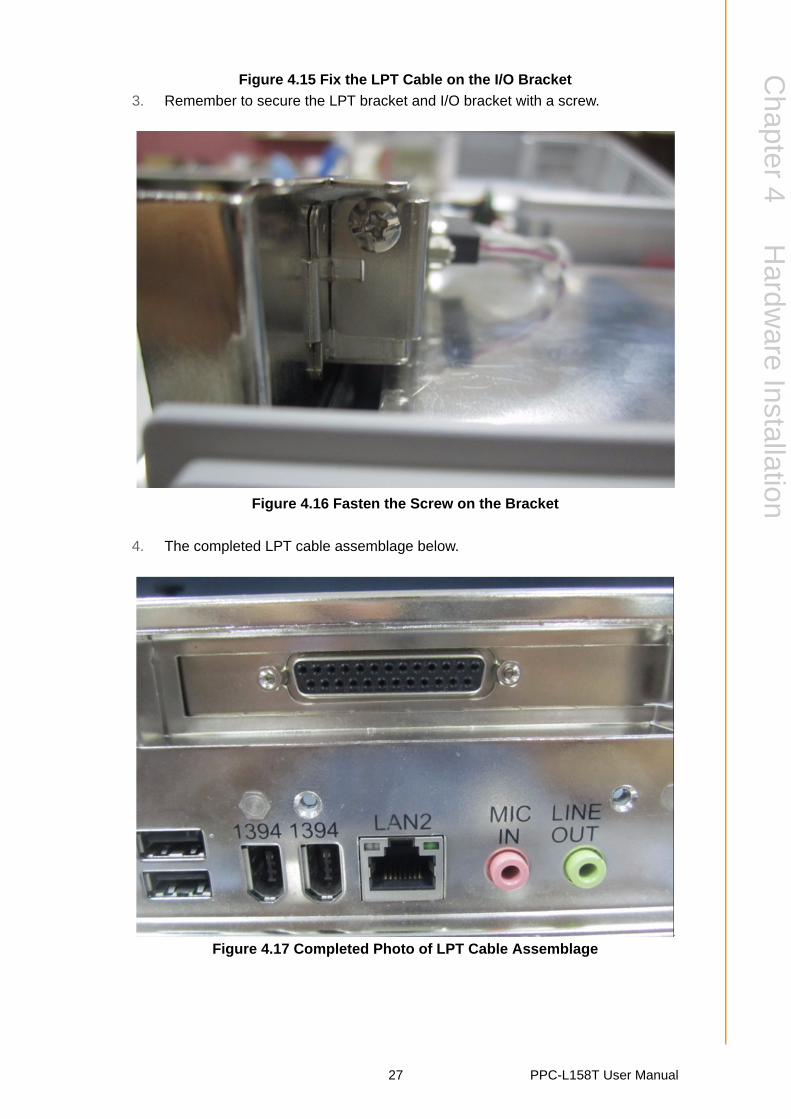
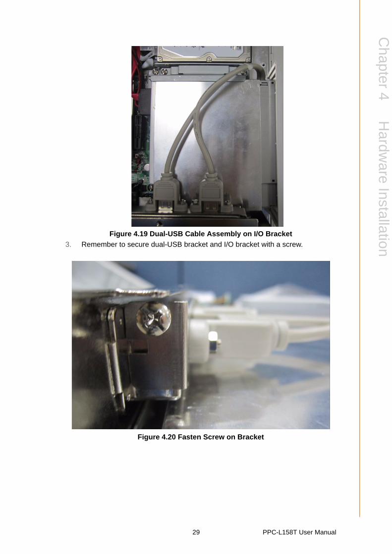
3. Remember to secure the LPT bracket and I/O bracket with a screw.
Figure 4.16 Fasten the Screw on the Bracket
4. The completed LPT cable assemblage below.
Figure 4.17 Completed Photo of LPT Cable Assemblage
27 PPC-L158T User Manual
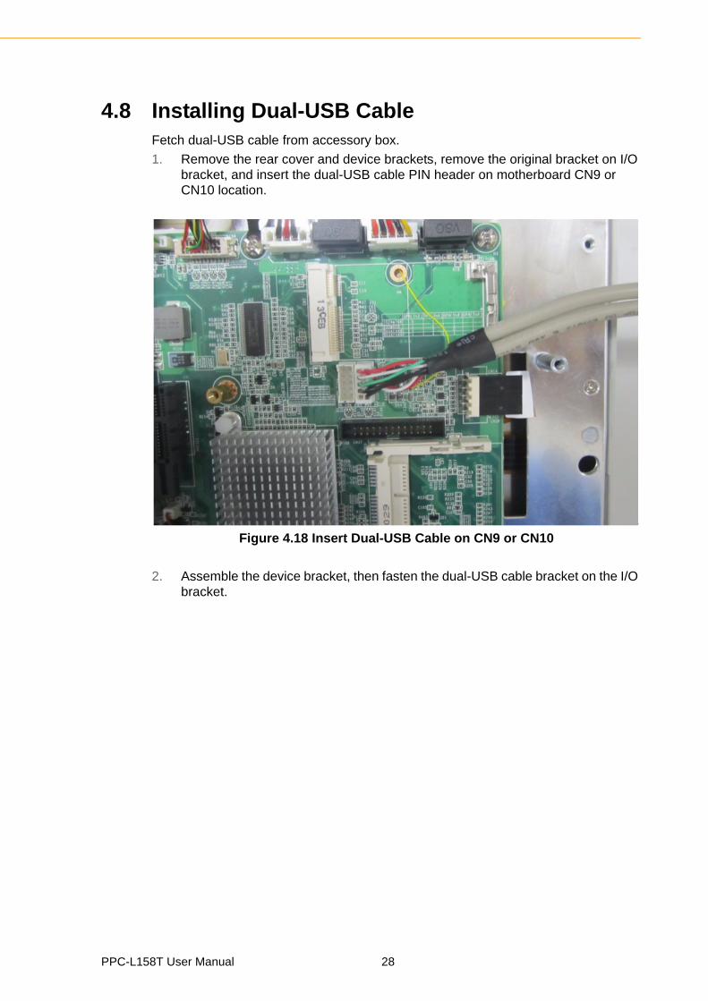
4.8 Installing Dual-USB CableFetch dual-USB cable from accessory box.
1. Remove the rear cover and device brackets, remove the original bracket on I/O bracket, and insert the dual-USB cable PIN header on motherboard CN9 or CN10 location.
Figure 4.18 Insert Dual-USB Cable on CN9 or CN10
2. Assemble the device bracket, then fasten the dual-USB cable bracket on the I/O bracket.
PPC-L158T User Manual 28
Chapter 4
Hardw
areInstallation
Figure 4.19 Dual-USB Cable Assembly on I/O Bracket
3. Remember to secure dual-USB bracket and I/O bracket with a screw.
Figure 4.20 Fasten Screw on Bracket
29 PPC-L158T User Manual
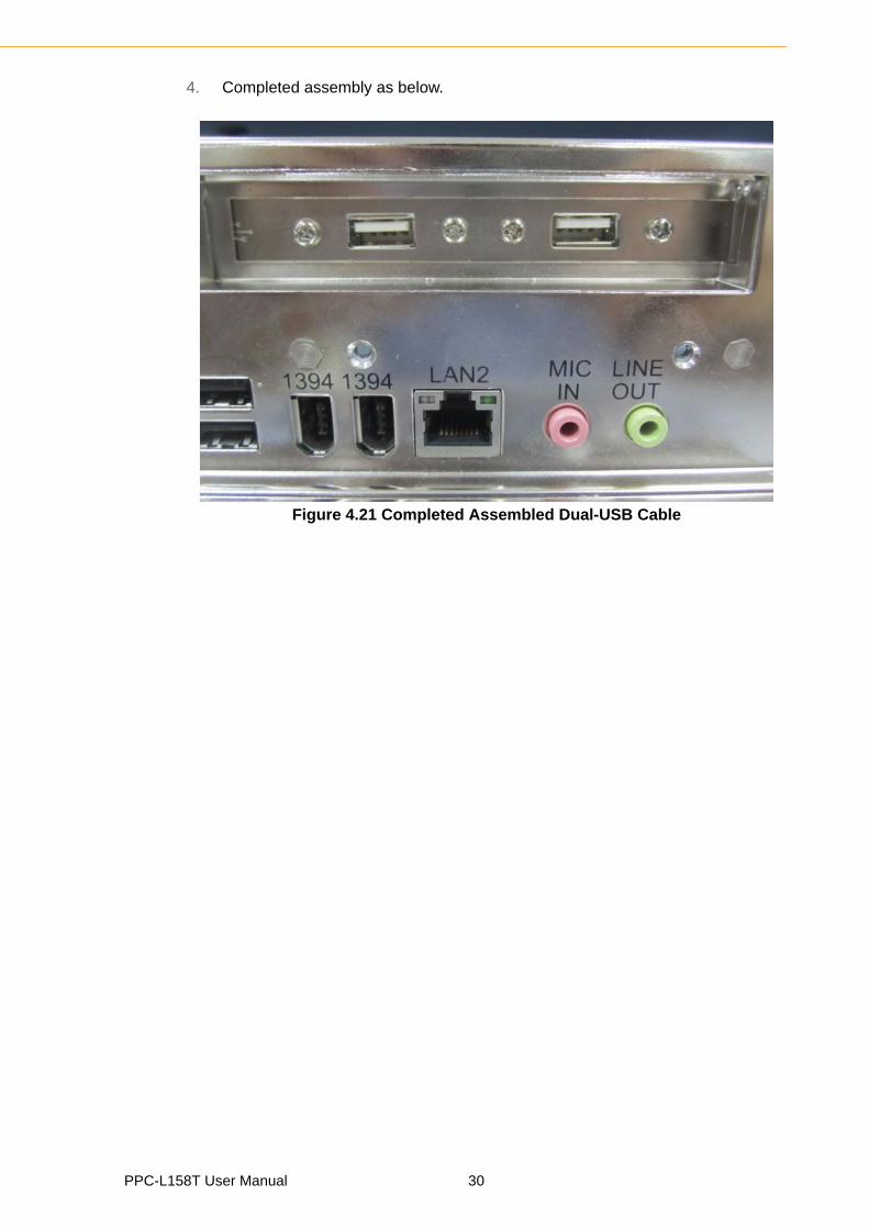
4. Completed assembly as below.
Figure 4.21 Completed Assembled Dual-USB Cable
PPC-L158T User Manual 30

Chapter 5
5 Jumpers and ConnectorsThis chapter gives information on setting jumpers and using the connectors on the PPC-L158T motherboard.Sections include:
Setting Jumpers
Jumpers and Connectors loca-tions
Connectors
5.1 Jumpers and ConnectorsThis chapter supplies more detailed information about the internal jumper settingsand an outline of the I/O ports available on the PPC-L158T.
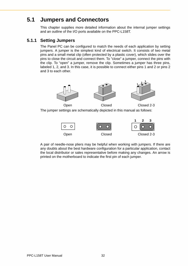
5.1.1 Setting JumpersThe Panel PC can be configured to match the needs of each application by settingjumpers. A jumper is the simplest kind of electrical switch. It consists of two metalpins and a small metal clip (often protected by a plastic cover), which slides over thepins to close the circuit and connect them. To ”close” a jumper, connect the pins withthe clip. To “open” a jumper, remove the clip. Sometimes a jumper has three pins,labeled 1, 2, and 3. In this case, it is possible to connect either pins 1 and 2 or pins 2and 3 to each other.
Open Closed Closed 2-3
The jumper settings are schematically depicted in this manual as follows:
Open Closed Closed 2-3
A pair of needle-nose pliers may be helpful when working with jumpers. If there areany doubts about the best hardware configuration for a particular application, contactthe local distributor or sales representative before making any changes. An arrow isprinted on the motherboard to indicate the first pin of each jumper.
1 2 3
PPC-L158T User Manual 32
Chapter 5
Jumpers
andC
onnectors
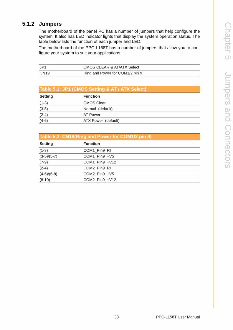
5.1.2 JumpersThe motherboard of the panel PC has a number of jumpers that help configure thesystem. It also has LED indicator lights that display the system operation status. Thetable below lists the function of each jumper and LED.
The motherboard of the PPC-L158T has a number of jumpers that allow you to con-figure your system to suit your applications.
JP1 CMOS CLEAR & AT/ATX Select
CN19 Ring and Power for COM1/2 pin 9
Table 5.1: JP1 (CMOS Setting & AT / ATX Select)
Setting Function
(1-3) CMOS Clear
(3-5) Normal (default)
(2-4) AT Power
(4-6) ATX Power (default)
Table 5.2: CN19(Ring and Power for COM1/2 pin 9)
Setting Function
(1-3) COM1_Pin9 RI
(3-5)/(5-7) COM1_Pin9 +V5
(7-9) COM1_Pin9 +V12
(2-4) COM2_Pin9 RI
(4-6)/(6-8) COM2_Pin9 +V5
(8-10) COM2_Pin9 +V12
33 PPC-L158T User Manual

5.1.3 Jumper and Connector Locations
Figure 5.1 Jumpers & Connectors on PPC-L158T Motherboard
CN34
CN25 CN31 CN30 CN11
CN12 CN13 CN5
CN3
CN4
CN2CN1
CN6
CN7
CN14
CN9/10
CN37
CN16
CN35
CN20
CN23
CN18
CN21
CN22
CN29
CN26/27
CN28 CN32 CN33
CN24
CN19
PPC-L158T User Manual 34
Chapter 5
Jumpers
andC
onnectors
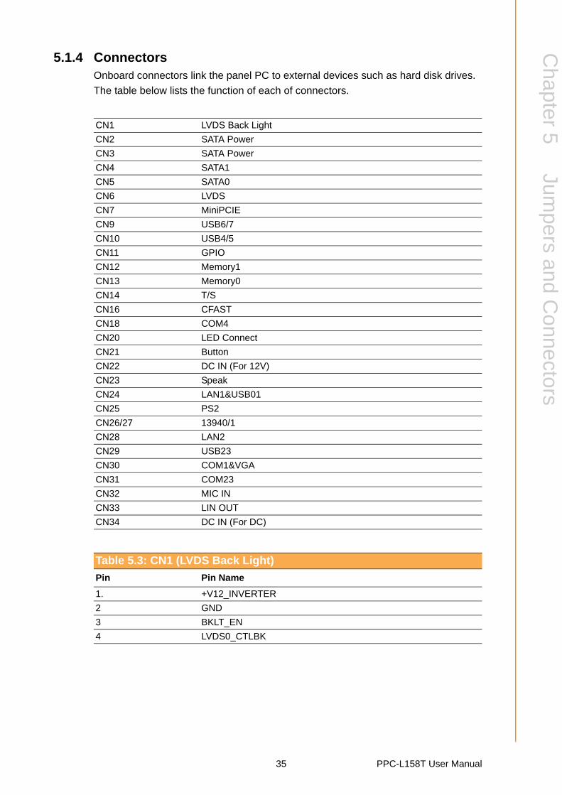
5.1.4 ConnectorsOnboard connectors link the panel PC to external devices such as hard disk drives.
The table below lists the function of each of connectors.
CN1 LVDS Back Light
CN2 SATA Power
CN3 SATA Power
CN4 SATA1
CN5 SATA0
CN6 LVDS
CN7 MiniPCIE
CN9 USB6/7
CN10 USB4/5
CN11 GPIO
CN12 Memory1
CN13 Memory0
CN14 T/S
CN16 CFAST
CN18 COM4
CN20 LED Connect
CN21 Button
CN22 DC IN (For 12V)
CN23 Speak
CN24 LAN1&USB01
CN25 PS2
CN26/27 13940/1
CN28 LAN2
CN29 USB23
CN30 COM1&VGA
CN31 COM23
CN32 MIC IN
CN33 LIN OUT
CN34 DC IN (For DC)
Table 5.3: CN1 (LVDS Back Light)
Pin Pin Name
1. +V12_INVERTER
2 GND
3 BKLT_EN
4 LVDS0_CTLBK
35 PPC-L158T User Manual
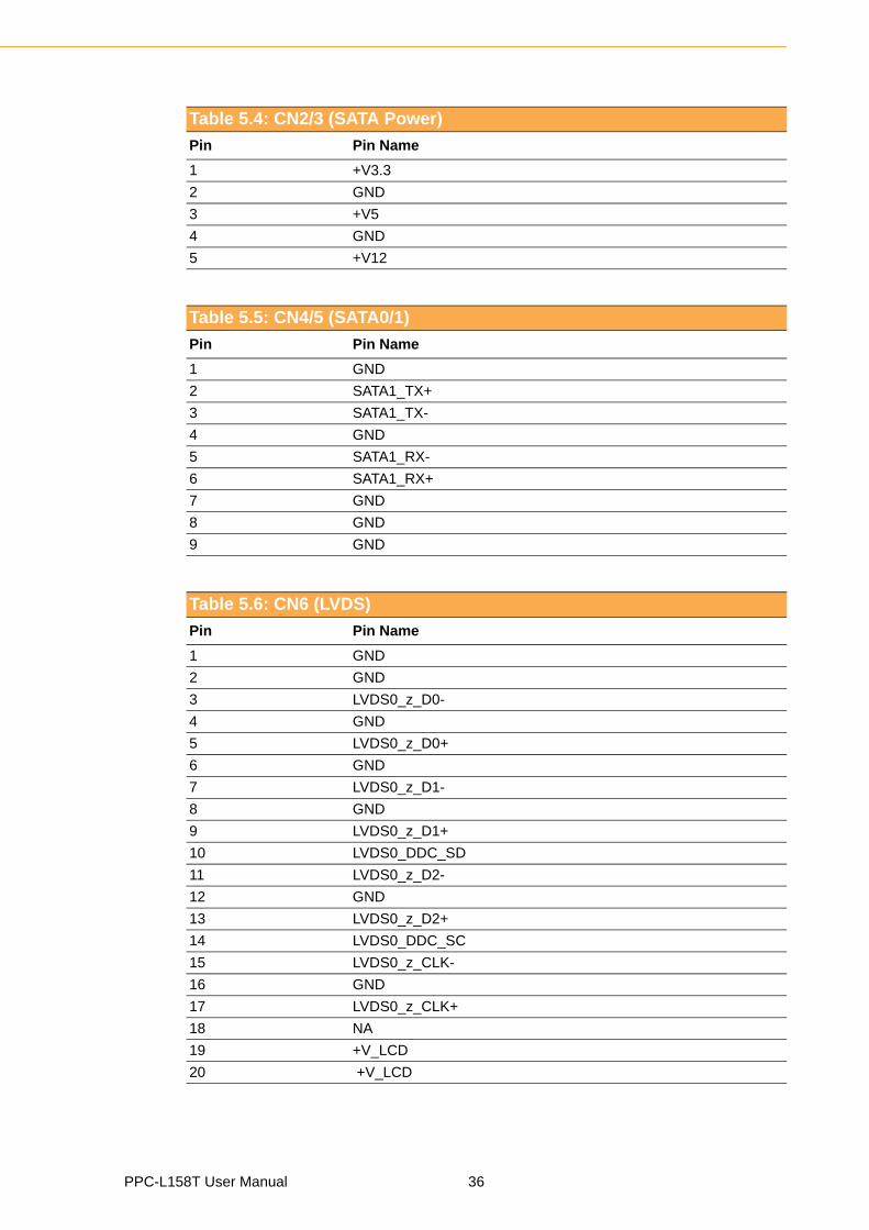
Table 5.4: CN2/3 (SATA Power)
Pin Pin Name
1 +V3.3
2 GND
3 +V5
4 GND
5 +V12
Table 5.5: CN4/5 (SATA0/1)
Pin Pin Name
1 GND
2 SATA1_TX+
3 SATA1_TX-
4 GND
5 SATA1_RX-
6 SATA1_RX+
7 GND
8 GND
9 GND
Table 5.6: CN6 (LVDS)
Pin Pin Name
1 GND
2 GND
3 LVDS0_z_D0-
4 GND
5 LVDS0_z_D0+
6 GND
7 LVDS0_z_D1-
8 GND
9 LVDS0_z_D1+
10 LVDS0_DDC_SD
11 LVDS0_z_D2-
12 GND
13 LVDS0_z_D2+
14 LVDS0_DDC_SC
15 LVDS0_z_CLK-
16 GND
17 LVDS0_z_CLK+
18 NA
19 +V_LCD
20 +V_LCD
PPC-L158T User Manual 36
Chapter 5
Jumpers
andC
onnectors
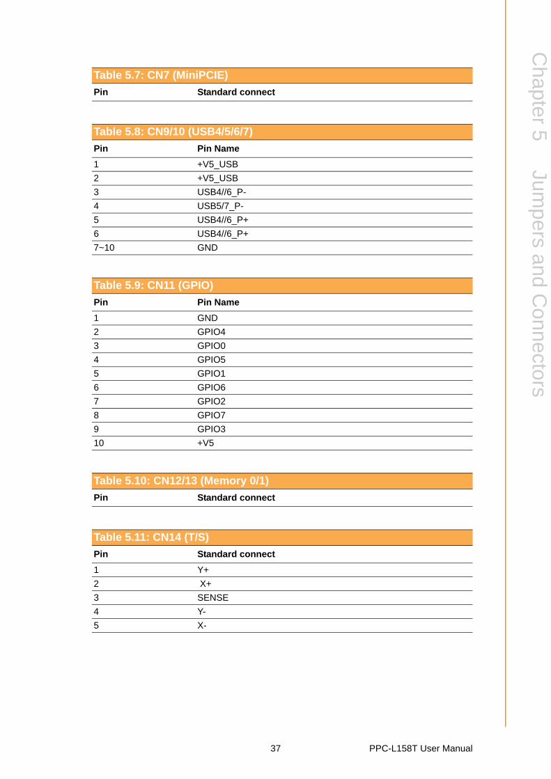
Table 5.7: CN7 (MiniPCIE)
Pin Standard connect
Table 5.8: CN9/10 (USB4/5/6/7)
Pin Pin Name
1 +V5_USB
2 +V5_USB
3 USB4//6_P-
4 USB5/7_P-
5 USB4//6_P+
6 USB4//6_P+
7~10 GND
Table 5.9: CN11 (GPIO)
Pin Pin Name
1 GND
2 GPIO4
3 GPIO0
4 GPIO5
5 GPIO1
6 GPIO6
7 GPIO2
8 GPIO7
9 GPIO3
10 +V5
Table 5.10: CN12/13 (Memory 0/1)
Pin Standard connect
Table 5.11: CN14 (T/S)
Pin Standard connect
1 Y+
2 X+
3 SENSE
4 Y-
5 X-
37 PPC-L158T User Manual
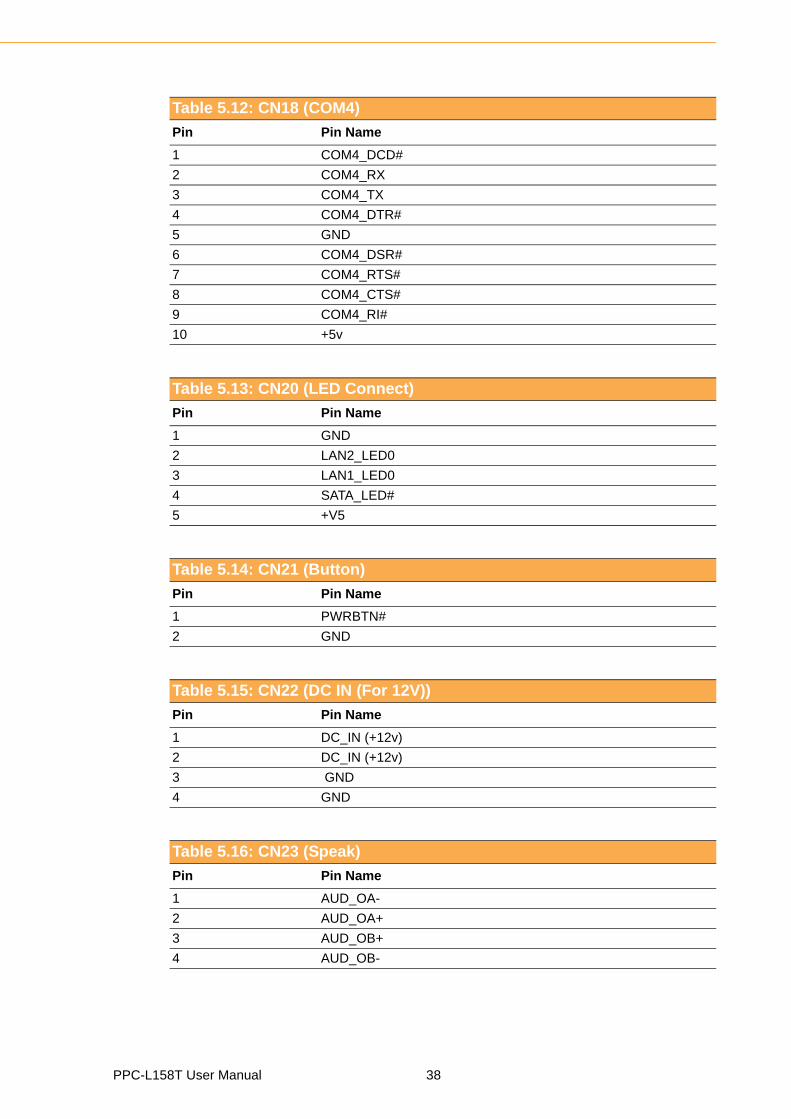
Table 5.12: CN18 (COM4)
Pin Pin Name
1 COM4_DCD#
2 COM4_RX
3 COM4_TX
4 COM4_DTR#
5 GND
6 COM4_DSR#
7 COM4_RTS#
8 COM4_CTS#
9 COM4_RI#
10 +5v
Table 5.13: CN20 (LED Connect)
Pin Pin Name
1 GND
2 LAN2_LED0
3 LAN1_LED0
4 SATA_LED#
5 +V5
Table 5.14: CN21 (Button)
Pin Pin Name
1 PWRBTN#
2 GND
Table 5.15: CN22 (DC IN (For 12V))
Pin Pin Name
1 DC_IN (+12v)
2 DC_IN (+12v)
3 GND
4 GND
Table 5.16: CN23 (Speak)
Pin Pin Name
1 AUD_OA-
2 AUD_OA+
3 AUD_OB+
4 AUD_OB-
PPC-L158T User Manual 38
Chapter 5
Jumpers
andC
onnectors
Table 5.17: CN24 (LAN1&USB01)Pin Standard connect
Table 5.18: CN25 (PS2)Pin Standard connect
Table 5.19: CN26/27(1394)
Pin Pin Name
1 +V12
2 GND
3 XTPBM
4 XTPBP
5 XTPAM
6 XTPAP
Table 5.20: CN28 (LAN2)
Pin Pin Name
1 MDI0+
2 MDI0-
3 MDI1+
4 MDI1-
5 VDC1
6 VDC2
7 MDI2+
8 MDI2-
9 MDI3+
10 MDI3-
11 +3.3V
12 ACT#
13 LINK1000#
14 LINK100#
Table 5.21: CN29 (USB23)
Pin Pin Name
1 +V5_USB
2 USB2_P-
3 USB2_P+
4 GND
5 +V5_USB
6 USB5/7_P-
7 USB4//6_P+
8~12 GND
39 PPC-L158T User Manual
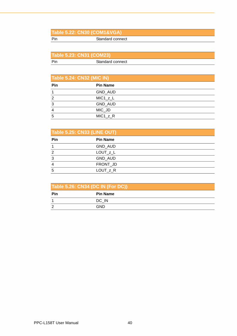
Table 5.22: CN30 (COM1&VGA)Pin Standard connect
Table 5.23: CN31 (COM23)Pin Standard connect
Table 5.24: CN32 (MIC IN)
Pin Pin Name
1 GND_AUD
2 MIC1_z_L
3 GND_AUD
4 MIC_JD
5 MIC1_z_R
Table 5.25: CN33 (LINE OUT)
Pin Pin Name
1 GND_AUD
2 LOUT_z_L
3 GND_AUD
4 FRONT_JD
5 LOUT_z_R
Table 5.26: CN34 (DC IN (For DC))
Pin Pin Name
1 DC_IN
2 GND
PPC-L158T User Manual 40
Chapter 6
6 Driver InstallationThis chapter gives information on installing drivers for the PPC-L158T.Sections include:
Driver Installation
Updating Drivers
6.1 IntroductionA Driver CD is supplied inside the accessory box. Customers may need to use anexternal USB CD-ROM related device to load the CD and install the drivers for thePPC-L158T.
6.1.1 Driver InstallationBefore installing the Ethernet driver, note the procedures below. It is necessary toknow which operating system is installed on the PPC-L158T. Then refer to the corre-sponding installation flow chart. Follow the steps described in the flow chart to com-plete the installation quickly. There are Drivers and documents included on the CD forthe chipset, LAN, Audio, Touchscreen, VGA, and USB, as well as a PDF copy of thisuser manual.
6.2 Updating Driver Search on the Advantech WebsiteFor further information about installing drivers on the PPC-L158T, and to accessdriver updates, troubleshooting guides and FAQ lists, visit the following webresources:
Advantech websites:
www.advantech.com
www.advantech.com.tw
Note! 1. The CD-ROM drive is designated as "D" throughout this chapter.2. <Enter> means pressing the "Enter" key on the keyboard.
PPC-L158T User Manual 42

Appendix A
A PCI Card and PCIe Size LimitsThis chapter details the size limits for PCI and PCIe cards that may be installed on the Panel PC moth-erboard.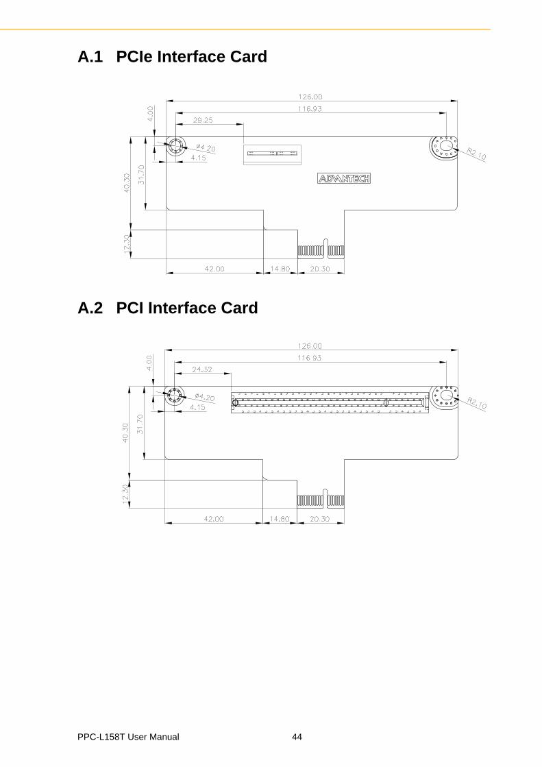
A.1 PCIe Interface Card
A.2 PCI Interface Card
PPC-L158T User Manual 44

www.advantech.comPlease verify specifications before quoting. This guide is intended for referencepurposes only.All product specifications are subject to change without notice.No part of this publication may be reproduced in any form or by any means,electronic, photocopying, recording or otherwise, without prior written permis-sion of the publisher.All brand and product names are trademarks or registered trademarks of theirrespective companies.© Advantech Co., Ltd. 2011

XXX-XXXX User Manual 46


![JP1 Version 11 - Hitachi Global [Agent] JP1/ITDM2 - Manager [Agent] Network monitoring server Windows JP1/ITDM2 - Manager JP1/ITDM2 - Manager [Network Monitor] Switch Internet Firewall](https://static.fdocuments.us/doc/165x107/5b1cd1327f8b9af2348c2109/jp1-version-11-hitachi-agent-jp1itdm2-manager-agent-network-monitoring.jpg)