PP-8802/8803 Package Contents - APLUS Système Automation
16
1 PP-8802/8803 Package Contents PP-8802 or PP-8803 Thermal Printer ( x 1) Paper Separator for 2” Thermal Paper Roll (x1) Thermal Paper Roll (x 1) USB Cable (x 1) Driver Download Information Guide (x 1) Power Adaptor (x 1) Power Cord (x 1) User Manual (x 1) Using poor-quality thermal papers which contain impurity particles, for instance, sands, or metals, will scratch the thermal paper head, and such a damage is not covered under the warranty. 19760900020 Ver. B0 http://www.posiflex.com PP-8802/8803 Thermal Printer User Manual
Transcript of PP-8802/8803 Package Contents - APLUS Système Automation

1
PP-8802/8803
Package Contents PP-8802 or PP-8803 Thermal Printer ( x 1)
Paper Separator for 2” Thermal Paper Roll
(x1)
Thermal Paper Roll (x 1)
USB Cable (x 1)
Driver Download Information Guide (x 1)
Power Adaptor (x 1)
Power Cord (x 1)
User Manual (x 1)
Using poor-quality thermal papers which contain impurity
particles, for instance, sands, or metals, will scratch the
thermal paper head, and such a damage is not covered
under the warranty.
19760900020 Ver. B0 http://www.posiflex.com
PP-8802/8803
Thermal Printer
User Manual
2
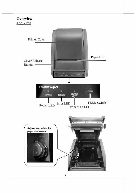
Overview Top View
Cover Release
Button
Paper Exit
Printer Cover
Power LED Error LED
Paper Out LED
FEED Switch
Adjustment wheel for
paper end sensor
3
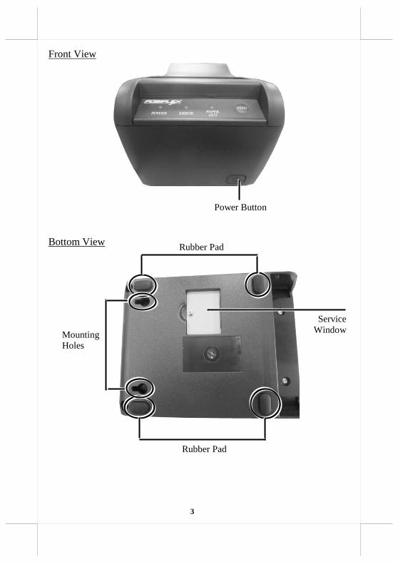
Front View
Bottom View
Rubber Pad
Mounting
Holes
Power Button
Rubber Pad
Service
Window

4
Views of I/O Interface
PP-8802
PP-8803
Cash drawer (CR) port
USB (Type B) Port
24 VDC-IN power jack
Serial DB-9 COM Port
LAN Port USB (Type B) Port
Cash drawer (CR) port
24 VDC-IN power jack
Serial DB-9 COM Port

5
Loading 2” or 3” Paper Rolls 1. Press down the cover release button to open the top cover.
2. Before installing 2-inch paper roll in the thermal printer, follow the
instructions below to properly install plastic pad spacer and the
separator. If you are using 3” paper roll for the printer, please
skip to next step.
The application of 58 mm width (2-inch) paper roll in this printer can be
achieved through adoption of an option spacing plate and an internal DIP
switch setting. Please contact the service team for the DIP switch setting.
Please refer to the middle picture above for the 58 mm paper spacing plate
with its flange at top edge showing out. Insert the noted corners of the
spacing plate into the 3 dents inside the paper roll compartment as arrowed
in the left picture above with point A goes in first. Then the 58 mm paper
roll sub compartment is formed as in the right picture above.
3. To load the thermal printer with
the 3-inch paper roll, make
sure the plastic pad is removed
from the printer compartment.
Then, carefully drop the
thermal paper roll inside the
paper roll compartment of the
printer as illustrated in the
figure.
6
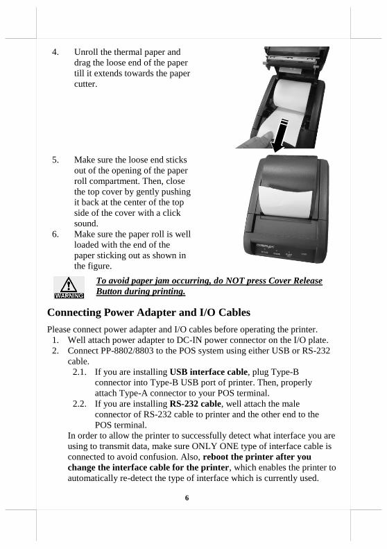
4. Unroll the thermal paper and
drag the loose end of the paper
till it extends towards the paper
cutter.
5. Make sure the loose end sticks
out of the opening of the paper
roll compartment. Then, close
the top cover by gently pushing
it back at the center of the top
side of the cover with a click
sound.
6. Make sure the paper roll is well
loaded with the end of the
paper sticking out as shown in
the figure.
To avoid paper jam occurring, do NOT press Cover Release
Button during printing.
Connecting Power Adapter and I/O Cables
Please connect power adapter and I/O cables before operating the printer. 1. Well attach power adapter to DC-IN power connector on the I/O plate.
2. Connect PP-8802/8803 to the POS system using either USB or RS-232
cable.
2.1. If you are installing USB interface cable, plug Type-B
connector into Type-B USB port of printer. Then, properly
attach Type-A connector to your POS terminal.
2.2. If you are installing RS-232 cable, well attach the male
connector of RS-232 cable to printer and the other end to the
POS terminal.
In order to allow the printer to successfully detect what interface you are
using to transmit data, make sure ONLY ONE type of interface cable is
connected to avoid confusion. Also, reboot the printer after you
change the interface cable for the printer, which enables the printer to
automatically re-detect the type of interface which is currently used.

7
Mounting PP-8802/8803 onto a Wall (Optional) Please follow the steps described below to mount POS printer on the wall
using wall-mount kits.
1. Define where the printer is mounted. Drill 2 holes about 3.15” or 80
mm apart. Each hole has to be at least 1/4” or 6.35 mm diameter
and at least 1 and 3/16” or 30 mm in depth.
2. After inserting two plastic anchors into the
holes you drilled in Step 1, slightly tap the
plastic anchors with a hammer until they are
fully inserted into the drilled holes.
3. Insert the screws into the plastic anchor,
screw them in but leave them sticking out
from the wall surface to mount the printer.
4. As shown in the figure, locate two holes on
bottom of PP-8802/8803. Then, carefully
hang the printer onto the wall using the
plastic anchors with screws.
5. To get more detailed information of wall mounting, please refer to
relative wall mounting installation guide.

8
Troubleshooting Paper Jams When it comes to the common printing problems, it is inevitable that you
might encounter the issue of paper jams at some point. The following steps are
provided to assist you in fixing the problem. Before proceeding, make sure that
your POS terminal is properly shut down.
1. To open the paper jams rescue compartment,
place your thumbs toward the center of the
compartment and then push the cover up in
the direction shown by the arrow.
2. In the paper jams rescue compartment, find
the adjustment wheel, which mainly allows
you to manually adjust the cutting position of
the cutter.
3. Keep turning the wheel in a clockwise
direction until the cutter is completely moved
back to its start position. You may observe
the cutter position through the gap between
paper jams rescue compartment and the
printer compartment.
4. Push down cover release button to test
whether the cover can be open. If the cover is
still stuck, please repeat step 3 until the cutter
position is set to the proper position and you
are able to open the cover.
5. Remove the jammed paper, reinstall the
paper roll, and then push back the cover to
close the paper jams rescue compartment.
Adjustment wheel

9
P.S. The adjustment wheel also can be turned by
using a screwdriver. The control hole is on the
right side of the compartment. Please refer to the
picture.
Restore Software Switch to Factory Default via Software Switch
Reset Software Switch Reset is the specially-designed function aimed to facilitate
the factory reset process. Please go through the following instructions to reset
your printer to factory settings using Software Switch Reset.
1. Power OFF printer.
2. Open the cover of printer.
3. Press Feed button three times while powering on the printer.
4. Close the cover of printer.
5. The printer will emit a beep sound and then print a test page
displaying software switch setting
6. Afterwards, the printer will restart by itself.
7. Ensure whether all the software switches are properly set to
factory default. The below figure shows software switch setting
for factory defaults.
Software switch number Pin Number
SW1 Pin 1 ~ 8 = OFF
SW2 Pin 1 ~ 8 = OFF
SW3 Pin 1 ~ 8 = OFF
SW4 Pin 1 ~ 8 = OFF
Screwdriver

10
Status LED Indicator
The below chart is provided to enumerate all the possible indicator
lights with their meanings for your reference.
LED Status Description
POWER LED Solid green System ON
Error LED Solid red Cover open
Flashing red Printer busy
Paper-out LED Solid red Out of Paper
Performing a Self-Test of the Printer 1. Power off the printer.
2. Press and hold the feed button of the printer.
3. Power on the printer. The printer will emit one short beep sound.
4. Release the feed button of the printer.
5. The printer performs a self-test and prints out the self-test result.
If the paper-out LED indicator still turns bright in red, press the feed
button of the printer to make the printer print the remaining self-test
result.
6. Release the feed button of the printer and then the paper-out LED
indicator does not light.
Entering the Hexadecimal Dump Mode To make the printer work in the hexadecimal dump mode, please go through
the following instructions.
1. Power off the printer.
2. Open the paper roll cover manually.
3. Press and hold the feed button of the printer.
4. Power on the printer. The printer will emit one short beep sound.
5. Release the feed button of the printer.
6. Close the paper roll cover manually.
7. The printer enters the hexadecimal dump mode and prints out the result
showing the “Hexadecimal Dump” message.

11
Cleaning Cleaning the Printer Case
Before cleaning the printer case, be sure to power off the printer, and wipe the
dirt off the printer case with a soft wiping cloth we provide.
Do NOT clean the product with alcohol, benzene, thinner, or
other such solvents. Doing so may damage or break the parts
made of plastic and rubber.
Cleaning the Thermal Head and the Platen Roller
In most cases, it is strongly recommended to regularly cleaning the thermal
head to maintain receipt print quality (about once every 3 months). While
using the printer, always ensure that dust particles are removed from paper
rolls and the gear by using the platen roller with a cotton swab moistened with
water. Then, power on the printer only after water has dried.
After printing, the thermal head and its surroundings
can be overheated. Make sure that it is completely
cooled down before cleaning it.
Do not damage the thermal head with your fingers or
any other hard object.
Troubleshooting Common Printer Problems The printer cannot print
Perform a self-test to check if printing is possible by following the steps
described below:
1. Close the paper cover.
2. While pressing the feed button, power on the printer. (Hold down the feed
button until printing starts.) The current printer status is printed.
3. Briefly press the feed button (less than one second) to continue the self-test.
The printer prints using the built-in character set. After the self-test printing,
the printer is reset and switches to standard mode.
LED Indicators are On/Flashing/Off
No lights is given by the LED indicators
Check whether the power supply cable is correctly connected to the printer and
the socket.
Error LED is on
Check whether the paper cover is closed.
Check if paper jam occurs or foreign substance enters the paper cutter.
When paper jams occur, refer to Troubleshooting Paper Jams section to
solve the problem.
The thermal head and its surroundings can be overheated, which may cause

12
printer malfunction. Printing starts again automatically when the thermal
head temperature falls.
Paper-out LED indicator is on
Check whether the paper roll is correctly installed.
Error LED indicator is flashing
Power off the printer; after 10 seconds, power it back on. If the error
LED indicator turns on again even after turning the power back on,
malfunction may occurs. Contact your dealer or Posiflex’ technical
service team.

13
Specifications PP-8802/8803
General
Printer Reliability
150 Km print length
Pulse Resistance
100 million pulses
NV Bit Image
Memory
12KB (max)
NV Graphics
256KB (max)
Receive Buffer
6KB
Printer Driver
Windows Driver(APD), UPOS(OPOS), Virtual COM
Driver, WEPOS
Software
Posiflex Uitlity (Android), PP-8800 Series Utility
(Windows Desktop), Development Tool, Monitoring
Tool
LED Indicators Green LED - On= Power
Red LED - Error and/or Paper Out
Sensors
Hood Lock (Microswitch)
Paper Near End (Microswitch)
Paper Out (Photo Sensor)
Overheat (Thermistor)
Cash Drawer Open (Microswitch in Cash drawer) Cash Drawer Port (CR
port)
2 drivers (CR port x1)
Power Consumption
2.5A max.
Power Source
AC adapter (24V DC)
Temperature Print quality assured: +5℃~ +40℃
Operating: 0℃~ +40℃
Non-operating: 0℃~ +50℃ (storage)
Relative Humidity
Operating: 20 ~ 85%, non-condensing 35%
Non-operating: 5% ~ 90%, non-condensing (thermal
paper excluded)
Standards and
Approvals
CE, FCC Dimensions (W x D x
H)
143 mm(H) x 148 mm(W) x 205 mm(D)
Weight
1,200g
Color
Black / White / Ivory
Options
Wall Mounting Kits
14
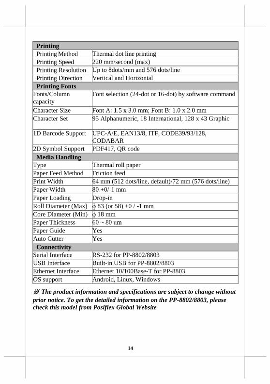
Printing
Printing Method Thermal dot line printing
Printing Speed 220 mm/second (max)
Printing Resolution Up to 8dots/mm and 576 dots/line
Printing Direction Vertical and Horizontal
Printing Fonts
Fonts/Column
capacity
Font selection (24-dot or 16-dot) by software command
Character Size Font A: 1.5 x 3.0 mm; Font B: 1.0 x 2.0 mm
Character Set
95 Alphanumeric, 18 International, 128 x 43 Graphic
1D Barcode Support UPC-A/E, EAN13/8, ITF, CODE39/93/128,
CODABAR
2D Symbol Support PDF417, QR code
Media Handling
Type Thermal roll paper
Paper Feed Method
Friction feed
Print Width
64 mm (512 dots/line, default)/72 mm (576 dots/line)
Paper Width
80 +0/-1 mm
Paper Loading
Drop-in
Roll Diameter (Max)
ɸ 83 (or 58) +0 / -1 mm
Core Diameter (Min)
ɸ 18 mm
Paper Thickness
60 ~ 80 um
Paper Guide
Yes
Auto Cutter
Yes
Connectivity
Serial Interface
RS-232 for PP-8802/8803
USB Interface
Built-in USB for PP-8802/8803
for Ethernet Interface Ethernet 10/100Base-T for PP-8803
OS support
Android, Linux, Windows
※ The product information and specifications are subject to change without
prior notice. To get the detailed information on the PP-8802/8803, please
check this model from Posiflex Global Website

15
<MEMO>

16
<MEMO>