PowerPoint Presentation€¦ · PPT file · Web view2013-04-29 · fixing or changing equipment...
21
Saudi Aramco Internship Student name:Ali Al-Marri 200800905
Transcript of PowerPoint Presentation€¦ · PPT file · Web view2013-04-29 · fixing or changing equipment...

Saudi Aramco Internship
Student name:Ali Al-Marri200800905
Outline
• Introduction• Gas Oil Separation(GOSP)• Maintenance Division • Ghawar Engineering Division, Inspection • Production Engineering Division
Introduction
• Saudi Aramco Start• History• Ghawar• Oil rate• Improvement
Introduction
• Saudi Aramco Start• History• Ghawar• Oil rate• Improvement
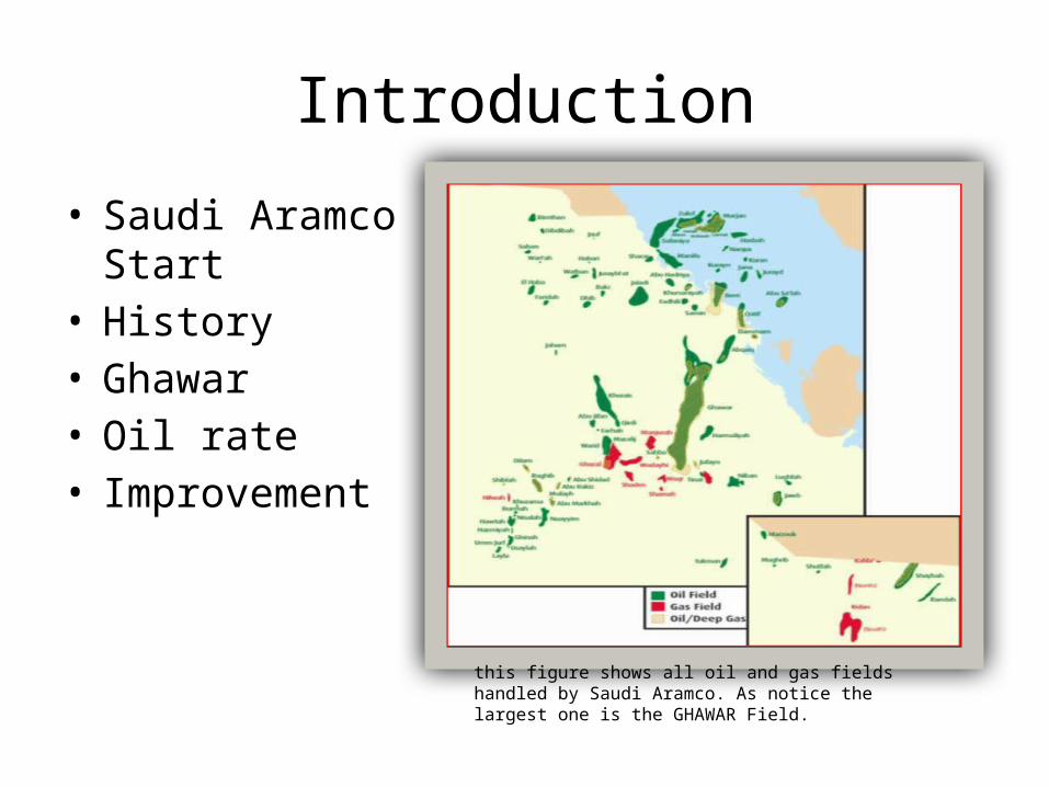
this figure shows all oil and gas fields handled by Saudi Aramco. As notice the largest one is the GHAWAR Field.
Gas Oil Separation(GOSP)
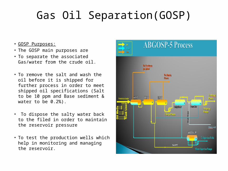
• GOSP Purposes:• The GOSP main purposes are • To separate the associated Gas/water from
the crude oil.
• To remove the salt and wash the oil before it is shipped for further process in order to meet shipped oil specifications (Salt to be 10 ppm and Base sediment & water to be 0.2%).
• To dispose the salty water back to the filed in order to maintain the reservoir pressure
• To test the production wells which help in monitoring and managing the reservoir.
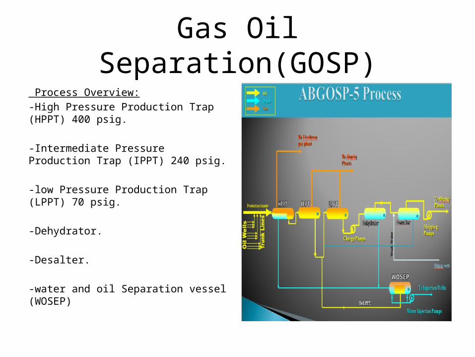
Gas Oil Separation(GOSP) Process Overview:-High Pressure Production Trap (HPPT) 400 psig.
-Intermediate Pressure Production Trap (IPPT) 240 psig.
-low Pressure Production Trap (LPPT) 70 psig.
-Dehydrator.
-Desalter.
-water and oil Separation vessel (WOSEP)
Maintenance Division
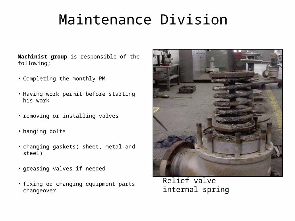
Machinist group is responsible of the following;
• Completing the monthly PM
• Having work permit before starting his work
• removing or installing valves
• hanging bolts
• changing gaskets( sheet, metal and steel)
• greasing valves if needed
• fixing or changing equipment parts changeover
Relief valve internal spring
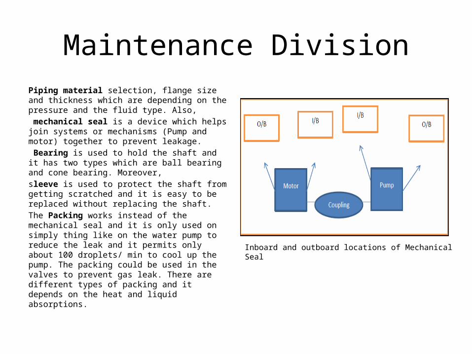
Maintenance DivisionPiping material selection, flange size and thickness which are depending on the pressure and the fluid type. Also, mechanical seal is a device which helps join systems or mechanisms (Pump and motor) together to prevent leakage. Bearing is used to hold the shaft and it has two types which are ball bearing and cone bearing. Moreover, sleeve is used to protect the shaft from getting scratched and it is easy to be replaced without replacing the shaft. The Packing works instead of the mechanical seal and it is only used on simply thing like on the water pump to reduce the leak and it permits only about 100 droplets/ min to cool up the pump. The packing could be used in the valves to prevent gas leak. There are different types of packing and it depends on the heat and liquid absorptions.
Inboard and outboard locations of Mechanical Seal
Maintenance Division• Instruments group is responsible of the following; • Completing the monthly PM • Having work permit before starting his work • Every equipment uses air or send signal to the control room
• Learned while with instrumentation Technician; • Every level switch has a vent • Level switch work mechanism; the float rise up when the level rise and it has a magnet at the end of its
rod. When the magnet touches the rod of the level switch, the circuit is closed. Then, the alarm initiated in the control. If high high level is reached, signal is sent to ESD to shut down.
• TCV; temperature control valve can be controlled manually from box called pneumatic control. By indicating the desired temperature, the valve will open and close to achieve that temperature by cooling the oil or not.
• JCV; power control valve is used to control the power of the compressor by controlling the flow on the compressor using some calculation inside the control room to find the needed power for the compressor
• To do test on valves using air during shut down two types of air pump are used; Air pump and Hydraulic pump.
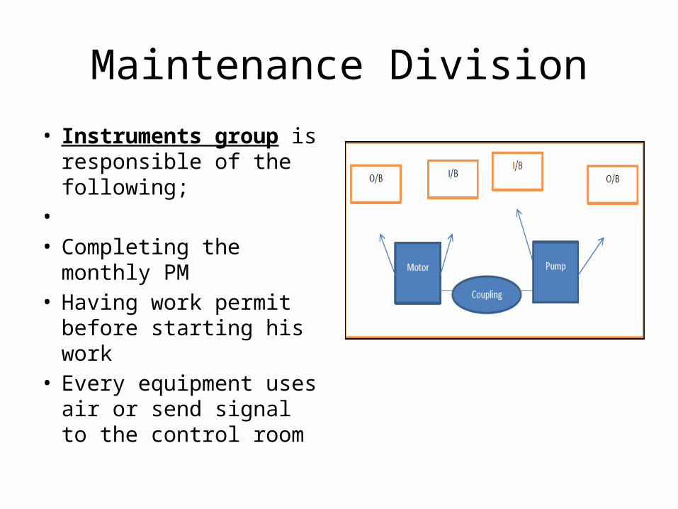
Maintenance Division• Instruments group is
responsible of the following;
• • Completing the monthly
PM • Having work permit before
starting his work • Every equipment uses air
or send signal to the control room
Maintenance Division
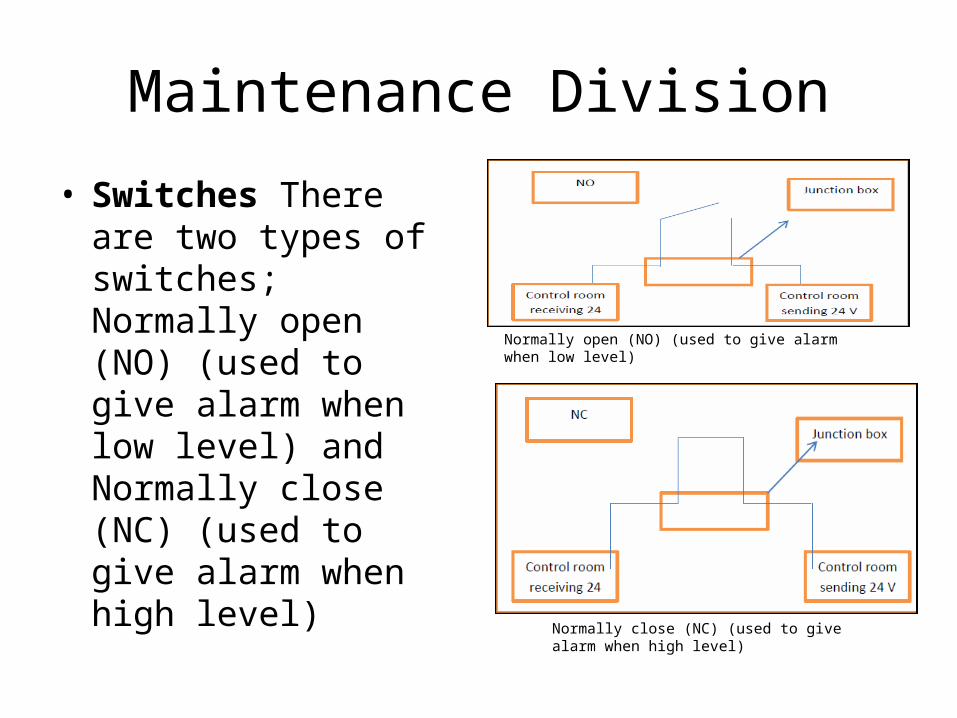
• Switches There are two types of switches; Normally open (NO) (used to give alarm when low level) and Normally close (NC) (used to give alarm when high level)
Normally open (NO) (used to give alarm when low level)
Normally close (NC) (used to give alarm when high level)
Ghawar Engineering Division, Inspection
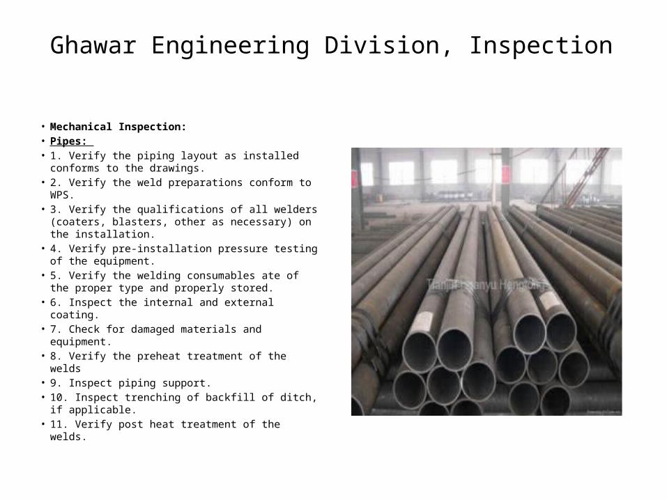
• Mechanical Inspection: • Pipes: • 1. Verify the piping layout as installed conforms
to the drawings. • 2. Verify the weld preparations conform to WPS. • 3. Verify the qualifications of all welders (coaters,
blasters, other as necessary) on the installation. • 4. Verify pre-installation pressure testing of the
equipment. • 5. Verify the welding consumables ate of the
proper type and properly stored. • 6. Inspect the internal and external coating. • 7. Check for damaged materials and equipment. • 8. Verify the preheat treatment of the welds • 9. Inspect piping support. • 10. Inspect trenching of backfill of ditch, if
applicable. • 11. Verify post heat treatment of the welds.
Ghawar Engineering Division, Inspection
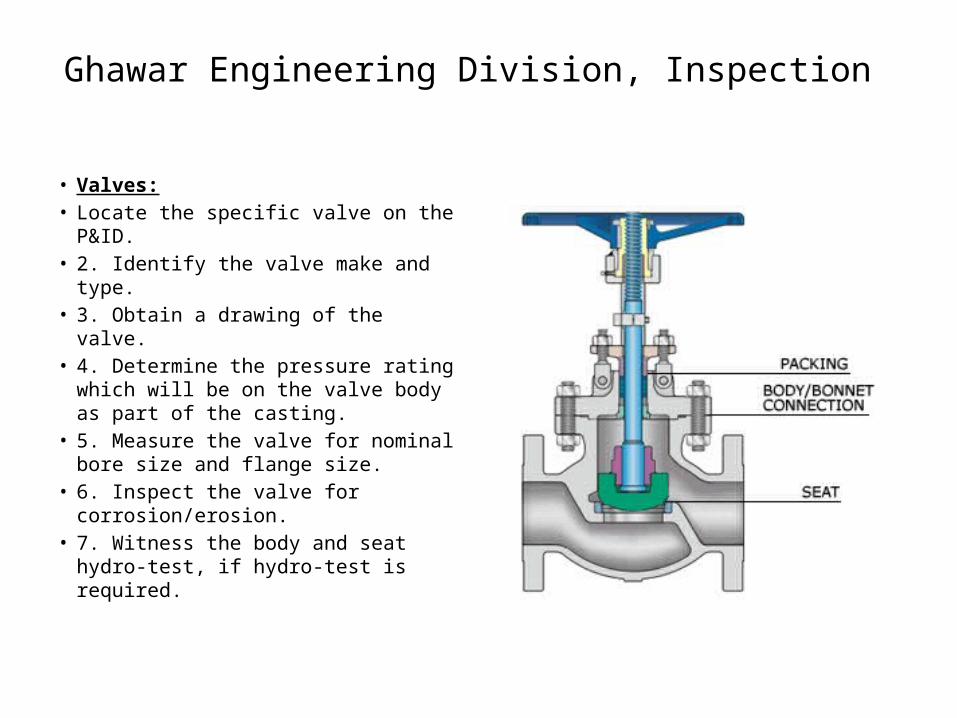
• Valves:• Locate the specific valve on the
P&ID. • 2. Identify the valve make and type. • 3. Obtain a drawing of the valve. • 4. Determine the pressure rating
which will be on the valve body as part of the casting.
• 5. Measure the valve for nominal bore size and flange size.
• 6. Inspect the valve for corrosion/erosion.
• 7. Witness the body and seat hydro-test, if hydro-test is required.
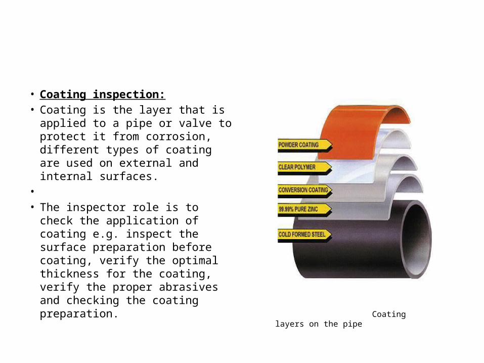
• Coating inspection:• Coating is the layer that is applied
to a pipe or valve to protect it from corrosion, different types of coating are used on external and internal surfaces.
• • The inspector role is to check the
application of coating e.g. inspect the surface preparation before coating, verify the optimal thickness for the coating, verify the proper abrasives and checking the coating preparation. Coating layers on the pipe
Ghawar Engineering Division, Inspection
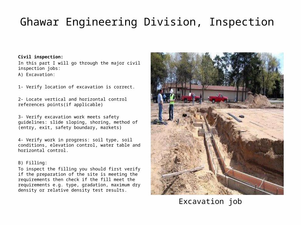
Civil inspection:In this part I will go through the major civil inspection jobs: A) Excavation: 1- Verify location of excavation is correct. 2- Locate vertical and horizontal control references points(if applicable)
3- Verify excavation work meets safety guidelines: slide sloping, shoring, method of (entry, exit, safety boundary, markets)
4- Verify work in progress: soil type, soil conditions, elevation control, water table and horizontal control.
B) Filling: To inspect the filling you should first verify if the preparation of the site is meeting the requirements then check if the fill meet the requirements e.g. type, gradation, maximum dry density or relative density test results.
Excavation job
Ghawar Engineering Division, Inspection
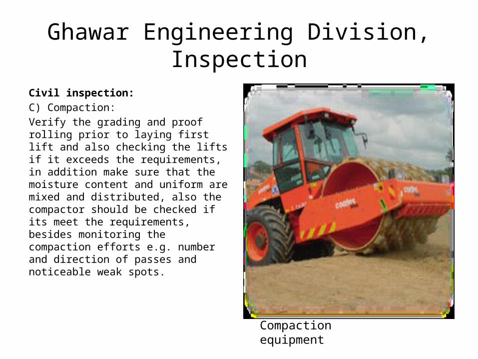
Civil inspection:C) Compaction:Verify the grading and proof rolling prior to laying first lift and also checking the lifts if it exceeds the requirements, in addition make sure that the moisture content and uniform are mixed and distributed, also the compactor should be checked if its meet the requirements, besides monitoring the compaction efforts e.g. number and direction of passes and noticeable weak spots.
Compaction equipment
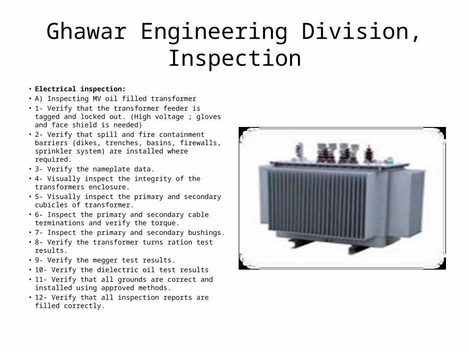
Ghawar Engineering Division, Inspection• Electrical inspection: • A) Inspecting MV oil filled transformer • 1- Verify that the transformer feeder is tagged and
locked out. (High voltage ; gloves and face shield is needed)
• 2- Verify that spill and fire containment barriers (dikes, trenches, basins, firewalls, sprinkler system) are installed where required.
• 3- Verify the nameplate data. • 4- Visually inspect the integrity of the transformers
enclosure. • 5- Visually inspect the primary and secondary cubicles of
transformer. • 6- Inspect the primary and secondary cable terminations
and verify the torque. • 7- Inspect the primary and secondary bushings. • 8- Verify the transformer turns ration test results. • 9- Verify the megger test results. • 10- Verify the dielectric oil test results • 11- Verify that all grounds are correct and installed using
approved methods. • 12- Verify that all inspection reports are filled correctly.
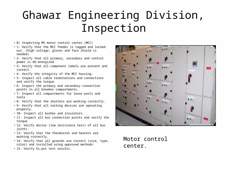
Ghawar Engineering Division, Inspection• B) Inspecting MV motor control center (MCC) • 1- Verify that the MCC feeder is tagged and locked out.
(High voltage; gloves and face shield is needed). • 2- Verify that all primary, secondary and control power is
de-energized. • 3- Verify that all component labels are present and correct. • 4- Verify the integrity of the MCC housing. • 5- Inspect all cable terminations and connections and verify
the torque. • 6- Inspect the primary and secondary connection points in
all breaker compartments. • 7- Inspect all compartments for loose parts and tools • 8- Verify that the shutters are working correctly. • 9- Verify that all racking devices are operating properly. • 10- Inspect all bushes and insulators. • 11- Inspect all bus connection points and verify the torque. • 12- Verify doctor (low resistance test) of all bus joints. • 13- Verify that the thermostat and heaters are working
correctly. • 14- Verify that all grounds are correct (size, type, color) and
installed using approved methods. • 15- Verify hi-pot test results.
Motor control center.
Ghawar Engineering Division, Inspection
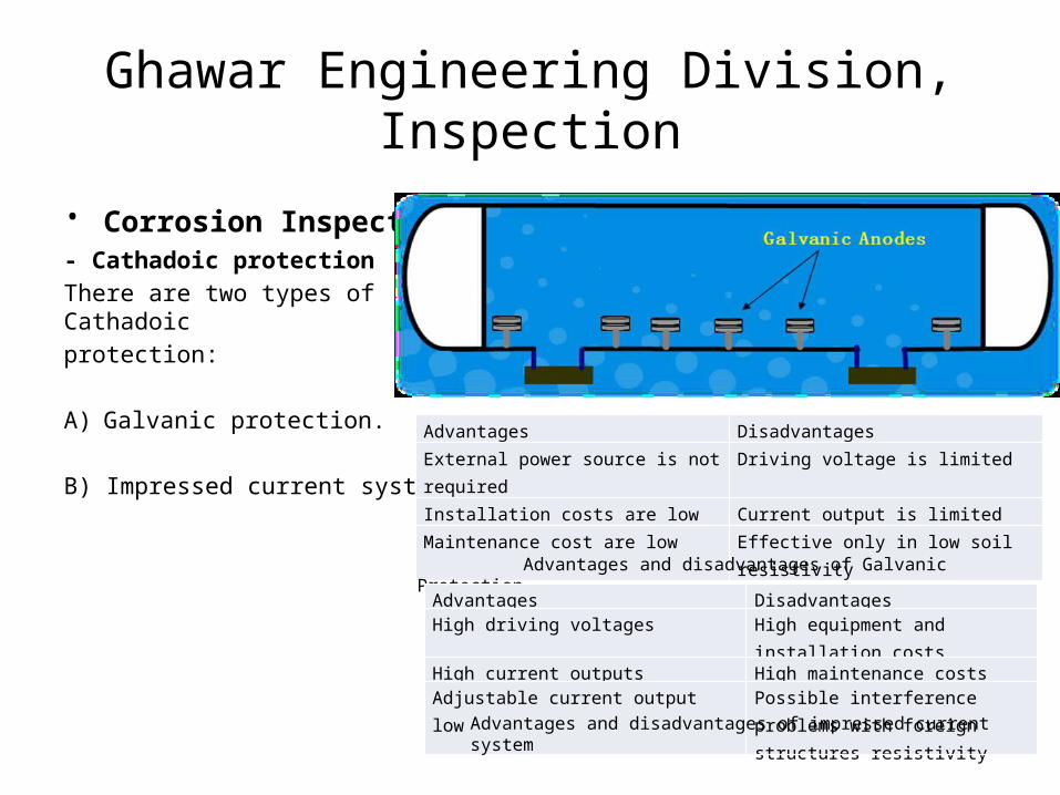
• Corrosion Inspection: - Cathadoic protection There are two types of Cathadoic protection:
A) Galvanic protection.
B) Impressed current system.
• Ghawar Engineering Division, Inspection
Advantages Disadvantages External power source is not required Driving voltage is limited Installation costs are low Current output is limited Maintenance cost are low Effective only in low soil resistivity
Advantages and disadvantages of Galvanic Protection
Advantages Disadvantages High driving voltages High equipment and installation costs High current outputs High maintenance costs Adjustable current output low Possible interference problems with
foreign structures resistivity
Advantages and disadvantages of impressed current system
ROAD OIL PLANT MOTHBALLING• PROCEDURE:• Management has decided to close Road Oil Plant (ROP)
permanently. Consequently, mothballing Road Oil Plant (ROP) is required to ensure that the required reliability and integrity of plant machinery and stationary equipment will be maintained in good condition at a minimum cost.
• • Since NGED/PEU is responsible to issue the mothballing
procedure, I had a great opportunity to work with them in preparing the procedure. Below is what we have recommended in order to safely mothball Abqaiq Road Oil Plant (ROP):
• Conduct NORM survey at ROP before opening the vessels. • Use Nitrogen as mothballing media and maintain all
pressure vessels at 50 psig.• Fire watch should be present during all cutting and
welding jobs. • Expedite conducting the mothballing immediately
following the ROP shutdown to avoid corrosion activities due to prolong liquid stagnation.
•
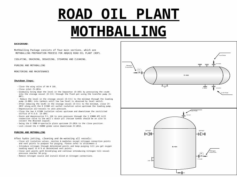
ROAD OIL PLANT MOTHBALLINGBACKGROUND: Mothballing Package consists of four main sections, which are MOTHBALLING PREPARATION PROCESS FOR ABQAIQ ROAD OIL PLANT (ROP).
ISOLATING, DRAINING, DEGASSING, STEAMING AND CLEANING.
PURGING AND MOTHBALLING
MONITORING AND MAINTENANCE
Shutdown Steps:
– Close the wing valve of AW # 166.– Close inlet ZV-201A.– Gradually bring down the level in the Separator (D-103) by pressuring the crude into the storage vessel
(D-111) through the flash pot using the transfer pump (G-007).– Reduce the level in the storage vessel (D-111) to the minimum through the loading pump (G-006) into
tankers until low low level is observed by level switch.– After reducing the level in the storage vessel (D-111) to the minimum, close ZV-201F along with the
8”X150# oil outlet isolation valve upstream the loading pump.– Depressurize all vessels to zero pressure.– Close the two 4”X150# isolation valves upstream and downstream the restricted orifice of K.O.D. (D-104).– Drain and depressurize F/L 166 to zero pressure through the 3”X3000 API kill connection valve to the
well’s drain pit (Vacuum tanker should be on site to collect the drained liquid).– Swing the 6”X900 # spectacle plate upstream ZV-201A to the close position.– Lock closed the 4”X600# globe valve downstream ZV-201A.
PURGING AND MOTHBALLING After hydro jetting, cleaning and de-watering all vessels:
– Close all isolation valves, nozzles & manholes except nitrogen connection points and vent points to prepare for purging. Please refer to attachment-2
– Introduce nitrogen through determined points and keep purging till you get oxygen reading equal to 0 % at determined vent points.
– Close vent points with blind/plug and continue introducing nitrogen till vessel pressure reaches 50 psig.– Remove nitrogen source and install blind on nitrogen connections.