powerMELA - Baumueller
6
be in motion powerMELA ® Permanent Magnet Synchronous Motors with Integrated Power Inverters
Transcript of powerMELA - Baumueller

be in motion
powerMELA®
Permanent Magnet Synchronous Motors
with Integrated Power Inverters
powerMELA®
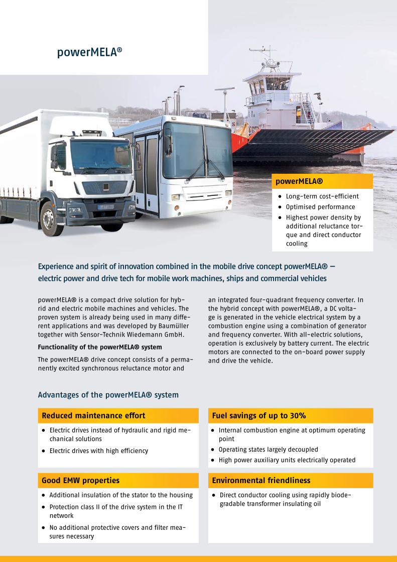
powerMELA® is a compact drive solution for hyb-rid and electric mobile machines and vehicles. The proven system is already being used in many diffe-rent applications and was developed by Baumüller together with Sensor-Technik Wiedemann GmbH.
Functionality of the powerMELA® system
The powerMELA® drive concept consists of a perma-nently excited synchronous reluctance motor and
an integrated four-quadrant frequency converter. In the hybrid concept with powerMELA®, a DC volta-ge is generated in the vehicle electrical system by a combustion engine using a combination of generator and frequency converter. With all-electric solutions, operation is exclusively by battery current. The electric motors are connected to the on-board power supply and drive the vehicle.
Experience and spirit of innovation combined in the mobile drive concept powerMELA® —
electric power and drive tech for mobile work machines, ships and commercial vehicles
Reduced maintenance effort Fuel savings of up to 30%
Advantages of the powerMELA® system
Electric drives instead of hydraulic and rigid me-chanical solutions
Electric drives with high efficiency
Internal combustion engine at optimum operating point
Operating states largely decoupled
High power auxiliary units electrically operated
Good EMW properties
Additional insulation of the stator to the housing
Protection class II of the drive system in the IT network
No additional protective covers and filter mea-sures necessary
Environmental friendliness
Direct conductor cooling using rapidly biode-gradable transformer insulating oil
Long-term cost-efficient
Optimised performance
Highest power density by additional reluctance tor-que and direct conductor cooling
powerMELA®

powerMELA-C 132/50, powerMELA-C 132/80, powerMELA-C 132/140
The powerMELA-C series is a family of permanent magnet synchronous electric machines with integrated power
inverters. They were developed specifically for mobile working machines, for use in both the main drive and
auxiliary drives. The machines are liquid cooled and designed for 4 quadrant operation. The desired values for
torque, voltage and speed control can be set over CAN bus.
Technical data
Size (rotor height/power) [mm]/[kW] 132/50 132/80 132/140
Phases 1 x 3 1 x 3 2 x 3
Earthing System IT IT ITStand-alone operation only,
not connected to the grid
Protection class IP6K9K IP6K9K IP6K9K *
Construction flange flange flange
Operation data
Nominal power (motor shaft) [kW] 50 80 140 S9
Maximum power [kW] 75 88 154 for max. 15 seconds
Nominal voltage DC [V] 650 650 650 other voltages on request
Operating voltage range DC [V] 400 ... 695 400 ... 695 400 ... 695
Temporary overvoltage DC [V] < 730 < 730 < 730for max. 5 seconds,
according to DIN EN 60664
Nominal current DC [A] 85 146 256 while engine operating as a motor
Nominal torque [Nm] 160 250 445
Maximum torque [Nm] 245 338 610
Nominal speed [min-1] 3000 3000 3000
Maximum speed [min-1] 6000 6000 6000
Voltage supply DC [V] 9 ... 32 9 ... 32 9 ... 32
Mechanical data
Length without shaft L1 [mm] 379 379 513
Length with shaft L2 [mm] 450 450 584 other dimensions on request
Shaft diameter d1 [mm] 35 35 35DIN5480-W35 x 2 x 30 x 16 x 9 g –
other dimensions on request
Weight [kg] 90 90 147
Rotor inertia [kgm2] 0.0493 0.0493 0.08
Max. cooling fluid temperature [°C] 60 60 60 Transformer oil 50 l/min
Cooling connector amount 2 2 2 M26 x 1,5
Power connector amount 2 2 2 70 mm2 with 8 mm cable lug
Communication connector 19 pole 19 pole 19 pole 2x CAN; I/O
Maximum impulse withstand
voltage[V] 4000 4000 4000
Maximum altitude of use m a.s.l. 5000 5000 5000
Please note: Isolation monitoring is required. DC link discharge time is maximum 60 seconds.
www.baumueller.com
* Unmounted: drive shaft / flange IP65, Communication Connector IP67

Torque / Power (S9/Overload)
50 kW
80 kW
0 1000 2000 3000 4000 5000 6000
Speed [min-1]
650
600
550
500
450
400
350
300
250
200
150
100
50
0
Torq
ue
[Nm
]
180
160
140
120
100
80
60
40
20
0
Pow
er [
kW]
Nominal torqueMaximum torqueNominal powerMaximum power
0 1000 2000 3000 4000 5000 6000
Speed [min-1]
400
350
300
250
200
150
100
50
0
Torq
ue
[Nm
]
100
90
80
70
60
50
40
30
20
10
0
Pow
er [
kW]
Nominal torqueMaximum torqueNominal powerMaximum power
0 1000 2000 3000 4000 5000 6000
Speed [min-1]
400
350
300
250
200
150
100
50
0
Torq
ue
[Nm
]100
90
80
70
60
50
40
30
20
10
0
Pow
er [
kW]
Nominal torqueMaximum torqueNominal powerMaximum power

Should you have further questions regarding the subject powerMELA® from the Baumüller Group please contact us by sending an email to:
Email: [email protected]
www.baumueller.de/en/emobility
Baumüller Nürnberg GmbH
Ostendstraße 80-90
90482 Nuremberg
Assembly drawings
50 / 80 kW
Shaft: DIN5480-W35 x 2 x 30 x 16 x 9 g*
140 kW
Shaft: DIN5480-W35 x 2 x 30 x 16 x 9 g*
+0,2-0,1
Sensor-Technik Wiedemann GmbH
23
0g6
9
15
47
71
352 27
379
279
314
290
13 20°
295
45°
Rz 10
1 2 3 4 5 6 7 8
A
B
C
D
E
F
4321
F
E
D
C
B
A
--
--von --
Blatt
--Dokumentenart:Name alle Rechte vorbehaltenDatumÄnderungVersion
Werkstückkanten
--
Prüfplannummer
A3
PP-Version
GewichtFormat
Form- und Lagetoleranzen DIN EN ISO 1101Tolerierung DIN EN ISO 8015Maß nach DIN EN ISO 14405
Schutzvermerk DIN ISO 16016 beachten
Oberfläche
DIN EN ISO 1302
Material
Rohmaß/Halbzeug
DIN ISO 13715
--------
--------
----
--------
--------
------
--
------
DIN ISO 2768-mH
----
----
------ --
--
--
1:5
----Zeichnungsnummer
MaßstabOberflächen-symbole
Allgemeintoleranzen
Freig.
Gepr.
ErstelltDatum Name
--
--
--
--
--
--
+0,2-0,1
Sensor-Technik Wiedemann GmbH
23
0g6
16
47
71 513
452,5 26,5
9
279
295
314
290
13 20°
45°
Rz 10
1 2 3 4 5 6 7 8
A
B
C
D
E
F
4321
F
E
D
C
B
A
--
--von --
Blatt
--Dokumentenart:Name alle Rechte vorbehaltenDatumÄnderungVersion
Werkstückkanten
--
Prüfplannummer
A3
PP-Version
GewichtFormat
Form- und Lagetoleranzen DIN EN ISO 1101Tolerierung DIN EN ISO 8015Maß nach DIN EN ISO 14405
Schutzvermerk DIN ISO 16016 beachten
Oberfläche
DIN EN ISO 1302
Material
Rohmaß/Halbzeug
DIN ISO 13715
--------
--------
----
--------
--------
------
--
------
DIN ISO 2768-mH
----
----
------ --
--
--
1:5
----Zeichnungsnummer
MaßstabOberflächen-symbole
Allgemeintoleranzen
Freig.
Gepr.
ErstelltDatum Name
--
--
--
--
--
--
Baumüller Nürnberg GmbH, Ostendstraße 80–90, 90482 Nürnberg, Phone: +49 (0) 911 5432 - 0, Fax: +49 (0) 911 5432 - 130 www.baumueller.com
Baumüller Anlagen-Systemtechnik GmbH & Co. KG, Ostendstr. 84, 90482 Nürnberg, Phone: +49 (0) 911 54408 - 0, Fax: +49 (0) 911 54408 - 769
Baumüller Reparaturwerk GmbH & Co. KG, Andernacher Straße 19, 90411 Nürnberg, Phone: +49 (0) 911 9552 - 0, Fax: +49 (0) 911 9552 - 999
Baumüller DirectMotion GmbH, Flugplatzweg 2, 37581 Bad Gandersheim, Phone: +49 (0) 5382 9805- 0, Fax: +49 (0) 5382 9805 - 55
www.baumueller.com2.242.en.11/18.10E
11/18
Find more information about the Baumüller group online:
z M CBaumueller.com Xing.comLinkedin.comYoutube.com
All data/information and particulars given in this brochure is non-binding customer information, subject to constant further development and continuously updated by our permanent alteration service. Please note that all particulars/figures/information is current data at the date of printing. These particulars are not legally binding for the purpose of measurement, calculation or cost accounting. Prior to using any of the information contained in this brochure as a basis for your own calculations and/or applications, please inform yourself about whether the information you have at your disposal is up to date. Therefore, no liability is assumed for the correctness of the information. powerMela® is a registered trademark of Sensor-Technik Wiedemann GmbH.