POWERLINE PROTOCOLS - UnivAQing.univaq.it/emc-chap-it/download/slides_Pavia_4_nov_2008.pdf ·...
47
International Meeting on Powerline Communication for - but not limited to - Automotive Tuesday, 4 November 2008 University of Pavia POWERLINE PROTOCOLS Review, evaluation and tests for automotive applications Francesco Benzi, Tullio Facchinetti, Daniele Caprini University of Pavia Robotics Laboratory and Department of Electrical Engineering
Transcript of POWERLINE PROTOCOLS - UnivAQing.univaq.it/emc-chap-it/download/slides_Pavia_4_nov_2008.pdf ·...

International Meeting on Powerline Communicationfor - but not limited to - Automotive
Tuesday, 4 November 2008University of Pavia
POWERLINE PROTOCOLSReview, evaluation and tests for automotive applications
Francesco Benzi, Tullio Facchinetti, Daniele CapriniUniversity of Pavia
Robotics Laboratory and Department of Electrical Engineering
Summary
1. The cabling burden
2. Powerline communication principle
3. Performance and regulation
4. Powerline over DC Bus
5. The Car Channel characterization
6. PLC Protocols
7. PLC for automotive solutions
8. Experimental setup and testing
9. Open issues and evolution
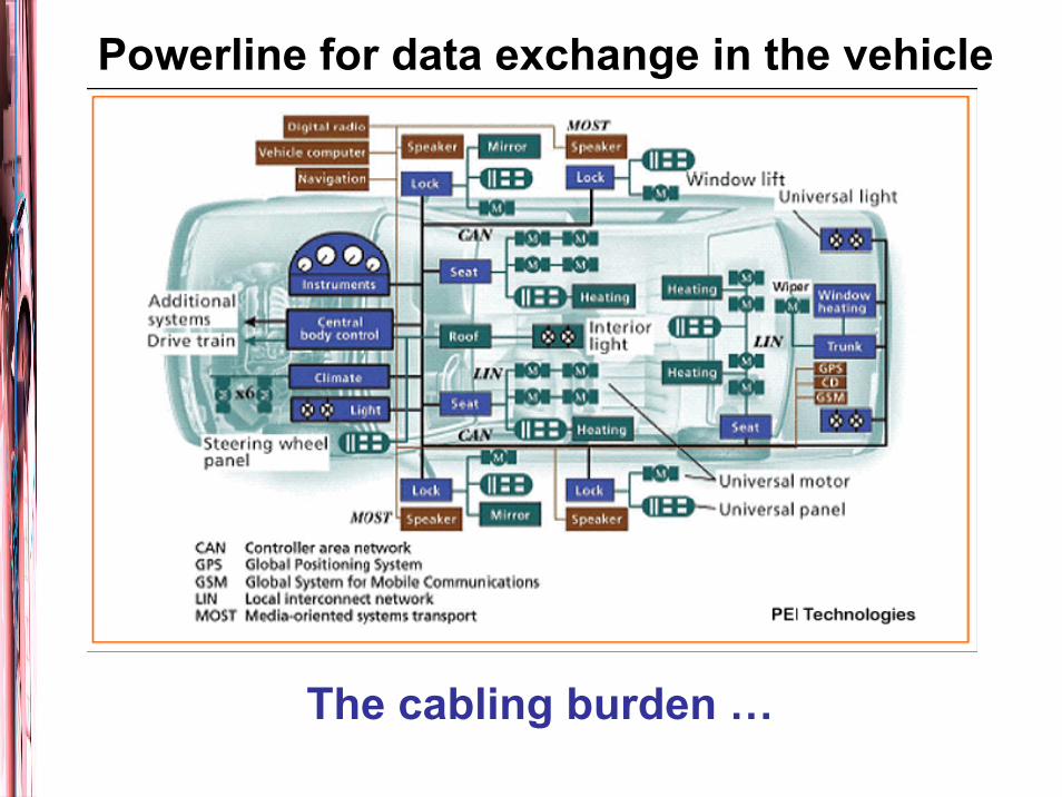
Powerline for data exchange in the vehicle
The cabling burden …
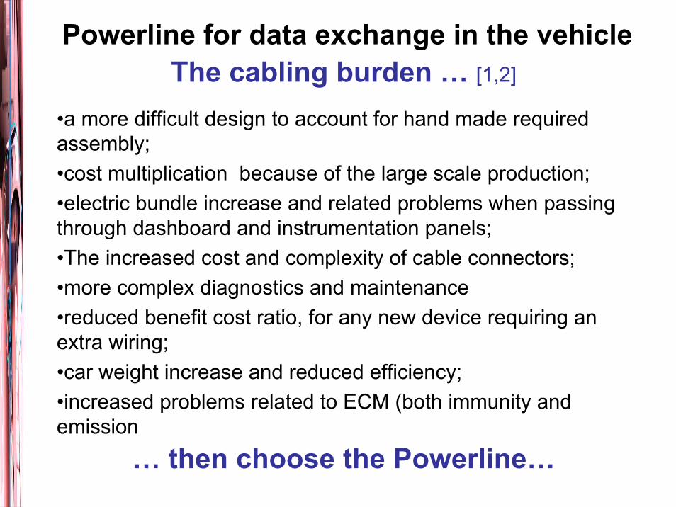
Powerline for data exchange in the vehicleThe cabling burden … [1,2]
•a more difficult design to account for hand made requiredassembly;•cost multiplication because of the large scale production;•electric bundle increase and related problems when passingthrough dashboard and instrumentation panels;•The increased cost and complexity of cable connectors;•more complex diagnostics and maintenance•reduced benefit cost ratio, for any new device requiring anextra wiring;•car weight increase and reduced efficiency;•increased problems related to ECM (both immunity and emission
… then choose the Powerline…
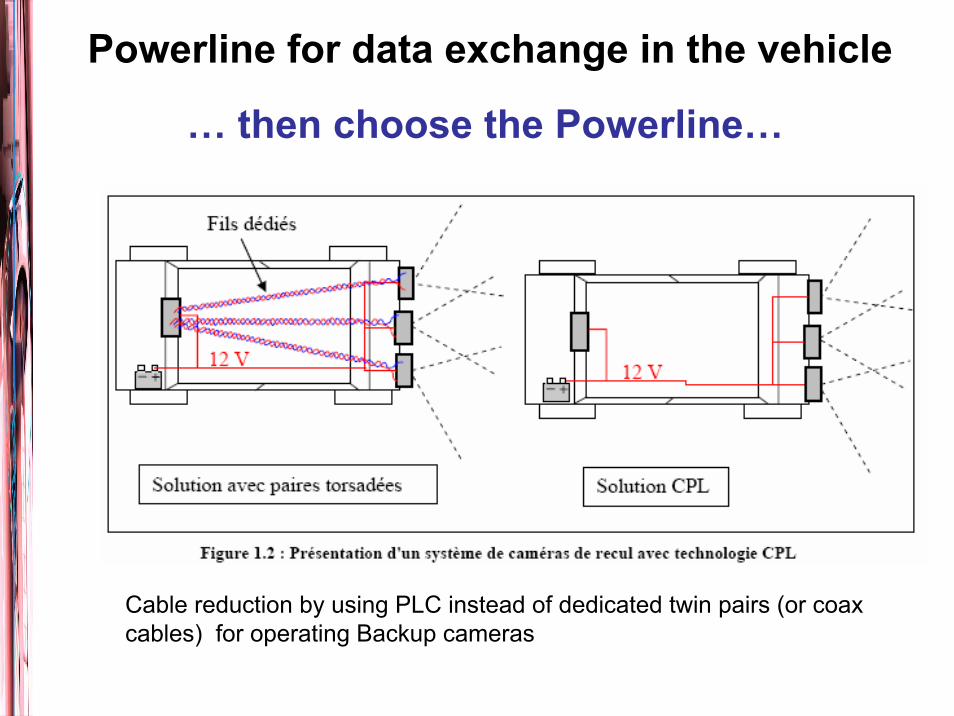
Powerline for data exchange in the vehicle
… then choose the Powerline…
Cable reduction by using PLC instead of dedicated twin pairs (or coaxcables) for operating Backup cameras

Powerline communication applicationsso far …
The idea of using the power cable to communicate arises because of POWER UTILITIES requirements to interconnect and controlfaraway units:
•communication over high and medium voltage AC cables
•reduced bitrate requirements (1,2 – 38,4 kbps / 4kHz Band, speech and SCADA networks)
When coming to low voltage, the powerline seems useful for domesticmeter reading, electric load management and HOME AUTOMATIONdiffusion, by also providing substantial cable reduction when comparedto wired dedicated transmission:
•communication over low voltage AC cables (110-240 V, 50-60 Hz)
•variable bitrate requirements (from on-off control to audio-video signals )

Powerline communication principles
The (digital) signal to be transmitted is modulated over the power line, by a proper coupler device, at an higher frequency in a givenrange; it is propagated over the power network; it can be decoupledand decoded in a different node of the network as long as a properdevice (node) is provided.
A coupling transformer withhigh pass characteristic forAC coupling
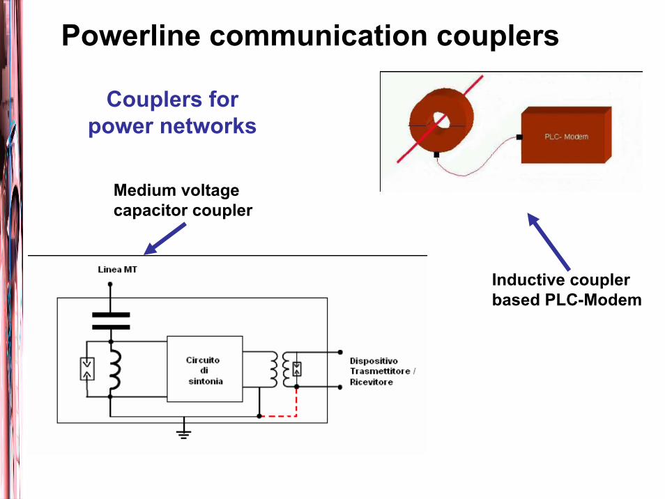
Powerline communication couplers
Medium voltagecapacitor coupler
Inductive couplerbased PLC-Modem
Couplers forpower networks
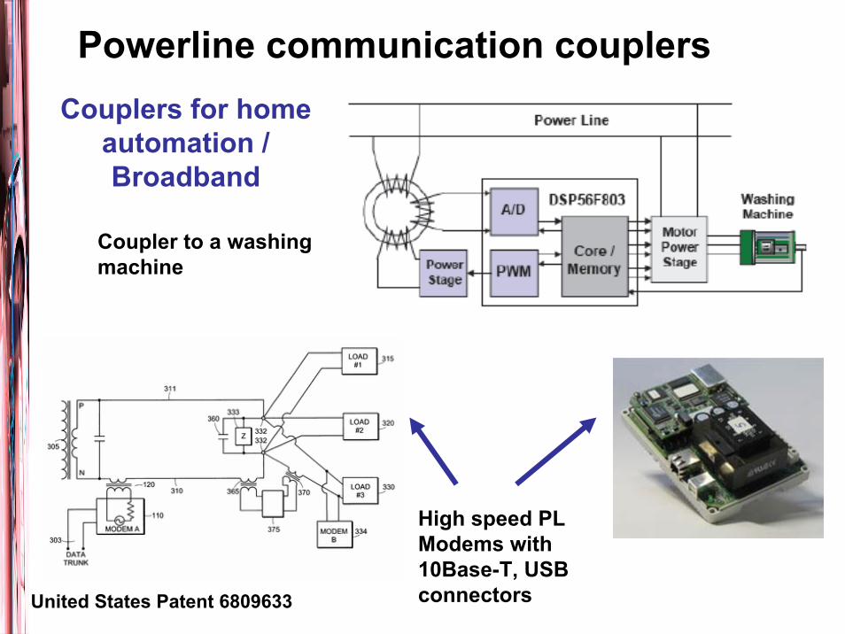
Powerline communication couplersCouplers for home
automation / Broadband
Coupler to a washingmachine
High speed PL Modems with10Base-T, USB connectorsUnited States Patent 6809633

Powerline communication couplersCouplers for DC powerline
For DC power line carriers, coupling can be accomplished simplyby using a series capacitor. An ideal capacitor would block the dc power voltage, and pass highfrequencies perfectly for a wide range of terminating impedancevalues.
The -3dB (half-power) cutoff point fLF would be
The suitability of a certain coupling capacitor depends onthe impedance of the load into which it terminates.
12LFf
RCπ=

148,5 kHz
Performance and regulationLow frequencies regulation. Max bitrate 1 Mbps
Europe - Standard CENELEC - EN 50065-1
A – Power utilities B – Home
automationD – Home automation. Alarmsand security
C – Home automationprotocols

1 5 10 15 20 25 30 MHz
CB – Radio amateur
ADSL VDSL
PLC
Cabled network return
1,6
Work in progress: CENELEC SC205A WG10up to 30 MHz
Performance and regulationHigher frequencies not yet regulated.
Bitrate up 10 Mbps and over
Performance and modulation techniques
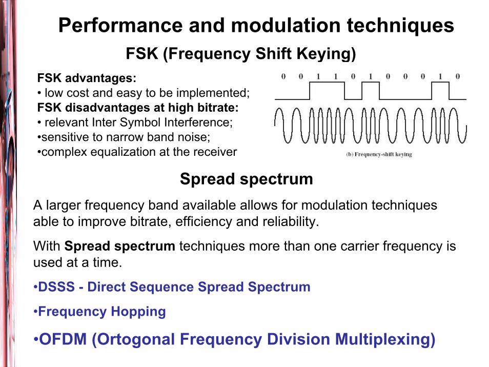
Spread spectrumA larger frequency band available allows for modulation techniquesable to improve bitrate, efficiency and reliability.
With Spread spectrum techniques more than one carrier frequency isused at a time.
•DSSS - Direct Sequence Spread Spectrum
•Frequency Hopping
•OFDM (Ortogonal Frequency Division Multiplexing)
FSK (Frequency Shift Keying)FSK advantages:• low cost and easy to be implemented; FSK disadvantages at high bitrate:• relevant Inter Symbol Interference;•sensitive to narrow band noise;•complex equalization at the receiver

Performance and modulation techniquesOFDM
OFDM Advantages:• high spectral efficiency and robust to narrow band interferences; • flexible and adaptive (each subcarrier can be independently modulated)• easy to synchronizeOFDM Disadvantages:• high peak power and emission•not yet standardized in the high frequencies range
N orthogonals sub-carriers are phase and amplitude modulated.The total required band is the sum of the sub-carrier frequencies.
It can also be implemented in the low frequency range (Project Prime -Iberdrola [
Differences and similarity between channel transfer function in domesticlines and car lines.
Multipath
Non/flat frequency spectrum with a number of notches, making it difficult to operate over large spectrum band (unless a spread spectrum technique is used)
Impulsive noise
Due to connected nonlinear devices and motor drives
Topology
In a house: 3-4 wires grouped in a cable merging in the distributionboard; transmitting mostly electric energy.
In a car: 3-50 wires confined in a limited space close to the chassis, working as a ground; transmitting electric energy and different protocolsignal among car units.
The channel characterization [2]

The channel characterizationBackground noise - Superposition of different, time variable (minutes, hours), noise sources, depending e.g. on the vehicle state, partiallydamped by the common metal body of the car. Coloured, not white noise, more relevant in low frequencies. Relatively low spectral density. Narrow band noise - Mostly related to the wiring captation of radio broadcasting. Sinusoidal, amplitude modulated signals, also depending on the geographical location.Impulsive noise - Produced by the numerous electric systems on board. Can be divided into:
single transient or pulse
burst characterized by a succession of elementary pulses

The channel characterization – Details: Marc Olivas Carrion, Thèse [2]Modélisation déterministe et de la fonction de transfert du canal
Caractérisation expérimentale du canal
Les résultats de l’analyse statistique ont montré queles paramètres de la modulation OFDM définis par la norme HomePlug 1.0 étaient bien adaptés auxcaractéri-stiques du canal de propagation sur le réseau électrique 12 V.
Le Bruit impulsif sur le réseauélectrique 12V des véhicules

Born to serve the demand for sending digital voice, video and Internet data within the home, based on Powerline transmission
HomePlug 1.0 was released in June 2001 by the HomePlug Alliance.
PLC Protocols – HomePlug 1.0
Physical layer. The OFDM used by HomePlug is specially tailored forpowerline environments. It uses 84 equally spaced subcarriers in the frequency band between 4.5MHz and 21MHz. To overcome impulsive noise uses forward error correction (FEC), error detection, data interleaving, and automatic repeat request (ARQ).
Medium Access Control is modeled to work with IEEE 802.3 frameformats. This choice simplifies the integration with Ethernet frames.
Frame format. Long format (up to 160 OFDM symbols). Short format.
Channel access mechanism. Is a variant of the CSMA/CA scheme (Carriersensing). In case of busy bus the new access is prioritized.
Segmentation and Reassembly mechanism. Quality of Service features.

PLC Protocols – HomePlug 1.0Performances
Physical Layer throughputs for various modulation and FEC choices
Comparison of HomePlug with other (home automation) technologies
Field Tests• 77% of the power line links will support at least 5Mbps of MAC throughput• 98% of the power line links will support at least 1.5Mbps MAC throughput.
HomePlug AV supports distribution data and multistream entertainment.HomePlug AV was released in 2005 by the HomePlug Alliance.
PLC Protocols – HomePlug AV
Physical layer. Operates in the frequency range of 2 - 28 MHz and provides a 200 Mbps physical channel rate and a 150 Mbps information rate.
Long OFDM symbols with 917 usable carriers (tones) are used.
Medium Access Control provides•a connection-oriented Contention Free (CF) service to support demanding AV
and IP applications, based on periodic Time Division Multiple Access (TDMA);
•a connectionless, prioritized service based on CSMA/CA technology, appliedto only traffic at the highest pending priority level.
Both features are accomodated by a Central Coordinator establishing a Beacon Period and a schedule. Distributors in EuropeDevolo AG – GermanyIntellon CorporationZyXEL

PLC Protocols – HomePlug AV
Example of Beacon Period Structure

PLC Protocols – HomePlug ComponentsDevolo® dLAN® 200 AVminiPCIIs an integrated device for transmitting and receiving data over the powerline. Together with the dLAN® Coupling Device it holds all functions necessary for enabling HomePlug®AV network functionality on devices with one free Mini PCI Slot.
Devolo® dLAN® Coupling Device
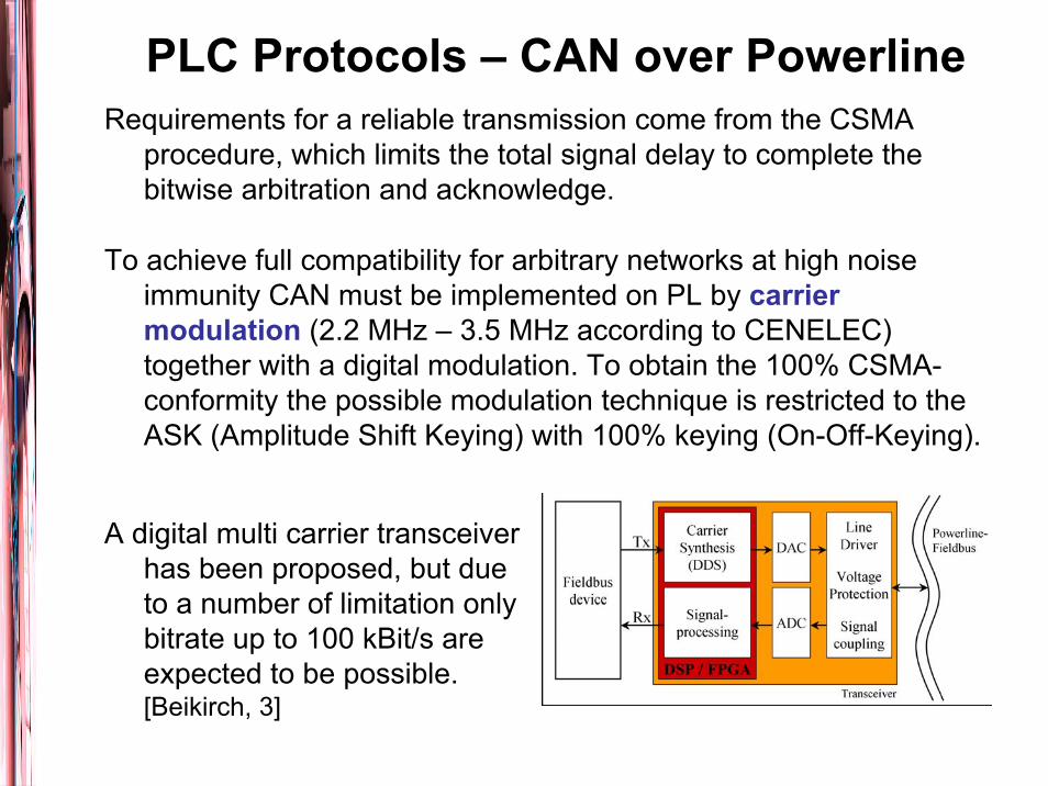
PLC Protocols – CAN over PowerlineRequirements for a reliable transmission come from the CSMA
procedure, which limits the total signal delay to complete the bitwise arbitration and acknowledge.
To achieve full compatibility for arbitrary networks at high noise immunity CAN must be implemented on PL by carrier modulation (2.2 MHz – 3.5 MHz according to CENELEC) together with a digital modulation. To obtain the 100% CSMA-conformity the possible modulation technique is restricted to the ASK (Amplitude Shift Keying) with 100% keying (On-Off-Keying).
A digital multi carrier transceiver has been proposed, but due to a number of limitation only bitrate up to 100 kBit/s are expected to be possible. [Beikirch, 3]
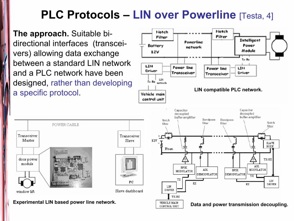
PLC Protocols – LIN over Powerline [Testa, 4]
The approach. Suitable bi-directional interfaces (transcei-vers) allowing data exchange between a standard LIN network and a PLC network have been designed, rather than developing a specific protocol.
Data and power transmission decoupling.Experimental LIN based power line network.
LIN compatible PLC network.

Powerline for automotive – What’s going onLow bitrate (up to 2 Mbps)
•YAMAR (Israel) well established company. Solutions basedon transmission overv battery cables and CAN protocol•Valeo (lower bitrate)•Research Theses en France (Spread Spectrum over 4 MHz, up to 2 Mbps and CAN) [Degardin, 5]
Higher bitrateExperimental setup for broadband automotive. Operatingbenchmarking results at 1 Mbps (4-FSK) and 5 Mbps (2-FSK) [Van Rensburg, 6]Research in Germany (BMW, Bosch) 1. To work with the actual (not ideal) cable distribution to gethigh bitrate perdformance2. To design a new cabling for the car to optimize even the transmission rate. [Dostert, 7]
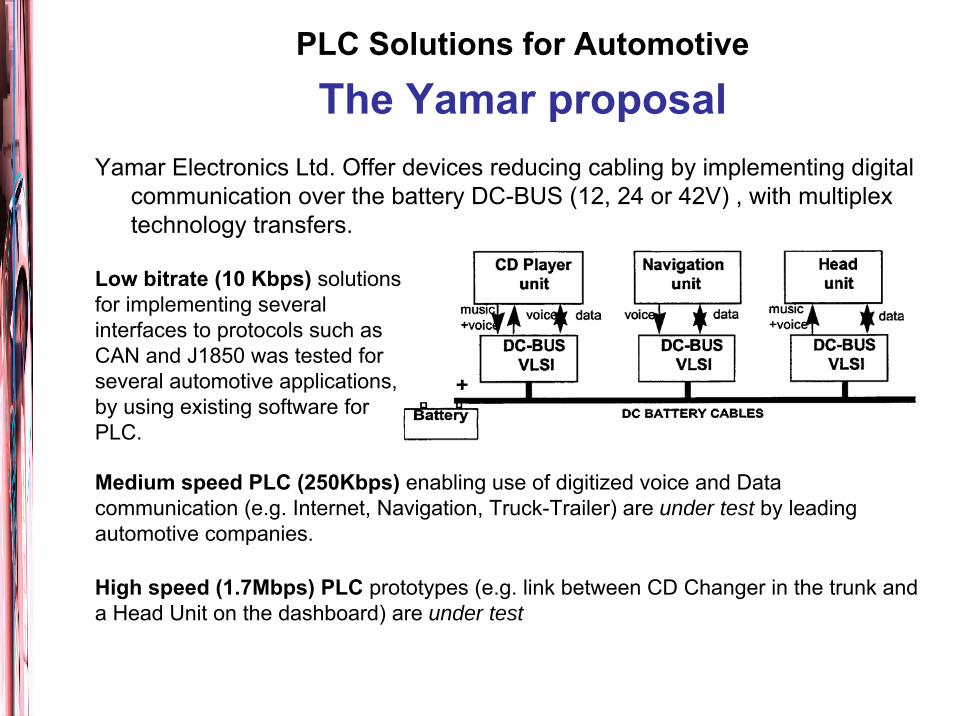
Yamar Electronics Ltd. Offer devices reducing cabling by implementing digitalcommunication over the battery DC-BUS (12, 24 or 42V) , with multiplextechnology transfers.
PLC Solutions for Automotive
The Yamar proposal
Low bitrate (10 Kbps) solutionsfor implementing severalinterfaces to protocols such asCAN and J1850 was tested forseveral automotive applications, by using existing software forPLC.
Medium speed PLC (250Kbps) enabling use of digitized voice and Datacommunication (e.g. Internet, Navigation, Truck-Trailer) are under test by leadingautomotive companies.
High speed (1.7Mbps) PLC prototypes (e.g. link between CD Changer in the trunk and a Head Unit on the dashboard) are under test
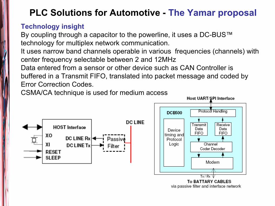
PLC Solutions for Automotive - The Yamar proposalTechnology insightBy coupling through a capacitor to the powerline, it uses a DC-BUS™technology for multiplex network communication.It uses narrow band channels operable in various frequencies (channels) withcenter frequency selectable between 2 and 12MHzData entered from a sensor or other device such as CAN Controller isbuffered in a Transmit FIFO, translated into packet message and coded byError Correction Codes.CSMA/CA technique is used for medium access

PLC Solutions for Automotive - The Yamar proposal
DCB500 – TransceiverCharacteristicsData transfer rate: 300 or 500 kbpsCollision resolution: Built in CSMA/CAError correction codes: Built in Forward Error Correction Code (ECC)Power save mode: Built in Sleepmoded.(Only 50 us to sense activity)Packet size: User definedInterface: UART or SPINetwork of up to 16 nodes.
PLC Solutions for Automotive - The Yamar proposal
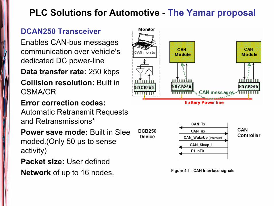
DCAN250 TransceiverEnables CAN-bus messagescommunication over vehicle's dedicated DC power-line Data transfer rate: 250 kbpsCollision resolution: Built in CSMA/CRError correction codes: Automatic Retransmit Requests and Retransmissions*Power save mode: Built in Sleepmoded.(Only 50 μs to senseactivity)Packet size: User definedNetwork of up to 16 nodes.
PLC Solutions for Automotive - The Yamar proposal
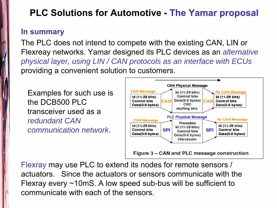
In summaryThe PLC does not intend to compete with the existing CAN, LIN orFlexreay networks. Yamar designed its PLC devices as an alternative physical layer, using LIN / CAN protocols as an interface with ECUsproviding a convenient solution to customers.
Flexray may use PLC to extend its nodes for remote sensors / actuators. Since the actuators or sensors communicate with theFlexray every ~10mS. A low speed sub-bus will be sufficient to communicate with each of the sensors.
Examples for such use is the DCB500 PLC transceiver used as a redundant CAN communication network.
Opportunity: is the PLC solution attractive for carmanufacturers?
Performances and technology: is the today technologyable to meet the performance requirements?
Research: what are the crucial issues tyhat deservesfurther insight and research work? Reliability, Real Time operation, EMC.
Lab experiments: how can be defined a viable lab experience?
PLC for automotive – Open issues
Experiments: Summary and goal
evaluate the issues related to PowerLine Communication (PLC) in the automotive domaindefine, implement and tune the experimental setupcarry out measurements on communication performance under realistic conditions (EMI, etc.) assess the timing behavior of the communication

Experimental setuphardware/software
FLEX Board from Evidence SRL (based on the Microchip dsPIC® DSC microcontrollerdsPIC33FJ256MC710)
DCB 500 Serial PLC Modem transceiver from Yamar LTD
Ignition System by Magneti Marelli
Erika Enterprise Real-time OS from Evidence SRL
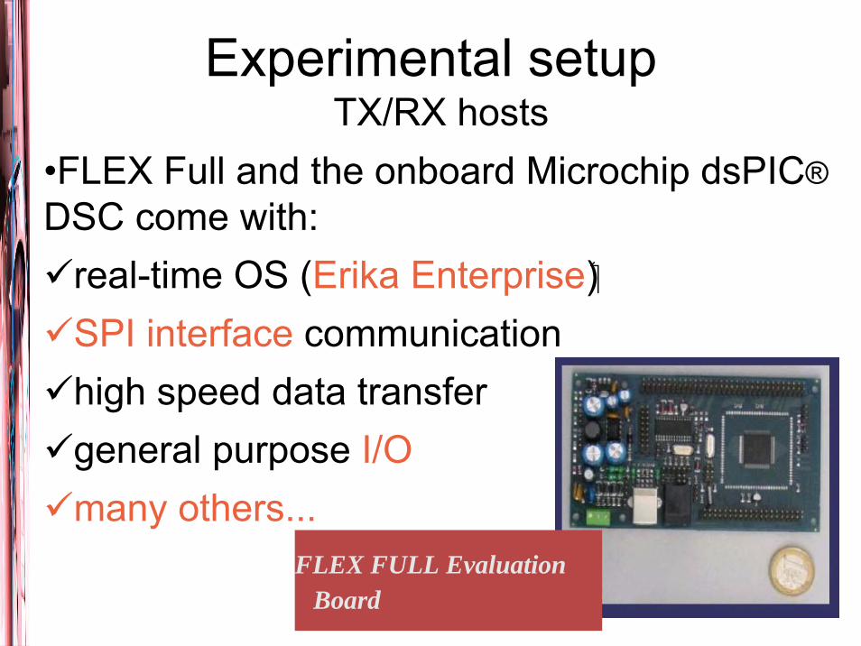
•FLEX Full and the onboard Microchip dsPIC®DSC come with:
real-time OS (Erika Enterprise)SPI interface communicationhigh speed data transfergeneral purpose I/Omany others...
Experimental setupTX/RX hosts
FLEX FULL Evaluation Board
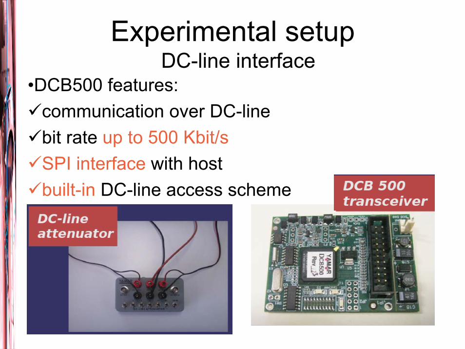
Experimental setupDC-line interface
•DCB500 features:communication over DC-linebit rate up to 500 Kbit/sSPI interface with hostbuilt-in DC-line access scheme
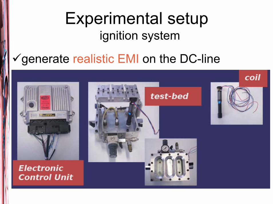
Experimental setupignition system
generate realistic EMI on the DC-line

Experiment roadmapstep 1
•DCB500 functioning test
check the correct operation of all devices
test the functionality using the supplied software package
send simple messages and test reception correctness (using UART at max speed of 115 Kbit/s)
ok
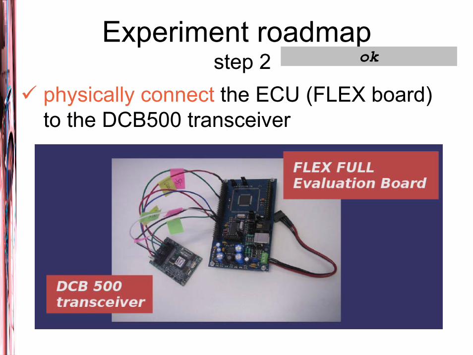
Experiment roadmapstep 2
physically connect the ECU (FLEX board) to the DCB500 transceiver
ok
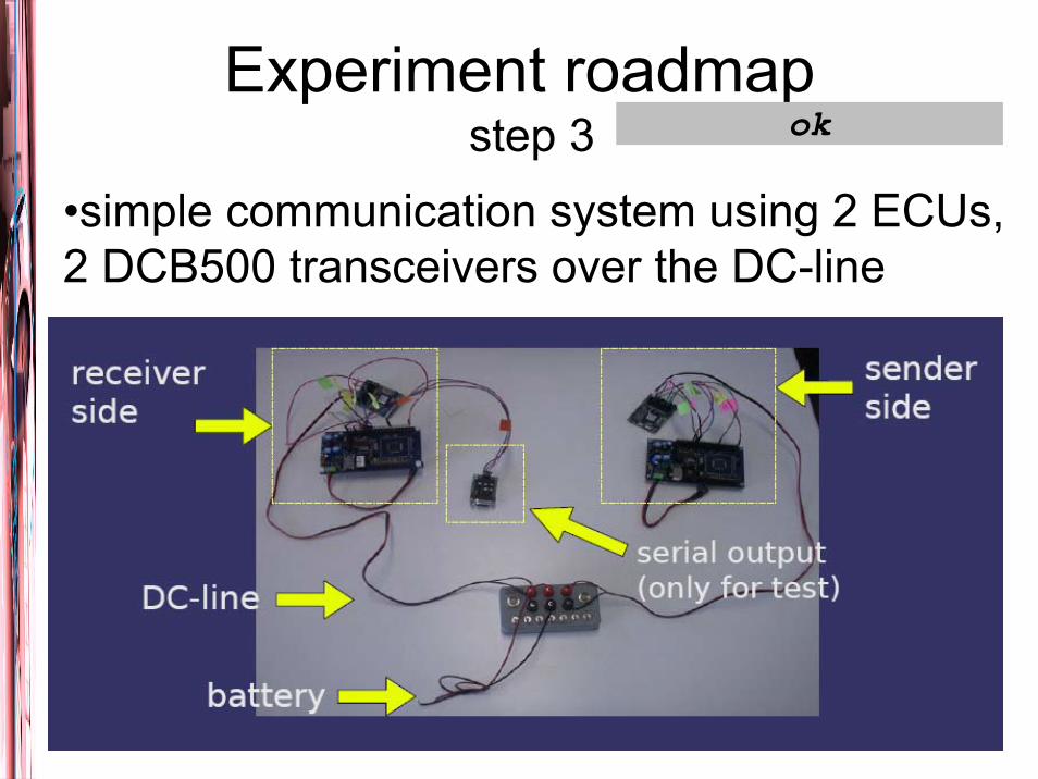
Experiment roadmapstep 3
•simple communication system using 2 ECUs, 2 DCB500 transceivers over the DC-line
ok
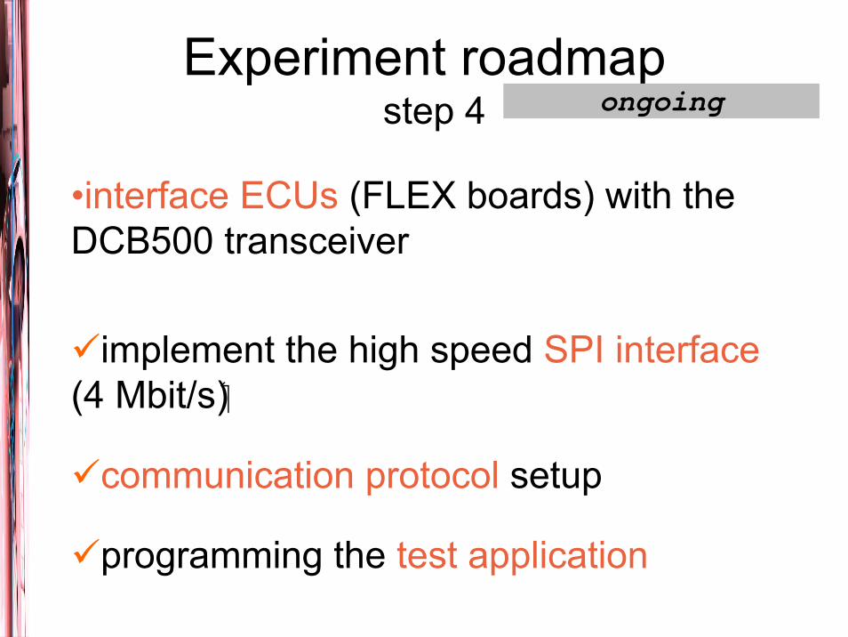
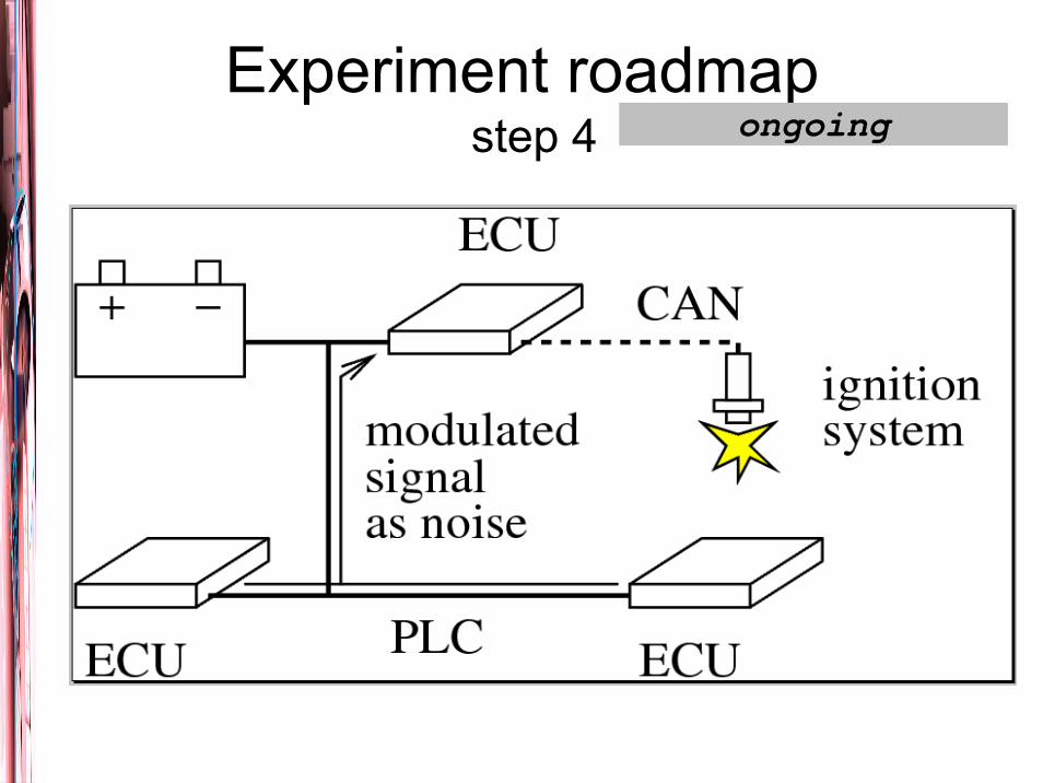
Experiment roadmapstep 4
•interface ECUs (FLEX boards) with the DCB500 transceiver
implement the high speed SPI interface(4 Mbit/s)
communication protocol setup
programming the test application
ongoing

Experiment roadmapstep 4 ongoing
Experiment roadmapstep 4 ongoing

Experiment roadmapstep 5
•using 2 ECUs, at the max possible speed without communication errors
throughput
response time
end to end latency
•introduce source of noise (i.e. ignition system, cell phones, etc.)
revaluation the communication performance
to be done
Conclusionssome preliminary work done
the main performance assessment to be done
what happens with many nodes connected?find people interested on the topicpossibility of collaboration on funded projects
future works and wishes
Robotics Lab. research activitiesreal-time operating sytems (scheduling, power-aware, multi-core, etc.)real-time wired/wireless communicationpower-line communication systemsembedded systems (Linux, etc.)autonomous robot navigation (mobile robots, manipulators, etc.)multi-robot co-ordinationdomotics
Electrical drives and automation labelectrical drives and machines controlelectrical drives, actuators and algorithms for industrial manipulatorsreal-time control in industrial environmentfieldbus protocols and application for industryfieldbus protocols and applications in domestic environment
[1] J. Axelsson, J. Fröberg, H.Hansson, C.Norström, K. Sandström, and B. Villing: Correlating bussines needs and network architectures in automotive Applications – a comparative case study - 5th IFAC International Conference on Fieldbus Systems and their Applications (FET), p 219-228, IFAC, Aveiro, Portugal[1a] PRIME Technology Whitepaper. PHY, MAC and Convergence layers, July 2008, available on: http://www.iberdrola.es/wcorp/corporativa/iberdrola?IDPAG=EN-SMART_METERING[2] Marc Olivas Carrion: Communications sur le réseau d’énergie électriqued’un véhicule : modélisation et analyse du canal de propagation – Thèse, Lille 2006.[3] Jan Taube, Helmut Beikirch, Matthias Voss: Real-Time Capabilities with Digital Powerline Communications Interfaces in CSMA/CA-Networks. Proceedings of RTN 2004, 3rd Int. Workshop on Real-Time Networks, Catania, Italy, June, 2004.[4] E. Arabia, C. Ciofi, A. Consoli, R. Merlino, and A. Testa: Electromechanical Actuators for Automotive Applications Exploiting Power Line Communication, SPEEDAM 2006 Proceedings[5] V. Degardin, M.Olivas Carrion, M. Lienard and P.: In-vehicle power line communication: Impulsive noise characteristics International Symposium on Power Line Communications, 2005 Vancouver, Canada[6] P. A. Janse van Rensburg, H. C. Ferreira and A. J. Snyders: An Experimental Setup for In-Circuit Optimization of Broadband Automotive Power-Line Communications. International Symposium on Power Line Communications, 2005 Vancouver, Canada [7] T. Huck, J. Schirmer, K. Dostert: Tutorial about the Implementation of a Vehicular High Speed Communication System. Power Line Communications and Its Applications, 2005 International Symposium[8] Yair Maryanka, Dr. Ofer Amrani, Amir Rubin: The Vehicle Power Line as a Redundant Channel for CAN Communication. SAE 2005 World Congress & Exhibition, April 2005, Detroit, MI, USA
REFERENCES