PLENA matrix Digital Sound System Surprisingly Flexible. Powerful ...

Powerful, Flexible, Easy to use – the CLV600 Series
A complete family of stationary bar code scanners for intelligent solutions in logistics and factory automation
P r o d u C t i n F o r m at i o n

2 S tat i o n a r y b a r C o d E S C a n n E r S – C LV 6 0 0 S E r i E S | S i C k 2 0 0 9 - 0 7
the complete family: CLV620, CLV630, CLV640, CLV650
Contents
The complete family: CLV620, CLV630, CLV640, CLV650 2
At home in many industries 4
Overview of the CLV600 series 6
Overview of CLV600 features 8
Product selection guide 9
Technical data 10
Dimensional drawings / reading field diagrams 12
Network integration 23
Connection Modules, Gateways, Proxy 24
Ordering information CLV600 series 26
Ordering information Connection Modules, Gateways, Proxy 28
Accessories 29
SOPAS-ET Single Device / SOPAS-ET configuration software 32
RDT400 Remote Diagnostic Tool 33
SICK Service for optimized Auto Ident solutions 34

3S i C k | S tat i o n a r y b a r C o d E S C a n n E r S – C LV 6 0 0 S E r i E S2 0 0 9 - 0 7
With the release of the new CLV650, the CLV600 family now covers nearly all industrial applications for automatic identification.
With a high scanning frequency of up to 1,200 Hz in combina-tion with Smart code reconstruction, the CLV600 series offers an excellent speed to reliability ratio.
We offer these powerful and easily installed products in two housing sizes, three designs, two connection types and two scanning technologies.
discover the compact bar code scanners of the CLV600 series: Powerful, Flexible, Easy to use.

4 S tat i o n a r y b a r C o d E S C a n n E r S – C LV 6 0 0 S E r i E S | S i C k 2 0 0 9 - 0 7
at home in many industries
The future demands greater reading performance, greater flexibility for product changes and optimum networkability – and at ever-decreasing sizes. In order to meet these de-mands we have developed the compact CLV600 series bar code scanners to easily solve automatic identification applications in nearly all industries. Leveraging our broad base of expertise across all markets, we can better understand your application in its entirety and offer you comprehensive solutions from a single source.
material handling and warehousing systems
• Complete CLV620–CLV650 product portfolio for nearly all reading requirements
• Excellent reading properties even with partially covered or damaged bar codes
• Flexible fieldbus connection• Quick disconnect connectors• External mirror hood reduces the reading distance
when used between two closely spaced conveyors• Rapid, easy replacement of bar code scanners due to
external parameter cloning
the automotive industry
• Long reading distances• Models with autofocus or dynamic focus available• Flexible fieldbus connection• Quick disconnect connectors• Silicon-free• Rapid, easy replacement of bar code scanners due to
external parameter cloning
Electronic industry
• High-density models for extremely small module widths• Excellent reading properties even with partially covered
or damaged bar codes, as well as low-contrast bar codes

5S i C k | S tat i o n a r y b a r C o d E S C a n n E r S – C LV 6 0 0 S E r i E S2 0 0 9 - 0 7
Pharmaceutical /clinical analyses
• Complete CLV620–CLV650 product portfolio for nearly all reading requirements
• Large depth of field for bar code identification over several racks
• Compact housing for mounting within test tube carousels
• Reliable and rapid decoding of codes on pharma-ceutical packages
document handling / letter sorting
• Extremely high triggering and decoding rate• Transport speeds of up to 6 m/s (1000 ft/min)
possible• Excellent reading properties, even with low-contrast
bar codes• Lightweight, compact housing
Food and beverage
• Excellent reading properties even on highly reflective material
• Transport speeds of up to 6 m/s (1000 ft/min) possible
• Available with plastic window upon request• IP 65 enclosure rating, also for the connection system
Stackers / industrial trucks
• Autofocus models available• Highly flexible data sorting and formatting• Highly flexible code comparison possibilities• Mounting brackets available with vibration and impact
dampening • Models with special cables on request

6 S tat i o n a r y b a r C o d E S C a n n E r S – C LV 6 0 0 S E r i E S | S i C k 2 0 0 9 - 0 7
overview of the CLV600 series
Powerful
• Very fast reading rate even with damaged, dirty and partially covered bar codes thanks to the significantly improved Smart code reconstruction algorithm
• Extremely high transport speeds of up to 6 m/s (1000 ft/min) possible
• Remote diagnostic ability via integrated web server or optional rdt400 remote diagnostic tool for visualizing long-term read statistics (see page 33)
Flexible
• Can, Ethernet tCP/iP and Ethernet iP on board − No additional Ethernet gateway required − Cost reduction for Ethernet connection − Safe investment: future industrial Ethernet protocols
can be fed-in via software update• Flexible fieldbus connection due to external fieldbus
gateways and fieldbus proxies (see page 23)• innovative data handling: data is transmitted to the
controller in desired form due to sorting, filter and out-put formatting
• Different focus versions (fixed focus, dynamic focus, autofocus) cover almost all reading distances
Easy to use
• Easy, intuitive user concept SoPaS-Et Single device or SoPaS-Et (see page 32)
• Connection Assistant for simple and rapid connection to bar code scanners. No extensive fieldbus knowledge necessary.
• Simple set-up even without PC through integrated buttons, LEd bar graph and intelligent auto Setup
• Simple and rapid replacement of a bar code scanner without re-configuration with a PC, due to parameter cloning via optional cloning module or optional micro-Sd card
• Simple mounting thanks to compact housing, flexible mounting technology – with rotating connectors and brackets for round bars
CLV630 / CLV640 / CLV650
CLV620
Simple connection assistant
the practical pivoting plug-in unit allows the CLV600 series family to be installed and connected even in difficult locations.result: more comfortable network construction, more rapid plug connection thanks to speedcon, and flexible mounting options.
reading of damaged codes thanks to Smart

7S i C k | S tat i o n a r y b a r C o d E S C a n n E r S – C LV 6 0 0 S E r i E S2 0 0 9 - 0 7
Housings
Front reading windowAvailable for the entire CLV600 series
Side reading window, light exit below 105° (not CLV65x)
Side reading window with oscillating mirror (not CLV62x)The oscillating mirror allows bar codes to be read within larger areas.
In addition to parking(adjustablefixedpositionofthescanning line) or continuous oscillation independent of the reading cycle, optimized functional processes – based on the reading cycle – are also possible in the oscillating mirror’s Controlled mode:
− n-fold oscillations around an adjustable starting position within the reading cycle
− one-shot: single swing (to and from) per reading cycle from an adjustable starting position
OscillatingMirror
Front reading window
Side reading window with oscillating mirror
types of connections
Standard version15-pin cable with D-Sub-HD plug Compatible with pin occupancy of the CLV400 series
Ethernet versionM12 socket for Ethernet interface;M12 plug for power supply, triggering, host & auxiliary interfaces and CAN bus;No additional Ethernet gateway required for operation.Protocols: Ethernet TCP/IP, Ethernet IP
Ethernet
Special models
Plastic windowSpecial models with plastic window are available upon request for the food industry. Simply ask your local SICK Sales Representative.
External mirror hoodReduces the reading distance when used between two closely spaced conveyors
Ethernet version
Standard version
Line scanner raster scanner Line scanner with oscillating mirror
External mirror hood
Side reading window

8 S tat i o n a r y b a r C o d E S C a n n E r S – C LV 6 0 0 S E r i E S | S i C k 2 0 0 9 - 0 7
overview of CLV600 features
device features
two function buttons“Select” + “Start/End” for functions such as:
− Start Auto Setup − Teach-in of a match code − Start reading diagnosis
LEd bar graphNo PC is necessary to check the reading performance
intelligent auto SetupAutomatically optimizes the bar code scanner for the codes that need to be read.
micro-Sd flash cardIntegrated Micro-SD card slot allows simple and rapid replacement of bar code scanners. This is carried out using external parameter cloning –noneedtoconfigureusingaPC,ensuring quick MTTR*).
LED Bar Graph
2 x Button
Micro SDCard
CAN
FocusFixedfocusforfixedvalues,dynamicfocus for reading at multiple read-ing distances, and automatic focal point switching in real time with in-tegrated distance measurement (no supplementary photoelectric sensors required)
Smart (code reconstruction) Damaged, dirty and/or partially cov-ered bar codes are also reliably read. There are two versions with differing tilt tolerances.
CanIntegrated CAN bus supports:
− CANopen®
− SICK CAN-sensor network for easy formation of scanner groups
− No additional multiplexer required
micro-Sd flash card integrated micro-Sd card slot
IntelligentAuto Setup
0% 100%
SMART620 SMART
Dyn. Focus DistanceMeasuring
2001000
Auto FocusFixed Focus
LEd bar graphindicator LEds Function buttons
*) mttr = mean time to repair

9S i C k | S tat i o n a r y b a r C o d E S C a n n E r S – C LV 6 0 0 S E r i E S2 0 0 9 - 0 7
Product selection guide
device feature CLV62x CLV63x CLV64x CLV65x
Oscillating mirror model – OscillatingMirror
OscillatingMirror
OscillatingMirror
Ethernet version Ethernet Ethernet Ethernet Ethernet
Function buttons, LED bar graph – 2 x Button
LED Bar Graph 2 x Button
LED Bar Graph 2 x Button
LED Bar Graph
Integrated slot for supplementary flash card
– Micro SDCard
Micro SDCard
Micro SDCard
Intelligent Auto Setup IntelligentAuto Setup
0% 100%
IntelligentAuto Setup
0% 100%
IntelligentAuto Setup
0% 100%
IntelligentAuto Setup
0% 100%
Integrated CAN bus CAN CAN CAN CAN
Focus, distance measurement Fixed Focus Fixed Focus Dyn. Focus Auto Focus
DistanceMeasuring
2001000
SMART620 and SMART (code reconstruction)
SMART620 SMART SMART SMART
Dimensional drawings and read field diagrams ● From Page 12 ● From Page 14 ● From Page 17 ● From Page 21
Technical data ● From Page 10
Order information ● From Page 26
Accessories ● From Page 29
resolution (module width, mm) 0.15 0.2 0.25 0.35 0.5 1
Device / reading distance, min. to max. (mm)
CLV621 Fixed Focus, Long Range 220 to 490 170 to 545 60 to 730
CLV620 Fixed Focus, Mid Range 150 to 210 110 to 250 80 to 285 60 to 365
CLV622 Fixed Focus, Short Range 92 to 137 85 to 150 60 to 180 53 to 200
CLV630 Fixed Focus, Long Range 220 to 500 170 to 580 60 to 735
CLV631 Fixed Focus, Mid Range 165 to 330 140 to 400 90 to 450
CLV632 Fixed Focus, Short Range 110 to 190 70 to 250 60 to 285
CLV640 Dynamic Focus, Standard 62 to 245 60 to 380 55 to 530 55 to 660 60 to 840
CLV642 Dynamic Focus, High Density 30 to 220 30 to 335 30 to 345
CLV650 Auto Focus, Standard 175 to 550 160 to 1000 150 to 1200 130 to 1600
CLV651 Auto Focus, High Density 150 to 930
Quick overview of resolution / reading distance (front reading window)

1 0 S tat i o n a r y b a r C o d E S C a n n E r S – C LV 6 0 0 S E r i E S | S i C k 2 0 0 9 - 0 7
technical data
C LV 6 2 x C LV 6 3 x C LV 6 3 x o S C i L L at i n g m i r r o r
Laser diode (wavelength) Redlight(λ=655nm)
MTTF of laser diode 20,000 h
Laser class of device1) Class 2
Usable aperture Max. 50°
Scanning /decoder frequency 400 to 1,200 Hz
Oscillation frequ. / length of period – – 0.5 to 6.25 Hz / 2,000 to 160 ms
Max. amplitude – – +20° to –20°
Resolution 0.15 to 1.0 mm (type-dependent)
Raster height2) 15 mm (8 lines)
Bar code print contrast (PCS) ≥60%
Ambient light immunity 2,000 lx (on bar code)
Numb. of bar codes per scan Standard decoder 1 to 20; SMART/SMART620 decoder 1 to 6
Numb. of bar codes per read. gate3) 1 to 50 (auto-discriminating)
Bar code types Code 39, Code 128, Code 93, Codabar, EAN, EAN 128, UPC, 2/5 Interleaved, Pharmacode
Bar code length4) Max. 50 symbols
Print ratio 2:1 to 3:1
Number of multiple readings 1 to 99
Acoustic indicators5) Beeper (Buzzer)
Read cycles Cycle sources for start: switching inputs “Sensor 1”6) and/or “Sensor 2”; Command; Autocycle; CANCycle sources for stop: read cycle source, “Sensor 1”, “Sensor 2”, Command, Timer, Good Read, Condition
Data interface, “Host” Serial: RS 232 or RS 422/485; Ethernet (Port 2112), data format (serial) and data output format adjustable
Data transfer rate 2.4 to 115.2 kBd
Protocol SICK Standard (SOPAS-ET Cola A)
Physical configurations Stand-alone
Data interface, “Aux” Serial: RS 232 (57.6 kBd; 8 data bits, no parity, 1 stop bit); Ethernet (Port 2111), fixed data output format
Data interface, “Ethernet” Only with Ethernet version: 10/100 MBit /s; TCP/IP, half/full duplex
Data interface, “CAN” 20 kBit /s to 1 MBit /s, SICK CAN-sensor network (Master, Slave, Mulitiplexer)
Digital switching inputs6) 2 (Standard), 1 (Ethernet); Each version with 2 additional external inputs via CMC600
Digital switching outputs 2 (Standard), 0 (Ethernet); Each version with 2 additional external outputs via CMC600
Electrical connection Standard version: cable (0.9 m) with 15-pin D-Sub HD plugEthernet version: rotating plug unit with 2 x M12 round plug-in connectors (12-pin plug, 4-pin socket)
Operating voltage7)8) 10 to 30 V DC 18 to 30 V DC
Power consumption Typ. 4.5 W at 10 to 30 V DC Typ. 5 W at 18 to 30 V DC Typ. 6 W at 18 to 30 V DC
Housing / housing colour Aluminum die-cast / light blue (acc. to RAL 5012)
Electrical safety Acc. to EN 60950-1
Protection class III acc. to EN 61140
Enclosure rating IP 65, acc. to EN 60529; A1
EMC testing Emission of interference: acc. to EN 61000-6-3, immunity to interference: acc. to EN 61000-6-2
Vibration / impact immunity Acc. to EN 60068-2-6/acc. to EN 60068-2-27
Weight Standard9) / Ethernet10) 225 g / 205 g 320 g / 250 g 450 g / 350 g
Ambient / storage temperature 0 to +40 °C / –20 to +70 °C
Max. relative air humidity 90%,non-condensing1) Acc. to IEC 60825-1 and EN 60825-1, see warning label on device for date of publication; 2) At 200 mm reading distance (frontal read field); 3) Read gate: time window for code evaluation generated internally via read cycle; 4) Max. 5,000 symbols from all bar codes per read gate, 500 symbols with Multiplexer function (CAN); 5) Can be deactivated, potential function for results status indication

1 1S i C k | S tat i o n a r y b a r C o d E S C a n n E r S – C LV 6 0 0 S E r i E S2 0 0 9 - 0 7
C LV 6 4 x C LV 6 4 x o S C i L L at i n g m i r r o r
C LV 6 5 x C LV 6 5 x o S C i L L at i n g m i r r o r
Redlight(λ=655nm)
20,000 h
Class 2
Max. 50° (CLV642: max. 25°) Max. 50°
400 to 1,200 Hz 600 ... 1.000 Hz
– 0.5 to 6.25 Hz / 2,000 to 160 ms – 0.5 to 6.25 Hz / 2,000 to 160 ms
– +20° to –20° – +20° to –20°
0.2 to 1.0 mm (type-dependent) 0.25 to 1.0 mm (type-dependent) 0.5 to 1.0 mm (type-dependent)
15 mm (8 lines)
≥60%
2,000 lx (on bar code)
Standard decoder 1 to 20; SMART/SMART620 decoder 1 to 6
1 to 50 (auto-discriminating)
Code 39, Code 128, Code 93, Codabar, EAN, EAN 128, UPC, 2/5 Interleaved, Pharmacode
Max. 50 symbols
2:1 to 3:1
1 to 99
Beeper (Buzzer)
Cycle sources for start: switching inputs “Sensor 1”6) and/or “Sensor 2”; Command; Autocycle; CANCycle sources for stop: read cycle source, “Sensor 1”, “Sensor 2”, Command, Timer, Good Read, Condition
Serial: RS 232 or RS 422/485; Ethernet (Port 2112), data format (serial) and data output format adjustable
2.4 to 115.2 kBd
SICK Standard (SOPAS-ET Cola A)
Stand-alone
Serial: RS 232 (57.6 kBd; 8 data bits, no parity, 1 stop bit); Ethernet (Port 2111), fixed data output format
Only with Ethernet version: 10/100 MBit /s; TCP/IP, half/full duplex
20 kBit /s to 1 MBit /s, SICK CAN-sensor network (Master, Slave, Mulitiplexer)
2 (Standard), 1 (Ethernet); Each version with 2 additional external inputs via CMC600
2 (Standard), 0 (Ethernet); Each version with 2 additional external outputs via CMC600
Standard version: cable (0.9 m) with 15-pin D-Sub HD plugEthernet version: rotating plug unit with 2 x M12 round plug-in connectors (12-pin plug, 4-pin socket)
18 to 30 V DC
Typ. 5 W at 18 to 30 V DC Typ. 6.5 W at 18 to 30 V DC Typ. 8.5 W at 18 to 30 V DC Typ. 9.5 W at 18 to 30 V DC
Aluminum die-cast / light blue (acc. to RAL 5012)
Acc. to EN 60950-1
III acc. to EN 61140
IP 65, acc. to EN 60529; A1
Emission of interference: acc. to EN 61000-6-3, immunity to interference: acc. to EN 61000-6-2
Acc. to EN 60068-2-6/acc. to EN 60068-2-27
320 g / 250 g 450 g / 350 g 406 g / 336 g
0 to +40 °C / –20 to +70 °C
90%,non-condensing6) Ethernet version: only switching input Sensor 1; 7) Acc. to IEC 60364-4-41 (SELV and PELV acc. to IEC 60364-4-41); 8) The CLV600 bar code scanners are cer-tificated according to UL60950-1 when a LPS or Class 2 power supply is used. Valid with corresponding product marking on the nameplate. The enclosure rating (IP) is not tested by UL; 9) With connection cable (frontal read window); 10) Without connection cables (frontal read window)

1 2 S tat i o n a r y b a r C o d E S C a n n E r S – C LV 6 0 0 S E r i E S | S i C k 2 0 0 9 - 0 7
Standard version
Ethernet version
Reading field height (mm)
Reading distance (mm)
0
-80-40
4080
120160200240280320
-120-160-200-240-280-320
0 300 400 500 600 700 800200100
0.35 mm0.5 mm1.0 mm
Resolution
CLV621 – Long range
dimensional drawings / reading field diagramsCLV62x, front reading window
Reading field height (mm)
Reading distance (mm)
Auflösung
0
-40-20
20406080
100120140160
-60-80
-100-120-140-160
0 150 200 250 300 350 40010050
0.2 mm0.35 mm0.5 mm1.0 mm
Resolution
CLV620 – mid range
Reading field height (mm)
-100
-80
-60
-40
-20
20
40
60
80
100
0
0 150 200 25010050Reading distance (mm)
0.2 mm0.35 mm0.5 mm
Resolution0.15 mm
CLV622 – Short range
Standard version Ethernet version

1 3S i C k | S tat i o n a r y b a r C o d E S C a n n E r S – C LV 6 0 0 S E r i E S2 0 0 9 - 0 7
Standard version
Ethernet version
Reading field height (mm)
Reading distance (mm)
Auflösung
0
-80-40
4080
120160200240280320
-120-160-200-240-280-320
0 300 400 500 600 700 800200100
0.35 mm0.5 mm1.0 mm
Resolution
CLV621 – Long range
Reading field height (mm)
Reading distance (mm)
Auflösung
0
-40-20
20406080
100120140160
-60-80
-100-120-140-160
0 150 200 250 300 350 40010050
0.2 mm0.35 mm0.5 mm1.0 mm
Resolution
CLV620 – mid range
Reading field height (mm)
-100
-80
-60
-40
-20
20
40
60
80
100
0
0 150 200 25010050
0.2 mm0.35 mm0.5 mm
Resolution0.15 mm
Reading distance (mm)
CLV622 – Short range
dimensional drawings / reading field diagramsCLV62x, side reading window
Standard version Ethernet version

1 4 S tat i o n a r y b a r C o d E S C a n n E r S – C LV 6 0 0 S E r i E S | S i C k 2 0 0 9 - 0 7
dimensional drawings / reading field diagramsCLV63x, front reading window
Standard version Ethernet version
Standard version
Ethernet version
0
‒100
100
200
300
400
‒200
‒300
‒4000 400 500 600 700 800200 300100
Reading distance (mm)
Reading field height (mm)
0.35 mm0.5 mm1.0 mm
Resolution
CLV630 – Long range
0
‒100
100
200
‒2000 400 500200 300100
Reading distance (mm)
Reading field height (mm)
0.25 mm0.35 mm0.5 mm
Resolution
CLV631 – mid range
0
‒50
50
150
100
‒100
‒1500 200 250 300100 15050
Reading distance (mm)
Reading field height (mm)
0.2 mm0.35 mm0.5 mm
Resolution
CLV632 – Short range

1 5S i C k | S tat i o n a r y b a r C o d E S C a n n E r S – C LV 6 0 0 S E r i E S2 0 0 9 - 0 7
dimensional drawings / reading field diagramsCLV63x, side reading window
Standard version Ethernet version
Standard version
Ethernet version
0
‒100
100
200
300
400
‒200
‒300
‒4000 400 500 600 700 800200 300100
Reading field height (mm)
Reading distance (mm)
0.35 mm0.5 mm1.0 mm
Resolution
CLV630 – Long range
0
‒100
100
200
‒2000 400 500200 300100
Reading distance (mm)
Reading field height (mm)
0.25 mm0.35 mm0.5 mm
Resolution
CLV631 – mid range
0
‒50
50
150
100
‒100
‒1500 200 250 300100 15050
Reading distance (mm)
Reading field height (mm)
0.2 mm0.35 mm0.5 mm
Resolution
CLV632 – Short range

1 6 S tat i o n a r y b a r C o d E S C a n n E r S – C LV 6 0 0 S E r i E S | S i C k 2 0 0 9 - 0 7
dimensional drawings / reading field diagramsCLV63x with oscillating mirror
Standard version Ethernet version
0
‒100
100
200
300
400
‒200
‒300
‒4000 400 500 600 700 800200 300100
Reading field height (mm)
Reading distance (mm)
0.35 mm0.5 mm1.0 mm
Resolution
CLV630 – Long range
0
‒100
100
200
‒2000 400 500200 300100
Reading distance (mm)
Reading field height (mm)
0.25 mm0.35 mm0.5 mm
Resolution
CLV631 – mid range
0
–50
50
150
100
‒100
‒1500 200 250 300100 15050
Reading distance (mm)
Reading field height (mm)
0.2 mm0.35 mm0.5 mm
Resolution
CLV632 – Short range
Standard version
Ethernet version

1 7S i C k | S tat i o n a r y b a r C o d E S C a n n E r S – C LV 6 0 0 S E r i E S2 0 0 9 - 0 7
dimensional drawings / reading field diagramsCLV640 , front reading window
Standard version Ethernet version
40036032028024020016012080Focus position (mm)
700
600
500
400
300
200
100
0
1,400
1,200
1,000
800
600
400
200
0
Reading distance (mm) Scanning frequency (Hz)
1,200 Hz1,100 Hz
900 Hz800 Hz
3
2
1
54
CLV640 – dynamic, resolution 0.50 mmStandard version
Ethernet version
CLV640 – dynamic, resolution 0.35 mm
40036032028024020016012080
600
500
400
300
200
100
0
1,200
1,000
800
600
400
200
0
1,200 Hz
800 Hz
750 Hz 700 Hz
354
2
1
Focus position (mm)
Reading distance (mm) Scanning frequency (Hz)
CLV640 – dynamic, resolution 0.25 mm
36032028024020016012080
400
350
300
250
200
150
100
50
0
1,200
1,050
900
750
600
450
300
150
0
1,200 Hz
600 Hz
700 Hz
54
Focus position (mm)
Reading distance (mm) Scanning frequency (Hz)
3
2
1
1=Max.readingdist.(apertureangle25°);2=Max.readingdist.(apertureangle 50°); 3=Min.readingdist.;4=DOFα=25°;5=DOFα=50°

1 8 S tat i o n a r y b a r C o d E S C a n n E r S – C LV 6 0 0 S E r i E S | S i C k 2 0 0 9 - 0 7
dimensional drawings / reading field diagramsCLV640, side reading window
Standard version Ethernet version
Standard version
Ethernet version
12080 160 200 240 280 320 360
900 Hz
400
700
600
500
400
300
200
100
0
1,400
1,200
1,000
800
600
400
200
0
1,200 Hz1,100 Hz
800 Hz
Focus position (mm)
Reading distance (mm) Scanning frequency (Hz)
54
3
2
1
CLV640 – dynamic, resolution 0.50 mm
CLV640 – dynamic, resolution 0.35 mm
600
500
400
300
80 120 160 200 240 280 320 360 400
200
100
0
1,200 Hz
800 Hz750 Hz
700 Hz
800
1,000
1,200
600
400
200
0
Focus position (mm)
Reading distance (mm) Scanning frequency (Hz)
54 3
2
1
CLV640 – dynamic, resolution 0.25 mm
36032028024020016012080
400
350
300
250
200
150
100
50
0
1,200
1,500
900
750
600
450
300
150
0
600 Hz700 Hz
1,200 Hz
Focus position (mm)
Reading distance (mm) Scanning frequency (Hz)
54 3
2
1
1=Max.readingdist.(apertureangle25°);2=Max.readingdist.(apertureangle 50°); 3=Min.readingdist.;4=DOFα=25°;5=DOFα=50°

1 9S i C k | S tat i o n a r y b a r C o d E S C a n n E r S – C LV 6 0 0 S E r i E S2 0 0 9 - 0 7
dimensional drawings / reading field diagramsCLV640 with oscillating mirror
Standard version Ethernet version
Standard version
Ethernet version
40036032028024020016012080
700
600
500
400
300
200
100
0
1,400
1,200
1,000
800
600
400
200
0
1,200 Hz1,100 Hz
900 Hz800 Hz
Focus position (mm)
Reading distance (mm) Scanning frequency (Hz)
54 3
2
1
CLV640 – dynamic, resolution 0.50 mm
CLV640 – dynamic, resolution 0.35 mm
4003603202802402001601200
600
500
400
300
200
100
0
1,200
1,000
800
600
400
200
0
1,200 Hz
700 Hz
750 Hz800 Hz
Focus position (mm)
Reading distance (mm) Scanning frequency (Hz)
543
2
1
CLV640 – dynamic, resolution 0.25 mm
36032028024020016012080
400
350
300
250
200
150
100
50
0
1,200
1,050
900
750
600
450
300
150
0
1,200 Hz
700 Hz
600 Hz
Focus position (mm)
Reading distance (mm) Scanning frequency (Hz)
54
3
2
1
1=Max.readingdist.(apertureangle25°);2=Max.readingdist.(apertureangle 50°); 3=Min.readingdist.;4=DOFα=25°;5=DOFα=50°

2 0 S tat i o n a r y b a r C o d E S C a n n E r S – C LV 6 0 0 S E r i E S | S i C k 2 0 0 9 - 0 7
dimensional drawings / reading field diagramsCLV642 , front reading window
Standard version Ethernet version
350
300
250
200
150
0 50 100 150 200 250 300 350 400
100
50
0
800
1,000
1,200
600
400
200
0
1,200 Hz
850 Hz
600 Hz
Focus position (mm)
Reading distance (mm) Scanning frequency (Hz)
3
1
CLV642 – dynamic, High Density, resolution 0.25 mmStandard version
Ethernet version
CLV642 – dynamic, High Density, resolution 0.20 mm
350
300
250
200
150
0 50 100 150 200 250 300 350 400
100
50
0
800
1.000
1.200
600
400
200
0
1.200 Hz
850 Hz
600 Hz
Focus position (mm)
Reading distance (mm) Scanning frequency (Hz)
3
1
CLV642 – dynamic, High Density, resolution 0.15 mm
250
200
150
100
0 50 100 150 200 250 300 350 400
50
0
800
1,000
1,200
600
400
200
0
1,200 Hz1,150 Hz
700 Hz
Focus position (mm)
Reading distance (mm) Scanning frequency (Hz)
3
1
1=Max.readingdist.(apertureangle25°);3=Min.readingdist.

2 1S i C k | S tat i o n a r y b a r C o d E S C a n n E r S – C LV 6 0 0 S E r i E S2 0 0 9 - 0 7
dimensional drawings / reading field diagramsCLV65x, front reading window
Standard version Ethernet version
0
0 600 800 1,000 1,200 1,400 1,600 1,800400200
Resolution
Reading field height (mm)
Reading distance (mm)
500
0.25 mm 0.35 mm0.5 mm
1.0 mm
400300200100
-100-200-300-400-500
CLV650 – auto Focus
700650600550500450400350300250200
1,000900800700600500400300200100
0
Focus position (mm)
Reading distance (mm) Scanning frequency (Hz)
54 3
2
1
CLV651 – auto Focus, Low density
Standard version
Ethernet version
1=Max.readingdist.(Tilt0°);2=Max.readingdist.(Tilt45°);3=Min.readingdist.;4=DOFatTilt0°;5=DOFatTilt45°
Aperture angle 25°

2 2 S tat i o n a r y b a r C o d E S C a n n E r S – C LV 6 0 0 S E r i E S | S i C k 2 0 0 9 - 0 7
dimensional drawings / reading field diagramsCLV65x with oscillating mirror
Standard version Ethernet version
Standard version
Ethernet version
500400300200100
0
-200-100
-300-400-500
0 600 800 1,000 1,200 1,400 1,600 1,800400200
0.25 mm 0.35 mm0.5 mm
1.0 mm
Reading field height (mm)
Reading distance (mm)
Resolution
CLV650 – auto Focus
700650600550500450400350300250200
1,000900800700600500400300200100
0
Focus position (mm)
Reading distance (mm) Scanning frequency (Hz)
543
2
1
CLV651 – auto Focus, Low density
1=Max.readingdist.(Tilt0°);2=Max.readingdist.(Tilt45°);3=Min.readingdist.;4=DOFatTilt0°;5=DOFatTilt45°
Aperture angle 25°

2 3S i C k | S tat i o n a r y b a r C o d E S C a n n E r S – C LV 6 0 0 S E r i E S2 0 0 9 - 0 7
network integration
The CLV600 series can be integrated in numerous fieldbus applications without major wiring effort. The devices already have Ethernet and CAN interfaces. All devices can also be used as multiplexers in SICK CAN-sensor networks. The scanners can be integrated in PROFIBUS and DeviceNet networks via external fieldbus gateways. The “2-component” solution – device with separate connection module – offers the advantage that the scanner can be “buried” within the machine/system while the connection module remains easily accessible from outside.
Ethernet tCP/iP, Ethernet iP
ProFibuS devicenet
*) ProFibuS also possible via CmF400 with Cdm420
+Cdb620
e. g. CLV640 e. g. CLV62x
Canopen®/SiCk Can-sensor network/
rS 232/rS 422/rS 485
CdF600 *)
Ethernet Switch
e. g. IT3800g
SPS/Host
e. g. CLV62x
Cdm420 CmF400
e. g. CLV62x
e. g. CLV63x
ProFibuS

2 4 S tat i o n a r y b a r C o d E S C a n n E r S – C LV 6 0 0 S E r i E S | S i C k 2 0 0 9 - 0 7
Connection modules, gateways, Proxy
• Compact connection module for all SICK bar code scanners
• Integrated wiring diagram• Straightforward spring-loaded
contacts• IP 65 enclosure rating• Tension-relieved cables
+ Smaller footprint saves space + Easy wiring of all digital I/Os + Low investment requirement + Easy troubleshooting + Easy scanner replacement
through use of CMC600
Cdb620 basic Connection module
• Connection module for integration of: − Fieldbus modules − Network devices for power
supply − Display module
• Integrated connection diagram• Straightforward spring-loaded/
screw contacts• IP 65 enclosure rating• Tension-relieved cables
+ Easy to perform network integration
+ Parameter cloning for rapid scanner replacement
+ Monitoring/diagnosis via display + Simple mounting + Easy troubleshooting + AC power option with CMP4xx
power supply module
Cdm420 modular Connection module
• Rapid and simple mounting in CDB/CDM connection modules
• Plug&play functionality• Address monitoring through visible
rotary switch • Simplified commissioning of CAN
networks
+ Allows for quick rapid scanner re-placement if repair required
+ Rapid installation in existing con-nection devices
+ Easy to retrofit + No additional space requirement + No additional wiring effort
CmC600 External Parameter memory for Cdb620 and Cdm420
• Large illuminated display with 4 x 20 symbols
• 5 buttons for menu guidance • IP 65 enclosure rating
+ Good LCD visibility + Simple diagnosis of scanner + No PC connection required + Easy to retrofit + No additional wiring effort + Simple commissioning
Cmd400 External display module for Cdm420

2 5S i C k | S tat i o n a r y b a r C o d E S C a n n E r S – C LV 6 0 0 S E r i E S2 0 0 9 - 0 7
C m F 4 0 0 - 1 x 0 1 C d F 6 0 0 C m F 4 0 0 - 2 1 0 1Versions Gateway Proxy GatewayInterface
Data transfer rate, fieldbus 9.6 kBit/s to 12 MBit/s 125, 250, 500 kBit/s Data interface to bar code scanner
RS 232; 9.6 to 57.6 kBd RS 232; 57.6 kBd RS 232; 9.6 to 57.6 kBd
Electrical connection Gateway 26-pin SMD plug connector 6 x M12 (plug/socket);1 x 15-pin D-Sub HD socket
26-pin SMD plug connector
Electrical connection fieldbus 9-pol. D-Sub socket or 5-pin M12 plug/socket
5-pin M12 plug/socket 5-pin M12 plug
Power supply 18 to 30 V DC via CDM420 12VDCor24VDC±20% 18 to 30 V DC via CDM420Power consumption 2 W 5.0 W 2 W Enclosure rating IP 20/IP 65 IP 65
Temperature (operating/storage) 0 to +40 °C/–20 to +70 °CMax. rel. air humidity 90%,non-condensing• Ordering information see page 28 ff
C d b 6 2 0 C d m 4 2 0 / 4 9 0 / C d m 4 2 0 C m C 6 0 0Versions Basic Connection Module Modular Connection Module External Display Module for inte-
gration in CDB620 and CDM420Optical indicators 9 x LED 5/10 x LED 1 x LEDScanner connection 15-pin D-Sub HD socket –Service plug 9-pin D-Sub HD plug –Supply voltage Vscanner +1 V, (acc. to IEC 60364-4-41) 10 to 30 V DC via CDB/CDMPower consumption Pscanner +0.5 W 500 mWHousing PolycarbonateColour Light blue (acc. to RAL 5012) –Inspections CE CE, ULProtection Class Class 3 (acc. to EN 61140) Class 3 (acc. to EN 61140), with
power supply module: Class 1Class 3 (acc. to EN 61140)
Enclosure rating IP 65 (acc. to EN 60529; A1), on use of a SICK scanner standard connection cable
–
Dimensions (mm) 124.2 x 113.1 x 53.9 192 x 167 x 70 70 x 23 x 17Weight Approx. 260 g Approx. 800 g 30 gTemperature (operating/storage) 0 to +40 °C/–20 to +70 °CRelative air humidity Max.90%,non-condensing –• Ordering information see page 28 ff

2 6 S tat i o n a r y b a r C o d E S C a n n E r S – C LV 6 0 0 S E r i E S | S i C k 2 0 0 9 - 0 7
ordering information CLV600 series
type read range Scanning process
read window Standard version with 15-pin d-Sub Hd plug
Ethernet version with 2 x m12 plug connectors
type Order no. type Order no.
CLV621 Long range Line Front CLV621-0000 1041784 CLV621-0120 1041785
Raster Front CLV621-1000 1041786 CLV621-1120 1041787
Line Side CLV621-2000 1041788 CLV621-2120 1041789
Raster Side CLV621-3000 1041790 CLV621-3120 1041791
CLV620 mid range Line Front CLV620-0000 1040288 CLV620-0120 1041547
Raster Front CLV620-1000 1041548 CLV620-1120 1041549
Line Side CLV620-2000 1041550 CLV620-2120 1041551
Raster Side CLV620-3000 1041552 CLV620-3120 1041553
CLV622 Short range Line Front CLV622-0000 1041792 CLV622-0120 1041793
Raster Front CLV622-1000 1041794 CLV622-1120 1041795
Line Side CLV622-2000 1041796 CLV622-2120 1041797
Raster Side CLV622-3000 1041798 CLV622-3120 1041799
CLV62x
CLV63x
type read range Scanning process
read window Standard version with 15-pin d-Sub Hd plug
Ethernet version with 2 x m12 plug connectors
type Order no. type Order no.
CLV630 Long range Line Front CLV630-0000 1040706 CLV630-0120 1041969
Raster Front CLV630-1000 1041970 CLV630-1120 1041971
Line Side CLV630-2000 1041972 CLV630-2120 1041973
Raster Side CLV630-3000 1041974 CLV630-3120 1041975
Line scanner with oscillating mirror
Side CLV630-6000 1041976 CLV630-6120 1041977
CLV631 mid range Line Front CLV631-0000 1041978 CLV631-0120 1041979
Raster Front CLV631-1000 1041980 CLV631-1120 1041981
Line Side CLV631-2000 1041982 CLV631-2120 1041983
Raster Side CLV631-3000 1041984 CLV631-3120 1041985
Line scanner with oscillating mirror
Side CLV631-6000 1041986 CLV631-6120 1041987
2 7S i C k | S tat i o n a r y b a r C o d E S C a n n E r S – C LV 6 0 0 S E r i E S2 0 0 9 - 0 7
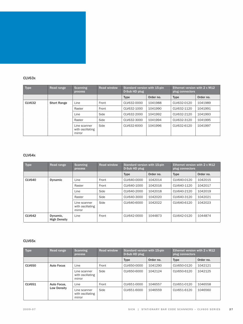
CLV63x
type read range Scanning process
read window Standard version with 15-pin d-Sub Hd plug
Ethernet version with 2 x m12 plug connectors
type Order no. type Order no.
CLV632 Short range Line Front CLV632-0000 1041988 CLV632-0120 1041989
Raster Front CLV632-1000 1041990 CLV632-1120 1041991
Line Side CLV632-2000 1041992 CLV632-2120 1041993
Raster Side CLV632-3000 1041994 CLV632-3120 1041995
Line scanner with oscillating mirror
Side CLV632-6000 1041996 CLV632-6120 1041997
CLV64x
type read range Scanning process
read window Standard version with 15-pin d-Sub Hd plug
Ethernet version with 2 x m12 plug connectors
type Order no. type Order no.
CLV640 dynamic Line Front CLV640-0000 1042014 CLV640-0120 1042015
Raster Front CLV640-1000 1042016 CLV640-1120 1042017
Line Side CLV640-2000 1042018 CLV640-2120 1042019
Raster Side CLV640-3000 1042020 CLV640-3120 1042021
Line scanner with oscillating mirror
Side CLV640-6000 1042022 CLV640-6120 1042023
CLV642 dynamic, High density
Line Front CLV642-0000 1044873 CLV642-0120 1044874
CLV65x
type read range Scanning process
read window Standard version with 15-pin d-Sub Hd plug
Ethernet version with 2 x m12 plug connectors
type Order no. type Order no.
CLV650 auto Focus Line Front CLV650-0000 1041290 CLV650-0120 1042121
Line scanner with oscillating mirror
Side CLV650-6000 1042124 CLV650-6120 1042125
CLV651 auto Focus, Low density
Line Front CLV651-0000 1046557 CLV651-0120 1046558
Line scanner with oscillating mirror
Side CLV651-6000 1046559 CLV651-6120 1046560

2 8 S tat i o n a r y b a r C o d E S C a n n E r S – C LV 6 0 0 S E r i E S | S i C k 2 0 0 9 - 0 7
ordering information Connection modules, gateways, Proxy
Order no. type description
Cdb620, basic connection module
1042256 CDB620-001 4 x M16 cable gland
1042257 CDB620-101 2 x M16 cable gland, 2 x M12 for simple CAN network wiring
1042258 CDB620-201 4 x M16 cable gland, 1 x M12 cable gland
Cdm420, modular connection module
1025362 CDM420-0001 6 x M16 cable gland
1028487 CDM420-0004 Connection of 2 x CLV6xx simultaneously via CAN network possible, 6 x M16 cable gland
CmC600, external parameter memory for CLV6xx for integration in Cdb620 / Cdm420
1042259 CMC600-101
Cmx modules, retrofit-enabled for Cdm420
2029466 CMD400 Display module
2029468 CMP400 Power supply unit, 11 W
2030091 CMP490 Power supply unit, 25 W, installation by replacement of lid of CDM420
Connection modules and accessories
Order no. type description
CmF400-1x01, ProFibuS-dP gateways
1026241 CMF400-1001 IP 20, 9-pin D-Sub socket
1026643 CMF400-1101 IP 65, 9-pin D-Sub socket
1028663 CMF400-1201 IP 65, 5-pin M12 plug/socket
CdF600, ProFibuS-dP Proxy
1041251 CDF600-0100 IP 65, M12 plug/socket
1041252 CDF600-0110 IP 65, M12 plug/socket, 12 V version for integration of a handheld scanner in the PROFIBUS network
CmF400-2101, devicenet gateway
1026242 CMF400-2101 M12 socket
gateways and Proxy

2 9S i C k | S tat i o n a r y b a r C o d E S C a n n E r S – C LV 6 0 0 S E r i E S2 0 0 9 - 0 7
accessories
Cables and connectors
Order no. Length description
CLV6
xxSt
anda
rd
CLV6
xxEt
hern
et
Cdb6
20
Cdm
420
CmF4
00
CdF6
00
6034414 2 m Cable, M12 4-pin, Ethernet to Host RJ45, plug/plug
●
6029630 3 m ●
6034415 5 m ●
6030928 10 m ●
6036158 20 m ●
6034420 2 m Cable, M12 4-pin, Ethernet to Host M12, plug/plug
●
6034421 3 m ●
6034422 5 m ●
2042916 0.9 m Cable, M12 12-pin, to CDB620/CDM400, CDF600 15-pin D-Sub HD, socket/plug
● ● ● ●
2041834 2 m ● ● ● ●
2042914 3 m ● ● ● ●
2042915 5 m ● ● ● ●
6034605 5 m Cable, M12 12-pin, to open cable end, socket
●
2014054 3 m Data connection cable (RS 232) for CLV6xxto PC, 2 x 9-pin D-Sub, socket/socket
● ●
6035396 Converter USB to RS 232, if RS 232 interface not available on PC ● ● ●
6034419 up to 3 m
Extension cable, 16 x 0.14 mm2 (AWG26), screened, by meter ● ●
6034417 2 m Extension cable, 15-wire, screened, with 15-pin D-Sub HD, plug/socket ● ●
6034418 3 m● ●
2043413 2 m Extension cable, 15-wire, screened, with 15-pin D-Sub HD, socket/open cable end, AWG26
● ●
4038847 IP 65 rubber seal for extension cables with 15-pin D-Sub HD plug-in connectors ● ●
6010019 D-Sub plug-in connector insert, 15-pin HD receptacle strip (socket), manual solder connection
● ●

3 0 S tat i o n a r y b a r C o d E S C a n n E r S – C LV 6 0 0 S E r i E S | S i C k 2 0 0 9 - 0 7
Order no. Length description
CLV6
xxSt
anda
rd
CLV6
xxEt
hern
et
Cdb6
20
Cdm
420
CmF4
00
CdF6
00
6010020 D-Sub plug-in connector insert, 15-pin HD plug strip (plug), manual solder connection ● ●
6009438 D-Sub plug-in connector housing (metal) for 9-pin D-Sub/15-pin D-Sub HD inserts
● ●
6027048 Unitron CAN cable 2 x 2 x 0.5 mm2, by meter ● ●
6021164 1 m CAN cable, M12, plug/socket ●
6021165 3 m ●
6021168 5 m ●
6021166 5 m CAN cable, M12 cable, socket/open cable end ●
6021167 CAN plug, M12, 5-pin, with resistor ●
6021195 2 m Parameterization cable for PC connection (9-pin Sub-D) to CDF600 (4-pin M8)
●
2027649 10 m ●
6025906 2 m Power supply, CDF600 M12, 5-pin plug (straight)/open cable end
●
6025908 10 m ●
6025909 2 m Power supply, CDF600 M12, 5-pin plug (angled)/open cable end
●
6025911 10 m ●
6021156 M12 plug, resistance, PROFIBUS ● ●
6021353 Bus IN, PROFIBUS cable socket, M12, 5-pin ● ●
6021354 Bus OUT, PROFIBUS cable plug, M12, 5-pin ● ●
6021355 PROFIBUS cable, 2 x 0.34 mm, by the meter ● ●
6025931 2 m Cable for digital I/Os for CDF600 M12, 5-pin, socket/plug ●
Cables and connectors
accessories

3 1S i C k | S tat i o n a r y b a r C o d E S C a n n E r S – C LV 6 0 0 S E r i E S2 0 0 9 - 0 7
brackets
Order no. description
CLV6
2x
CLV6
3x
CLV6
4x
CLV6
5x
2020410 Mounting bracket (simple angle)
● ● ● ●
2025526 Quick-action clamp
● ● ● ●
2042802 Round bar mounting (bracket) for round bars and pipes with an external diameter of 12 to 20 mm
●
2042902 Bracket with adapter plate
●
2042800 Mounting bracket, stirrup, incl. mounting material● ● ●
2042801 Round bar mounting (stirrup) for round bars and pipes with an external diameter of 12 to 20 mm, incl. mounting material
● ● ●
2042799 Mounting bracket with integrated vibration / shock absorber for mounting the scanner e.g. on a forklift
● ● ●
additional accessories
Order no. description
CLV6
2x
CLV6
3x
CLV6
4x
CLV6
5x
2046811 External mirror hood ● ● ● ●
2048633 Round bar mounting (bracket) for mounting the mirror hood on round bars and pipes with an external diameter of 12 to 20 mm ● ● ● ●
2046822 Hinge bracket for mounting the mirror hood on planar surfaces and ITEM profiles ● ● ● ●
4051366 Micro-SD Flash Card, memory medium with 512 MB ● ● ●
3 2 S tat i o n a r y b a r C o d E S C a n n E r S – C LV 6 0 0 S E r i E S | S i C k 2 0 0 9 - 0 7
SoPaS-Et Single device / SoPaS-Et configuration software
Those who use automation solutions from SICK benefit from a comprehensive network of solutions. The communication functions are combined in central software and thus offer high transparency and availability: SOPAS-ET Single Device and SOPAS-ET.
Thisconfigurationsoftwarewasdevelopedasacross-de-vice engineering tool for all SICK devices. With SOPAS-ET you can combine and centrally control individual compo-nents in a single project. Thanks to real time control, you can always keep an eye on all functions, and changes are immediately displayed. Using one software package leadstooptimumplantefficiencybecauseyoucanim-mediately react thanks to rapid and simple diagnosis. Detailed Online Help provides you with support.
This software provides many advantages when com-bined with CLV600 series bar code scanners. The scanner’sreadingfielddiagramscanbeloadedanddisplayed in SOPAS-ET. An event monitor allows rapid analysis of the scanner’s inputs and outputs. The effects of parameter changes are immediately visible via a diag-nostic monitor. An assistant allows rapid connection to thebarcodescanner.Nodetailedfieldbusknowledgeisnecessary.
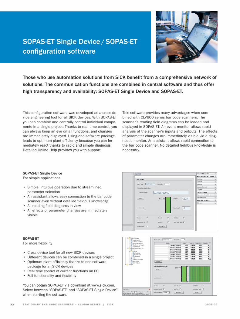
SoPaS-Et Single deviceFor simple applications
• Simple, intuitive operation due to streamlined parameter selection
• An assistant allows easy connection to the bar code scanner even without detailed fieldbus knowledge
• All reading field diagrams in view• All effects of parameter changes are immediately
visible
SoPaS-EtFormoreflexibility
• Cross-device tool for all new SICK devices• Different devices can be combined in a single project• Optimum plant efficiency thanks to one software
package for all SICK devices• Real time control of current functions on PC• Full functionality and flexibility
You can obtain SOPAS-ET via download at www.sick.com. Select between “SOPAS-ET” and “SOPAS-ET Single Device” when starting the software.

3 3S i C k | S tat i o n a r y b a r C o d E S C a n n E r S – C LV 6 0 0 S E r i E S2 0 0 9 - 0 7
rdt400 remote diagnostic tool
the rdt400 remote diagnostic tool is a graphic visualization tool for monitoring and controlling scanner systems. This software allows you to analyze reading statistics locally on the scanner, centrally on a control computer, or from anywhere in the world.
Order no. type description
1046378 RDT400-2001 For 1–3 users
1046379 RDT400-3001 For 1–10 users
1046380 RDT400-4001 For 1–24 users
1046381 RDT400-5001 For 1–64 users
ordering information
Monitoring takes place via existing network infrastruc-tures, such as Ethernet, and access via standard tech-nologies such as web browsers or TCP/IP transmission. The detailed visualization of the entire system perform-ance includes long-term reading rates (of up to one year), detailed, and hourly reading rates. You also obtain single-scanner statistics and multiread histograms. Permanent monitoring of system performance means that you gain full transparency of the processes in your plant at all times.
rdt400
• Central visualization of all reading systems• Use of existing infrastructures via Ethernet• Visualization at various workplaces• Use of standard technologies (web, Ethernet, etc.)• Simple operation • Remote maintenance• Preventive maintenance through permanent monitoring
of system performance

3 4 S tat i o n a r y b a r C o d E S C a n n E r S – C LV 6 0 0 S E r i E S | S i C k 2 0 0 9 - 0 7
SiCk Service for optimized auto ident solutions
Pre-Sales installation phase
C u S t o m i Z E d , i n t E L L i g E n t, r E L i a b L E
application consultingSICKofferstherightsolutionforyouridentificationtasks.To ensure that this is within your budget, we assess the various cost-relevant parameters and use these to pro-pose an optimized solution tailored to your needs.
Engineering Our team of engineers produce intelligent solutions and combinethemtocreatecustom-fitsystems.Thehighde-pendability of customer systems is thereby ensured by the Quality Management System.
Project managementOur project management teams ensure that the projects run as smoothly as possible. They provide support every step of the way, from planning right up to the acceptance phase.
i n t E r n at i o n a L , C o m P E t E n t, C o o P E r at i V E
installationSICK service technicians install bar code and 2D scan-ners, RFID systems, installation racks, and scanner networks all over the world, and prepare systems for commissioning.
CommissioningSICKengineersprovidetheirexpertiseinconfiguringtheapplication-specificscanningpropertiesofbarcode/2Dscanners and RFID systems.
Site managementSICK site managers ensure that the project runs as smoothly as possible on the customer site. They co-ordinate the work carried out by the SICK technicians withahighdegreeofflexibilityandactascontactsforcustomers.
acceptanceSICK service specialists carry out extensive tests to en-sure that the agreed performance characteristics of the installedsystemsarefulfilled.

3 5S i C k | S tat i o n a r y b a r C o d E S C a n n E r S – C LV 6 0 0 S E r i E S2 0 0 9 - 0 7
offering a range of optimized, cost-effective solutions, SICK supports you every step of the way.
C u S t o m i Z E d , r a P i d r E S P o n S E , t E a m W o r k
maintenanceSICK scanners and RFID systems are maintenance free. To ensure optimum performance during the whole opera-ting period, regular cleaning and adjustment work is recom mended. This allows to respond to any changes in the customer application or repair damage.
troubleshooting and spare partsSICK offers spare parts and repair services designed to meet customer requirements. We produce cost-effective conceptsthatcanbedefinedaspartofaservicecontractin conjunction with other services.
HotlineYou can contact the SICK sales organizations via a free hotline. This allows us to respond to any questions you may have about SICK products quickly by phone. More complex queries are forwarded to the relevant specialist departments without delay.
trainingSICK instructors offer an extensive training program either atSICKoronsiteatthecustomer.Weofferconfigurationengineers, commissioning engineers, and maintenance technicianstailored,product-specifictrainingcoursesthathelp them carry out their duties more effectively.
after-Sales

SICK AG | Waldkirch | Germany | www.sick.com
Fa C t o r y a u t o m at i o n
With its intelligent sensors, safety sy-stems, and auto ident applications, SICK realises comprehensive solutions for factory automation.
• Non-contact detecting, counting, classifying, and positioning of any types of object
• Accident protection and personal sa-fety using sensors, as well as safety software and services
L o g i S t i C S a u t o m at i o n
Sensors made by SICK form the basis forautomatingmaterialflowsandtheoptimisation of sorting and warehousing processes.
• Automated identification with bar code and RFID reading devices for the purpose of sorting and target controlinindustrialmaterialflow
• Detecting volume, position, and con-tours of objects and surroundings with laser measurement systems
P r o C E S S a u t o m at i o n
Analyzers and Process Instrumentation by SICK MAIHAK provides for the best possible acquisition of environmental and process data.
• Complete systems solutions for gas analysis, dust measurement, flow rate measurement, water analysis or, respectively, liquid analysis, and level measurement as well as other tasks
o u r C o m P E t E n C E i n t H E b u S i n E S S S E g m E n t S8011945/TD32/2009-07∙SS/FD∙PrintedinGermany(2009-07)
Subjecttochangewithoutnotice∙00WBUS
modint33 Worldwide presence with
subsidiaries in the following countries:
australia
belgium/Luxembourg
brasil
Ceská republika
China
danmark
deutschland
España
France
great britain
india
israel
italia
Japan
nederlands
norge
Österreich
Polska
republic of korea
Republika Slovenija
românia
russia
Schweiz
Singapore
Suomi
Sverige
taiwan
türkiye
united arab Emirates
uSa/Canada/méxico
Pleasefinddetailedaddressesand additional representatives and agencies in all major industrial nations at www.sick.com
Handed over by: