Power unit impedance and distance protection functions during faults...
20
22 Power unit impedance and distance protection functions during faults in the external power grid Author Marcin Lizer Keywords power unit, power swing, stability, unit impedance protection Abstract This paper presents the problem of the risk of an unnecessary tripping of a genera- tion unit’s underimpedance protection functions in circumstances of generator power swings following elimination of long-lasting fault in the external power grid. The first part describes typical solutions of a generator impedance protection function (21e) and unit distance protection function (21s). Starting characteristics of these protection functions are shown, as well as their typical operating logics and ways of calculating their settings. Then exemplary (the most common) solutions of unit under-impedance relays power swing blocking functions are described. Following this introduction, the issues of the threat of unnecessary operation of fast-tripping protection zones of 21e and 21s protec- tion functions are described, which arises in the circumstances of generator asynchronous power swings occurring after elimination of long-lasting faults in the grid supplied by the power unit. The paper also shows that the available power swing blocking functions may not be able to correctly detect the described conditions, thus allowing the unnecessary operation of under-impedance relays. How an impedance calculation algorithm affects the impedance trajectory seen by a protection relay is also presented. 1. Introduction The rapidly growing industrial and municipal customers’ demand for electricity makes power system components operate close to their allowable load and stability limits – the capacity of power lines and transformers is used to the maximum, and generators maintain their operating points leaving a small stability reserve for the event of a disturbance or fault in the power grid. For these reasons, almost every unplanned outage of a transmission grid component or power plant unit can disrupt the power system stability and initiate a blackout, depriving consumers of electri- city supply. In this situation an unwanted operation of a line’s, transformer’s, or power unit’s under-impedance protection relay becomes even more dangerous. An under-impedance protection relay is exposed to unnecessary operation during a power swing. For such a condition relays are provided with power swing blocking functions that typically operate by checking the rate of change of the impedance seen by a protection relay. This paper presents the operating princi- ples and setting modes of generator impedance (21e) and unit distance (21s) protection functions. It also describes the opera- ting principles of the most common solutions of these power swing blocking functions. It has been noted on the basis of simulation studies that in such a case there is the risk of an unnecessary operation of a generator’s impedance and/or unit’s distance protection while the generator’s power swings are developing, following the elimination of a close fault in the external power grid. In addi- tion, it has been also verified in simulation studies that the most common power swing blocking solutions (based on impedance change rate measurement) applied to a unit’s under-impedance protection relay may not be able to properly recognize a deve- loping asynchronous power swing, thus allowing for the relay’s unwanted operation. 2. Power unit under-impedance protection functions Power units are usually equipped with two under-impedance protections: generator impedance protection function (21e) implemented in power plants’ protection system, and unit distance protection (21s) implemented in the protection terminal of a power plant substation’s unit feeder bay [1, 2]. Generator impedance protection function (21e) A generator impedance protection function is implemented in the protection system in a power plant. This is a backup unit’s and unit feeder’s protection against the effects of a phase-to-phase faults within the unit, unit feeder, or external power grid [2]. M. Lizer | Acta Energetica 4/13 (2012) | 22–33
Transcript of Power unit impedance and distance protection functions during faults...

22
Power unit impedance and distance protection functions during faults in the external power grid
AuthorMarcin Lizer
Keywords power unit, power swing, stability, unit impedance protection
AbstractThis paper presents the problem of the risk of an unnecessary tripping of a genera-tion unit’s underimpedance protection functions in circumstances of generator power swings following elimination of long-lasting fault in the external power grid. The fi rst part describes typical solutions of a generator impedance protection function (21e) and unit distance protection function (21s). Starting characteristics of these protection functions are shown, as well as their typical operating logics and ways of calculating their settings. Then exemplary (the most common) solutions of unit under-impedance relays power swing blocking functions are described. Following this introduction, the issues of the threat of unnecessary operation of fast-tripping protection zones of 21e and 21s protec-tion functions are described, which arises in the circumstances of generator asynchronous power swings occurring after elimination of long-lasting faults in the grid supplied by the power unit. The paper also shows that the available power swing blocking functions may not be able to correctly detect the described conditions, thus allowing the unnecessary operation of under-impedance relays. How an impedance calculation algorithm aff ects the impedance trajectory seen by a protection relay is also presented.
1. IntroductionThe rapidly growing industrial and municipal customers’ demand for electricity makes power system components operate close to their allowable load and stability limits – the capacity of power lines and transformers is used to the maximum, and generators maintain their operating points leaving a small stability reserve for the event of a disturbance or fault in the power grid. For these reasons, almost every unplanned outage of a transmission grid component or power plant unit can disrupt the power system stability and initiate a blackout, depriving consumers of electri-city supply. In this situation an unwanted operation of a line’s, transformer’s, or power unit’s under-impedance protection relay becomes even more dangerous. An under-impedance protection relay is exposed to unnecessary operation during a power swing. For such a condition relays are provided with power swing blocking functions that typically operate by checking the rate of change of the impedance seen by a protection relay. This paper presents the operating princi-ples and setting modes of generator impedance (21e) and unit distance (21s) protection functions. It also describes the opera-ting principles of the most common solutions of these power swing blocking functions.It has been noted on the basis of simulation studies that in such a case there is the risk of an unnecessary operation of
a generator’s impedance and/or unit’s distance protection while the generator’s power swings are developing, following the elimination of a close fault in the external power grid. In addi-tion, it has been also verifi ed in simulation studies that the most common power swing blocking solutions (based on impedance change rate measurement) applied to a unit’s under-impedance protection relay may not be able to properly recognize a deve-loping asynchronous power swing, thus allowing for the relay’s unwanted operation.
2. Power unit under-impedance protection functionsPower units are usually equipped with two under-impedance protections: generator impedance protection function (21e) implemented in power plants’ protection system, and unit distance protection (21s) implemented in the protection terminal of a power plant substation’s unit feeder bay [1, 2].
Generator impedance protection function (21e)A generator impedance protection function is implemented in the protection system in a power plant. This is a backup unit’s and unit feeder’s protection against the eff ects of a phase-to-phase faults within the unit, unit feeder, or external power grid [2].
M. Lizer | Acta Energetica 4/13 (2012) | 22–33

23
This protection function determines a fault loop impedance based on measurements of the three-phase generator current in the generator neutral point and the three-phase generator voltage at the generator terminals (fi g. 1a) [1]. Since the gene-rator neutral point is typically isolated from the ground, and the low-voltage winding of the power unit transformer (TB in fi g. 1a) is typically connected in a triangle, protection func-tion 21e is not able to detect a ground fault within the unit or external grid. Therefore, there is no need to calculate the ground fault loop impedance, and the protection function may deter-mine the impedance for each phase separately (after-phase measurements).
Protection function 21e typically operates with a dual, non-direc-tional, circular or quadratic starting characteristic. Examples of protection function 21e starting characteristics are shown in fi g. 1b [3, 4, 5, 6, 7, 8, 9]. The circle centre, or the point of the rectangle diagonals’ intersection corresponds to a short circuit at the voltage measurement point – directly at the generator terminals. Owing to such a characteristic, the protection 21e operating area can cover both the power unit and feeder line, as well as some part of generator and unit auxiliary transformer windings [2].The logic of protection function 21e is shown in fi g. 2.
Inner protection zone (21.2 in fi g. 1b) should not reach beyond the unit transformer – its range is usually set to approximately 70% of the unit transformer impedance. This zone normally operates with a short (t4 = 100÷600 ms) or without any delay with complete shutdown of the unit’s electrical circuit by opening the generator (WG), unit (WBL), excitation (WW), auxiliaries (WTO) circuit breakers, and bringing the unit’s thermo-mechanical part to a BLT state (turbine idle run – reduced steam supply to turbine) or PLK state (boiler idle run – fast emergency valves closed to cut off steam supply to turbine).Outer protection zone (21.2 in fi g. 1b) should cover the entire unit transformer and feeder line. This zone should possibly also reach the external grid (the range is severely limited by current supports). Typically, the zone range is selected as at least 120% of the unit transformer reactance. The operation time delay in zone 21.1 of protection function 21e should be longer by the accepted grading of delay time than the longest delay of the backup distance protections relays at the power plant substa-tion (typically t1 = 1.2÷3.8 s). Protection function 21e opera-tion in zone 21.1, delayed by t1, should open the unit circuit breaker (WBL) and bring the unit’s thermo-mechanical element to a PPW state (isolated operation – reduced steam supply to turbine).If after this operation zone 21.1 of protection function 21e deactivates, this means that the short circuit occurred in the external grid. If the zone doesn’t deactivate after opening of the unit circuit breaker, this means that the short circuit occurred within the power unit circuits or unit feeder line. To enable protection function 21e zone 21.1 to eliminate such a short circuit, a second time step should be added, which at delay time t2 should trigger a complete shutdown of the power unit circuits, and bring its thermo-mechanical part to the BLT or PLK state. Delay time t2 should be longer than the fi rst step’s delay t1 of protection function 21e zone 21.1 by the accepted grading of delay time.If the unit circuit breaker is open (unit’s isolated operation) before the fault occurrence, a small delay time (t3 = 0 – 0.1 s) of protection function 21e zone 21.1 operation is recommended [13]. Such operation should bring immediate shutdown of the unit’s electrical circuit, and bringing its thermo-mecha-nical part to the BTL or PLK state. Such operation of the zone 21.1 is also recommended shortly after closing the unit circuit breaker (WBLo [Unit’s on-off switch open] signal retention time t0 = 0.2÷0.5 s), thereby backing up the operation of the unit’s other protections function against the eff ects of switching it on to a short circuit [13].
Unit distance protection function (21s)The unit distance protection function is implemented in the protection terminal installed in the unit bay of the power plant substation. This is a unit and unit feeder line backup protection function against the eff ects of a fault within the unit, unit feeder line, or external power grid [2]. It is also a backup protection func-tion of the power plant substation’s busbars and outgoing lines [2].
a)
WTO
WW
WG
Unit feeder line
TBTO
G
WBL
U 21e
I
b) X [Om]
21.1
21.2
Zr1Zr2
ABB, Kopex, Siemens, etc.
Rr2
|Zr2| = |Rr2| = |X r2||Zr1| = |Rr1| = |X r1|
Rr1
X r1
X [Om]
R [Om]R [Om]
21.1
21.2X r2
Siemens
Fig. 1. Generator impedance protection function (21e): a) operating diagram b) typical starting characteristics
PLK or
BLT
PPW
WBLo
≥1t3
t0
&
t2
t1
Z<21.1
IU
&WSo
WSo&
UI
21.2Z<
t4
PLK or
BLT
Fig. 2. Generator impedance protection function (21e) operating logic
M. Lizer | Acta Energetica 4/13 (2012) | 22–33
24
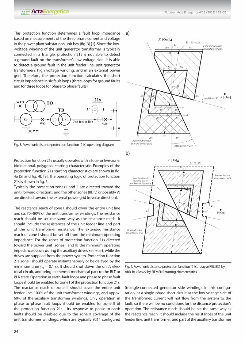
This protection function determines a fault loop impedance based on measurements of the three phase current and voltage in the power plant substation’s unit bay (fi g. 3) [1]. Since the low--voltage winding of the unit generator transformer is typically connected in a triangle, protection 21s is not able to detect a ground fault on the transformer’s low voltage side. It is able to detect a ground fault in the unit feeder line, unit generator transformer’s high voltage winding, and in an external power grid. Therefore, the protection function calculates the short circuit impedance in six fault loops (three loops for ground faults and for three loops for phase to phase faults).
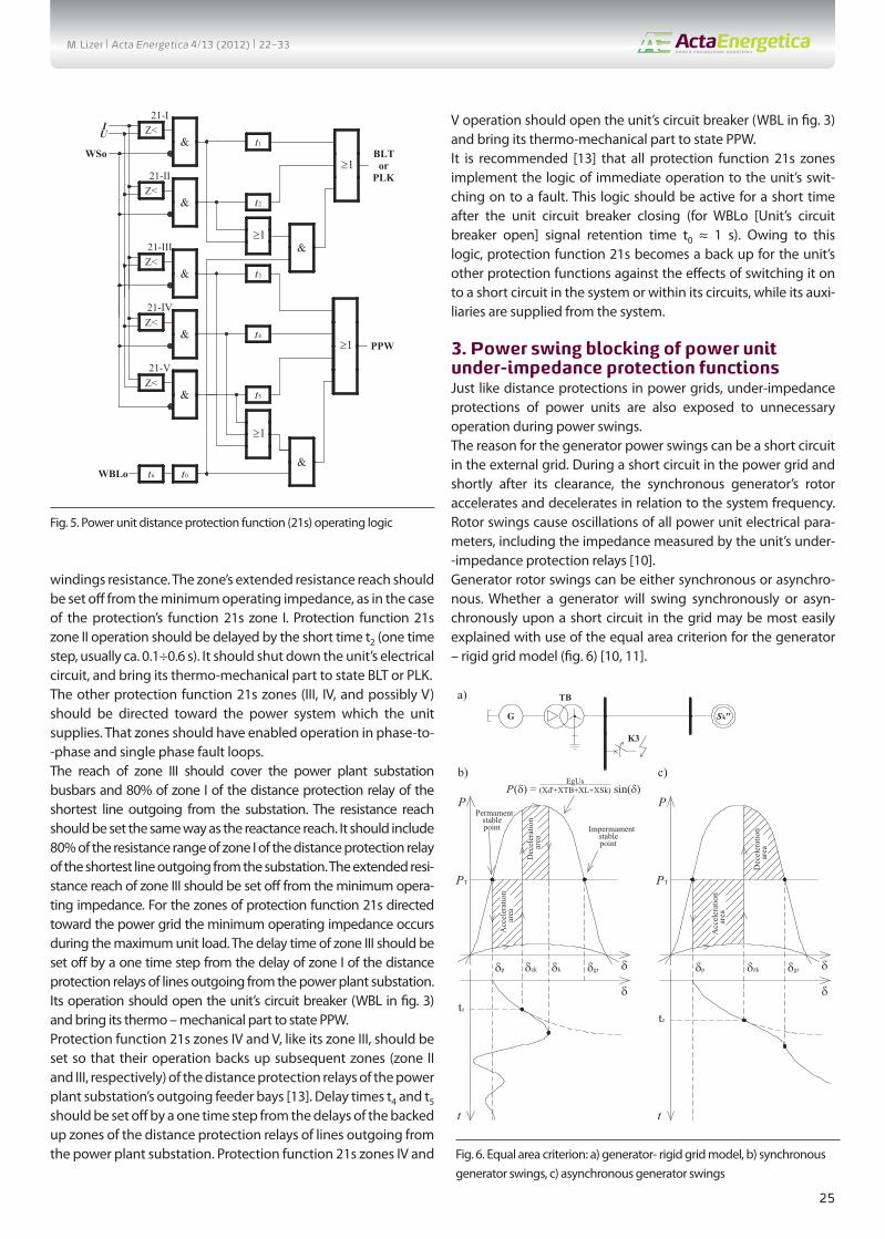
Protection function 21s usually operates with a four- or fi ve-zone, bidirectional, polygonal starting characteristic. Examples of the protection function 21s starting characteristics are shown in fi g. 4a [5] and fi g. 4b [9]. The operating logic of protection function 21s is shown in fi g. 5.Typically the protection zones I and II are directed toward the unit (forward direction), and the other zones (III, IV, or possibly V) are directed toward the external power grid (reverse direction).
The reactance reach of zone I should cover the entire unit line and ca. 70÷80% of the unit transformer windings. The resistance reach should be set the same way as the reactance reach. It should include the resistances of the unit feeder line and part of the unit transformer resistance. The extended resistance reach of zone I should be set off from the minimum operating impedance. For the zones of protection function 21s directed toward the power unit (zones I and II) the minimum operating impedance occurs during the auxiliary drives’ self-start, while the drives are supplied from the power system. Protection function 21s zone I should operate instantaneously or be delayed by the minimum time (t1 = 0.1 s). It should shut down the unit’s elec-trical circuit, and bring its thermo-mechanical part to the BLT or PLK state. Operation in earth-fault loops and phase to phase fault loops should be enabled for zone I of the protection function 21s.The reactance reach of zone II should cover the entire unit feeder line, 100% of the unit transformer windings, and appox. 60% of the auxiliary transformer windings. Only operation in phase to phase fault loops should be enabled for zone II of the protection function 21s . Its response to phase-to-earth faults should be disabled due to the zone II coverage of the unit transformer windings, which are typically Yd11 confi gured
(triangle-connected generator side winding). In this confi gu-ration, at a single-phase short circuit at the low-voltage side of the transformer, current will not fl ow from the system to the fault, so there will be no conditions for the distance protection’s operation. The resistance reach should be set the same way as the reactance reach. It should include the resistances of the unit feeder line, unit transformer, and part of the auxiliary transformer
WTO
WW
WG Unit feeder line
TBTO
GWBL
U I
21s
Fig. 3. Power unit distance protection function (21s) operating diagram
a) X [Om]
R [Om]ArgDir = 15°
ArgNegRes = 25°
RF2 RF2Forward direction
(toward power unit)
Reverse direction(toward power grid)
RF2RF1
RF1 RF1
RL
ZL = RL + jX L
X L1
X L2
RF3RF5
RF5
RF3 RF3
RF5
X L3
X L5
RF4
X L4
RF4 RF4
L
φ
b)
R [Om]
X [Om]
X L1
X L2
X L3
L
RLOAD
X L5
R1 R2R3R5 R1B
X L1B
ZL = RL + jX L
RL
Zone 5 additional operating area at
non-directional operation
R4
X L4
LOAD
Forward direction(toward power unit)
Reverse direction(toward power grid)
φ φ
Fig. 4. Power unit distance protection function (21s), relay a) REL 531 by ABB, b) 7SA522 by SIEMENS starting characteristics
M. Lizer | Acta Energetica 4/13 (2012) | 22–33
25
windings resistance. The zone’s extended resistance reach should be set off from the minimum operating impedance, as in the case of the protection’s function 21s zone I. Protection function 21s zone II operation should be delayed by the short time t2 (one time step, usually ca. 0.1÷0.6 s). It should shut down the unit’s electrical circuit, and bring its thermo-mechanical part to state BLT or PLK.The other protection function 21s zones (III, IV, and possibly V) should be directed toward the power system which the unit supplies. That zones should have enabled operation in phase-to--phase and single phase fault loops.The reach of zone III should cover the power plant substation busbars and 80% of zone I of the distance protection relay of the shortest line outgoing from the substation. The resistance reach should be set the same way as the reactance reach. It should include 80% of the resistance range of zone I of the distance protection relay of the shortest line outgoing from the substation. The extended resi-stance reach of zone III should be set off from the minimum opera-ting impedance. For the zones of protection function 21s directed toward the power grid the minimum operating impedance occurs during the maximum unit load. The delay time of zone III should be set off by a one time step from the delay of zone I of the distance protection relays of lines outgoing from the power plant substation. Its operation should open the unit’s circuit breaker (WBL in fi g. 3) and bring its thermo – mechanical part to state PPW.Protection function 21s zones IV and V, like its zone III, should be set so that their operation backs up subsequent zones (zone II and III, respectively) of the distance protection relays of the power plant substation’s outgoing feeder bays [13]. Delay times t4 and t5 should be set off by a one time step from the delays of the backed up zones of the distance protection relays of lines outgoing from the power plant substation. Protection function 21s zones IV and
V operation should open the unit’s circuit breaker (WBL in fi g. 3) and bring its thermo-mechanical part to state PPW.It is recommended [13] that all protection function 21s zones implement the logic of immediate operation to the unit’s swit-ching on to a fault. This logic should be active for a short time after the unit circuit breaker closing (for WBLo [Unit’s circuit breaker open] signal retention time t0 ≈ 1 s). Owing to this logic, protection function 21s becomes a back up for the unit’s other protection functions against the eff ects of switching it on to a short circuit in the system or within its circuits, while its auxi-liaries are supplied from the system.
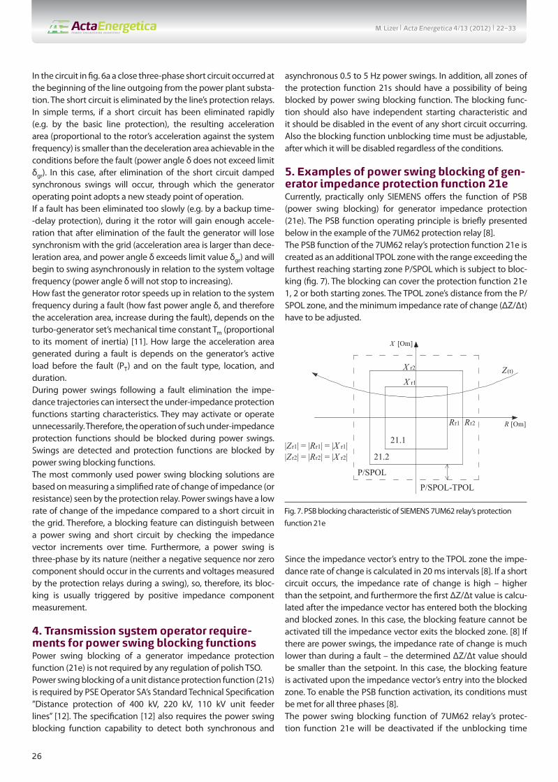
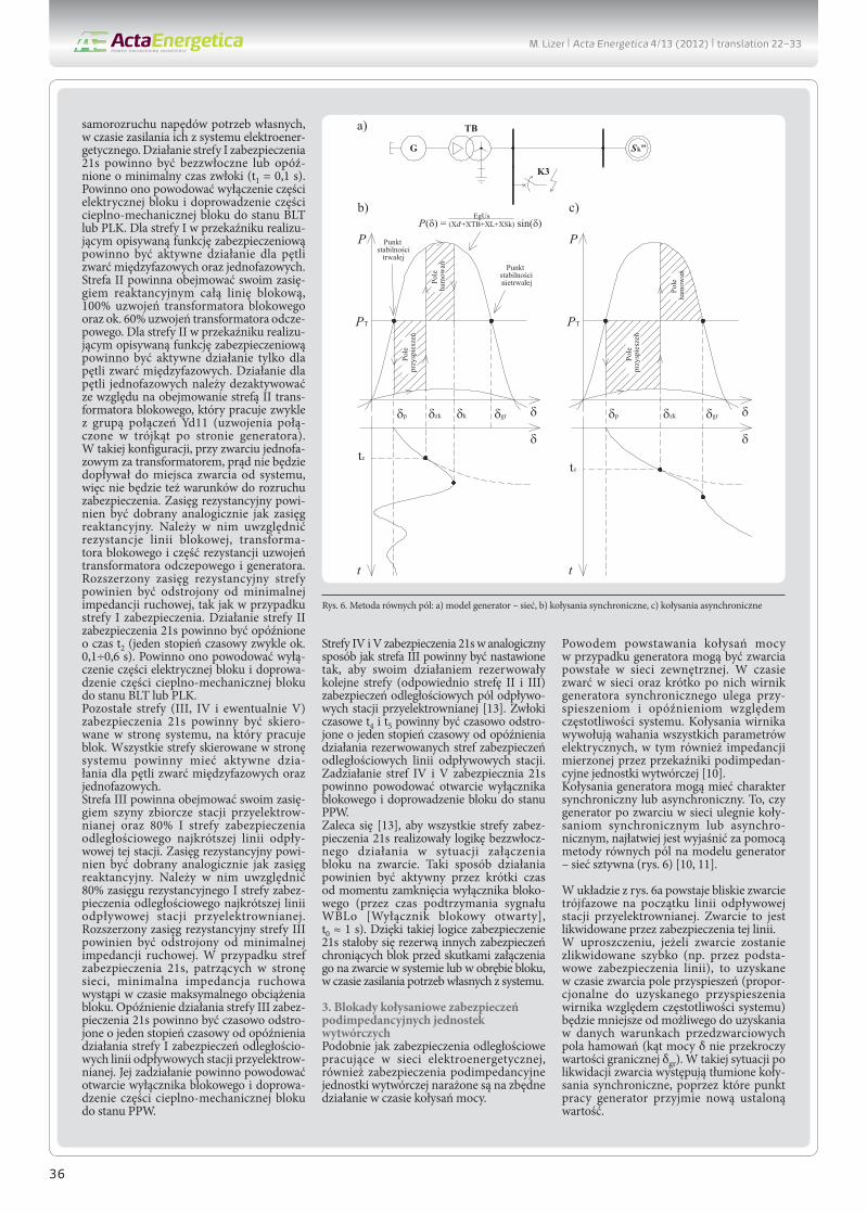
3. Power swing blocking of power unit under-impedance protection functionsJust like distance protections in power grids, under-impedance protections of power units are also exposed to unnecessary operation during power swings.The reason for the generator power swings can be a short circuit in the external grid. During a short circuit in the power grid and shortly after its clearance, the synchronous generator’s rotor accelerates and decelerates in relation to the system frequency. Rotor swings cause oscillations of all power unit electrical para-meters, including the impedance measured by the unit’s under--impedance protection relays [10].Generator rotor swings can be either synchronous or asynchro-nous. Whether a generator will swing synchronously or asyn-chronously upon a short circuit in the grid may be most easily explained with use of the equal area criterion for the generator – rigid grid model (fi g. 6) [10, 11].
BLTor
PLK
t1
Z<21-I
IU
&WSo
&
21-IIZ<
t2
≥1
≥1t4
Z<21-IV
&
&
21-IIIZ<
t3
PPW
&
21-VZ<
t5
≥1
&t0WBLo t6
&≥1
Fig. 5. Power unit distance protection function (21s) operating logic
δδzk δgrδp
P
PT
G
TB
Sk"
K3
δk δ
P
PT
δ
t
tz
δ
t
tz
δgrδp δzk
b) c)
a)
P(δ) = EgUs
(Xd'+XTB+XL+XSk) sin(δ)
Permament stable point Impermament
stable point
Acc
eler
atio
n ar
ea
Acc
eler
atio
n ar
ea
Dec
eler
atio
n ar
ea
Dec
eler
atio
n ar
ea
Fig. 6. Equal area criterion: a) generator- rigid grid model, b) synchronous generator swings, c) asynchronous generator swings
M. Lizer | Acta Energetica 4/13 (2012) | 22–33
26
In the circuit in fi g. 6a a close three-phase short circuit occurred at the beginning of the line outgoing from the power plant substa-tion. The short circuit is eliminated by the line’s protection relays.In simple terms, if a short circuit has been eliminated rapidly (e.g. by the basic line protection), the resulting acceleration area (proportional to the rotor’s acceleration against the system frequency) is smaller than the deceleration area achievable in the conditions before the fault (power angle δ does not exceed limit δgr). In this case, after elimination of the short circuit damped synchronous swings will occur, through which the generator operating point adopts a new steady point of operation.If a fault has been eliminated too slowly (e.g. by a backup time--delay protection), during it the rotor will gain enough accele-ration that after elimination of the fault the generator will lose synchronism with the grid (acceleration area is larger than dece-leration area, and power angle δ exceeds limit value δgr) and will begin to swing asynchronously in relation to the system voltage frequency (power angle δ will not stop to increasing).How fast the generator rotor speeds up in relation to the system frequency during a fault (how fast power angle δ, and therefore the acceleration area, increase during the fault), depends on the turbo-generator set’s mechanical time constant Tm (proportional to its moment of inertia) [11]. How large the acceleration area generated during a fault is depends on the generator’s active load before the fault (PT) and on the fault type, location, and duration.During power swings following a fault elimination the impe-dance trajectories can intersect the under-impedance protection functions starting characteristics. They may activate or operate unnecessarily. Therefore, the operation of such under-impedance protection functions should be blocked during power swings. Swings are detected and protection functions are blocked by power swing blocking functions.The most commonly used power swing blocking solutions are based on measuring a simplifi ed rate of change of impedance (or resistance) seen by the protection relay. Power swings have a low rate of change of the impedance compared to a short circuit in the grid. Therefore, a blocking feature can distinguish between a power swing and short circuit by checking the impedance vector increments over time. Furthermore, a power swing is three-phase by its nature (neither a negative sequence nor zero component should occur in the currents and voltages measured by the protection relays during a swing), so, therefore, its bloc-king is usually triggered by positive impedance component measurement.
4. Transmission system operator require-ments for power swing blocking functionsPower swing blocking of a generator impedance protection function (21e) is not required by any regulation of polish TSO.Power swing blocking of a unit distance protection function (21s) is required by PSE Operator SA’s Standard Technical Specifi cation ”Distance protection of 400 kV, 220 kV, 110 kV unit feeder lines” [12]. The specifi cation [12] also requires the power swing blocking function capability to detect both synchronous and
asynchronous 0.5 to 5 Hz power swings. In addition, all zones of the protection function 21s should have a possibility of being blocked by power swing blocking function. The blocking func-tion should also have independent starting characteristic and it should be disabled in the event of any short circuit occurring. Also the blocking function unblocking time must be adjustable, after which it will be disabled regardless of the conditions.
5. Examples of power swing blocking of gen-erator impedance protection function 21eCurrently, practically only SIEMENS off ers the function of PSB (power swing blocking) for generator impedance protection (21e). The PSB function operating principle is briefl y presented below in the example of the 7UM62 protection relay [8].The PSB function of the 7UM62 relay’s protection function 21e is created as an additional TPOL zone with the range exceeding the furthest reaching starting zone P/SPOL which is subject to bloc-king (fi g. 7). The blocking can cover the protection function 21e 1, 2 or both starting zones. The TPOL zone’s distance from the P/SPOL zone, and the minimum impedance rate of change (ΔZ/Δt) have to be adjusted.
Since the impedance vector’s entry to the TPOL zone the impe-dance rate of change is calculated in 20 ms intervals [8]. If a short circuit occurs, the impedance rate of change is high – higher than the setpoint, and furthermore the fi rst ΔZ/Δt value is calcu-lated after the impedance vector has entered both the blocking and blocked zones. In this case, the blocking feature cannot be activated till the impedance vector exits the blocked zone. [8] If there are power swings, the impedance rate of change is much lower than during a fault – the determined ΔZ/Δt value should be smaller than the setpoint. In this case, the blocking feature is activated upon the impedance vector’s entry into the blocked zone. To enable the PSB function activation, its conditions must be met for all three phases [8].The power swing blocking function of 7UM62 relay’s protec-tion function 21e will be deactivated if the unblocking time
Rr2
|Zr2| = |Rr2| = |X r2||Zr1| = |Rr1| = |X r1|
Rr1
X r1
X [Om]
R [Om]
21.1
21.2
X r2
P/SPOL
P/SPOL-TPOL
Z(t)
Fig. 7. PSB blocking characteristic of SIEMENS 7UM62 relay’s protection function 21e
M. Lizer | Acta Energetica 4/13 (2012) | 22–33

27
(adjustable T-ACTION P/S) has run out, or the impedance vector has left the blocked zones, or the measured impedance change rate has increased over the setpoint, or if in the current measured by the relay a negative sequence component has appeared, which can mean that an asymmetric short circuit has developed [8].
6. Power swing blocking of power unit distance protection function(21s)The power swing blocking function for power unit distance protections is off ered by almost all relay manufacturers. The most commonly used solutions, as in the case of protection function 21e power swing blocking, are those based on measurement of the impedance rate of change or the impedance increments. Two types of PSB functions based on these principles are presented below.
ABB in its REL 531 protection relay off ers a PSD (power swing detection) function. Its starting characteristics are shown in fi g. 8a [5].The REL 531 power swing detection function consists in two addi-tional rectangular zones with a range beyond the blocked zones. The function settings determine the inner zone’s resistance and reactance reach, and KR and KX coeffi cients that denote the outer zone’s reach. From the impedance vector’s entry to the outer PSD zone, time Δt is counted until its entry to the inner PSD zone. If the measured time Δt is shorter than the setpoint, the function recognizes it as a short circuit occurrence. If time Δt is longer than the setpoint, the PSD function is activated [5].The PSD function of REL 531 relay has two adjustable Δt times: tP1, measured at the impedance trajectory’s fi rst pass through PSD zones, and tP2, measured at subsequent passes. The bloc-king feature treats a series of PSD zones’ activations as one event if the time interval between them is shorter than tH. If the time interval activations is longer than tH, the PSB function status is reset (at the next activation time tP1 will again be compared with the measured pass time) [5].The PSD function is deactivated when the unblocking time (primary tR2 or secondary tR1, counted instead of tR2 if a zero current component appears while the blocking feature is on) has expired, or when the impedance vector has left both PSB zones. If prior to PSD activation a zero component has appeared in the current measured by REL 531 relay, the blocking will not be acti-vated [5].SIEMENS off ers a PSD (power swing detection) function in its 7SA522 protection relay with the starting characteristics shown in fi g. 8b [9]. The blocking function consists of an additional PPOL polygonal zone set off from the blocked zone with the largest range (APOL). For the blocking purpose the APOL zone is treated as non-directional. The distance between PPOL and APOL zones is not adjustable and depends on the rated current setting of current transformers (Zdiff = 1 Ω or 5 Ω). From the impedance vector’s entry into the PPOL zone, resistance increments dR and reactance increments dX are calculated in a 5 ms window. On the basis of the determined increments the following blocking criteria are checked [9]:1. Are the impedances measured in the three phases symme-
trical (neither zero, nor negative sequence impedance component)?
2. Is the impedance step changing (or are increments too large compared to to increments measured before)?
3. Is the impedance vector movement direction changing in the R axis (is the movement monotonic)?
4. Is the impedance trajectory situated in the local instability area?
The blocking function is activated for each phase individually if all the criteria are met for it for at least six successive measured incre-ments. [9] The blocking activation conditions are checked until the impedance vector leaves the PPOL zone. The blocking activa-tion will be reset after leaving the PPOL zone or when criteria 1 or 2 are no longer met. However, while the blocking function is set and the criteria are no longer met or the impedance vector has
a) X [Om]
R [Om]RF1
X L1
X L2
RF3RF5
X L3
X L5
RF4
X L4
L
RL
RF2
X1IN
KX·X1IN
-X1IN
-KX·X1IN
R1IN
KR·R1IN-R1IN-KR·R1IN
(2)(1)
Forward direction(toward power unit)
Reverse direction(toward power grid)
b)
R [Om]
X [Om]
X L1
X L2
X L3
ϕL
RLOAD
ϕLOAD
X L5
R1 R2R3
R5 = RA
R4
X L4
APOL
PPOL
RP
RPR5 = RA
(1)(2)
Forward direction(toward power unit)
Reverse direction(toward power grid)
Fig. 8. Starting characteristics of power swing blocking function of power unit distance protection (21s): a) REL 531 by ABB, b) 7SA522 by SIEMENS
M. Lizer | Acta Energetica 4/13 (2012) | 22–33

28
left the PPOL zone, the function will stay on until the end of the adjustable unblocking time (68 Trip Delay) [9].
7. Danger of unnecessary operation of power unit under-impedance protection after slowly eliminated faults in external gridAs noted earlier, following a short circuit in an external grid the generator is exposed to synchronous and asynchronous swings of its rotor relative to the grid frequency. Whether following a fault the generator loses synchronism and will swing asynchro-nously relative to the system depends on the turbo-generator sets inertia, generator load before the fault, and the fault loca-tion, type and duration [10, 11].As shown in the power system model studies [13] and accor-ding to the two-machine model research (like in fi g. 6a) [14], synchronous generator rotor swings following a quickly elimi-nated short circuit in the power grid (usually with elimination time tz < 125 ms), do not threaten an unnecessary activation and operation of the generator impedance protection function (21e) and unit distance protection function (21s). This situation is illu-strated by the following exemplary impedance trajectories seen by protection functions 21e (fi g. 9a) and 21s (fi g. 9b).
In fi g. 9 impedance samples are calculated from samples of RMS currents and voltages, and the phase shift between them.If a short circuit in a grid lasts long enough that after its elimi-nation a generator loses synchronism with the power grid and starts swinging asynchronously, both protection function 21e zones can be activated. Also, an unnecessary tripping of protec-tion 21e zone 21.2 may occur – this zone is operating instantane-ously, or with minimal time delay. In this case both zones directed toward power unit of distance protection function 21s may also be activated. Zone I may unnecessarily trip – it is operating instantaneously, or with a small time delay. Unwanted tripping of the protection functions may occur, especially if the grid’s short circuit power was small before and after the fault. This situation is illustrated by the following exemplary impedance trajectories seen by protection functions 21e (fi g. 10a) and 21s (fi g. 10b).An unnecessary operation of protection functions 21e or 21s for asynchronous generator swings is bad for the system. As a result of that unnecessary tripping the unit is brought to state BLT or PLK. This extends the unit restart time and creates the risk of blackout due to a power defi cit in the system [10]. In this situ-ation, the unit should be cut off from the power grid and brought to state PPW by a pole slip protection (78). This action allows
a)
b)
Fig. 9. Synchronous impedance swings developed after a quickly eliminated, close, three-phase short circuit in the external power grid (tz = 100 ms), seen by protection functions: a) generator impedance protection function 21e, b) unit distance protection function 21s unit distance protection (21s): a) REL 531 by ABB, b) 7SA522 by SIEMENS
M. Lizer | Acta Energetica 4/13 (2012) | 22–33

29
quickly restarting the unit after loss of synchronism. In addition, protection 78 sends trip signals at times more convenient to the circuit breakers [3, 4, 6, 7, 8].In the above situation, the zones of protection function 21e (zone 21.2) and 21s (zone I) exposed to unnecessary opera-tion should be blocked by a power swing blocking function. Simulation studies [13, 14] indicate, however, that the available power swing blocking functions based on the impedance rate of change measurement (or rather on calculation of the resistance and reactance increments in specifi c time intervals, or duration measurement of the impedance vectors’ transition between zones) may not be able to correctly identify starting of asynchro-nous generator swings after a long-lasting short circuit in the power grid.
The highest risk of an unnecessary tripping of the aforementioned protection functions 21e and 21s zones is in the fi rst moment after the short circuit elimination, when the impedance vector can abruptly move to the vicinity of point (0, 0) in the impedance plane, and then start asynchronous swinging. In this situation the impedance vector after the short circuit may abruptly move into protection function 21e zone 21.2 or protection function 21s zone I, and stay there long enough to cause an unwanted operation of these protections. In this part of the circle made by vector Z(t) during asynchronous swings the impedance rate of change is the lowest in the whole asynchronous rotation period (the lower it will be, the smaller in this situation is the diff erence between the acce-leration area generated during the short circuit and the decelera-tion area available in these conditions after the short circuit) [14].
a)
Fig. 10. Asynchronous impedance swings developed after a slowly eliminated, close, three-phase short circuit in the power grid (tz = 300 ms), seen by protection functions: a) generator impedance protection function 21e, b) unit distance protection function 21s
b)
Fig. 11. Asynchronous swings after slowly eliminated, close, three-phase short circuit in the power grid, seen by protection function 21e: a) step transition to zone 21.2, b) entry to zone 21.2 from zone 21.1
a) b)
M. Lizer | Acta Energetica 4/13 (2012) | 22–33

30
With regard to PSB function available for protection function 21e, the following two confi guration options should be considered. In the fi rst option both 21e zones can be blocked. Upon deve-lopment of asynchronous swings after the elimination of a short circuit situated in zone 21.1, after the short circuit the impedance vector may not leave zone 21.1, but abruptly move to zone 21.2 (as shown in fi g. 11a) or in its vicinity, and enter it during the fi rst asynchronous rotation development (as shown in fi g. 11b). In this situation, even if the blocking criteria are met, its response is not possible (after activation of zone 21.1 by a short circuit the impedance vector has not left it after the fault elimination – the blocking feature may conclude that the short circuit persists in zone 21.1) and zone 21.2 may unnecessarily respond after the short circuit disappears.In the other confi guration option of protection function 21e blocking by PSB function it covers only the un-delayed zone 21.2. In this case, there is a risk that the blocking conditions are satisfi ed practically after each three phase short circuit in zone 21.1 lasting for more than 20 ms (duration of ΔZ / DT determining interval [8]), since the impedance rate of change during a short circuit will be practically nil, and the impedance vector will stay inside the blocking zone and outside the blocked zone. In this situation, if a three-phase short circuit develops within the unit’s low voltage circuits while zone 21.1 is activated, zone 21.2 will probably be unnecessarily blocked. This confi guration therefore carries the theoretical risk of missing zone 21.2 operation.In a unit distance protection function 21s power swing blocking function based on duration measurement of the impedance trajectory transit between additional under-impedance zones (e.g. REL 531 relay by ABB) while asynchronous generator swings are developing after a short circuit in the external power grid (in protection zones III, IV or V), the impedance vector may not go beyond the blocking zones, but straight away move to the
vicinity of the protection’s starting characteristics of zones I and II (fi g. 12a). In this situation the blocking feature may not be able to detect asynchronous swings following a long eliminated short circuit until the start of the second asynchronous rotation period – the fast zone I and II of protection function 21s may operate unnecessarily after elimination of the grid fault. This situation is all the more likely, the lower the system’s short circuit power, and the lower the turbo-generator set’s mechanical time constant is.In a protection 21s power swing blocking function based on measurement of the increments of resistance (dR) and reac-tance (dX) within specifi ed time intervals (e.g. 5 ms) and chec-king on this basis the power swing distinguishing criteria (e.g. in 7SA522 relay by SIEMENS) while asynchronous generator swings are developing after a short circuit in the grid (in protec-tion zones III, IV or V), after the fault elimination the impedance vector may move to the protection’s fast zone I quickly enough (abruptly) that the blocking feature will not be able in the mean-time to update the dX dR increments (fi g. 12b). In this situation the blocking function may not be able to block protection func-tion21s, allowing for an unwanted operation of its zone I after the grid fault is eliminated. Also in this case the discussed situation is all the more likely, the lower the system’s short circuit power, and the lower the turbo generator set’s mechanical time constant is.
8. Influence of impedance calculation algo-rithm on the risk of generator under-imped-ance protection functions unnecessary oper-ation in the circumstances of asynchronous power swingsThe impedance trajectories shown above were derived (to simplify the analysis) from the samples of RMS currents and voltages, and from the phase shift between them. This approach allows tracking the impedance trajectory seen, so to speak, on
Fig. 12. Protection function 21s power swing blocking function response to asynchronous swings after a slowly switched off close three-phase short circuit in the grid: a) based on duration of impedance transit between additional zones, b) based on dR and dX increments
a) b)
M. Lizer | Acta Energetica 4/13 (2012) | 22–33
31
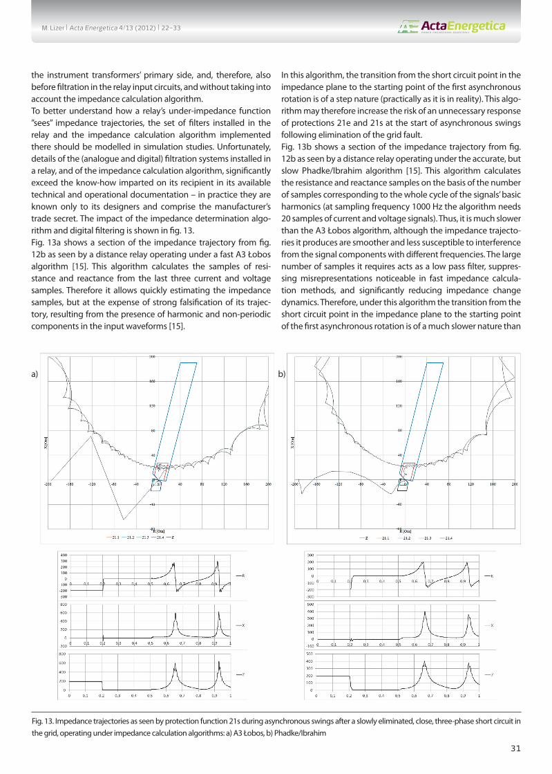
the instrument transformers’ primary side, and, therefore, also before fi ltration in the relay input circuits, and without taking into account the impedance calculation algorithm.To better understand how a relay’s under-impedance function ”sees” impedance trajectories, the set of fi lters installed in the relay and the impedance calculation algorithm implemented there should be modelled in simulation studies. Unfortunately, details of the (analogue and digital) fi ltration systems installed in a relay, and of the impedance calculation algorithm, signifi cantly exceed the know-how imparted on its recipient in its available technical and operational documentation – in practice they are known only to its designers and comprise the manufacturer’s trade secret. The impact of the impedance determination algo-rithm and digital fi ltering is shown in fi g. 13.Fig. 13a shows a section of the impedance trajectory from fi g. 12b as seen by a distance relay operating under a fast A3 Łobos algorithm [15]. This algorithm calculates the samples of resi-stance and reactance from the last three current and voltage samples. Therefore it allows quickly estimating the impedance samples, but at the expense of strong falsifi cation of its trajec-tory, resulting from the presence of harmonic and non-periodic components in the input waveforms [15].
In this algorithm, the transition from the short circuit point in the impedance plane to the starting point of the fi rst asynchronous rotation is of a step nature (practically as it is in reality). This algo-rithm may therefore increase the risk of an unnecessary response of protections 21e and 21s at the start of asynchronous swings following elimination of the grid fault.Fig. 13b shows a section of the impedance trajectory from fi g. 12b as seen by a distance relay operating under the accurate, but slow Phadke/Ibrahim algorithm [15]. This algorithm calculates the resistance and reactance samples on the basis of the number of samples corresponding to the whole cycle of the signals’ basic harmonics (at sampling frequency 1000 Hz the algorithm needs 20 samples of current and voltage signals). Thus, it is much slower than the A3 Łobos algorithm, although the impedance trajecto-ries it produces are smoother and less susceptible to interference from the signal components with diff erent frequencies. The large number of samples it requires acts as a low pass fi lter, suppres-sing misrepresentations noticeable in fast impedance calcula-tion methods, and signifi cantly reducing impedance change dynamics. Therefore, under this algorithm the transition from the short circuit point in the impedance plane to the starting point of the fi rst asynchronous rotation is of a much slower nature than
Fig. 13. Impedance trajectories as seen by protection function 21s during asynchronous swings after a slowly eliminated, close, three-phase short circuit in the grid, operating under impedance calculation algorithms: a) A3 Łobos, b) Phadke/Ibrahim
a) b)
M. Lizer | Acta Energetica 4/13 (2012) | 22–33

32
when using the A3 Łobos algorithm (this is a falsifi cation caused by the impedance calculation method).This algorithm may, therefore, decrease the risk of an unwanted operation of protection functions 21e and 21s at the start of asynchronous swings following the grid fault elimination. This is because it provides the opportunity of activation of power swing blocking function based on calculating the resistance and reac-tance increments (the relay “see” that after a fault the impedance vector doesn’t immediately move to the endangered zones, the algorithm will starch that transient state in time). A blocking feature based on verifi cation of the transition duration between additional zones will still be exposed to the failure to detect swings at the fi rst asynchronous rotation. A disadvantage of this impedance calculation method is relay tripping self time extension.
9. SummaryPower units are protected with the following under-impedance solutions: generator impedance protections function (21e) and unit distance protections function (21s). These are backup protections of a power unit and unit feeder line against the eff ects of short circuits within the unit or the line. They are also basic protections of a unit against the eff ects of short circuits in the power plant substation or external power grid. These protec-tions can interoperate with a power swing blocking function based on, for example, determining the rate of change of the impedance calculated by the relay.The reason for power swing blocking of the under-impedance protections is the risk of their unnecessary operation in the circumstances of power swings following a short circuit in the external grid.Based on simulation studies [13, 14] it has been found that during synchronous power swings following a quickly eliminated short circuit in the grid there is no risk of unnecessary activation or trip-ping of protection functions 21e or 21s.If a short circuit in a grid has lasted long enough that after its elimination a generator loses synchronism, there is the risk of unnecessary operation of the protection zones reacting imme-diately or with minimal delay time, as a result of step-relocation of the end of the impedance vector measured by the relay to the vicinity of these zones or inside them.An unnecessary response of protection functions 21e or 21s for asynchronous generator swings is bad for the system. As a result of such an unnecessary tripping the unit’s electrical and thermo--mechanical parts are completely shut down. This extends the restart time and creates the risk of blackout due to power defi cit. In this situation, the unit should be cut off from the power grid by a pole slip protection function (78).There is concern that the power swing blocking solutions currently available for protection functions 21e and 21s may not be able to correctly identify developing asynchronous generator swings following a long-eliminated short circuit in the grid. These blocking functions may not be able to disable the protections allowing their unnecessary tripping, and in other confi gurations they may block them unnecessarily. This will be more likely the
smaller the system’s short circuit power is and the turbine-gene-rator set’s mechanical time constant is.As shown by the cited simulation results, the impedance calcu-lation algorithm and the signal pre-treatment (analogue and digital fi ltering) have a large impact on under-impedance relay performance in the face of the described situation. Fast algori-thms achieve near-real change rate dynamics of the impedance measured by the relay. However, for the same reason they bear the risk of unnecessary response of protection 21e and 21s fast zones at the start of asynchronous swings after too long elimina-tion of a short circuit in the grid. Slower algorithms reduce the change rate dynamics of the impedance measured by the relay, and thus they provide an opportunity for some power swing blocking solutions to correctly detect the onset of asynchronous swings after too long elimination of a fault in the grid, thus redu-cing the risk of unnecessary operation of protection functions 21e and 21s. A disadvantage of such slow methods is extended relay tripping self time.These issues need to be further verifi ed by as accurate as possible simulation studies, and (if possible) with statistical surveys. Statistical surveys would allow verifying simulation test results and determining whether the problems described here occur theoretically only, or also in reality. Verifying the available protec-tion functions 21e and 21s using digital testers by forcing current and voltage waveforms generated in simulation programs (e.g. in Comtrade format) would be very valuable. This would allow taking into account the input signals pre-processing and impe-dance calculation algorithm implemented in tested relays.If the results of the above proposed tests will be negative or not fully satisfactory, an attempt should be made to develop a new operating logic and a new power swing blocking algorithm for protection functions 21e and 21s that would allow for the proper performance of unit under-impedance protections while asyn-chronous generator swings are developing following a slowly eliminated short circuit in the external power grid.
REFERENCES
1. Żydanowicz J., Elektroenergetyczna automatyka zabezpieczeniowa [Automatic protections for power systems], Warsaw, WNT 1966.
2. Winkler W., Wiszniewski A., Automatyka zabezpieczeniowa w sys-temach elektroenergetycznych [Automatic protections in power systems], Warsaw, WNT 1999.
3. Kopex Electric Systems SA, Biblioteka funkcji przekaźników, logiki, pomiarów [Library of protection functions, operating logic, measure-ments], Tychy 2006.
4. Kopex Electric Systems SA, , CZAZ-GT: opis zabezpieczeń [CZAZ-GT: protection functions descriptions], Tychy 2006.
5. ABB, Application manual REL 531 – High speed line distance protec-tion terminal, 2003.
6. ABB, Generator protection IED REG 670 – Technical reference manual, issue 1.1, Sweden.
7. ABB, Mikroprocesorowe zabezpieczenie generatora REG 316*4 [REG 316*4 microprocessor generator protection relay], Warsaw, 1997.
M. Lizer | Acta Energetica 4/13 (2012) | 22–33

33
8. Siemens, SIPROTEC 7UM62 V.4.1 Multifunctional Generator, Motor and Transformer Protection relay, 2002.
9. Siemens, SIPROTEC Distance protection 7SA522 V4.65 and higher – Manual, 2009.
10. Machowski J., Regulacja i stabilność systemu elektroenergetycz-nego [Power system control and stability], Ofi cyna Wydawnicza Politechniki Warszawskiej, Warsaw 2007.
11. Bernas S., Systemy elektroenergetyczne [Power systems], Warsaw, WNT 1982.
12. PSE Operator SA, Standardowe specyfi kacje techniczne: Zabezpieczenie odległościowe linii blokowej 400 kV, 220 kV, 110 kV [Standard Technical Specifi cation “Distance protection of 400 kV, 220 kV, 110 kV unit lines”], Warsaw, Match 2008.
13. Dobrzyński K., Dytry H., Klucznik J., Lizer M., Lubośny Z., Szweicer W., Wróblewska S., Opracowanie katalogu wymagań dla systemów zabezpieczeń elektrycznych generatorów w zakresie stosowanych funkcji i koordynacji ich nastaw z EAZ w sieci przesyłowe – Etap I i II [Catalogue of requirements for generator protection systems with regard to their protection functions and their settings coordination
with power grid protection relays – Stage I and II], an Institute of Power Engineering and Gdańsk University of Technology study commissioned by PSE Operator SA, Warsaw, 2010 (Stage I) and 2011 (Stage II).
14. Dytry H., Lizer M., Szweicer W., Wróblewska S., Koordynacja zabezpieczeń elektroenergetycznych od zakłóceń zewnętrznych generatorów przyłączonych do szyn rozdzielni bezpośrednio oraz przez transformator blokowy z zabezpieczeniami sieci [Coordination of protection functions against external faults of generators con-nected to substation busbars directly or through a unit transformer with grid protection relays, Institute of Power Engineering, statutory study, Warsaw 2011.
15. Nelles D., Opperskalski H., Digitaler Distanzschutz – Verhalten der Algorihmen bei nichtidealen Eingangssignalen, DUV, Wiesbaden 1991.
In this paper information contained in the specifi c protection relays manuals was used.
Marcin Lizer Institute of Power Engineering in Warsaw
e-mail: [email protected]
Graduated from the Faculty of Electrical Engineering at Warsaw University of Technology (2009). Currently works in the Electric Power Engineering Automation
Laboratory of the Institute of Power Engineering in Warsaw. His professional and scientifi c interests include issues related to protection systems of power units,
distributed energy sources and transmission and distribution power grids, as well as issues related to generation stability during disturbances.
M. Lizer | Acta Energetica 4/13 (2012) | 22–33

34
1. WstępSzybko rosnące zapotrzebowanie zakładów przemysłowych i odbiorców komunalnych na energię elektryczną sprawia, że elementy systemu elektroenergetycznego pracują blisko granic dopuszczalnego obciążenia i granic stabilności – do maksimum wyko-rzystywana jest przepustowość linii elek-troenergetycznych i transformatorów, a generatory utrzymują punkty pracy pozostawiające niewielki zapas stabilności na wypadek zakłóceń i zwarć w sieci. Z tych powodów praktycznie każde nieplano-wane wyłączenie elementu sieci przesy-łowej lub bloku elektrowni może zaburzyć stabilność systemu elektroenergetycznego i zainicjować blackout, pozbawiając zasi-lania odbiorców energii elektrycznej. W tej sytuacji jeszcze groźniejsze stają się zbędne działania zabezpieczeń podimpedancyjnych linii, transformatorów i bloków elektrowni. Zabezpieczenia podimpedancyjne narażone są na zbędne działanie w czasie kołysań mocy. Na tę okoliczność wyposaża się je w blokady kołysaniowe, działające zwykle na zasadzie sprawdzania szybkości zmian impedancji widzianej przez przekaźnik zabezpieczeniowy. W artykule przedsta-wiono zasadę działania i sposoby nasta-wiania zabezpieczeń impedancyjnych gene-ratora (21e) i odległościowych bloku (21s). Opisano też zasadę działania najczęściej stosowanych rozwiązań blokad kołysanio-wych tych zabezpieczeń.Na podstawie badań symulacyjnych zauwa-żono, że istnieje ryzyko zbędnego działania zabezpieczeń impedancyjnych generatora i odległościowych bloku w czasie rozwi-jania się kołysań asynchronicznych gene-ratora, następujących po zlikwidowaniu bliskich zwarć w sieci zewnętrznej. Ponadto w badaniach symulacyjnych sprawdzono też, że najpopularniejsze rozwiązania blokad kołysaniowych (bazujące na sprawdzaniu szybkości zmian impedancji) w przypadku zabezpieczeń podimpedancyjnych jedno-stek wytwórczych mogą nie być w stanie
poprawnie rozpoznać rozwijających się asynchronicznych kołysań mocy, zezwalając na zbędne działanie tych zabezpieczeń.
2. Zabezpieczenia podimpedancyjne jednostek wytwórczychBloki energetyczne wyposaża się zwykle w dwa zabezpieczenia podimpedancyjne: zabezpieczenie impedancyjne generatora (21e), wchodzące w skład funkcji zabezpie-czeniowych zaimplementowanych w zespole zabezpieczeniowym w elektrowni, oraz zabezpieczenie odległościowe bloku (21s), zaimplementowane w terminalu zabezpie-czeniowym w polu blokowym stacji przy-elektrownianej [1, 2].
Zabezpieczenie impedancyjne generatora (21e)Zabezpieczenie impedancyjne generatora wchodzi w skład funkcji zabezpieczenio-wych zaimplementowanych w zespole zabezpieczeniowym, zainstalowanym w elektrowni. Jest to rezerwowe zabezpie-czenie bloku i linii blokowej od skutków zwarć międzyfazowych w obrębie bloku, linii blokowej i sieci zewnętrznej [2].
Zabezpieczenie to wyznacza impedancję pętli zwarcia na podstawie pomiaru prądu trójfazowego w punkcie neutralnym genera-tora oraz napięcia trójfazowego na jego zaci-skach (rys. 1a) [1]. Ponieważ punkt neutralny generatora jest odizolowany od ziemi, a dolne uzwojenie transformatora bloko-wego połączone jest zwykle w trójkąt, zabez-pieczenie 21e nie jest w stanie wykrywać zwarć doziemnych w obrębie bloku i sieci zewnętrznej. W związku z tym nie ma potrzeby obliczania impedancji w pętlach zwarć doziemnych, a funkcja zabezpiecze-niowa może wyznaczać impedancję dla każdej fazy oddzielnie (pofazowo).
Zabezpieczenie 21e pracuje zwykle z dwustrefową, bezkierunkową, kołową lub kwadratową charakterystyką rozruchową. Przykładowe charakterystyki rozruchowe zabezpieczenia 21e pokazane są na rys. 1b [3, 4, 5, 6, 7, 8, 9]. Środkowi okręgu lub punktowi przecięcia się przekątnych prosto-kąta odpowiada zwarcie w miejscu pomiaru napięcia – bezpośrednio na zaciskach generatora.
Impedancyjne i odległościowe zabezpieczenia bloku w czasie zakłóceń w sieci zewnętrznej
AutorMarcin Lizer
Słowa kluczoweblok energetyczny, kołysania mocy, stabilność, zabezpieczenia impedancyjne bloku
StreszczenieW artykule przedstawiono problem ryzyka zbędnego działania zabezpieczeń podimpedancyjnych jednostki wytwórczej, w czasie kołysań mocy następujących po długo likwidowanych zwarciach w sieci zewnętrznej. W pierwszej części opisano zabezpieczenie impedancyjne generatora (21e) i odległościowe bloku (21s). Pokazano charakterystyki rozruchowe, logiki działania i sposób nasta-wiania tych zabezpieczeń. Następnie opisano przykładowe (najczęściej stosowane) rozwiązania blokad kołysaniowych zabezpieczeń podimpedancyjnych bloku. Po powyższym wprowadzeniu opisano problematykę zagrożenia zbędnym działaniem szybkodziała-jących stref zabezpieczeń 21e i 21s, jakie powstaje w chwili rozwijania się asynchronicznych kołysań generatora, następujących po przedłużającej się likwidacji zwarć w sieci, na którą pracuje blok. W artykule pokazano też, że dostępne blokady kołysaniowe mogą nie być w stanie poprawnie wykryć opisywanej sytuacji, dopuszczając do zbędnego działania powyższych zabezpieczeń. Pokazano też, jak na trajektorię impedancji widzianą przez przekaźnik wpływa zastosowany algorytm wyznaczania impedancji.
a)
WTO
WW
WG
Linia blokow
a
TBTO
G
WBL
U 21e
I
b) X [Om]
21.1
21.2
Zr1Zr2
ABB, Kopex, Siemens, itp.
Rr2
|Zr2| = |Rr2| = |X r2||Zr1| = |Rr1| = |X r1|
Rr1
X r1
X [Om]
R [Om]R [Om]
21.1
21.2X r2
Siemens
Rys. 1. Zabezpieczenie impedancyjne generatora (21e): a) układ pracy, b) typowe charakterystyki rozruchowe
M. Lizer | Acta Energetica 4/13 (2012) | translation 22–33
PL
This is a supporting translation of the original text published in this issue of “Acta Energetica” on pages 22–33. When referring to the article please refer to the original text.
35
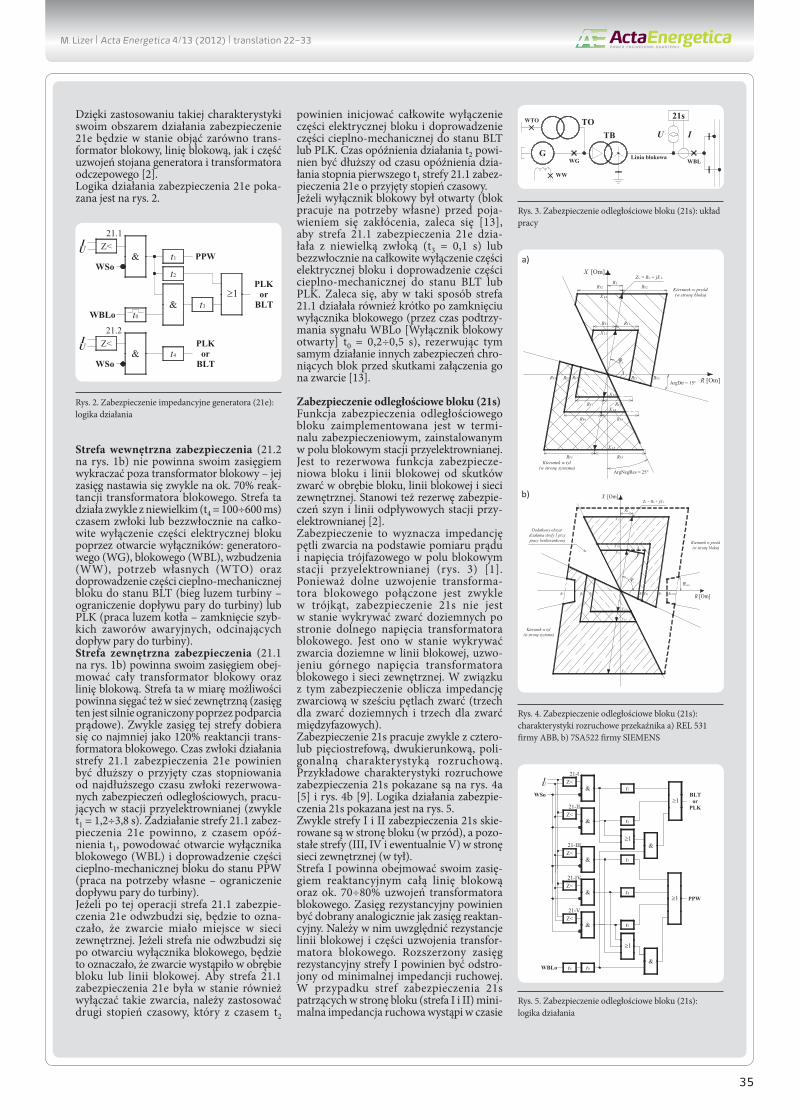
Dzięki zastosowaniu takiej charakterystyki swoim obszarem działania zabezpieczenie 21e będzie w stanie objąć zarówno trans-formator blokowy, linię blokową, jak i część uzwojeń stojana generatora i transformatora odczepowego [2].Logika działania zabezpieczenia 21e poka-zana jest na rys. 2.
Strefa wewnętrzna zabezpieczenia (21.2 na rys. 1b) nie powinna swoim zasięgiem wykraczać poza transformator blokowy – jej zasięg nastawia się zwykle na ok. 70% reak-tancji transformatora blokowego. Strefa ta działa zwykle z niewielkim (t4 = 100÷600 ms) czasem zwłoki lub bezzwłocznie na całko-wite wyłączenie części elektrycznej bloku poprzez otwarcie wyłączników: generatoro-wego (WG), blokowego (WBL), wzbudzenia (WW), potrzeb własnych (WTO) oraz doprowadzenie części cieplno-mechanicznej bloku do stanu BLT (bieg luzem turbiny – ograniczenie dopływu pary do turbiny) lub PLK (praca luzem kotła – zamknięcie szyb-kich zaworów awaryjnych, odcinających dopływ pary do turbiny).Strefa zewnętrzna zabezpieczenia (21.1 na rys. 1b) powinna swoim zasięgiem obej-mować cały transformator blokowy oraz linię blokową. Strefa ta w miarę możliwości powinna sięgać też w sieć zewnętrzną (zasięg ten jest silnie ograniczony poprzez podparcia prądowe). Zwykle zasięg tej strefy dobiera się co najmniej jako 120% reaktancji trans-formatora blokowego. Czas zwłoki działania strefy 21.1 zabezpieczenia 21e powinien być dłuższy o przyjęty czas stopniowania od najdłuższego czasu zwłoki rezerwowa-nych zabezpieczeń odległościowych, pracu-jących w stacji przyelektrownianej (zwykle t1 = 1,2÷3,8 s). Zadziałanie strefy 21.1 zabez-pieczenia 21e powinno, z czasem opóź-nienia t1, powodować otwarcie wyłącznika blokowego (WBL) i doprowadzenie części cieplno-mechanicznej bloku do stanu PPW (praca na potrzeby własne – ograniczenie dopływu pary do turbiny).Jeżeli po tej operacji strefa 21.1 zabezpie-czenia 21e odwzbudzi się, będzie to ozna-czało, że zwarcie miało miejsce w sieci zewnętrznej. Jeżeli strefa nie odwzbudzi się po otwarciu wyłącznika blokowego, będzie to oznaczało, że zwarcie wystąpiło w obrębie bloku lub linii blokowej. Aby strefa 21.1 zabezpieczenia 21e była w stanie również wyłączać takie zwarcia, należy zastosować drugi stopień czasowy, który z czasem t2
powinien inicjować całkowite wyłączenie części elektrycznej bloku i doprowadzenie części cieplno-mechanicznej do stanu BLT lub PLK. Czas opóźnienia działania t2 powi-nien być dłuższy od czasu opóźnienia dzia-łania stopnia pierwszego t1 strefy 21.1 zabez-pieczenia 21e o przyjęty stopień czasowy.Jeżeli wyłącznik blokowy był otwarty (blok pracuje na potrzeby własne) przed poja-wieniem się zakłócenia, zaleca się [13], aby strefa 21.1 zabezpieczenia 21e dzia-łała z niewielką zwłoką (t3 = 0,1 s) lub bezzwłocznie na całkowite wyłączenie części elektrycznej bloku i doprowadzenie części cieplno-mechanicznej do stanu BLT lub PLK. Zaleca się, aby w taki sposób strefa 21.1 działała również krótko po zamknięciu wyłącznika blokowego (przez czas podtrzy-mania sygnału WBLo [Wyłącznik blokowy otwarty] t0 = 0,2÷0,5 s), rezerwując tym samym działanie innych zabezpieczeń chro-niących blok przed skutkami załączenia go na zwarcie [13].
Zabezpieczenie odległościowe bloku (21s)Funkcja zabezpieczenia odległościowego bloku zaimplementowana jest w termi-nalu zabezpieczeniowym, zainstalowanym w polu blokowym stacji przyelektrownianej. Jest to rezerwowa funkcja zabezpiecze-niowa bloku i linii blokowej od skutków zwarć w obrębie bloku, linii blokowej i sieci zewnętrznej. Stanowi też rezerwę zabezpie-czeń szyn i linii odpływowych stacji przy-elektrownianej [2].Zabezpieczenie to wyznacza impedancję pętli zwarcia na podstawie pomiaru prądu i napięcia trójfazowego w polu blokowym stacji przyelektrownianej (rys. 3) [1]. Ponieważ dolne uzwojenie transforma-tora blokowego połączone jest zwykle w trójkąt, zabezpieczenie 21s nie jest w stanie wykrywać zwarć doziemnych po stronie dolnego napięcia transformatora blokowego. Jest ono w stanie wykrywać zwarcia doziemne w linii blokowej, uzwo-jeniu górnego napięcia transformatora blokowego i sieci zewnętrznej. W związku z tym zabezpieczenie oblicza impedancję zwarciową w sześciu pętlach zwarć (trzech dla zwarć doziemnych i trzech dla zwarć międzyfazowych).Zabezpieczenie 21s pracuje zwykle z cztero- lub pięciostrefową, dwukierunkową, poli-gonalną charakterystyką rozruchową. Przykładowe charakterystyki rozruchowe zabezpieczenia 21s pokazane są na rys. 4a [5] i rys. 4b [9]. Logika działania zabezpie-czenia 21s pokazana jest na rys. 5.Zwykle strefy I i II zabezpieczenia 21s skie-rowane są w stronę bloku (w przód), a pozo-stałe strefy (III, IV i ewentualnie V) w stronę sieci zewnętrznej (w tył).Strefa I powinna obejmować swoim zasię-giem reaktancyjnym całą linię blokową oraz ok. 70÷80% uzwojeń transformatora blokowego. Zasięg rezystancyjny powinien być dobrany analogicznie jak zasięg reaktan-cyjny. Należy w nim uwzględnić rezystancje linii blokowej i części uzwojenia transfor-matora blokowego. Rozszerzony zasięg rezystancyjny strefy I powinien być odstro-jony od minimalnej impedancji ruchowej. W przypadku stref zabezpieczenia 21s patrzących w stronę bloku (strefa I i II) mini-malna impedancja ruchowa wystąpi w czasie
PLK or
BLT
PPW
WBLo
≥1t3
t0
&
t2
t1
Z<21.1
IU
&WSo
WSo&
UI
21.2Z<
t4
PLK or
BLT
Rys. 2. Zabezpieczenie impedancyjne generatora (21e): logika działania
WTO
WW
WG Linia blokowa
TBTO
GWBL
U I
21s
Rys. 3. Zabezpieczenie odległościowe bloku (21s): układ pracy
a) X [Om]
R [Om]ArgDir = 15°
ArgNegRes = 25°
RF2 RF2
RF2RF1
RF1 RF1
RL
ZL = RL + jX L
X L1
X L2
RF3RF5
RF5
RF3 RF3
RF5
X L3
X L5
RF4
X L4
RF4 RF4
Lφ
Kierunek w przód(w stronę bloku)
Kierunek w tył(w stronę systemu)
b)
R [Om]
X [Om]
X L1
X L2
X L3
L
RLOAD
X L5
R1 R2R3R5 R1B
X L1B
ZL = RL + jX L
RL
R4
X L4
LOAD
φ φ
Kierunek w przód(w stronę bloku)
Kierunek w tył(w stronę systemu)
Dodatkowy obszar działania strefy 5 przy pracy bezkierunkowej
Rys. 4. Zabezpieczenie odległościowe bloku (21s): charakterystyki rozruchowe przekaźnika a) REL 531 firmy ABB, b) 7SA522 firmy SIEMENS
BLTor
PLK
t1
Z<21-I
IU
&WSo
&
21-IIZ<
t2
≥1
≥1t4
Z<21-IV
&
&
21-IIIZ<
t3
PPW
&
21-VZ<
t5
≥1
&t0WBLo t6
&≥1
Rys. 5. Zabezpieczenie odległościowe bloku (21s): logika działania
M. Lizer | Acta Energetica 4/13 (2012) | translation 22–33
36
samorozruchu napędów potrzeb własnych, w czasie zasilania ich z systemu elektroener-getycznego. Działanie strefy I zabezpieczenia 21s powinno być bezzwłoczne lub opóź-nione o minimalny czas zwłoki (t1 = 0,1 s). Powinno ono powodować wyłączenie części elektrycznej bloku i doprowadzenie części cieplno-mechanicznej bloku do stanu BLT lub PLK. Dla strefy I w przekaźniku realizu-jącym opisywaną funkcję zabezpieczeniową powinno być aktywne działanie dla pętli zwarć międzyfazowych oraz jednofazowych.Strefa II powinna obejmować swoim zasię-giem reaktancyjnym całą linię blokową, 100% uzwojeń transformatora blokowego oraz ok. 60% uzwojeń transformatora odcze-powego. Dla strefy II w przekaźniku realizu-jącym opisywaną funkcję zabezpieczeniową powinno być aktywne działanie tylko dla pętli zwarć międzyfazowych. Działanie dla pętli jednofazowych należy dezaktywować ze względu na obejmowanie strefą II trans-formatora blokowego, który pracuje zwykle z grupą połączeń Yd11 (uzwojenia połą-czone w trójkąt po stronie generatora). W takiej konfiguracji, przy zwarciu jednofa-zowym za transformatorem, prąd nie będzie dopływał do miejsca zwarcia od systemu, więc nie będzie też warunków do rozruchu zabezpieczenia. Zasięg rezystancyjny powi-nien być dobrany analogicznie jak zasięg reaktancyjny. Należy w nim uwzględnić rezystancje linii blokowej, transforma-tora blokowego i część rezystancji uzwojeń transformatora odczepowego i generatora. Rozszerzony zasięg rezystancyjny strefy powinien być odstrojony od minimalnej impedancji ruchowej, tak jak w przypadku strefy I zabezpieczenia. Działanie strefy II zabezpieczenia 21s powinno być opóźnione o czas t2 (jeden stopień czasowy zwykle ok. 0,1÷0,6 s). Powinno ono powodować wyłą-czenie części elektrycznej bloku i doprowa-dzenie części cieplno-mechanicznej bloku do stanu BLT lub PLK.Pozostałe strefy (III, IV i ewentualnie V) zabezpieczenia 21s powinny być skiero-wane w stronę systemu, na który pracuje blok. Wszystkie strefy skierowane w stronę systemu powinny mieć aktywne dzia-łania dla pętli zwarć międzyfazowych oraz jednofazowych.Strefa III powinna obejmować swoim zasię-giem szyny zbiorcze stacji przyelektrow-nianej oraz 80% I strefy zabezpieczenia odległościowego najkrótszej linii odpły-wowej tej stacji. Zasięg rezystancyjny powi-nien być dobrany analogicznie jak zasięg reaktancyjny. Należy w nim uwzględnić 80% zasięgu rezystancyjnego I strefy zabez-pieczenia odległościowego najkrótszej linii odpływowej stacji przyelektrownianej. Rozszerzony zasięg rezystancyjny strefy III powinien być odstrojony od minimalnej impedancji ruchowej. W przypadku stref zabezpieczenia 21s, patrzących w stronę sieci, minimalna impedancja ruchowa wystąpi w czasie maksymalnego obciążenia bloku. Opóźnienie działania strefy III zabez-pieczenia 21s powinno być czasowo odstro-jone o jeden stopień czasowy od opóźnienia działania strefy I zabezpieczeń odległościo-wych linii odpływowych stacji przyelektrow-nianej. Jej zadziałanie powinno powodować otwarcie wyłącznika blokowego i doprowa-dzenie części cieplno-mechanicznej bloku do stanu PPW.
Strefy IV i V zabezpieczenia 21s w analogiczny sposób jak strefa III powinny być nastawione tak, aby swoim działaniem rezerwowały kolejne strefy (odpowiednio strefę II i III) zabezpieczeń odległościowych pól odpływo-wych stacji przyelektrownianej [13]. Zwłoki czasowe t4 i t5 powinny być czasowo odstro-jone o jeden stopień czasowy od opóźnienia działania rezerwowanych stref zabezpieczeń odległościowych linii odpływowych stacji. Zadziałanie stref IV i V zabezpiecznia 21s powinno powodować otwarcie wyłącznika blokowego i doprowadzenie bloku do stanu PPW.Zaleca się [13], aby wszystkie strefy zabez-pieczenia 21s realizowały logikę bezzwłocz-nego działania w sytuacji załączenia bloku na zwarcie. Taki sposób działania powinien być aktywny przez krótki czas od momentu zamknięcia wyłącznika bloko-wego (przez czas podtrzymania sygnału WBLo [Wyłącznik blokowy otwarty], t0 ≈ 1 s). Dzięki takiej logice zabezpieczenie 21s stałoby się rezerwą innych zabezpieczeń chroniących blok przed skutkami załączenia go na zwarcie w systemie lub w obrębie bloku, w czasie zasilania potrzeb własnych z systemu.
3. Blokady kołysaniowe zabezpieczeń podimpedancyjnych jednostek wytwórczychPodobnie jak zabezpieczenia odległościowe pracujące w sieci elektroenergetycznej, również zabezpieczenia podimpedancyjne jednostki wytwórczej narażone są na zbędne działanie w czasie kołysań mocy.
Powodem powstawania kołysań mocy w przypadku generatora mogą być zwarcia powstałe w sieci zewnętrznej. W czasie zwarć w sieci oraz krótko po nich wirnik generatora synchronicznego ulega przy-spieszeniom i opóźnieniom względem częstotliwości systemu. Kołysania wirnika wywołują wahania wszystkich parametrów elektrycznych, w tym również impedancji mierzonej przez przekaźniki podimpedan-cyjne jednostki wytwórczej [10].Kołysania generatora mogą mieć charakter synchroniczny lub asynchroniczny. To, czy generator po zwarciu w sieci ulegnie koły-saniom synchronicznym lub asynchro-nicznym, najłatwiej jest wyjaśnić za pomocą metody równych pól na modelu generator – sieć sztywna (rys. 6) [10, 11].
W układzie z rys. 6a powstaje bliskie zwarcie trójfazowe na początku linii odpływowej stacji przyelektrownianej. Zwarcie to jest likwidowane przez zabezpieczenia tej linii.W uproszczeniu, jeżeli zwarcie zostanie zlikwidowane szybko (np. przez podsta-wowe zabezpieczenia linii), to uzyskane w czasie zwarcia pole przyspieszeń (propor-cjonalne do uzyskanego przyspieszenia wirnika względem częstotliwości systemu) będzie mniejsze od możliwego do uzyskania w danych warunkach przedzwarciowych pola hamowań (kąt mocy δ nie przekroczy wartości granicznej δgr). W takiej sytuacji po likwidacji zwarcia występują tłumione koły-sania synchroniczne, poprzez które punkt pracy generator przyjmie nową ustaloną wartość.
δδzk δgrδp
P
PT
Pole
pr
zysp
iesz
eń
Punkt stabilności
trwałejPunkt
stabilności nietrwałej
G
TB
Sk"
K3
Pole
ha
mow
ań
δk δ
P
PT
Pole
pr
zysp
iesz
eń
Pole
ha
mow
ań
δ
t
tz
δ
t
tz
δgrδp δzk
b) c)
a)
P(δ) = EgUs
(Xd'+XTB+XL+XSk) sin(δ)
Rys. 6. Metoda równych pól: a) model generator – sieć, b) kołysania synchroniczne, c) kołysania asynchroniczne
M. Lizer | Acta Energetica 4/13 (2012) | translation 22–33

37
Jeżeli zwarcie zostanie zlikwidowane zbyt wolno (np. przez rezerwowe, zwłoczne zabezpieczenia), to wirnik nabierze w czasie zwarcia na tyle duże przyspieszenie, że po zlikwidowaniu zwarcia generator utraci synchronizm z siecią (pole przyspieszeń będzie większe od pola hamowań, a kąt mocy δ przekroczy wartość graniczną δgr) i zacznie się kołysać asynchronicznie względem częstotliwości napięcia systemu (kąt mocy δ nie przestanie wzrastać).To jak szybko wirnik generatora przy-spiesza w czasie zwarcia względem często-tliwości systemu (jak szybko zwiększa się w czasie zwarcia kąt mocy δ, a tym samym pole przyspieszeń i pole hamowań), zależy od mechanicznej stałej czasowej turboze-społu T (proporcjonalnej do jego momentu bezwładności) [11]. To, jak duże będzie pole przyspieszeń uzyskane w czasie zwarcia, zależy od tego, jakie było obciążenie czynne generatora przed zwarciem (PT) oraz od typu, lokalizacji i czasu trwania zwarcia.Podczas kołysań mocy następujących po likwidacji zwarć trajektorie impedancji mogą przecinać charakterystyki rozruchowe zabezpieczeń podimpedancyjnych. Może dojść do ich zbędnego pobudzenia się lub działania. Działanie zabezpieczeń podim-pedancyjnych powinno być w związku z tym blokowane w czasie kołysań mocy. Do wykrywania kołysań i blokowania przekaź-ników służą blokady kołysaniowe.Najczęściej stosowane są rozwiązania blokad kołysaniowych bazujące na uproszczonym pomiarze szybkości zmian impedancji lub rezystancji widzianej przez przekaźnik. Kołysania mocy charakteryzują się małą szybkością zmian impedancji w porów-naniu ze zwarciami w sieci. Blokada może zatem rozróżniać kołysania mocy od zwarć poprzez sprawdzanie przyrostów wektora impedancji w czasie. Ponadto kołysania mocy mają charakter trójfazowy (w prądach mierzonych przez zabezpieczenie w czasie kołysań nie powinna pojawiać się skła-dowa przeciwna lub zerowa), w związku z tym blokady działają zwykle na podstawie pomiaru składowej zgodnej impedancji.
4. Wymagania operatora sieci przesyłowej odnośnie stosowania blokad kołysaniowychW zabezpieczeniach impedancyjnych gene-ratora (21e) nie jest obecnie wymagane stosowanie blokad kołysaniowych.W zabezpieczeniach odległościowych bloku (21s) stosowanie blokad kołysaniowych jest wymagane przez Standardową Specyfikację Techniczną „Zabezpieczenie odległościowe linii blokowej 400 kV, 220 kV, 110 kV” PSE SA [12]. Specyfikacja [12] wymaga także, aby blokady kołysaniowe były w stanie wykryć zarówno kołysania synchroniczne, jak i asynchroniczne o częstotliwości 0,5÷5 Hz. Ponadto wszystkie strefy zabezpieczenia 21s powinny mieć możliwość aktywacji blokady o niezależnej charakterystyce rozruchowej i możliwości dezaktywacji w razie poja-wienia się dowolnego zwarcia. Blokada musi mieć też nastawialny czas deblokady, po upływie którego zostanie ona zdjęta nieza-leżnie od panujących warunków.
5. Przykłady blokad kołysaniowych zabezpieczeń impedancyjnych generatora 21eObecnie praktycznie tylko firma SIEMENS oferuje blokadę kołysaniową (PSB, ang. power swing blocking) zabezpieczeń impe-dancyjnych generatora (21e). Poniżej przedstawiono pokrótce zasadę działania tej blokady na przykładzie przekaźnika 7UM62 [8].Blokadę PSB funkcji 21e przekaźnika 7UM62 tworzy dodatkowa strefa TPOL o zasięgu większym od najdalej sięgającej strefy rozruchowej, podlegającej blokowaniu P/SPOL (rys. 7). Blokada może objąć 1, 2 lub obie strefy rozruchowe zabezpieczenia. Nastawiana jest odległość strefy TPOL od największej strefy P/SPOL oraz mini-malna szybkość zmian impedancji (ΔZ/Δt).Od wejścia wektora impedancji do strefy TPOL obliczana jest szybkość zmian impedancji w oknie 20 ms [8]. Jeżeli ma miejsce zwarcie, to szybkość zmian impe-
dancji jest duża – większa od nastawionej wartości, a ponadto pierwsza wartość ΔZ/Δt zostanie obliczona, gdy tylko wektor impedancji znajdować się będzie zarówno w strefie blokady, jak i w strefie blokowanej. W takiej sytuacji aktywacja blokady nie będzie możliwa do chwili opuszczenia strefy blokowanej [8]. Jeżeli mają miejsce koły-sania mocy, to szybkość zmian impedancji jest znacznie mniejsza niż w czasie zwarć – wyznaczona wartość ΔZ/Δt powinna być mniejsza niż wartość nastawiona. W takiej sytuacji blokada zostanie aktywowana, kiedy
wektor impedancji wejdzie w strefę bloko-waną. Aby aktywacja blokady była możliwa, jej warunki muszą być spełnione dla trzech faz [8].Dezaktywacja blokady kołysaniowej funkcji 21e przekaźnika 7UM62 nastąpi, jeśli upłynie czas deblokady (nastawialny T-ACTION P/S) albo wektor impedancji opuści strefy blokowane lub też zmierzona szybkość zmian impedancji zwiększy się ponad nasta-wioną wartość albo jeśli w mierzonym przez przekaźnik prądzie pojawi się składowa przeciwna, mogąca świadczyć o powstaniu zwarcia niesymetrycznego [8].
6. Blokady kołysaniowe zabezpieczeń odległościowych bloku (21s)W przypadku funkcji zabezpieczenia odle-głościowego bloku praktycznie wszyscy producenci przekaźników oferują blokady kołysaniowe. Najczęściej stosowanymi rozwiązaniami, podobnie jak w przypadku blokad zabezpieczeń 21e, są te oparte na sprawdzaniu szybkości zmian impedancji lub na sprawdzaniu wielkości jej przyrostów. Poniżej zostaną przedstawione dwa typy blokad oparte na powyższych zasadach.Firma ABB w przekaźniku REL 531 oferuje blokadę kołysaniową PSD (ang. power swing detection). Charakterystyki rozruchowe blokady pokazano na rys. 8a [5].
Blokadę tworzą dwie dodatkowe prostokątne strefy o zasięgu większym niż blokowane strefy. W nastawieniach blokady określa się zasięg rezystancyjny i reaktancyjny strefy wewnętrznej oraz współczynniki KR i KX, określające zasięg strefy zewnętrznej. Od wejścia wektora impedancji do zewnętrznej strefy PSD zliczany jest czas Δt do wejścia w strefę wewnętrzną. Jeżeli zmierzony czas Δt jest krótszy od nastawionych czasów, blokada uznaje, że ma miejsce zwarcie. Jeśli czas Δt jest większy od nastawionych czasów, blokada jest aktywowana [5].Blokada PSD przekaźnika REL 531 ma nastawialne dwa czasy Δt: tP1, spraw-dzany przy pierwszym przejściu trajektorii impedancji przez strefy PSD, oraz tP2, sprawdzany przy kolejnych przejściach. Blokada traktuje serię pobudzeń stref PSD jako jedno zdarzenie, jeżeli czas przerwy pomiędzy nimi jest krótszy niż czas tH. Jeśli czas przerwy pomiędzy pobudzeniami jest dłuższy od tH, stan blokady jest zerowany
Rr2
|Zr2| = |Rr2| = |X r2||Zr1| = |Rr1| = |X r1|
Rr1
X r1
X [Om]
R [Om]
21.1
21.2
X r2
P/SPOL
P/SPOL-TPOL
Z(t)
Rys. 7. Charakterystyka blokady kołysaniowej funkcji 21e przekaźnika 7UM62 firmy SIEMENS
a) X [Om]
R [Om]RF1
X L1
X L2
RF3RF5
X L3
X L5
RF4
X L4
L
RL
RF2
X1IN
KX·X1IN
-X1IN
-KX·X1IN
R1IN
KR·R1IN-R1IN-KR·R1IN
(2)(1)
b)
R [Om]
X [Om]
X L1
X L2
X L3
ϕL
RLOAD
ϕLOAD
X L5
R1 R2R3
R5 = RA
R4
X L4
APOL
PPOL
RP
RPR5 = RA
(1)(2)
Kierunek w przód(w stronę bloku)
Kierunek w tył(w stronę systemu)
Kierunek w przód(w stronę bloku)
Kierunek w tył
(w stronę systemu)
Rys. 8. Charakterystyki rozruchowe blokad kołysaniowych zabezpieczeń odległościowych bloku (21s): a) REL 531 firmy ABB, b) 7SA522 firmy SIEMENS
M. Lizer | Acta Energetica 4/13 (2012) | translation 22–33

38
(przy następnym pobudzeniu sprawdzany będzie czas tP1) [5].Blokada PSD dezaktywowana jest, kiedy upłynie czas deblokady (podstawowy tR2 lub dodatkowy tR1, odliczany zamiast tR2, jeśli w czasie trwania blokady pojawi się składowa zerowa prądu) lub kiedy wektor impedancji opuści obie strefy blokady. Jeżeli w prądzie mierzonym przez przekaźnik REL 531 przed pobudzeniem blokady PSD pojawiła się składowa zerowa, blokada nie zostanie aktywowana [5].Firma SIEMENS w przekaźniku 7SA522 oferuje blokadę kołysaniową PSD (ang. power swing detection) pracującą z charak-terystykami rozruchowymi pokazanymi na rys. 8b [9].Blokadę tworzy dodatkowa poligonalna strefa PPOL odsunięta od blokowanej strefy o największym zasięgu APOL. Strefa APOL na potrzeby blokady traktowana jest jako bezkierunkowa. Odległość strefy PPOL od APOL jest nienastawialna i zależy od nastawienia prądu znamionowego strony wtórnej przekładników prądowych (Zdiff = 1 Ω / 5 Ω). Od wejścia wektora impedancji do strefy PPOL obliczane są przyrosty rezy-stancji dR i reaktancji dX w oknie 5 ms. Na podstawie wyznaczonych przyrostów spraw-dzane są następujące kryteria blokady [9]:1. Czy impedancje mierzone w trzech fazach
są symetryczne (brak składowej zerowej lub przeciwnej impedancji)
2. Czy nie dochodzi do skokowych zmian impedancji (czy przyrosty nie są zbyt duże)
3. Czy nie zmienia się kierunek ruchu wektora impedancji w osi R (czy ruch jest monotoniczny)
4. Czy trajektoria impedancji lokuje się w obszarze niestabilności lokalnej.
Blokada jest aktywowana indywidualnie dla każdej fazy, jeśli spełnione są dla niej wszystkie kryteria [9]. Warunki aktywacji blokady są sprawdzane, dopóki wektor impe-dancji nie opuści strefy PPOL. Pobudzenie blokady zostanie zresetowane po opusz-czeniu strefy PPOL lub kiedy przestanie być spełniane kryterium 1 lub 2. Jeżeli jednak w trakcie trwania blokady kryteria przestaną być spełniane lub wektor impedancji opuści strefę PPOL, blokada pozostanie utrzymy-wana do upłynięcia nastawialnego czasu deblokady (68 Trip Delay) [9].
7. Zagrożenie zbędnym działaniem zabezpieczeń podimpedancyjnych bloku po długo likwidowanych zwarciach w sieci zewnętrznejJak napisano wcześniej, w następstwie zwarć w sieci zewnętrznej generator narażony jest na synchroniczne i asynchroniczne koły-sania jego wirnika względem częstotliwości sieci. To, czy po zwarciu generator utraci synchronizm i będzie kołysał się asynchro-nicznie względem systemu, zależy od inercji turbozespołu, obciążenia generatora przed zwarciem oraz od lokalizacji, typu i czasu trwania zwarcia [10, 11].Z przeprowadzonych na potrzeby pracy [13] badań na modelu sieci KSE oraz z badań na modelu dwumaszynowym (rys. 6a), przeprowadzonych na potrzeby pracy [14], wynika, że synchroniczne kołysania wirnika generatora, następujące po szybko zlikwido-wanym zwarciu w sieci (zwykle tz < 125 ms), nie zagrażają zbędnym pobudzaniem się i działaniem zabezpieczenia impedancyj-nego generatora (21e) i odległościowego
bloku (21s). Powyższą sytuację ilustrują poniższe trajektorie impedancji widziane przez funkcję 21e (rys. 9a) i 21s (rys. 9b).Na rys. 9 wartości chwilowe impedancji zostały określone na podstawie chwilowych wartości skutecznych prądów, napięć oraz chwilowego przesunięcia fazowego między tymi sygnałami.Jeżeli zwarcie w sieci będzie trwało na tyle długo, że po jego zakończeniu generator utraci synchronizm z siecią i rozpoczną się jego kołysania asynchroniczne, to pobu-dzeniu mogą ulec obie strefy zabezpieczenia 21e. Może też dojść do zbędnego zadziałania, w szczególności strefy 21.2 zabezpieczenia 21e działającej bezzwłocznie lub z minimalnym czasem zwłoki. W przypadku zabezpieczenia odległościowego 21s, w powyższej sytuacji pobudzeniu mogą ulec obie strefy patrzące w stronę bloku. Może dojść do zbędnego działania strefy I działającej bezzwłocznie lub z małym czasem zwłoki, zwłaszcza jeśli
moc zwarciowa sieci przed zwarciem była nieduża. Sytuację tę ilustrują poniższe trajek-torie impedancji widziane przez funkcję 21e (rys. 10a) i 21s (rys. 10b).Zbędne działanie zabezpieczeń 21e lub 21s w czasie kołysań asynchronicznych gene-ratora jest niekorzystne dla pracy systemu. W wyniku jego działania blok doprowadzany jest do stanu BLT lub PLK. Wydłuża to czas restartu bloku i stwarza ryzyko powstania blackoutu na skutek deficytu mocy [10]. W tej sytuacji blok powinien zostać odcięty od sieci i doprowadzony do stanu PPW przez zabezpieczenie od skutków poślizgu biegunów (78). Takie działanie pozwala na szybki restart bloku po utracie synchro-nizmu. Dodatkowo zabezpieczenie 78 wysyła sygnały sterujące w chwili dogodnej dla wyłącznika [3, 4, 6, 7, 8].W powyższej sytuacji narażone na zbędne zadziałanie strefy zabezpieczeń 21e (strefa 21.2) i 21s (strefa I) powinny zostać
Rys. 9. Synchroniczne kołysania impedancji powstałe po szybko wyłączonym, bliskim, trójfazowym zwarciu w sieci (tz = 100 ms), widziane przez zabezpieczenia: a) impedancyjne generatora 21e, b) odległościowe bloku 21s
Rys. 10. Asynchroniczne kołysania impedancji powstałe po powolnie wyłączonym, bliskim, trójfazowym zwarciu w sieci (tz = 300 ms), widziane przez zabezpieczenia: a) impedancyjne generatora 21e, b) odległościowe bloku 21s
M. Lizer | Acta Energetica 4/13 (2012) | translation 22–33
a)
b)
a) b)

39
zablokowane przez blokady kołysaniowe. Badania symulacyjne [13, 14] wskazują jednak na to, że dostępne blokady koły-saniowe opierające się na sprawdzaniu szybkości zmian impedancji (a w zasadzie na obliczaniu przyrostów rezystancji i reak-tancji w określonych oknach czasowych lub sprawdzaniu czasów przejścia wektorów impedancji pomiędzy strefami) mogą nie być w stanie poprawnie rozpoznać rozwi-jania się kołysań asynchronicznych genera-tora po długotrwałym zwarciu w sieci jako kołysań mocy wymagających zablokowania przekaźnika.Największe ryzyko zbędnego działania wymienionych stref zabezpieczeń 21e i 21s powstaje w pierwszej chwili po likwidacji zwarcia, kiedy wektor impedancji może skokowo przemieścić w pobliże punktu (0;0) na płaszczyźnie impedancji, a następnie rozpocząć kołysania asynchroniczne. W tej sytuacji wektor impedancji może po zwarciu skokowo przemieścić się do wnętrza strefy 21.2 zabezpieczenia 21e lub strefy I zabez-pieczenia 21s i pozostać w nich na tyle długo, aby spowodować zbędne działanie tych zabezpieczeń. W omawianej części koła zataczanego przez wektor Z(t) w czasie kołysań asynchronicznych szybkość zmian impedancji jest najmniejsza w całym obrocie asynchronicznym (będzie ona tym mniejsza, im mniejsza będzie w zaistniałej sytuacji różnica powierzchni pola przyspie-szeń uzyskanego w czasie zwarcia i pola hamowań dostępnego w danych warunkach po zwarciu) [14].W przypadku dostępnych dla zabezpie-czenia 21e blokad PSB należy rozpatrzyć dwa przypadki ich konfiguracji. W pierwszym blokada obejmuje obie strefy 21e. W razie rozwoju kołysań asynchronicznych po likwi-dacji zwarcia, które lokowało się w strefie 21.1, wektor impedancji może po zwarciu nie opuścić strefy 21.1, lecz skokowo prze-mieścić się do strefy 21.2 (jak na rys. 11a) lub w jej pobliże i wkroczyć do niej w czasie rozwijania się pierwszego obrotu asynchro-nicznego (jak na rys. 11b). W tej sytuacji nawet jeśli kryteria blokady będą spełnione, to jej aktywacja nie będzie możliwa (po pobudzeniu strefy 21.1 na skutek zwarcia wektor impedancji nie opuścił jej po zlikwi-dowaniu zakłócenia – blokada może uznać, że dalej ma miejsce zwarcie w strefie 21.1)
i strefa 21.2 będzie mogła zadziałać zbędnie już po zaniknięciu zwarcia.W drugiej możliwej konfiguracji blokady PSB zabezpieczenia 21e obejmuje ona tylko bezzwłoczną strefę 21.2. W takim przy-padku istnieje ryzyko, że warunki blokady zostaną spełnione praktycznie po każdym zwarciu trójfazowym w strefie 21.1, trwa-jącym powyżej 20 ms (czas trwania okna wyznaczania ΔZ/Δt [8]), ponieważ szyb-kość zmian impedancji w czasie zwarcia będzie praktycznie zerowa, a wektor impe-dancji będzie przebywał wewnątrz strefy blokady i na zewnątrz strefy blokowanej. W tej sytuacji, jeśli powstanie zwarcie trójfa-zowe w obrębie obwodów dolnego napięcia bloku, w czasie trwania pobudzenia strefy 21.1, strefa 21.2 zostanie prawdopodobnie zbędnie zablokowana. Taka konfiguracja niesie zatem teoretyczne ryzyko powstania brakującego zadziałania strefy 21.2.W przypadku blokad kołysaniowych zabez-pieczeń odległościowych bloku 21s, działa-jących na zasadzie pomiaru czasu przejścia trajektorii impedancji pomiędzy dodatko-wymi strefami podimpedancyjnymi (np. w przekaźniku REL 531 firmy ABB), w czasie rozwijania się kołysań asynchronicznych generatora po zwarciu w sieci (w strefach III, IV lub V zabezpieczenia), wektor impedancji
może nie wyjść poza strefy blokady, tylko od razu przemieścić się w pobliże charak-terystyk rozruchowych zabezpieczenia (rys. 12a). W tej sytuacji blokada może nie być w stanie zauważyć kołysań asynchro-nicznych, następujących po długo likwido-wanym zwarciu aż do momentu rozpoczęcia się drugiego obrotu asynchronicznego – szybkodziałająca strefa I zabezpieczenia 21s może zbędnie zadziałać już po zlikwido-waniu zwarcia w sieci. Ta sytuacja jest tym bardziej prawdopodobna, im mniejsza jest moc zwarciowa w systemie i mniejsza jest mechaniczna stała czasowa turbozespołu.W przypadku blokad kołysaniowych zabezpieczeń 21s, działających na zasadzie pomiaru przyrostów rezystancji (dR) i reak-tancji (dX) w określonym oknie czasowym (np. 5 ms) i sprawdzających na podstawie tych wartości kryteria wyróżniające koły-sania mocy (np. w przekaźniku 7SA522 firmy SIEMENS), w czasie rozwijania się kołysań asynchronicznych generatora po zwarciu w sieci (w strefach III, IV lub V zabezpieczenia), wektor impedancji po wyłączeniu zakłócenia może na tyle szybko (skokowo) przemieścić się do szybkodziała-jącej strefy I zabezpieczenia, że blokada nie zdąży zaktualizować w tym czasie wartości przyrostów dR i dX (rys. 12b). W tej sytuacji blokada może nie być w stanie zablokować zabezpieczenia 21s, pozwalając na zbędne zadziałanie strefy I już po wyłączeniu zwarcia w sieci (w strefach III, IV lub V). Również w tym przypadku opisywana sytuacja będzie tym bardziej prawdopo-dobna, im mniejsza będzie moc zwarciowa w systemie i mniejsza będzie mechaniczna stała czasowa turbozespołu.
8. Wpływ algorytmu wyznaczania impedancji na ryzyko zbędnego działania zabezpieczeń podimpedancyjnych generatora w czasie asynchronicznych kołysań mocyPokazane powyżej trajektorie impedancji zostały wyznaczone (dla uproszczenia analizy) z chwilowych wartości skutecznych prądów i napięć oraz przy znajomości chwi-lowego przesunięcia fazowego pomiędzy nimi. Takie podejście pozwala na obserwację trajektorii impedancji widzianych niejako po stronie pierwotnej przekładników, a więc
Rys. 11. Kołysania asynchroniczne po powolnie wyłączonym, bliskim, trójfazowym zwarciu w sieci, widziane przez zabezpieczenia 21e: a) skokowe przejście do strefy 21.2, b) wkroczenie do strefy 21.2 ze strefy 21.1
Rys. 12. Zachowanie się blokady kołysaniowej zabezpieczenia 21s w czasie kołysań asynchronicznych po powolnie wyłączonym, bliskim, trójfazowym zwarciu w sieci: a) blokada wyznaczająca czas przejścia impedancji między dodat-kowymi strefami, b) blokada wyznaczająca przyrosty dR i dX
M. Lizer | Acta Energetica 4/13 (2012) | translation 22–33
a) b)
a) b)

40
również przed filtracją w układach wejścio-wych przekaźnika i bez uwzględnienia zastosowanego algorytmu wyznaczania impedancji.Aby lepiej zrozumieć, jak trajektorie impe-dancji „widzi” funkcja podimpedancyjna przekaźnika, należy w badaniach symula-cyjnych odwzorować zastosowany w prze-kaźniku układ filtrów oraz zaimplemento-wany algorytm wyznaczania impedancji. Niestety, informacje na temat zastosowa-nych w danym przekaźniku układów filtracji (analogowej i cyfrowej) oraz na temat zasto-sowanego algorytmu wyznaczania impe-dancji znacząco wykraczają poza wiedzę przekazaną odbiorcy w dostępnej doku-mentacji techniczno-ruchowej zabezpie-czenia – informacje te znane są praktycznie tylko konstruktorom urządzenia i stanowią tajemnicę handlową producenta. Wpływ algorytmu wyznaczania impedancji oraz zastosowania filtracji cyfrowej został poka-zany na rys. 13.Rys. 13a pokazuje fragment trajektorii impe-dancji z rys. 12b widzianej przez przekaźnik odległościowy przy zastosowaniu szybkiego algorytmu typu A3 Łobosa [15]. Algorytm ten wyznacza chwilową wartość rezystancji i reaktancji z trzech ostatnich próbek wartości chwilowych prądu i napięcia. Pozwala zatem na szybkie oszacowanie wartości chwilowej impedancji, jednak kosztem mocnego zafał-szowania jej trajektorii, wynikającego z obec-ności składowych harmonicznych i aperio-dycznych w przebiegach wejściowych [15].W przypadku tego algorytmu przejście z punktu zwarciowego na płaszczyźnie impedancji do punktu rozpoczynają-cego pierwszy obrót asynchroniczny ma charakter skokowy (praktycznie tak jak ma to miejsce w rzeczywistości). Zastosowanie tego algorytmu może zatem zwiększyć ryzyko zbędnego działania zabezpieczeń 21e lub 21s w chwili rozpoczęcia kołysań
asynchronicznych po zakończeniu zwarcia w sieci.Rys. 13b pokazuje fragment trajektorii impedancji z rys. 12b widzianej przez przekaźnik odległościowy przy zastoso-waniu dokładnego, lecz wolnego algo-rytmu Phadke/Ibrahima [15]. Algorytm ten wyznacza chwilową wartość rezystancji i reaktancji na podstawie próbek w liczbie odpowiadającej całemu okresowi podsta-wowej harmonicznej sygnałów (przy często-tliwości próbkowania równej 1000 Hz algorytm potrzebuje 20 próbek sygnałów prądu i napięcia). Zatem jest on znacznie wolniejszy w porównaniu z algorytmem A3 Łobosa, ale jednocześnie uzyskane za jego pomocą trajektorie impedancji są gładsze i mniej podatne na zakłócenia od składo-wych sygnałów o innej częstotliwości. Duża liczba próbek wymagana w algorytmie działa jak filtr dolnoprzepustowy, tłumiący zafał-szowania zauważalne w szybkich metodach wyznaczania impedancji i wprowadzający znaczne obniżenie dynamiki zmian impe-dancji. W związku z tym przy zastosowaniu tego algorytmu przejście z punktu zwarcio-wego na płaszczyźnie impedancji do punktu rozpoczynającego pierwszy obrót asynchro-niczny ma znacznie wolniejszy charakter w porównaniu z metodą A3 Łobosa (jest to zafałszowanie w stosunku do rzeczywi-stego skokowego przebiegu, wynikające ze sposobu wyznaczania impedancji).Zastosowanie tego algorytmu może zatem obniżyć ryzyko zbędnego działania zabez-pieczeń 21e lub 21s w chwili rozpoczęcia kołysań asynchronicznych po zakończeniu zwarcia w sieci. Daje ono bowiem szansę na zadziałanie blokady kołysaniowej, bazu-jącej na obliczaniu przyrostów rezystancji i reaktancji (pod warunkiem że wektor impedancji nie przemieści się po zwarciu bezpośrednio do zagrożonych stref ). Blokady bazujące na sprawdzaniu czasu
przejścia pomiędzy dodatkowymi strefami dalej będą narażone na niewykrycie kołysań przy pierwszym obrocie asynchronicznym. Wadą powyższej metody jest wydłużenie czasu własnego przekaźnika.
9. PodsumowanieW skład zabezpieczeń bloków wytwórczych wchodzą zabezpieczenia podimpedancyjne: impedancyjne generatora (21e) i odległo-ściowe bloku (21s). Są to rezerwowe zabez-pieczenia bloku i linii blokowej od skutków zwarć w obrębie bloku i linii blokowej. Jednocześnie stanowią one podsta-wowe zabezpieczenie bloku od skutków zwarć w stacji przyelektrownianej i sieci zewnętrznej. Zabezpieczenia te mogą współ-pracować z blokadami kołysaniowymi, dzia-łającymi np. na zasadzie określania szyb-kości zmian impedancji mierzonej przez przekaźnik.Powodem stosowania blokad kołysaniowych zabezpieczeń podimpedancyjnych bloku jest ryzyko ich zbędnego działania w czasie kołysań mocy występujących w następstwie zwarcia w sieci zewnętrznej.Na podstawie badań symulacyjnych [13, 14] stwierdzono, że w czasie synchronicznych kołysań mocy, następujących po szybko wyłączonych zwarciach w sieci, nie ma zagrożenia zbędnym pobudzeniem się lub zadziałaniem zabezpieczeń 21e lub 21s.Jeżeli zwarcie w sieci trwa na tyle długo, że generator po jego wyłączeniu traci synchronizm, pojawia się zagrożenie zbęd-nego działania stref zabezpieczeń działają-cych bezzwłocznie lub z minimalnymi zwło-kami, na skutek skokowego przemieszczenia się końca wektora impedancji mierzonej przez przekaźnik w pobliże lub do wnętrza tych stref.Zbędne działanie zabezpieczeń podimpe-dancyjnych bloku w czasie kołysań asyn-chronicznych generatora jest niekorzystne dla pracy systemu. W wyniku ich zbęd-nego działania część elektryczna i cieplno--mechaniczna bloku jest całkowicie wyłą-czana. Wydłuża to czas restartu i stwarza ryzyko powstania blackoutu na skutek deficytu mocy. W tej sytuacji blok powinien zostać odcięty od sieci przez zabezpieczenie od skutków poślizgu biegunów (78).Istnieje obawa, że dostępne obecnie blokady kołysaniowe zabezpieczeń 21e i 21s mogą nie być w stanie poprawnie rozpoznać rozwijających się asynchronicznych kołysań generatora, następujących po długo likwido-wanym zwarciu w sieci. Blokady mogą nie być w stanie zablokować zabezpieczenia, pozwalając na jego zbędne zadziałanie, a w innych konfiguracjach mogą powo-dować zbędne blokowanie przekaźnika. Będzie to tym bardziej prawdopodobne, im mniejsza będzie moc zwarciowa w systemie i mechaniczna stała czasowa turbozespołu.Jak pokazują przytoczone wyniki symulacji, duży wpływ na zachowanie się przekaźnika podimpedancyjnego w obliczu opisywanej sytuacji ma zastosowany algorytm wyzna-czania impedancji oraz obróbka wstępna sygnałów (filtracja analogowa i cyfrowa). Algorytmy szybkie pozwalają na osiągnięcie dynamiki zmian impedancji mierzonej przez przekaźnik bliskiej rzeczywistej. Ponoszą one jednak z tego samego powodu ryzyko zbędnego zadziałania szybkich stref zabezpieczeń 21e i 21s w chwili rozpo-częcia kołysań asynchronicznych, po zbyt
Rys. 13. Trajektorie impedancji widziane przez zabezpieczenia 21s w czasie kołysań asynchronicznych po powolnie wyłączonym, bliskim, trójfazowym zwarciu w sieci, przy zastosowaniu algorytmu wyznaczania impedancji: a) A3 Łobosa, b) Phadke/Ibrahima
M. Lizer | Acta Energetica 4/13 (2012) | translation 22–33
a) b)

41
długiej likwidacji zwarcia w sieci. Algorytmy wolniejsze obniżają dynamikę zmian impe-dancji widzianej przez przekaźnik, a co za tym idzie, dają szansę na poprawne wykrycie przez niektóre rozwiązania blokad koły-saniowych rozpoczęcia się kołysań asyn-chronicznych, po zbyt długiej likwidacji zwarcia w sieci, zmniejszając tym samym ryzyko zbędnego działania zabezpieczeń 21e i 21s. Wadą stosowania wolnych metod jest wydłużenie czasu własnego przekaźnika.Powyższe problemy należy dalej weryfi-kować za pomocą możliwie dokładnych badań symulacyjnych oraz (w miarę możli-wości) za pomocą badań statystycznych. Badania statystyczne pozwoliłyby na zwery-fikowanie wyników badań symulacyj-nych i określenie, czy opisywane problemy występują tylko teoretycznie, czy również w rzeczywistości. Bardzo wartościowe byłoby sprawdzenie dostępnych zabezpie-czeń 21e i 21s za pomocą cyfrowych testerów, poprzez wymuszenie przebiegów prądów i napięć wygenerowanych w programach symulacyjnych (np. w formacie Comtrade). Pozwoliłoby to na uwzględnienie sposobu obróbki wstępnej sygnałów wejściowych oraz algorytmu wyznaczania impedancji zastosowanych w badanym przekaźniku.Jeżeli wyniki powyżej zaproponowanych badań będą negatywne lub nie w pełni satys-fakcjonujące, należy podjąć próbę opraco-wania nowej logiki działania zabezpieczeń 21e i 21s oraz nowego algorytmu działania blokad kołysaniowych, pozwalających
na poprawną pracę zabezpieczeń podim-pedancyjnych bloku w sytuacji rozwijania się asynchronicznych kołysań generatora w następstwie powolnie likwidowanych zwarć w sieci zewnętrznej.
Bibliografia 1. Żydanowicz J., Elektroenergetyczna auto-
matyka zabezpieczeniowa, Warszawa, WNT 1966.
2. Winkler W., Wiszniewski A., Automatyka zabezpieczeniowa w systemach elektro-energetycznych, Warszawa, WNT 1999.
3. Kopex Electric Systems SA, Biblioteka funkcji przekaźników, logiki, pomiarów, Tychy 2006.
4. Kopex Electric Systems SA, CZAZ-GT: opis zabezpieczeń, Tychy 2006.
5. ABB, Application manual REL 531 – High speed line distance protection terminal, 2003.
6. ABB, Generator protection IED REG 670 – Technical reference manual, wersja 1.1, Szwecja.
7. ABB, Mikroprocesorowe zabezpieczenie generatora REG 316*4, Warszawa, 1997.
8. Siemens, SIPROTEC 7UM62 V.4.1 Multifunctional Generator, Motor and Transformer Protection relay, 2002.
9. Siemens, SIPROTEC Distance protection 7SA522 V4.65 and higher – Manual, 2009.
10. Machowski J., Regulacja i stabilność systemu elektroenergetycznego; Oficyna Wydawnicza Politechniki Warszawskiej, Warszawa 2007.
11. Bernas S., Systemy elektroenergetyczne, Warszawa, WNT 1982.
12. PSE Operator SA, Standardowe specyfi-kacje techniczne: Zabezpieczenie odle-głościowe linii blokowej 400 kV, 220 kV, 110 kV, Warszawa, marzec 2008.
13. Dobrzyński K. i in., Opracowanie kata-logu wymagań dla systemów zabez-pieczeń elektrycznych generatorów w zakresie stosowanych funkcji i koor-dynacji ich nastaw z EAZ w sieci prze-syłowe – Etap I i II, praca wykonana przez Instytut Energetyki i Politechnikę Gdańską dla PSE Operator SA, Warszawa, 2010 (Etap I) i 2011 (Etap II).
14. Dytry H. i in., Koordynacja zabezpie-czeń elektroenergetycznych od zakłóceń zewnętrznych generatorów przyłączonych do szyn rozdzielni bezpośrednio oraz przez transformator blokowy z zabezpie-czeniami sieci, Instytut Energetyki, praca statutowa, Warszawa 2011.
15. Nelles D., Opperskalski H., Digitaler Distanzschutz – Verhalten der Algorihmen bei nichtidealen Eingangssignalen, DUV, Wiesbaden 1991.
W referacie wykorzystano infor-macje zawarte w danych katalogowych przekaźników.
Marcin Lizer mgr inż. Instytut Energetyki w Warszawiee-mail: [email protected] magisterskie ukończył na Wydziale Elektrycznym Politechniki Warszawskiej (2009). Obecnie pracuje w Pracowni Automatyki Elektroenergetycznej Instytutu Energetyki w Warszawie. Zakres jego zainteresowań zawodowych i naukowych obejmuje zagadnienia związane z elektroenergetyczną automatyką zabezpieczeniową jednostek wytwórczych, rozproszonych źródeł energii oraz przesyłowych i dystrybucyjnych sieci elektroenergetycznych, a także kwestie związane ze stabilnością pracy jednostek wytwórczych w czasie zakłóceń.
M. Lizer | Acta Energetica 4/13 (2012) | translation 22–33