Power Transformer Condition Assessment - :: Welcome … TD.pdf2 Tan delta and capacitance...
30
1 CDAX 605 High Precision Capacitance & Dissipation Factor Test Set
Transcript of Power Transformer Condition Assessment - :: Welcome … TD.pdf2 Tan delta and capacitance...

1
CDAX 605High Precision Capacitance & Dissipation Factor Test Set

2
Tan delta and capacitance measurements
V
A
Hi
Lo
Ground CHL
CL CH
Measure with AC test signal, use Ohms law to calculate:• Dissipation factor (tan delta)• Power factor• Capacitance

3
Megger test sets for capacitance/tan delta testingApplication/Measurement CB100 CDAX605 IDAX/VAX DELTA4000
Power frequency tan delta/power factor Yes Yes Yes Yes
Capacitance measurements Yes Yes Yes Yes
External voltage source No Yes No No
High voltage tan delta/power factor No Yes Yes Yes
High power tan delta/power factor No Yes No Yes
Laboratory precision measurements No Yes No No
Dielectric frequency response No No 0.1 mHz-10 kHz 1-500 Hz
Moisture assessment No No Yes No
Individual temperature correction No No Yes Yes
Temperature dependence analysis No No Yes No
Tip-up testing No Yes Yes Yes

4
CDAX 605 – General
High-precision impedance, capacitance and dissipation factor measurement instrumentUsed together with a high-voltage AC voltage source and a calibrated standard capacitor to form a complete setup for insulation testingIDAX605 can be used for high precision ratio measurements, e.g. calibration of voltage transformersTesting can be performed at any voltage level depending on the rating of the equipment, the power source and the reference capacitorIDAX605 performs measurements in all four quadrants – i.e. the instrument handles measurement of capacitive, resistive and inductive components (also in combination)

5
CDAX 605 – Key features Direct readings of capacitance and dissipation factor, no balancing or calculation requiredDirect reading of measured ratioVery high accuracy
• Capacitance 0.02%• Dissipation factor 0.001%
Wide measurement range• Capacitance up to 100 µF• Dissipation factor 0-100
0-360° phase measurements. Reference and test objects can be capacitive, resistive or inductiveWorks with any reference value without any recalculationsMeasurements synchronized to power frequency or generator/reference signal (5-400 Hz) Measures UST-R, UST-B, UST-RB, GST-GND, GSTg-R, GSTg-B and GSTg-RB configurations using 3 inputs and two separate current measurement channelsIDAX605 SW + LabView and C# interfaces

6
CDAX 605 Application – Capacitance & tan delta

7
CDAX 605 Application – Ratio measurements
STANDARD CAPACITOR
- +GENERATOR
STANDARD CAPACITOR 2

8
CDAX 605 Application – Ratio measurements
Test voltage is measured using a standard capacitor connected to the voltage sourceAnother standard capacitor (or resistor) is connected to the secondary output of the VTThe capacitance value is measuredVoltage ratio = Capacitance value/measured capacitance valueDirect reading of measured ratioExample:
• Test voltage 100 kV• VT ratio 230 kV/115 V = 2000• Capacitor value 10012.8 pF• Measured capacitance = 5.0067 pF• Measured voltage ratio 10012.8/5.0067 = 1999.9• Secondary voltage 50.002 V

9
CDAX 605 - Software

10
CDAX605 test modes
UST: Ungrounded Specimen TestingTest mode Measure Ground Guard
UST-RUST-B
UST-RB
RedBlue
Red and Blue
BlueRed---
Guard = Ground
GST: Grounded Specimen TestingTest mode Measure Ground Guard
GST-GNDGSTg-RGSTg-B
GSTg-RB
GroundGroundGroundGround
Red and BlueBlueRed---
---RedBlue
Red and Blue
Presenter
Presentation Notes
Most typical HV bridges have these 7 test configurations, allowing the 3-winding transformer to be tested more efficiently.

11
CHL: UST-R
A
CHL
CHCL

12
CHL+CH: GST-GND
A
CHL
CHCL

13
CH: GSTg-RB
2
A
CHL
CHCL

14
CDAX 605 – Standard capacitors, 100-800 kV

15
CDAX 605 – Test generator examples, 100-450 kV

16
High Precision Ratio Measurements of
Capacitive Coupled Voltage Transformers

17
CVT – General CVT/CCVT – Capacitive Coupled Voltage TransformerTypically used for voltages 69 kV – 765 kV (1200 kV in India?)Provides voltage potential for revenue meters and sometimes protection circuitsCapacitive divider down to 5-12 kV followed by a standard inductive step-down voltage transformer to typically 115 VSeries reactor connected from capacitive divider to step-down transformer.
• Reactor impedance is designed so its impedance cancels the impedance of the capacitor
• Full intermediate voltage to the step-down transformer
Typical ratio range: 500 to 5000• Capacitive: 10-100• Electromagnetic: 50-100
Accuracy down to 0.1% (revenue metering)

18
Typical CVT design (ABB)
1. Primary terminal2. Expansion tank3. Porcelain4. Expansion tank for multi-section capacitors5. Low-voltage terminal switch6. Compensating reactor7. Main primary windings8. Secondary windings9. Trimming windings10. Damping device11. Ground terminal
C1 High voltage capacitorC2 Intermediate voltage capacitor

19
Typical CVT schematic diagram (Trench)
1. Series reactors2. Intermediate voltage transformers3. Harmonic suppression filter4. Sealed protective gap5. Secondary terminal board6. Faraday shield7. Potential ground switch8. Choke coil and gap assembly9. Drain coil, gap and carrier ground
switch assembly

20
CVT testing – Factory
Dielectric (insulation) tests – designed to verify the CVT’s insulation integrityAccuracy tests – designed to verify CVT’s compliance to a specified accuracy classLeak tests (unit is pressurized and checked for leaks)

21
CVT ratio testing LV measurements (100 V TTR)
• High ratio – very low secondary voltage. May be difficult to measure accurately, especially in the field…
• Test voltage from TTR instrument is stepped down 10-100 times in the capacitive divider
– Very low test voltage to step-down transformer – Impedance error risk…
• Inaccuracy is generally > 1%HV measurements (2-5 kV TTR)
• Higher test voltage reduces accuracy issues• Inaccuracies < 0.5% is achievable
HV measurements (10-500 kV) – capacitance method• Very high test voltage (up to rated voltage) removes accuracy issues• Final accuracy is pending accuracy of standard capacitors (as well as
test equipment)• Inaccuracies < 0.1% is achievable

22
CVT ratio measurement factory setup (bridge)

23
CVT ratio testing with traditional bridge
High accuracy by using bridge techniqueManual instrument
• Needs balancing• Manual data collection, interpretation and reporting• Difficult to create an automated test… No computer interface
Can only measure capacitance• Reference capacitor on LV circuit• Higher capacitance (>1000 pF) is desired to get higher test current –
Expensive and limited number of suppliers

24
CVT ratio measurement factory setup (direct)
Can be exchanged for a reference resistor

25
CVT ratio testing using direct measurements Processor based instrument
• No balancing• Direct readings• Automated data collection and interpretation• Computer interface to standard lab SW
Can measure capacitance, resistance and inductance in combination
• Possibility to use a reference resistor on LV circuit• Less expensive and can easily be designed for higher measurement
currentAccuracy in line with traditional bridge technique

26
Summary – CVT ratio measurementsCVT ratio needs to be verified in factory tests (and sometimes also in the field…)CVT’s with 0.1% accuracy class needs to be tested with a test setup that provides an inaccuracy well below 0.1%.
• Only HV methods are possible to useTraditional tan delta and capacitance measurement bridges provides very good accuracy but
• Needs balancing• Have manual data collection, interpretation and reporting• Are difficult to integrate in an automated test setup• Reference components are limited to capacitors
Direct voltage-current measurement instruments can measure capacitance, resistance and inductance in combination and provides
• No balancing, direct readings, automated data collection• Computer interface to standard lab SW e.g. LabView• Possibility to use a reference resistor on LV circuit• Accuracy in line with traditional bridge technique
27
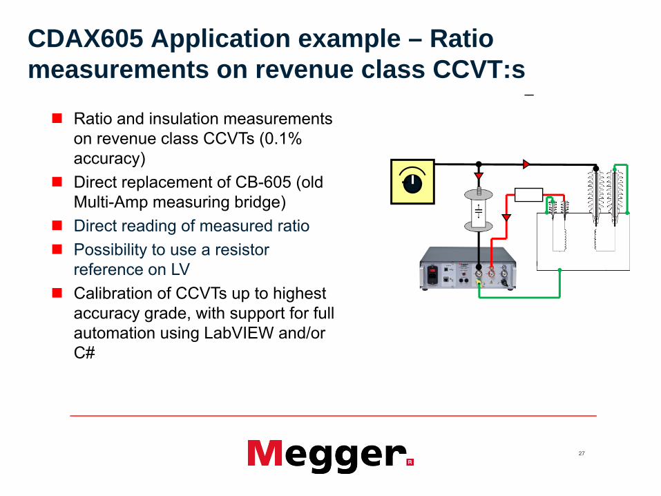
CDAX605 Application example – Ratio measurements on revenue class CCVT:s
Ratio and insulation measurements on revenue class CCVTs (0.1% accuracy)Direct replacement of CB-605 (old Multi-Amp measuring bridge)Direct reading of measured ratioPossibility to use a resistor reference on LVCalibration of CCVTs up to highest accuracy grade, with support for full automation using LabVIEW and/or C#
-

28
CDAX605 – Demo boxEasy to demonstrateBoth capacitance and ratioAdjustable ”output voltage”

29
CRD605 – HV resistor
20 MΩMax 2 kV (100 µA)To be used for ratio measurementsOr in any other application requesting a stable high-voltage resistor…

30