Power Tower - Scene7
26
2866.1‐102916 MPORTANT: Read all instructions carefully before using this product. Retain this owner’s manual for future reference. The specifications of this product may vary from this photo and, subject to change without notice. Power Tower
Transcript of Power Tower - Scene7

2866.1‐102916
MPORTANT: Read all instructions carefully before using this product.
Retain this owner’s manual for future reference. The specifications of this
product may vary from this photo and, subject to change without notice.
Power Tower

PLEASE DO NOT RETURN THIS PRODUCT TO THE STORE.
If you need help with product information, assembly, or replacement parts. Please contact customer service.
Email us at:
Or call us at: 1-844-641-7920
Hours: 8:00 am to 5:00 pm (PST) Daily
STOPARRÊTALTO
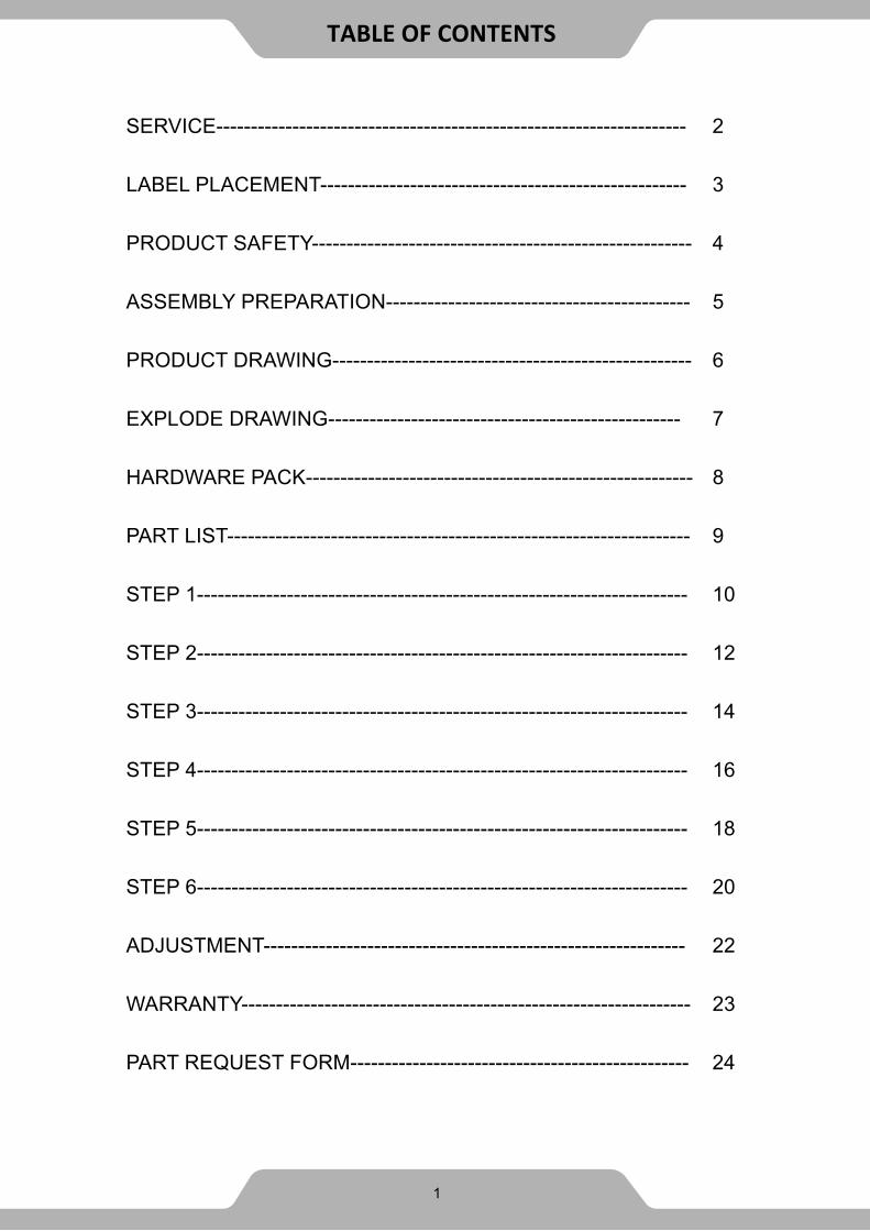
SERVICE-------------------------------------------------------------------- 2
LABEL PLACEMENT----------------------------------------------------- 3
PRODUCT SAFETY------------------------------------------------------- 4
ASSEMBLY PREPARATION-------------------------------------------- 5
PRODUCT DRAWING---------------------------------------------------- 6
EXPLODE DRAWING--------------------------------------------------- 7
HARDWARE PACK-------------------------------------------------------- 8
PART LIST------------------------------------------------------------------- 9
STEP 1----------------------------------------------------------------------- 10
STEP 2----------------------------------------------------------------------- 12
STEP 3----------------------------------------------------------------------- 14
STEP 4----------------------------------------------------------------------- 16
STEP 5----------------------------------------------------------------------- 18
STEP 6----------------------------------------------------------------------- 20
ADJUSTMENT------------------------------------------------------------- 22
WARRANTY----------------------------------------------------------------- 23
PART REQUEST FORM------------------------------------------------- 24
TABLE OF CONTENTS
1

IMPORTANT: FOR NORTH AMERICA ONLY
For damage or defective product, questions, replacement parts or any other
service support, please contact our customer service department (8:00 AM - 5:00
PM Pacific Standard Time, Open Daily) by below methods:
For Best Service Email:
Website: www.paradigmhw.com
Toll-Free: 1-844-641-7920
Please have the following information ready when requesting for service:
Your name
Phone number
Model number
Serial number
Part number
Proof of Purchase
For damaged or defective product please contact our customer service
before returning to the store.
* Emailing us with the information above will be the best method to
receive a response during peak business hours. **Response time may vary.
Paradigm Health & Wellness, Inc.
1189 Jellick Ave.
City of Industry, CA 91748, USA
SERVICE
2

UN
DER
PEN
ALT
Y O
F LA
W T
HIS
TAG
N
OT
TO B
E RE
MO
VED
EXC
EPT
BY T
HE
CON
SUM
ERN
OTI
CE
This
art
icle
doe
s no
t mee
t
requ
irem
ents
of C
alifo
rnia
Bu
reau
of H
ome
Furn
ish-
ings
tech
nica
l bul
letin
117
. Ca
re s
houl
d be
exe
rcis
ed
burn
ing
ciga
rett
s.
ALL
NEW
MA
TERI
ALC
ON
SIST
ING
O
F PO
LYUR
ETHA
NE
FOA
M P
AD
_100
%
REG
ISTR
Y N
O. V
A25
302
(CN)
man
ufac
ture
r tha
t the
mat
eria
ls
in th
is a
rtic
le a
re d
escr
ibed
in
acco
rdan
ce w
ith la
w.
Para
digm
Hea
lth a
nd W
elln
ess,
Inc.
1189
Jelli
ck A
ve. C
ity o
f Ind
ustr
yCA
917
48, U
SA
Para
digm
Hea
lth a
nd W
elln
ess,
Inc.
1189
Jelli
ck A
ve. C
ity o
f Ind
ustr
y, C
A
9174
8 U
SA
SE S
AN
CIO
NA
RÁ L
EGA
LMEN
TE A
Q
UIE
NES
QU
ITEN
EST
A E
TIQ
UET
A.
SOLO
EL
CON
SUM
IDO
R PO
DRÁ
Q
UIT
ARL
A.
MAT
ERIA
L CO
MPL
ETA
MEN
TE N
UEV
O
COM
PUES
TO D
E 10
0% R
ELLE
NO
DE
ESPU
MA
DE
POLI
URE
TAN
O.
NO
TIFI
CA
CIÓ
NEs
te a
rtíc
ulo
no s
e aj
usta
a
Mob
iliar
io b
olet
ín té
cnic
o 11
7. C
uida
do d
e Ca
lifor
nia
debe
n ej
erce
rse
cerc
a de
un
a lla
ma
abie
rta
o co
n ci
gare
tts
ardi
ente
s.
NO
. DE
REG
VA
2530
2 (C
N)
mat
eria
les
de e
ste
artíc
ulo
se
desc
riben
seg
ún la
s le
yes.
Para
digm
Hea
lth a
nd W
elln
ess,
Inc.
1189
Jelli
ck A
ve. C
ity o
f Ind
ustr
yCA
917
48, U
SA
SOU
S PE
INE
DE
SAN
CTI
ON
LÉG
ALE
, CE
TTE
ÉTIQ
UET
TE N
E PE
UT
ÊTRE
EN
LEVÉ
E PA
R U
NE
PERS
ON
NE
AUTR
E Q
UE
LE C
ON
SOM
MAT
EUR
AVIS
Ce p
rodu
it ne
sat
isfa
it pa
s -
du d
evis
tech
niqu
e du
Ca
lifor
nia
Bure
au o
f Hom
e Fu
rnis
hing
s. N
e pa
s ut
ilise
r pr
ès d
’une
sou
rce
de
nue
(cig
aret
tes,
etc.
)
ENTI
ÈREM
ENT
FABR
IQUÉ
DE
MA
TÉRI
AUX
NEU
FS R
EMBO
URRA
GE
DE
MO
USSE
DE
POLY
URÉT
HAN
E 10
0 %
NO
D’E
NRE
GIS
TREM
ENT
VA25
302
(CN)
Cett
e ét
ique
tte
est a
ppos
ée
conf
orm
émen
t aux
lois
Can
a-di
enne
s.
LABEL PLACEMENT
3
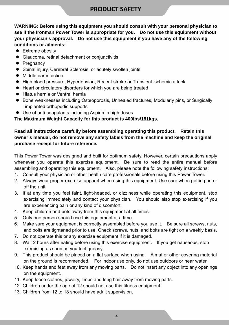
WARNING: Before using this equipment you should consult with your personal physician to see if the Ironman Power Tower is appropriate for you. Do not use this equipment without your physician’s approval. Do not use this equipment if you have any of the following conditions or ailments: Extreme obesity Glaucoma, retinal detachment or conjunctivitis Pregnancy Spinal injury, Cerebral Sclerosis, or acutely swollen joints Middle ear infection High blood pressure, Hypertension, Recent stroke or Transient ischemic attack Heart or circulatory disorders for which you are being treated Hiatus hernia or Ventral hernia Bone weaknesses including Osteoporosis, Unhealed fractures, Modularly pins, or Surgically
implanted orthopedic supports Use of anti-coagulants including Aspirin in high doses
The Maximum Weight Capacity for this product is 400lbs/181kgs. Read all instructions carefully before assembling operating this product. Retain this owner’s manual, do not remove any safety labels from the machine and keep the original purchase receipt for future reference. This Power Tower was designed and built for optimum safety. However, certain precautions apply whenever you operate this exercise equipment. Be sure to read the entire manual before assembling and operating this equipment. Also, please note the following safety instructions: 1. Consult your physician or other health care professionals before using this Power Tower. 2. Always wear proper exercise apparel when using this equipment. Use care when getting on or
off the unit. 3. If at any time you feel faint, light-headed, or dizziness while operating this equipment, stop
exercising immediately and contact your physician. You should also stop exercising if you are experiencing pain or any kind of discomfort.
4. Keep children and pets away from this equipment at all times. 5. Only one person should use this equipment at a time. 6. Make sure your equipment is correctly assembled before you use it. Be sure all screws, nuts,
and bolts are tightened prior to use. Check screws, nuts, and bolts are tight on a weekly basis. 7. Do not operate this or any exercise equipment if it is damaged. 8. Wait 2 hours after eating before using this exercise equipment. If you get nauseous, stop
exercising as soon as you feel queasy. 9. This product should be placed on a flat surface when using. A mat or other covering material
on the ground is recommended. For indoor use only, do not use outdoors or near water. 10. Keep hands and feet away from any moving parts. Do not insert any object into any openings
on the equipment. 11. Keep loose clothes, jewelry, limbs and long hair away from moving parts. 12. Children under the age of 12 should not use this fitness equipment. 13. Children from 12 to 18 should have adult supervision.
4
PRODUCT SAFETY

Warning: It is highly recommend that you have assistance during the assembly of the IRONMAN
strength equipment.
1. Tools for assembly:
General tools you may needed for the assembly of the IRONMAN strength equipment.
Metric Allen Key Set
Metric Wrench Set and Adjustable Wrench
Flat Screwdrivers
Phillips Screwdrivers
Rubber Mallet
Silicone Spray Oil
2. Insert bolts into the frame as illustrated in the drawing of each of the steps.
3. Hand-tighten the bolts, nuts, and screw during assembly. Hand-tightening will allow for easily
aligning the parts during assembly. Tighten all the hardware once the entire unit has been
completely assembled.
4. It is highly recommended that a professional installer assembles the IRONMAN strength
equipment. But, with the proper assistance, the right tools, and strictly following the assembly
steps, and given enough time; the assembly of the unit can be achieved without professional
help.
5. Thoroughly read each step before proceeding to assemble the items of that step.
6. To aid in assembly of the equipment, the hardware pack (bolts, nuts, washer…etc.) have been
presorted according to their corresponding steps. See Hardware Pack page.
7. When the equipment is fully assembled check all the functions for correct operation. Consult the
manual if you experience any issues, or for further help please contact our service department.
See page 2.
ASSEMBLY PREPARATION
5

6
PRODUCT DRAWING

EXPLODE DRAWING
7

HARDWARE PACK
8

Part# Description Q’ty. Part# Description Q’ty.
A Base Beam 2 52 Washer D13.5xD24x2.5 52
B Lower Post 2 56 Washer D16xD8.4x1.6 7
C Upper Crossbeam 1 57 Spring Washer
D12.3xD8.1x2.1 7
D Lower Crossbeam 1 58 Spring Washer
D15.4xD10.2x2.6 2
E Adjustable Handlebar 2 76 Nylon Nut M12 26
F Wide Grip Pull Up Bar 2 103 Locking Pin Φ8x10⁷ 2
G Close Grip Pull Up Bar 2 120 Big End Cap Φ70*Φ21*38 2
H Grip Post 2 131 Domed End Cap Φ32xt2.0 8
I-R Right Dip Bar 1 132 Domed End Cap Φ50xt2.0 2
I-L Left Dip Bar 1 133 Round Cap Φ25xt2.0 2
J Upper Post 2 158 Rectangular End
Cap 75x50x2 2
K Mounting Plate
150*50*T5.0 2 190 Footpad 90x65x5 2
L Mounting Plate
100*40*T6.0 2 191 Footpad 145x65x5 2
M Backrest 1 204 Handgrip Φ49xΦ55x250 2
P Forearm Pad 2 205 Handgrip
Φ24xΦ32x200 2
3 Hex Bolt M8x1.25x25L 1 206 Handgrip
Φ31xΦ38x310 2
7 Hex Bolt M12x1.75x80L 20 207 Handgrip
Φ31xΦ38x115 2
17 Hex Bolt M12x1.75x85L 6 208 Handgrip Φ31xΦ38x300 4
18 Hex Bolt M10x1.5x25L 2 222 Foam
Roller Φ100*Φ25*200 2
19 Hex Bolt
M8x1.25x70L 6 223
Foam Roller Sleeve
Φ100**Φ200*t1.0 2
51 Washer D20xD10.5x2.0 2
PART LIST
9

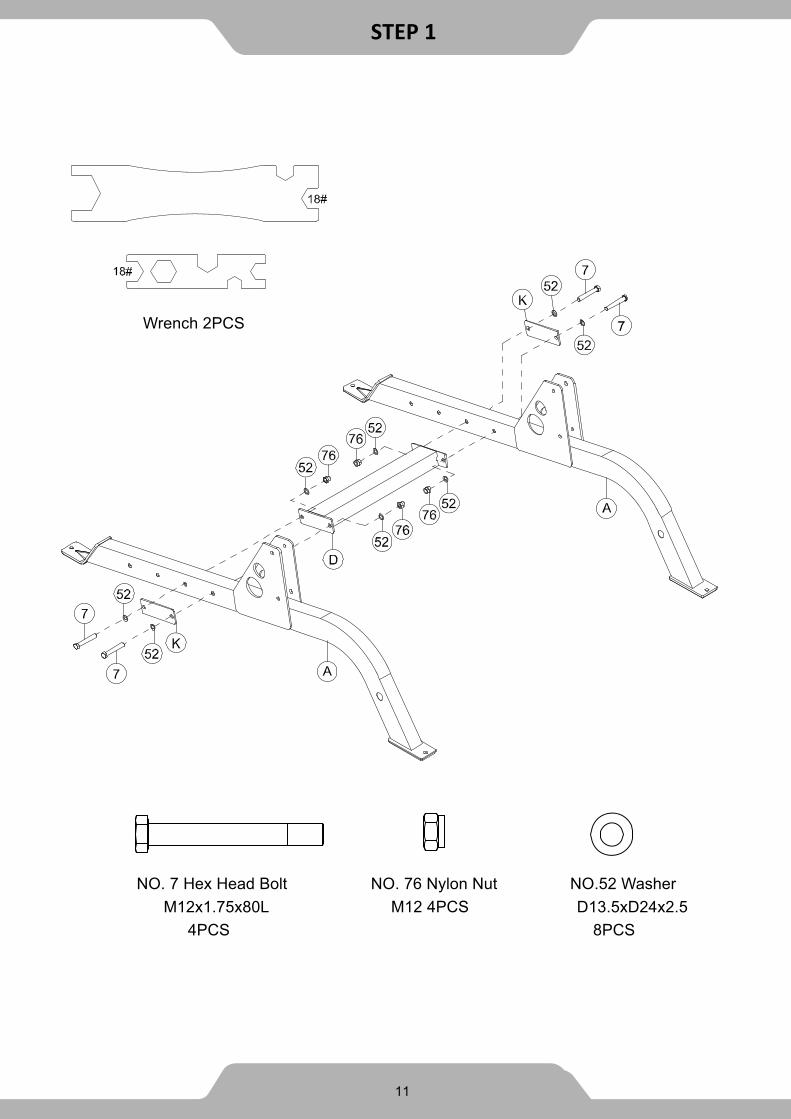
Appearance upon completion of Step 1.
1A. Attach the Lower Crossbeam (D) between the two Base Beams (A) and
two Mounting Plates (K) by using:
8 - (52) Washer D13.5xD24x2.5
4 - (7) Hex Bolt M12x1.75x80L
4 - (76) Nylon Nut M12
Thoroughly tighten the hardware once complete.
Tip: Install the Base Beams (A) with the Ironman logo facing outward.
Tip: The Lower Crossbeam (D) can be mounted in three different positions.
There are additional holes towards the rear of the holes which this step
instructs for assembly. If the Lower Crossbeam (D) is interfering with your
workout in the position this step recommends, try mounting the Lower
Crossbeam (D) to one of the other two positions. The Lower Crossbeam
must be installed in one of the available configurations.
Tip: The Base Beams (A) have holes at the front and rear for bolting the unit to the floor.
STEP 1
10
8
STEP 1
11
NO. 7 Hex Head Bolt
M12x1.75x80L
4PCS
NO. 76 Nylon Nut
M12 4PCS
NO.52 Washer
D13.5xD24x2.5
8PCS
Wrench 2PCS

Appearance upon completion of Step 2.
2A. Attach both Lower Posts (B) to the two Base Beams (A) by using:
8 - (52) Washer D13.5xD24x2.5
4 - (7) Hex Bolt M12x1.75x80L
4 - (76) Nylon Nut M12 Thoroughly tighten the hardware once complete.
STEP 2
12

STEP 2
13
NO. 7 Hex Head Bolt
M12x1.75x80L
4PCS
NO. 76 Nylon Nut
M12 4PCS
NO.52 Washer
D13.5xD24x2.5
8PCS
Wrench 2PCS

Appearance upon completion of Step 3.
3A. Insert one Upper Post (J) into the bracket of the Lower Post (B). Continue holding the Upper Post (J) and align its holes with the holes of the Lower Post (B). Insert three Hex Bolts (17) all the way through the Lower Post (B) and Upper Post (J). Mount Upper Crossbeam (C) by inserting the threaded ends of the two Hex Bolts (17) sticking out of Lower Posts (B) and Upper Post (J). Attach all three parts by using:
6 - (52) Washer D13.5xD24x2.5
3 - (76) Nylon Nut M12
3 - (17) Hex Bolt M12x1.75x85L
Tip: Keep the rectangular tab on the Upper Crossbeam (C) facing
forward.
3B. Insert the second Upper Post (J) into the bracket of the other Lower Post (B). Continue holding the Upper Post (J) and align its holes with the holes of the Lower Post (B). Insert three Hex Bolts (17) all the way through the Lower Post (B), the Upper Post (J) and the Upper Crossbeam (C). Attach all three parts by using:
6 - (52) Washer D13.5xD24x2.5
3 - (76) Nylon Nut M12
3 - (17) Hex Bolt M12x1.75x85L
Thoroughly tighten the hardware once complete.
STEP 3
14

STEP 3
15
NO. 17 Hex Head Bolt
M12x1.75x85L
6PCS
NO. 76 Nylon Nut
M12 6PCS
NO.52 Washer
D13.5xD24x2.5
12PCS
Wrench 2PCS

Appearance upon completion of Step 4.
4A. Attach the Forearm Pad (P) to the RIGHT Dip Bar (I-R) as in image AA-2,
using:
2 - (56) Washer D16xD8.4x1.6
2 - (57) Spring Washer D12.3xD8.1x2.1
2 - (19) Hex Bolt M8x1.25x70L
Thoroughly tighten the hardware once complete.
4B. Attach the RIGHT Dip Bar (I-R) to the RIGHT Lower Post (B) by using:
4 - (52) Washer D13.5xD24x2.5
2 - (76) Nylon Nut M12
2 - (7) Hex Bolt M12x1.75x80L
4C. Attach a Grip Post (H) to the RIGHT Dip Bar (I-R) by using:
1 - (51) Washer D20xD10.5xT2.0
1 - (58) Spring Washer D15.4xD10.2x2.6
1 - (18) Hex Bolt M10x1.5x25L
Thoroughly tighten the hardware once complete.
4D. Repeat these steps for assembling the LEFT Dip Post (I-L).
Tip: The right Dip Bar (I-R) is marked with an R sticker. The left Dip Bar (I-L)
is marked with and L sticker
16
STEP 4

STEP 4
17
NO. 7 Hex Head Bolt M12x1.75x80L
4PCS
NO. 76 Nylon Nut M12
4PCS
NO.52 WasherD13.5xD24x2.5
8PCS
NO. 57 Spring Washer D12.3xD8.1x2.1
4PCS
NO.19 Hex Bolt M8x1.25x70L
4PCS
NO.56 WasherD16xD8.4x1.6
4PCS
NO.18 Hex Bolt M10x1.5x25L
2PCS
NO.58 Spring Washer D15.4xD10.2x2.6
2PCS
NO.51 WasherD20xD10.5x2
2PCS
Wrench 2PCS

Appearance upon completion of Step 5.
5. Attach the Backrest (M) to the Upper Crossbeam (C) at the by first
aligning the screw holes and hand tightening the hardware listed below into
place. Once all hardware has been inserted, fasten the hardware tightly.
2 - (19) Hex Bolt M8x1.25x70L
1 - (3) Hex Bolt M8x1.25x25L
3 - (57) Spring Washer D12.3xD8.1x2.1
3 - (56) Washer D16xD8.4x1.6
Thoroughly tighten the hardware once complete.
STEP 5
18

STEP 5
NO.56 Washer
D16xD8.4x1.6
3PCS
NO.19 Hex Bolt
M8x1.25x70L
2PCS
NO.57 Spring Washer
D12.3xD8.1x2.1
3PCS
NO.3 Hex Bolt
M8x1.25x25L
1PC
19
Wrench 1PC

Appearance upon completion of Step 6.
6A. Insert both Wide Grip Pull Up Bars (F) into the slots at the top of the
Upper Posts (J) and attach by using:
4 - (7) Hex Bolt M12x1.75x80L
8 - (52) Washer D13.5xD24x2.5
4 - (76) Nylon Nut M12
6B. Attach the Close Grip Pull Up Bars (G) and Mounting Plates (L) to Upper
Posts (J) by using:
4 - (7) Hex Bolt M12x1.75x80L
8 - (52) Washer D13.5xD24 x2.5
4 - (76) Nylon Nut M12
Thoroughly tighten the hardware once complete.
6C. Insert the Adjustable Handlebars (E) into the lowest set of holes marked
and , secure them into place by using:
2 - (103) Locking Pin Φ8*10
STEP 6
20

STEP 6
21
NO. 7 Hex Head Bolt
M12x1.75x80L
8PCS
NO. 76 Nylon Nut
M12x1.75x12T
8PCS
NO.52 Washer
D13.5xD24x2.5
16PCS
NO. 103 Locking Pin
Φ8x10⁷ 2 PCS
Wrench 2PCS
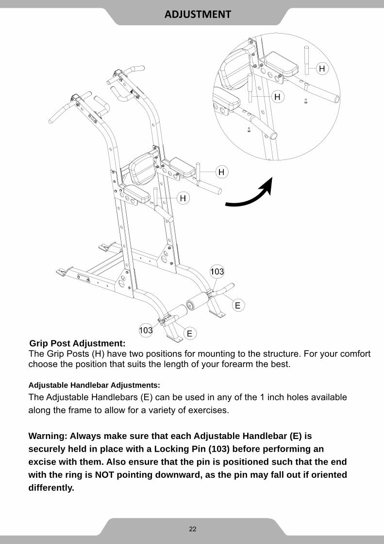
Grip Post Adjustment: The Grip Posts (H) have two positions for mounting to the structure. For your comfort choose the position that suits the length of your forearm the best. Adjustable Handlebar Adjustments:
The Adjustable Handlebars (E) can be used in any of the 1 inch holes available
along the frame to allow for a variety of exercises.
Warning: Always make sure that each Adjustable Handlebar (E) is
securely held in place with a Locking Pin (103) before performing an
excise with them. Also ensure that the pin is positioned such that the end
with the ring is NOT pointing downward, as the pin may fall out if oriented
differently.
ADJUSTMENT
23 22

MANUFACTURER’S LIMITED WARRANTY Paradigm Health & Wellness guarantees to the original purchaser that this product is free from defects in material and workmanship when used for the purpose intended, under the conditions that it has been installed and operated in accordance with Paradigm’s Owner’s Manual. Paradigm’s obligation under this warranty applies to the following:
COMPONENT LENGTH OF WARRANTY All Components Limited Lifetime Guarantee for home use only
Exclusions from Warranty Coverage:
Paradigm does not warrant against and is not responsible for, and no implied warranty shall be
deemed to cover, any product failure, product malfunction, or damages attributable to:
1. Improper installation and/or failure to abide by Paradigm’s installation guidelines;
2. Use of this product beyond normal home use, or in an application for which it was not designed.
3. All exchanged parts and Products replaced under this limited warranty will become the property
of Paradigm Health and Wellness.
4. Damage caused by vandalism, accidents, inadequate maintenance, or by animals.
5. Any act of Nature (such as fire, flooding, snow, ice, hurricane, earthquake, lightning or other
natural disaster), environmental condition (such as air pollution, mold, mildew, etc.), or staining
from foreign substances (such as dirt, grease, oil, etc.).
6. Normal weathering due to exposure to sunlight, weather and atmosphere which can cause
colored surfaces to, among other things, flake, rust, accumulate dirt or stains.
7. Improper operation, alteration, handling, storage, abuse or neglect of the product.
Paradigm, using its sole discretion, will either repair or replace free of charge any part(s)
proven to be defective under normal home use. Any repair or replacement shall provide
no new warranty coverage, but shall retain only the remaining portion of the original
product’s warranty. This warranty is offered only to the original purchaser and is not
transferable. Proof of original purchase is required.
Ordering Replacement Parts
Replacement parts can be ordered by emailing our customer service department:
Open Daily 8:00 AM - 5:00 PM (PST).
When ordering replacement parts please have the following information ready:
1. Owner’s Manual
2. Model Number
3. Description of Parts
4. Part Number
5. Date of Purchase
23
WARRANTY

Paradigm Health & Wellness, Inc. EMAIL THIS FORM WITH YOUR RECIEPT OF PURCHASE TO
NAME: _______________________________________________________
ADDRESS: ____________________________________________________
CITY ______________ STATE ______________ ZIP ___________________
TELEPHONE: (Day) ____________________________________________
(Night) ____________________________________________
SERIAL#: _____________________________________________________
MODEL#: _____________________________________________________
PURCHASE DATE: _____________________________________________
PLACE OF PURCHASE: _________________________________________
“YOUR ORDER WILL BE PROCESSED WITHIN 3 BUSINESS DAYS”
* This form can also be faxed in Fax #: 626-810-2166
PART # DESCRIPTION QTY
PART REQUEST FORM
24