POWER SYSTEM -II LAB (EE-328-F) VI SEMESTER...
24
POWER SYSTEM-II LAB (EE-328-F) DEPARTMENT OF ELECTRICAL AND ELECTRONICS ENGINEERING DRONACHARY COLLEGE OF ENGINEERING Page 1 POWER SYSTEM -II LAB (EE-328-F) VI SEMESTER Electrical and Electronics Engineering DEPARTMENT OF ELECTRICAL & ELECTRONICS DRONACHARAY COLLEGE OF ENGINEERING KHENTAWAS, GURGAON-123506
Transcript of POWER SYSTEM -II LAB (EE-328-F) VI SEMESTER...
POWER SYSTEM-II LAB (EE-328-F)
DEPARTMENT OF ELECTRICAL AND ELECTRONICS ENGINEERING DRONACHARY COLLEGE OF ENGINEERING Page 1
POWER SYSTEM -II LAB
(EE-328-F)
VI SEMESTER
Electrical and Electronics Engineering
DEPARTMENT OF ELECTRICAL & ELECTRONICS DRONACHARAY COLLEGE OF ENGINEERING
KHENTAWAS, GURGAON-123506

POWER SYSTEM-II LAB (EE-328-F)
DEPARTMENT OF ELECTRICAL AND ELECTRONICS ENGINEERING DRONACHARY COLLEGE OF ENGINEERING Page 2
LIST OF EXPERIMENTS
S.NO NAME OF THE EXPERIMENT PAGE NO.
1. To study the performance of under voltage relay. 3
2. To study performance characteristics of typical DC distribution system in radial configuration..
4
3. To study performance characteristics of typical DC distribution system in ring main configuration...
7
4. Testing of breakdown strength of a transformer oil. 10
5. To study characteristics of MCB & HRC Fuse.
12
6. To study the performance of a over voltage relay. 14
7. Determine the ABCD,H, Z and Image parameters of Short Transmission Line 15
8. Determine the ABCD,H,Z and Image parameters of Medium Transmission Line 18
9. Determine the ABCD,H,Z and Image parameters of Long Transmission Line 21
10. To study flash point test of transformer oil. 24
POWER SYSTEM-II LAB (EE-328-F)
DEPARTMENT OF ELECTRICAL AND ELECTRONICS ENGINEERING DRONACHARY COLLEGE OF ENGINEERING Page 3
Experiment No-1
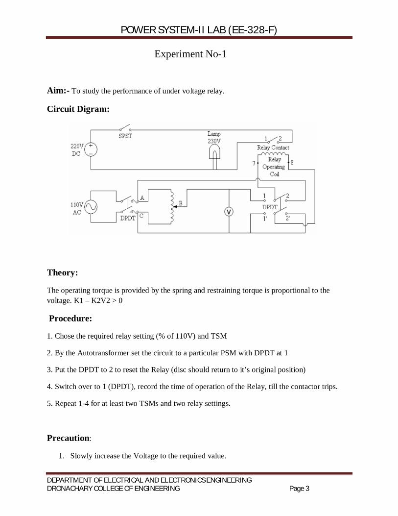
Aim:- To study the performance of under voltage relay.
Circuit Digram:
Theory:
The operating torque is provided by the spring and restraining torque is proportional to the voltage. K1 – K2V2 > 0
Procedure:
1. Chose the required relay setting (% of 110V) and TSM
2. By the Autotransformer set the circuit to a particular PSM with DPDT at 1
3. Put the DPDT to 2 to reset the Relay (disc should return to it’s original position)
4. Switch over to 1 (DPDT), record the time of operation of the Relay, till the contactor trips.
5. Repeat 1-4 for at least two TSMs and two relay settings.
Precaution:
1. Slowly increase the Voltage to the required value.

POWER SYSTEM-II LAB (EE-328-F)
DEPARTMENT OF ELECTRICAL AND ELECTRONICS ENGINEERING DRONACHARY COLLEGE OF ENGINEERING Page 4
Experiment No-2
Aim:- To study performance characteristics of typical DC distribution system in radial.
Apparatus Required:-
Main Cord Patch Cords 40W bulbs(5)
Theory
Whole of the power system can be subdivided in to number of radial feeders fed from one end. Generally such radial feeders are protected by over current and earth fault relays used as primary relays for 11 kV and 66 kV lines. For lines of voltage rating beyond 66 kV, distance protection is applied as a primary protection whereas over current and earth fault relays are used as back up relays. A simplified radial feeder network without transformers (in actual practice transformers do exist at substations) is shown in single line diagram of fig. 1.1 below.
If the fault occurs in distribution network, fuse should isolate the faulty section. Should the fuse fail, relay R3 shall give back-up protection. Relays R1, R2, and R3 act as primary relays for faults in section I, section I, and section III respectively. If fault in section III is not cleared by relaying scheme at relaying point R3, relay R2 will act as a back-up. Similarly back-up protection is provided by relay R1 for faults in section II. A,B, C and D are substations in fig. 1.1.

POWER SYSTEM-II LAB (EE-328-F)
DEPARTMENT OF ELECTRICAL AND ELECTRONICS ENGINEERING DRONACHARY COLLEGE OF ENGINEERING Page 5
Procedure
1.Frist of all make sure that the earthing of your laboratory is proper and connected to the terminal provided on back side of the panel.
2. Make sure that the variac knob is at zero position.
3.Make the connection according to Diagram.
4.Now insert 40W bulbs into bulb holders.
5. Now switch ON the AC mains and MCB of your trainer.
6. Now vary the knob of variac up to 220V.
7. Switch ON all the toggle switches S1,S2,S3,S4 and S5.(Upward direction).
8. You will observe all the bulbs in Radial Distribution section will glow. That means all the connections are right.
9. Now put the variac knob at zero position.
10. Connect voltmeter terminal V4 to –(ve) terminal of Consumer4.
11. Now insert one end of patch cord to V3 terminal & second end will connect to measured terminals.
12.Once again vary the knob of variac up to 220V.
13. Now observe the voltage drop in each Consumer terminal and note the readings.
14. Put the variac knob at zero postion.
15. Switch Off the mains and remove all the connection and bulbs.
Observation Table:
V1 V2 I1 Consumer1
Consumer2
Consumer3
Consumer4
Consumer5

POWER SYSTEM-II LAB (EE-328-F)
DEPARTMENT OF ELECTRICAL AND ELECTRONICS ENGINEERING DRONACHARY COLLEGE OF ENGINEERING Page 6
Where,
V1 is the Source Voltage
V2 is Consumers Voltage
I1 is Source Current
Result:
If the distributor is connected to the supply system on one end only then the end of the feeder nearest to the generating station would be heavily loaded and the Consumers at the distance end of the distributor would be subjected to large voltage variations as the load varies.

POWER SYSTEM-II LAB (EE-328-F)
DEPARTMENT OF ELECTRICAL AND ELECTRONICS ENGINEERING DRONACHARY COLLEGE OF ENGINEERING Page 7
Experiment No.-3
Aim:- To study performance characteristics of typical DC distribution system in ring.
Apparatus Required:-
Main Cord Patch Cords 40W bulbs(5)
Theory:- one ring network of distributors is fed by more than one feeder. In this case if one feeder is under fault or maintenance, the ring distributor is still energized by other feeders connected to it. In this way the supply to the consumers is not affected even when any feeder becomes out of service. In addition to that the ring main system is also provided with different section isolates at different suitable points. If any fault occurs on any section, of the ring, this section can easily be isolated by opening the associated section isolators on both sides of the faulty zone.

POWER SYSTEM-II LAB (EE-328-F)
DEPARTMENT OF ELECTRICAL AND ELECTRONICS ENGINEERING DRONACHARY COLLEGE OF ENGINEERING Page 8
Ring Mains Distribution System
Procedure
1.Frist of all make sure that the earthing of your laboratory is proper and connected to the terminal provided on back side of the panel.
2. Make sure that the variac knob is at zero position.
3.Make the connection according to Diagram.
4.Now insert 40W bulbs into bulb holders.
5. Now switch ON the AC mains and MCB of your trainer.
6. Now vary the knob of variac up to 220V.
7. Switch ON all the toggle switches S1,S2,S3,S4 and S5.(Upward direction).
8. You will observe all the bulbs in Radial Distribution section will glow. That means all the connections are right.
9. Now put the variac knob at zero position.
10. Connect voltmeter terminal V6 to –(ve) terminal of source1.
POWER SYSTEM-II LAB (EE-328-F)
DEPARTMENT OF ELECTRICAL AND ELECTRONICS ENGINEERING DRONACHARY COLLEGE OF ENGINEERING Page 9
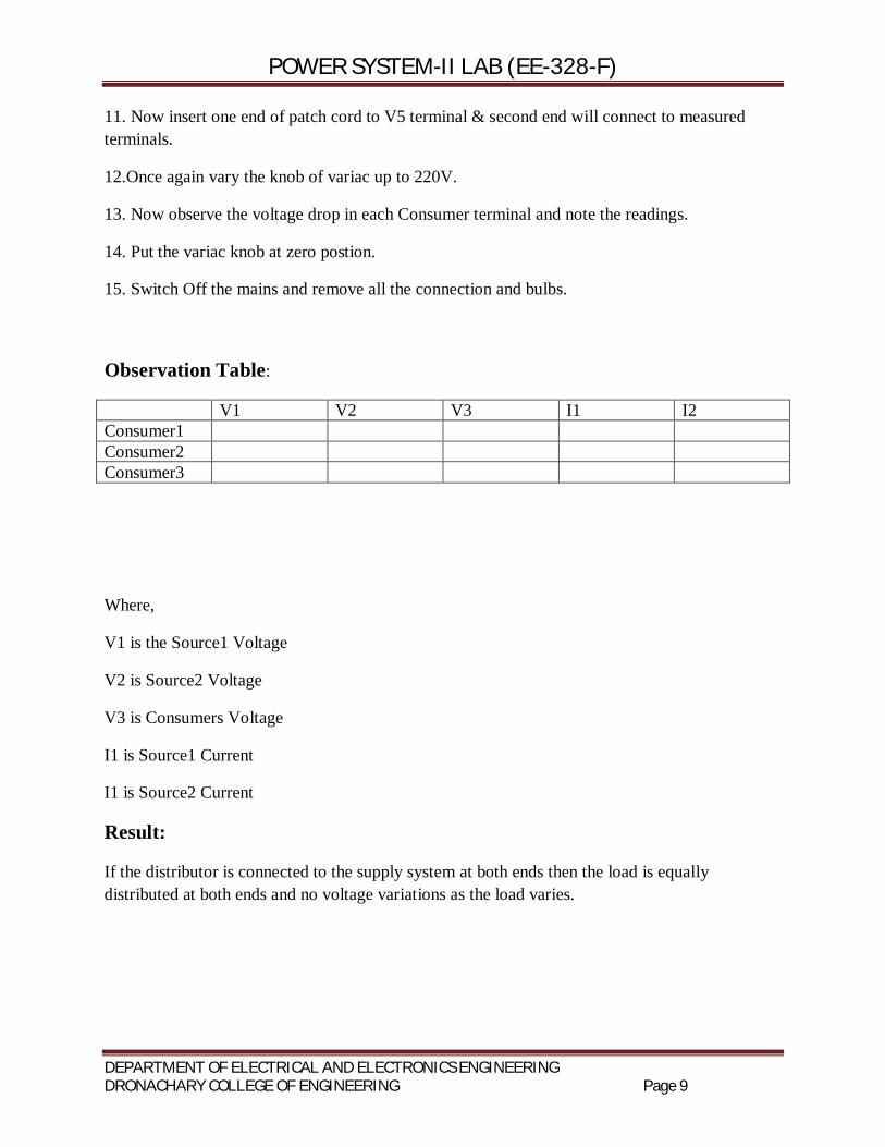
11. Now insert one end of patch cord to V5 terminal & second end will connect to measured terminals.
12.Once again vary the knob of variac up to 220V.
13. Now observe the voltage drop in each Consumer terminal and note the readings.
14. Put the variac knob at zero postion.
15. Switch Off the mains and remove all the connection and bulbs.
Observation Table:
V1 V2 V3 I1 I2 Consumer1 Consumer2 Consumer3
Where,
V1 is the Source1 Voltage
V2 is Source2 Voltage
V3 is Consumers Voltage
I1 is Source1 Current
I1 is Source2 Current
Result:
If the distributor is connected to the supply system at both ends then the load is equally distributed at both ends and no voltage variations as the load varies.

POWER SYSTEM-II LAB (EE-328-F)
DEPARTMENT OF ELECTRICAL AND ELECTRONICS ENGINEERING DRONACHARY COLLEGE OF ENGINEERING Page 10
Experiment No-4
Objective: Testing of breakdown strength of a transformer oil.
Apparatus Required: Transformer oil test kit, Transformer oil.
Theory:
The insulation oil of voltage- and current-transformers fulfills the purpose of insulating as well as cooling. Thus, the dielectric quality of transformer oil is a matter of secure operation of a transformer.
As transformer oil deteriorates through aging and moisture ingress, transformer oil should, depending on economics, transformer duty and other factors, be tested periodically.
Procedure: 1. Make sure that the mains switch of control panel is off position.
2. Now take out the acrylic oil cup from the setup.
3. Adjust the gap in between both electrodes in the oil cup with the help of “GO” and “NOGO” gauge provided
4. Fill the transformer oil in the acrylic oil cup up to top level and keep the oil cup on the aluminum studs carefully placed on output insulators.
5. Let the oil settle for half minute.
6. Cover the oil cup & closed acrylic top door of the control panel properly.
7. Connect the main cord to the mains socket(230V).
8. Switch ON mains supply as well as mains switch provide in front panel of control setup.
9. After switch on the panel ,green neon lamp will glow.it indicate that input supply appears at the control setup but high voltage is off.
10. If green lamp does not glow ,then check whether acrylic door is properly closed or not.
11. Now turn the toggle switch at ‘Raise’ position.
12. After that turn on the HV On switch on the panel then Red neon lamp will glow. It indicates that high voltage is being generated at the secondary winding of the transformer that is high voltage is present between the electrodes in the oil cup.
13. At some point of voltage , the insulation of the test oil get breakdown and a spark is seen in between the electrodes instantaneously.
POWER SYSTEM-II LAB (EE-328-F)
DEPARTMENT OF ELECTRICAL AND ELECTRONICS ENGINEERING DRONACHARY COLLEGE OF ENGINEERING Page 11
14. Record the reading of voltmeter into observation table.
15. Repeat the above steps and take no. of readings in fixed time interval.
16. Switch off the main supply.

POWER SYSTEM-II LAB (EE-328-F)
DEPARTMENT OF ELECTRICAL AND ELECTRONICS ENGINEERING DRONACHARY COLLEGE OF ENGINEERING Page 12
Experiment No-5
Aim: To study characteristics of MCB & HRC Fuse.
Apparatus Required:-
Rheostat 220 ohm.2.8 A
Connecting leads
Procedure:-
1. Make sure that the switch S1 is off means the circuit is open. 2. Make the connection according to the diagram. 3. Put the B type MCB knob upwards. 4. Switch On the mains, LCD switch S2 and S1 switch. 5. With the help of variac and rheostat adjust the current say 9A. 6. After adjusting the current switch off S1. 7. Now again on the switch S1 and measure the current reading.
POWER SYSTEM-II LAB (EE-328-F)
DEPARTMENT OF ELECTRICAL AND ELECTRONICS ENGINEERING DRONACHARY COLLEGE OF ENGINEERING Page 13
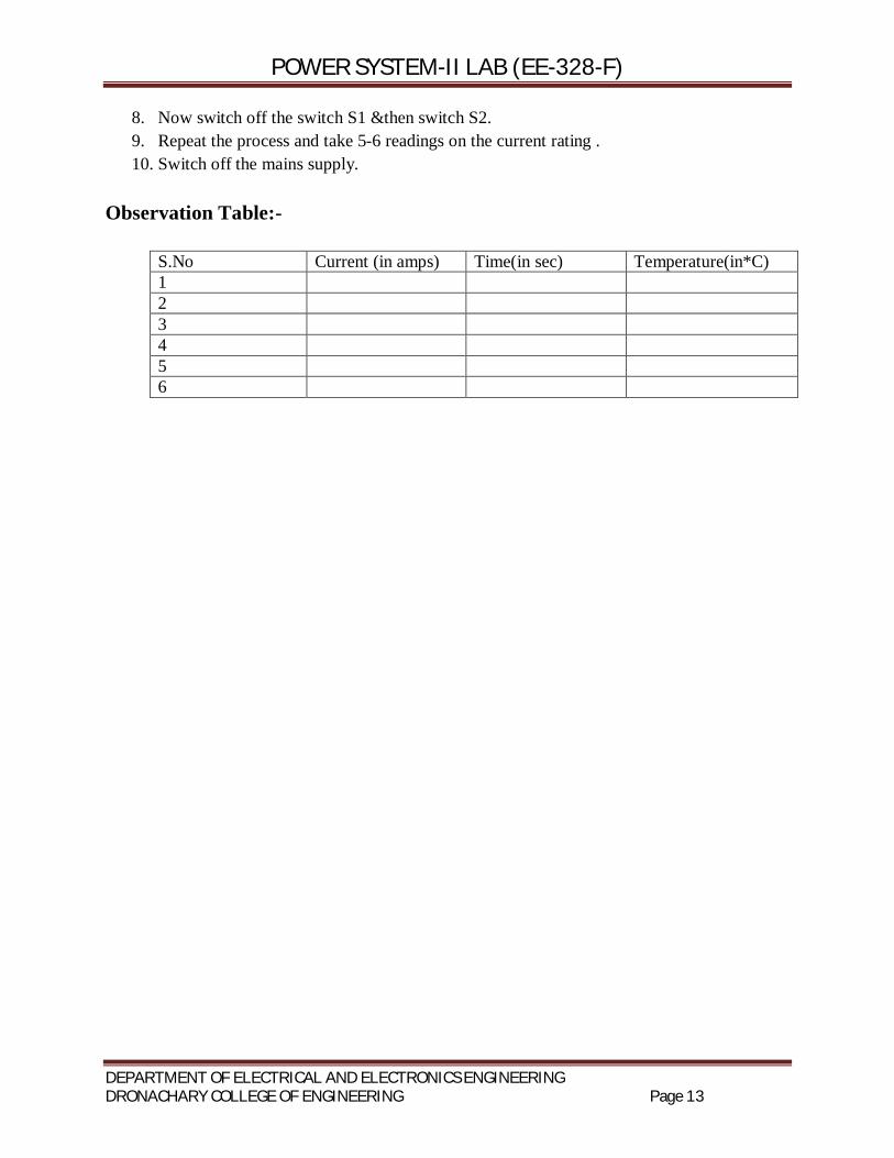
8. Now switch off the switch S1 &then switch S2. 9. Repeat the process and take 5-6 readings on the current rating . 10. Switch off the mains supply.
Observation Table:-
S.No Current (in amps) Time(in sec) Temperature(in*C) 1 2 3 4 5 6

POWER SYSTEM-II LAB (EE-328-F)
DEPARTMENT OF ELECTRICAL AND ELECTRONICS ENGINEERING DRONACHARY COLLEGE OF ENGINEERING Page 14
Experiment No-6
Aim:- To study the performance of over voltage relay.
Circuit Digram:
Theory: The operating torque is provided by the spring and restraining torque is proportional to the voltage. K1 – K2V2 > 0
Procedure:
1. Chose the required relay setting (% of 110V) and TSM
2. By the Autotransformer set the circuit to a particular PSM with DPDT at 1
3. Put the DPDT to 2 to reset the Relay (disc should return to it’s original position)
4. Switch over to 1 (DPDT), record the time of operation of the Relay, till the contactor trips.
5. Repeat 1-4 for at least two TSMs and two relay settings.
Precaution:
1. Slowly increase the Voltage to the required value.

POWER SYSTEM-II LAB (EE-328-F)
DEPARTMENT OF ELECTRICAL AND ELECTRONICS ENGINEERING DRONACHARY COLLEGE OF ENGINEERING Page 15
Experiment No-7
Aim: Determine the ABCD,H,Z and Image parameters of Short Transmission Line.
Apparatus Required:
Connecting Leads
Theory
The transmission lines which have length less than 80 km are generally referred as short transmission lines. For short length, the shunt capacitance of this type of line is neglected and other parameters like electrical resistance and inductor of these short lines are lumped.
1. Open Circuit the Output Terminal Procedure:
1. The AC supply is off and variac knob is at zero position 2. Make the connection according to the diagram. 3. Measure the sending end receiving end current and voltage respectively with the help of
switch S1,S2,S3 .
POWER SYSTEM-II LAB (EE-328-F)
DEPARTMENT OF ELECTRICAL AND ELECTRONICS ENGINEERING DRONACHARY COLLEGE OF ENGINEERING Page 16
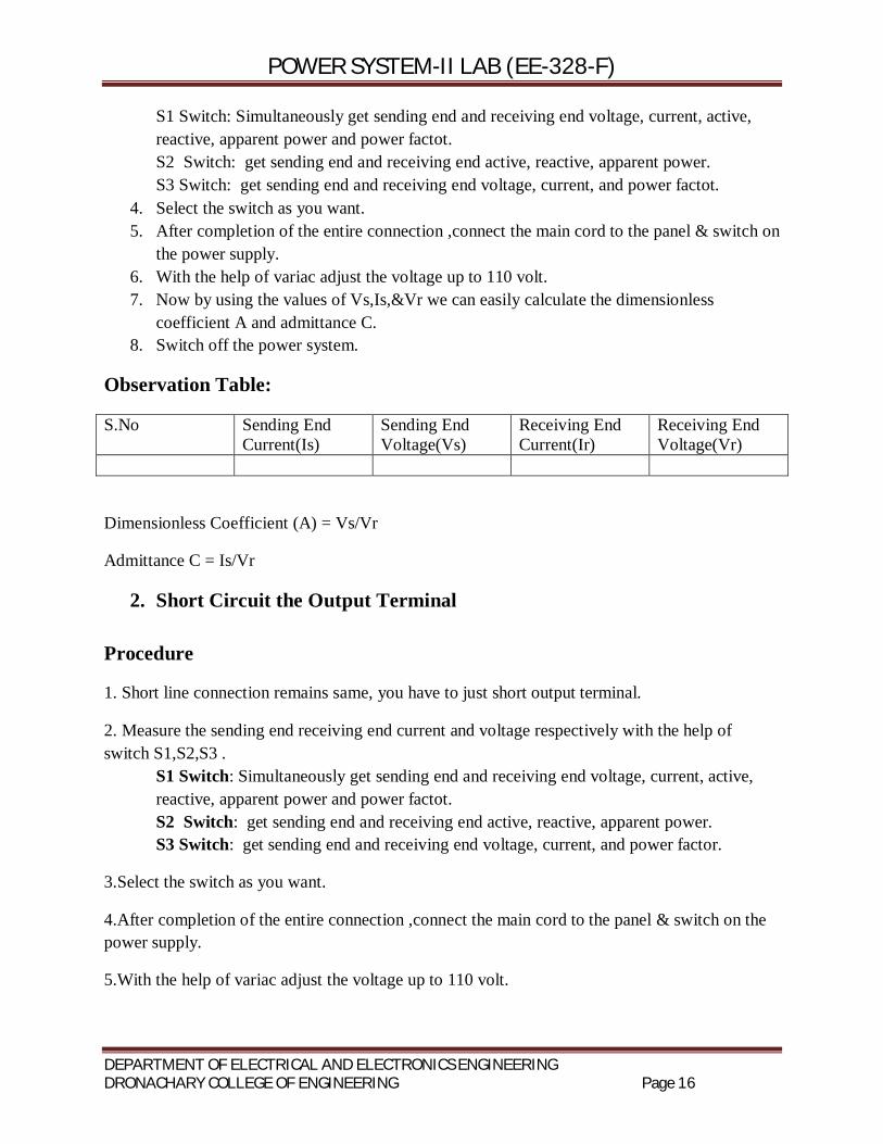
S1 Switch: Simultaneously get sending end and receiving end voltage, current, active, reactive, apparent power and power factot. S2 Switch: get sending end and receiving end active, reactive, apparent power. S3 Switch: get sending end and receiving end voltage, current, and power factot.
4. Select the switch as you want. 5. After completion of the entire connection ,connect the main cord to the panel & switch on
the power supply. 6. With the help of variac adjust the voltage up to 110 volt. 7. Now by using the values of Vs,Is,&Vr we can easily calculate the dimensionless
coefficient A and admittance C. 8. Switch off the power system.
Observation Table:
S.No Sending End Current(Is)
Sending End Voltage(Vs)
Receiving End Current(Ir)
Receiving End Voltage(Vr)
Dimensionless Coefficient (A) = Vs/Vr
Admittance C = Is/Vr
2. Short Circuit the Output Terminal Procedure
1. Short line connection remains same, you have to just short output terminal.
2. Measure the sending end receiving end current and voltage respectively with the help of switch S1,S2,S3 .
S1 Switch: Simultaneously get sending end and receiving end voltage, current, active, reactive, apparent power and power factot. S2 Switch: get sending end and receiving end active, reactive, apparent power. S3 Switch: get sending end and receiving end voltage, current, and power factor.
3.Select the switch as you want.
4.After completion of the entire connection ,connect the main cord to the panel & switch on the power supply.
5.With the help of variac adjust the voltage up to 110 volt.
POWER SYSTEM-II LAB (EE-328-F)
DEPARTMENT OF ELECTRICAL AND ELECTRONICS ENGINEERING DRONACHARY COLLEGE OF ENGINEERING Page 17
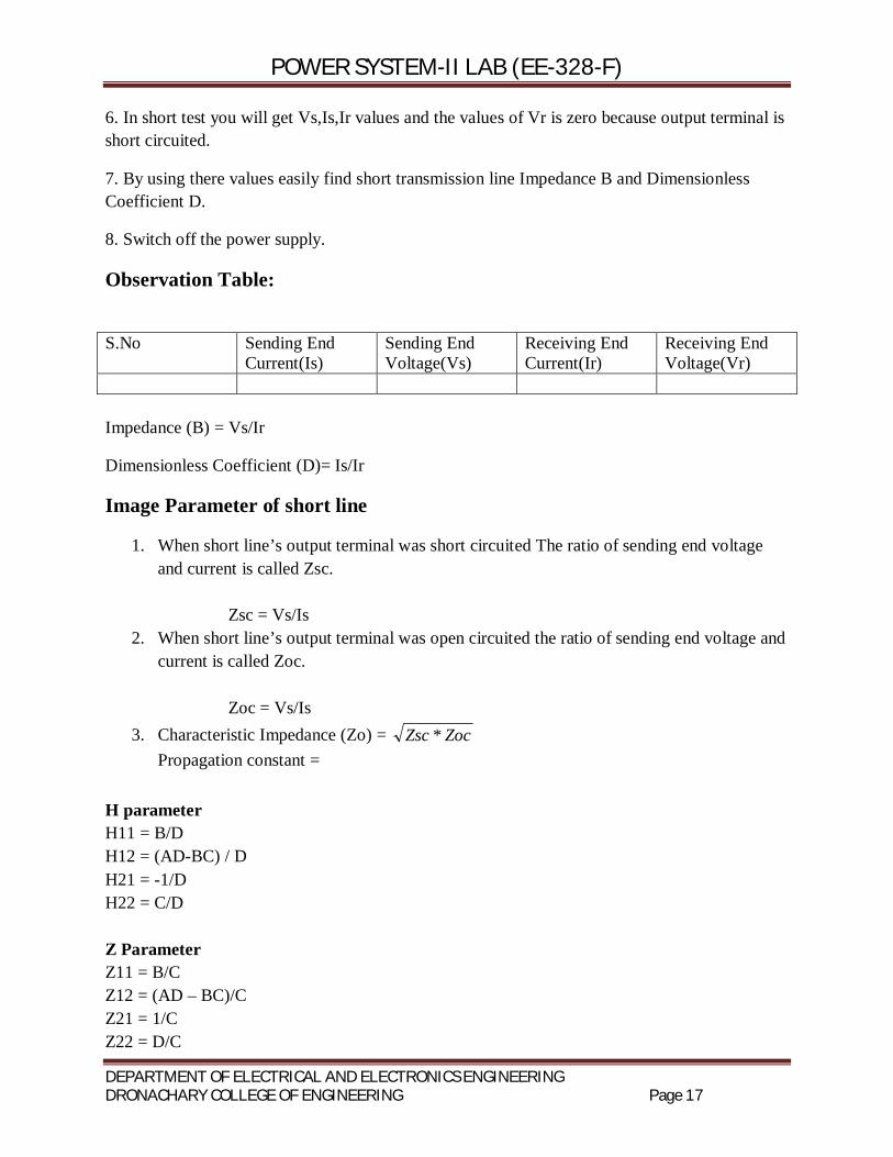
6. In short test you will get Vs,Is,Ir values and the values of Vr is zero because output terminal is short circuited.
7. By using there values easily find short transmission line Impedance B and Dimensionless Coefficient D.
8. Switch off the power supply.
Observation Table:
S.No Sending End Current(Is)
Sending End Voltage(Vs)
Receiving End Current(Ir)
Receiving End Voltage(Vr)
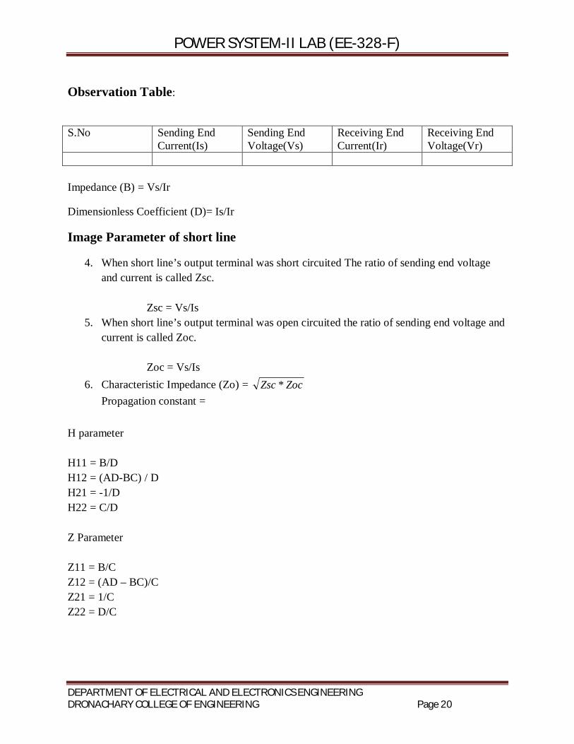
Impedance (B) = Vs/Ir
Dimensionless Coefficient (D)= Is/Ir
Image Parameter of short line
1. When short line’s output terminal was short circuited The ratio of sending end voltage and current is called Zsc. Zsc = Vs/Is
2. When short line’s output terminal was open circuited the ratio of sending end voltage and current is called Zoc. Zoc = Vs/Is
3. Characteristic Impedance (Zo) = ZocZsc * Propagation constant =
H parameter H11 = B/D H12 = (AD-BC) / D H21 = -1/D H22 = C/D Z Parameter Z11 = B/C Z12 = (AD – BC)/C Z21 = 1/C Z22 = D/C

POWER SYSTEM-II LAB (EE-328-F)
DEPARTMENT OF ELECTRICAL AND ELECTRONICS ENGINEERING DRONACHARY COLLEGE OF ENGINEERING Page 18
Experiment No-8
Aim: Determine the ABCD, H, Z and Image parameters of Medium Transmission Line.
Apparatus Required:
Connecting Leads
Theory
The transmission line having its effective length more than 80 km but less than 250 km, is generally referred to as a medium transmission line. Due to the line length being considerably high, admittance Y of the network does play a role in calculating the effective circuit parameters, unlike in the case of short transmission lines. For this reason the modelling of a medium length transmission line is done using lumped shunt admittance along with the lumped impedance in series to the circuit.
Procedure:
1. The AC supply is off and variac knob is at zero position 2. Make the connection according to the diagram. 3. Measure the sending end receiving end current and voltage respectively with the help of
switch S1,S2,S3 . S1 Switch: Simultaneously get sending end and receiving end voltage, current, active, reactive, apparent power and power factot. S2 Switch: get sending end and receiving end active, reactive, apparent power. S3 Switch: get sending end and receiving end voltage, current, and power factot.
4. Select the switch as you want. 5. After completion of the entire connection ,connect the main cord to the panel & switch on
the power supply.

POWER SYSTEM-II LAB (EE-328-F)
DEPARTMENT OF ELECTRICAL AND ELECTRONICS ENGINEERING DRONACHARY COLLEGE OF ENGINEERING Page 19
6. With the help of variac adjust the voltage up to 220 volt. 7. Now by using the values of Vs,Is,&Vr we can easily calculate the dimensionless
coefficient A and admittance C. 8. Switch off the power system.
Observation Table:
S.No Sending End Current(Is)
Sending End Voltage(Vs)
Receiving End Current(Ir)
Receiving End Voltage(Vr)
Dimensionless Coefficient (A) = Vs/Vr
Admittance C = Is/Vr
2.Short Circuit the Output Terminal
Procedure
1. Short line connection remains same, you have to just short output terminal.
2. Measure the sending end receiving end current and voltage respectively with the help of switch S1,S2,S3 . S1 Switch: Simultaneously get sending end and receiving end voltage, current, active, reactive, apparent power and power factot. S2 Switch: get sending end and receiving end active, reactive, apparent power. S3 Switch: get sending end and receiving end voltage, current, and power factot.
3.Select the switch as you want.
4.After completion of the entire connection ,connect the main cord to the panel & switch on the power supply.
5.With the help of variac adjust the voltage up to 220 volt.
6. In short test you will get Vs,Is,Ir values and the values of Vr is zero because output terminal is short circuited.
7. By using there values easily find short transmission line Impedance B and Dimensionless Coefficient D.
8. Switch off the power supply.
POWER SYSTEM-II LAB (EE-328-F)
DEPARTMENT OF ELECTRICAL AND ELECTRONICS ENGINEERING DRONACHARY COLLEGE OF ENGINEERING Page 20
Observation Table:
S.No Sending End Current(Is)
Sending End Voltage(Vs)
Receiving End Current(Ir)
Receiving End Voltage(Vr)
Impedance (B) = Vs/Ir
Dimensionless Coefficient (D)= Is/Ir
Image Parameter of short line
4. When short line’s output terminal was short circuited The ratio of sending end voltage and current is called Zsc. Zsc = Vs/Is
5. When short line’s output terminal was open circuited the ratio of sending end voltage and current is called Zoc. Zoc = Vs/Is
6. Characteristic Impedance (Zo) = ZocZsc * Propagation constant =
H parameter H11 = B/D H12 = (AD-BC) / D H21 = -1/D H22 = C/D Z Parameter Z11 = B/C Z12 = (AD – BC)/C Z21 = 1/C Z22 = D/C
POWER SYSTEM-II LAB (EE-328-F)
DEPARTMENT OF ELECTRICAL AND ELECTRONICS ENGINEERING DRONACHARY COLLEGE OF ENGINEERING Page 21
Experiment No- 9
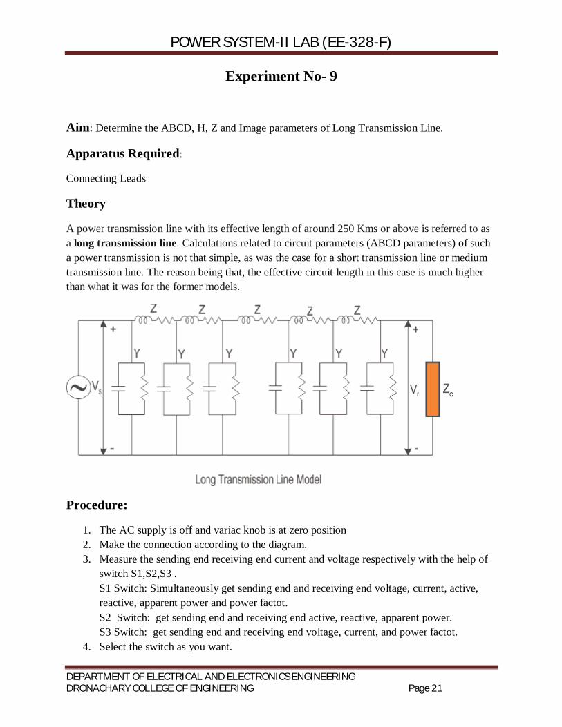
Aim: Determine the ABCD, H, Z and Image parameters of Long Transmission Line.
Apparatus Required:
Connecting Leads
Theory
A power transmission line with its effective length of around 250 Kms or above is referred to as a long transmission line. Calculations related to circuit parameters (ABCD parameters) of such a power transmission is not that simple, as was the case for a short transmission line or medium transmission line. The reason being that, the effective circuit length in this case is much higher than what it was for the former models.
Procedure:
1. The AC supply is off and variac knob is at zero position 2. Make the connection according to the diagram. 3. Measure the sending end receiving end current and voltage respectively with the help of
switch S1,S2,S3 . S1 Switch: Simultaneously get sending end and receiving end voltage, current, active, reactive, apparent power and power factot. S2 Switch: get sending end and receiving end active, reactive, apparent power. S3 Switch: get sending end and receiving end voltage, current, and power factot.
4. Select the switch as you want.
POWER SYSTEM-II LAB (EE-328-F)
DEPARTMENT OF ELECTRICAL AND ELECTRONICS ENGINEERING DRONACHARY COLLEGE OF ENGINEERING Page 22
5. After completion of the entire connection ,connect the main cord to the panel & switch on the power supply.
6. With the help of variac adjust the voltage up to 220 volt. 7. Now by using the values of Vs,Is,&Vr we can easily calculate the dimensionless
coefficient A and admittance C. 8. Switch off the power system.
Observation Table:
S.No Sending End Current(Is)
Sending End Voltage(Vs)
Receiving End Current(Ir)
Receiving End Voltage(Vr)
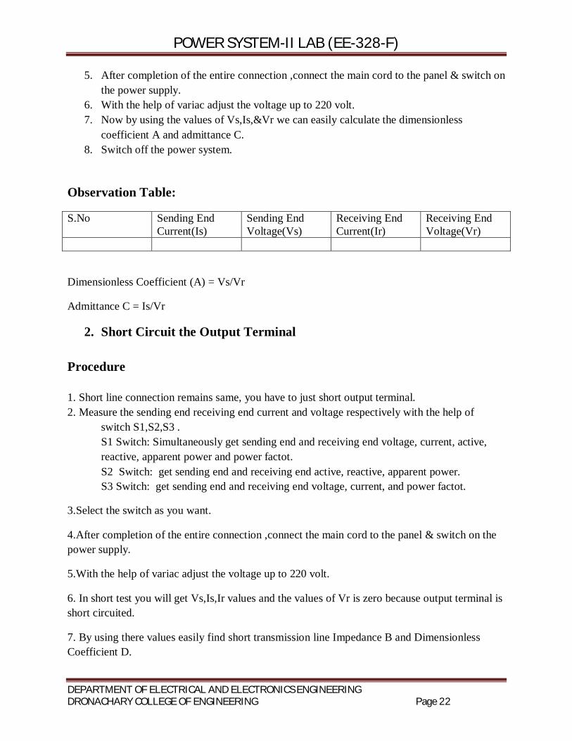
Dimensionless Coefficient (A) = Vs/Vr
Admittance C = Is/Vr
2. Short Circuit the Output Terminal Procedure 1. Short line connection remains same, you have to just short output terminal. 2. Measure the sending end receiving end current and voltage respectively with the help of
switch S1,S2,S3 . S1 Switch: Simultaneously get sending end and receiving end voltage, current, active, reactive, apparent power and power factot. S2 Switch: get sending end and receiving end active, reactive, apparent power. S3 Switch: get sending end and receiving end voltage, current, and power factot.
3.Select the switch as you want.
4.After completion of the entire connection ,connect the main cord to the panel & switch on the power supply.
5.With the help of variac adjust the voltage up to 220 volt.
6. In short test you will get Vs,Is,Ir values and the values of Vr is zero because output terminal is short circuited.
7. By using there values easily find short transmission line Impedance B and Dimensionless Coefficient D.
POWER SYSTEM-II LAB (EE-328-F)
DEPARTMENT OF ELECTRICAL AND ELECTRONICS ENGINEERING DRONACHARY COLLEGE OF ENGINEERING Page 23
8. Switch off the power supply.
Observation Table:
S.No Sending End Current(Is)
Sending End Voltage(Vs)
Receiving End Current(Ir)
Receiving End Voltage(Vr)
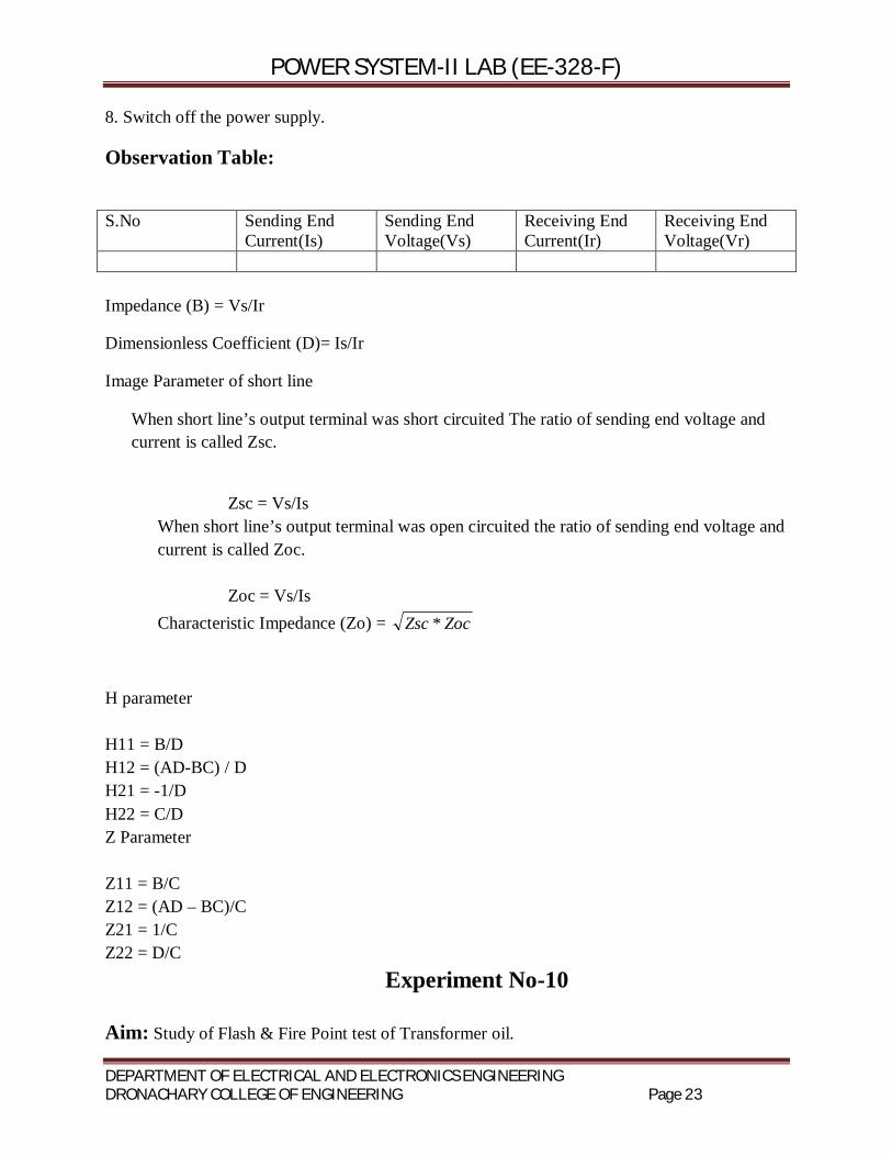
Impedance (B) = Vs/Ir
Dimensionless Coefficient (D)= Is/Ir
Image Parameter of short line
When short line’s output terminal was short circuited The ratio of sending end voltage and current is called Zsc.
Zsc = Vs/Is When short line’s output terminal was open circuited the ratio of sending end voltage and current is called Zoc. Zoc = Vs/Is Characteristic Impedance (Zo) = ZocZsc *
H parameter H11 = B/D H12 = (AD-BC) / D H21 = -1/D H22 = C/D Z Parameter Z11 = B/C Z12 = (AD – BC)/C Z21 = 1/C Z22 = D/C
Experiment No-10 Aim: Study of Flash & Fire Point test of Transformer oil.

POWER SYSTEM-II LAB (EE-328-F)
DEPARTMENT OF ELECTRICAL AND ELECTRONICS ENGINEERING DRONACHARY COLLEGE OF ENGINEERING Page 24
Apparatus Required:
1. Transformer Oil 2. Electric Lighter
Theory: Transformer oil or insulating oil is a highly refined mineral oil that is stable at high temperatures and has excellent electrical insulating properties. It is used in oil-filled transformers, some types of high voltage capacitors, fluorescent lamp ballasts, and some types of high voltage switches and circuit breakers. Its functions are to insulate, suppress corona and arcing, and to serve as a coolant. Procedure:
1. Ensure that mains switch at the control set-up is at off position 2. Clean oil cup carefully to avoid any contamination and fill half a cup from transformer oil 3. Keep the oil cup into its respective position 4. Adjust the thermostat rod in such a way that it must be half filled into oil cup and tighten it by
providing screw on its stand. 5. Cover up oil cup. 6. Switch on mains as well as the MCB 7. Observe the temperature start increasing from its normal temperature. 8. Now observe the oil until it evaporates and vapour comes out from the oil cup. 9. Now use electric lighter to ignite the oil by uncover half of the oil cup. 10. Times when oil catch fire for a large time indicates fire point of the oil. 11. Cover up the oil cup to extinguish fire into oil cup. 12. Push heating on/off switch to stop heating indicated by red LED blow out. 13. Switch off mains as well as the MCB.
Results:
Flash Point of the Transformer oil:-
Fire Point of Transformer oil:-